G.S.I AC Controller. Installation & User Guide
|
|
|
- Cory Bradford
- 6 years ago
- Views:
Transcription


1 G.S.I AC Controller Installation & User Guide
2 2012 Galcon. All rights reserved. Information in this documentation is subject to change without notice and does not represent a commitment on part of Galcon. The software described in this document is subject to the license agreement that is included with the product, which specifies the permitted and prohibited uses of the product. Any unauthorized duplication or use of this documentation, in whole or in part, in print, or in any other storage or retrieval system is prohibited. No part of this publication may be reproduced, transmitted, transcribed, stored in a retrieval system, or translated into any language in any form by any means for any purpose other than the purchaser s personal use without the permission of Galcon. Contact Us Galcon Kfar Blum 12150, Israel Tel: Fax: info@galconc.com Visit us at:
3 Table of Contents 1 Introduction... 4 G.S.I Controller Models Setting Up the G.S.I Controller... 5 Installing the Controller...5 Installing on a Wall or in a Control Cupboard...5 Establishing the Electrical Connections...7 Connecting the Solenoids to the Controller...7 Connecting AC Power...8 Connecting Backup Batteries...8 Connecting a Rain Sensor and Flow Meter...9 Inserting a SIM Card On-Site Controller Operation Main Screen Features...11 Establishing Communication with the Server...12 Manually Setting the Controller Clock...13 Testing Station Operation...13 Creating an Irrigation Program...14 Setting Irrigation Program Durations...14 Setting the Irrigation Cycle Time...15 Setting the Irrigation Start Day and Time...16 Cancelling an Irrigation Program Start...17 Initiating Immediate Irrigation for a Station...17 Resetting the Controller...17 Pausing and Resuming Irrigation from the Controller...18 System Alerts...19 Fault Messages...19 Canceling Fault Alerts...19 General System Messages...19 Locking and Unlocking the Screen Technical Specifications
4 List of Figures Figure 1: Open Controller Cover...6 Figure 2: Control Panel Swung Outward...6 Figure 3: Opening the Internal Casing...6 Figure 4: Mounting Screw Holes on Back of Unit...6 Figure 5: Mounting Screw Holes Dimensions...6 Figure 6: Inserting the Mounting Screws with Cover Caps...6 Figure 7: Controller Terminal Blocks...7 Figure 8: Battery Compartment Removed...8 Figure 9: SIM Card Case...10 Figure 10: SIM Card Insertion Orientation...10 Figure 11: Correctly Inserted SIM Card...10 Figure 12: Main Screen...11 Figure 13: Test Screen...13 Figure 14: Test Sequence Screen...13 Figure 15: Duration Screen Example...14 Figure 16: Cycle Screen...15 Figure 17: Twelve Hour Cycle Setting Example...15 Figure 18: Six Day Cycle Setting Example...16 Figure 19: Start Day Screen Example
5 1 Introduction The Galcon G.S.I Controller is a controller which functions as the intermediary between central Galcon servers and the irrigation valves in the field. Creating irrigation programs for the G.S.I Controller is primarily done from the G.S.I Internet application. However, you can also create a simple irrigation program directly on the controller even before setting up the Internet application. You can also perform manual irrigation direct from the controller. This manual describes how to install the G.S.I Controller, test to verify successful installation, perform basic, initial irrigation programming, and perform manual valve irrigation. For information about using the G.S.I Internet application, refer to the G.S.I Internet application User Guide. G.S.I Controller Models There are two models of the G.S.I Controller, based on the type of power supply used: DC unit, which supports either Alkaline or Lithium batteries. AC unit. This document describes the AC unit type. 4 4
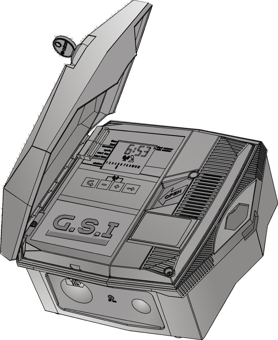
6 2 Setting Up the G.S.I Controller Setting up the G.S.I Controller system includes the following tasks: Installing the Controller (see page 5) Establishing the Electrical Connections (see page 7) Installing the Controller The controller is designed to withstand outdoor installation conditions (at a rating of IP65). However it is preferable to provide additional protection from the climate by installing it in a sheltered position. Appropriate installation of the controller will ensure dependable operation throughout the years. Installing on a Wall or in a Control Cupboard To install the controller on a wall or in a control cupboard: 1. Unlock and open the controller cover (Figure 1). 2. Swing out the control panel (Figure 2). 3. For the internal casing on the right side, unscrew the two screws and open the casing (Figure 3). Mount the controller to the wall or to the control cupboard through the marked holes (Figure 4 and Figure 5) with the aid of the three screws. Close the screws by hand only. For water sealing, cover the screws with the supplied cover caps (Figure 6). 4. Close the internal casing and fasten its screws. 5. Swing the control panel back into place. 6. Close and lock the controller cover. 5 5


7 Figure 1: Open Controller Cover Figure 2: Control Panel Swung Outward Figure 3: Opening the Internal Casing Figure 4: Mounting Screw Holes on Back of Unit Figure 5: Mounting Screw Holes Dimensions Figure 6: Inserting the Mounting Screws with Cover Caps 6 6

8 Establishing the Electrical Connections The AC G.S.I Controller has the following output connectors: 12 or 24 irrigation valves Master valve The G.S.I Controller has the following inputs: Rain sensor Water meter / Flow sensor Connecting the Solenoids to the Controller To connect the solenoids to the controller: 1. Insert the solenoid wires through the cable gland at the bottom of the controller and connect them. 2. Connect one wire coming from the solenoid to one of the outputs labeled with a number (1-24). 3. Connect the second wire to one of the common outputs, labeled C. Figure 7: Controller Terminal Blocks Note: It is highly recommended that you label the input wires, by function, for future reference. 7 7
. 2. Swing out the control panel (Figure 2). 3. For the internal casing on the right side, unscrew the two screws and open the casing (Figure 3). 4.")
9 Connecting AC Power Warning! Connecting to primary power source must be performed by a qualified electrical technician, following all local codes. To connect AC power: 1. Unlock and open the controller cover (Figure 1). 2. Swing out the control panel (Figure 2). 3. For the internal casing on the right side, unscrew the two screws and open the casing (Figure 3). 4. Route the AC power cable through the 1/2" pre drilled hall at the bottom of the controller. Always use 1/2" approved conduit male adaptor when installing the AC wiring. 5. Connect the wires to the feed through terminal block. The terminal block can be pulled out to be more easily accessed. Connect hot to the brown wire, natural to the blue wire, and ground to the yellow wire. 6. Proceed to backup battery installation below. Connecting Backup Batteries You must install backup batteries. In the event of a power failure, the batteries keep the controller functional, including enabling the modem to send power failure alerts. To connect a backup battery: 1. Turn the battery compartment latch by 90 degrees and pull out the battery compartment. Figure 8: Battery Compartment Removed 2. Insert four AA 1.5 Volt batteries (not supplied), as a backup power source, into the battery compartment. 8 8
10 3. Return the battery compartment and lock it in place by turning the latch back until it clicks. 4. Close the internal casing and fasten its screws. 5. Swing the control panel back into place. 6. Close and lock the controller cover. Connecting a Rain Sensor and Flow Meter The GSI unit supports the following input devices: Rain sensor Water meter To connect the input wires: Rain sensor Connect one of the rain sensor wires to the connector labeled Rs, and connect the second sensor wire to one of the connectors labeled C. The polarity of the wires is not important. Flow meter Connect one of the flow meter wires to the connector labeled Ws, and connect the second wire to one of the connectors labeled C. The polarity of the wires is not important. Note: You must define the rain sensor and flow meter in the G.S.I Internet application before you can use them. Inserting a SIM Card The SIM card case is located on the upper left side of the controller board. Note: Your SIM card definitions should already have been set by the manufacturer. If you are inserting an independent SIM card and you need to set its definitions yourself, refer to the document SIM Card Definitions provided by Galcon. To insert a SIM card: 1. Unlock and open the controller cover (Figure 1). 2. Swing out the control panel (Figure 2). 3. Locate the SIM card case. 9 9


11 Figure 9: SIM Card Case 4. Slide the SIM card case cover to the side to open it, as indicated by the arrow labeled OPEN (see Figure 11). 5. Open the cover and slide the SIM card into the grooves located on the inner part of the case cover. Make sure that you have oriented the SIM card correctly. 6. Close the case cover. Figure 10: SIM Card Insertion Orientation 7. Hold the SIM card case cover down while you slide the cover to the side, as indicated by the arrow labeled LOCK (Figure 11). 8. Swing the control panel back into place. 9. Close and lock the controller cover. Figure 11: Correctly Inserted SIM Card 10 10
12 3 On-Site Controller Operation The Galcon G.S.I Controller is designed to run irrigation programs created using the online G.S.I Internet application. In addition, however, the G.S.I Controller includes a control panel which enables basic, initial program creation. The following sections outline how to set up the G.S.I Controller, create a basic irrigation program, and perform other irrigation and troubleshooting tasks. Note: Programs defined from the G.S.I Controller control panel continue to operate until you explicitly deactivate them from the G.S.I Internet application, even if you upload a different program from the application. Main Screen Features You can view information and monitor irrigation programs directly from the G.S.I Controller Main screen. Figure 12: Main Screen Press to cycle through the following information displays on the Main screen: Current time (hh:mm format) Flow value currently detected by the flow sensor (in m 3 /hr). Notes: Until the flow sensor is defined using the G.S.I Internet application, this screen does not display actual data. When there is no water flow, the flow value should be zero. If it is not, contact Galcon Support. Current voltage of the controller s backup battery Last four digits of the controller unit s 16-digit serial number Current firmware version number 11 11
13 The Main screen is the launching point for all other G.S.I. controller operations. It displays the following information depending on the circumstances: By default Displays the current time (hh:mm format). During irrigation Displays a icon below the irrigation station in the list which is currently performing irrigation, as well as the amount of time remaining until that irrigation process finishes. If more than one station is currently performing irrigation, the icon is displayed for each of them. In addition, a icon is displayed below one of those stations and the time displayed applies for that station. Optionally press to cycle through the following information: Current program number Current water flow Current time Press again to return to the main irrigation screen which displays the current irrigation program countdown. In addition, on the left side of the screen, an icon indicates which screen you are currently viewing according to the list of screens printed on the unit. Establishing Communication with the Server When setting up the G.S.I Controller for the first time, establishing communication with the server automatically sets the controller clock. Generally, communication is established automatically as soon as the G.S.I Controller is activated. However, in situations where this does not occur, you can manually establish communication with the server. To manually establish communication: Press and simultaneously. The icon flashes on the screen while the unit synchronizes with the server. After the unit is synchronized, the and icons flash alternatively as long as the controller is in communication mode. When the upload/ download session is complete, the controller automatically ends communication and the controller display returns to the Main screen. To end communication manually: Press and simultaneously. Communication immediately ends. The controller display returns to the Main screen
14 Manually Setting the Controller Clock In order for the controller to correctly operate the irrigation system at the desired times, the controller clock must first be set correctly. The controller clock is automatically updated every time the controller communicates with the server. You can also manually set the time. To manually set the controller time: 1. Press and hold until the minutes value in the displayed time start flashing. This indicates that the clock is in time-setting mode. Set the current time using the and buttons. 2. Press to exit time-setting mode, and press repeatedly until the Main screen is displayed. Verify that the time you set is correctly displayed. Testing Station Operation The station operation test is intended to verify that all of the solenoids have been correctly installed. As you perform the test for each station, verify that water is flowing by checking the controller, the flow sensor, or even by visually inspecting the sprinklers to check that water is flowing from them. To test station operation: 1. Press until the Test screen is displayed (Figure 13). 2. Press and hold until the Test Sequence screen is displayed (Figure 14). The controller automatically begins operating the master station and each of the stations in sequence, for 60 seconds each. The currently operating station is marked with the icon, and the screen displays the number of seconds remaining for that station s operation test. Figure 13: Test Screen Figure 14: Test Sequence Screen You can optionally extend or shorten a station operation test as follows: To extend or to shorten the operation test time of the current station, press or respectively. To close an operating station before its test time has elapsed and move to the next station, press. The icon moves according to your selection. To end the test sequence completely, press and simultaneously. The controller closes all the stations
15 Creating an Irrigation Program Notes: When locally creating the irrigation program: Stations always run in the order of their numbers. You can set a different duration for each station. The cycle time, start day, and start time apply for the first station in the sequence. As one station s irrigation duration ends, the next station automatically begins. Locally created irrigation programs continue operating even after you upload a detailed program from the G.S.I Internet application both programs will operate side by side. If you want to end the locally created program, you must cancel it in the G.S.I Internet application explicitly, or from the controller Setting Irrigation Program Durations Irrigation program duration, also known as the run time, can be defined for each station. To set the irrigation program duration: 1. Press until the Duration screen is displayed (Figure 15). 2. Press to move the cursor and select the station for which you want to define the irrigation duration. 3. Press and to set the irrigation duration for the selected station. In Figure 15, the duration set is for 2 hours and 40 minutes for station 3. A duration of 0:00 sets the station to never open its valves (and therefore the sequence skips to the next station immediately). Figure 15: Duration Screen Example 14 14
16 Setting the Irrigation Cycle Time You can set an irrigation program to occur one time only, or to occur repeatedly according to a cycle. When setting a recurring cycle, the cycle value you set defines the length of time (in hours or days) which passes between irrigations program start times. To set a one-time irrigation program: 1. Press until the Cycle screen appears (Figure 16). The message OncE is displayed by default, indicating that the cycle pattern is set to one time only. If a cycle value other than OncE was previously set for the system, press repeatedly until the message OncE appears. 2. Press to progress to the next screen, which automatically saves the change. Figure 16: Cycle Screen To set cyclical irrigation programs: 1. Press until the Cycle screen appears (Figure 17). 2. Press once. The display changes from OncE to h 00, indicating zero hours. 3. Press and to increase and decrease the number of hours. Figure 17: Twelve Hour Cycle Setting Example If you increase past 24 hours, the display changes to d 01, indicating one day. You can continue to press to increase the number of days up to 30 days
17 Figure 18: Six Day Cycle Setting Example 4. After setting the desired cycle length, press to progress to the next screen, which automatically saves the change. Setting the Irrigation Start Day and Time The start day is the number of days between the day you define an irrigation program (today) and the day the program actually begins operating. The start time is the time of day the program begins. To set the start day and time: 1. From the Main screen, press until the Start Day screen appears (Figure 19). Figure 19: Start Day Screen Example The default display is d 00 which indicates zero days. If you set this value for the start day, the irrigation program will start on the current day at the defined start time. If that time has already passed for the current day, the program starts at that time the next day. 2. Press and to increase and decrease the number of days. In Figure 19, the value is set to 10 days. The maximum supported value is 30 days. 3. Press to save the defined start day and continue to define the start time in the Start Time screen. The default setting is Off, which means that the irrigation program never starts. 4. Press and to set the start time. The possible range of values is 0:00 to 23:59. Alternatively, you can cycle through the time settings until reaching the open option. Setting the start time to open causes the irrigation cycle to start immediately after you save the start time setting (overriding the defined start day). 5. Press to progress to the next screen, which automatically saves the change
18 Cancelling an Irrigation Program Start To cancel an irrigation program start: 1. From the Main screen, press until the Start Time screen appears. 2. Press until the start time is set to Off. This defines that the irrigation program will never start. 3. Press to progress to the next screen, which automatically saves the change. Initiating Immediate Irrigation for a Station In addition to defining an irrigation program, you can initiate any station to immediately begin irrigating. The irrigation is performed for the amount of time defined for that station s duration in the irrigation program you created using the controller s direct interface. This is true even if you have already uploaded a different program from the G.S.I Internet application. If no duration has been defined, the duration used is one minute. To initiate immediate irrigation for a station: 1. From the Main screen, press until the Start Time screen appears. 2. Press to select a station. 3. Press. The station immediately starts irrigating for the length of its defined duration. 4. Optionally, press or to increase or decrease the duration of the current irrigation. Resetting the Controller If a technical problem occurs, you may want to reset your G.S.I Controller. To reset the controller: Press the Reset button, located in the top-left corner of the G.S.I Controller s circuit board. The reset process clears the controller s RAM, and performs the flowing sequence of operations: a. All the screen icons appear simultaneously on the screen and gradually disappear after a few minutes. b. The screen displays the controller s serial number followed by the current firmware version on the controller. c. The screen displays the numbers of the valves connected to the controller. The controller starts closing the valves one by one; as each valve is closed, its number disappears from the screen and the CL OS message is displayed. Optionally press to abort this process and skip to the next operation
19 d. The controller establishes communication with the server; the icon flashes on the screen as long as the controller is in communication mode. e. The controller ends communication and resumes normal operation. Note: Resetting the controller does not delete or cancel the locally created irrigation program. Pausing and Resuming Irrigation from the Controller The controller enables you to pause irrigation. While a pause is in effect, all irrigation programs currently in progress are paused, and any new irrigation programs which were scheduled to start are not started. While irrigation is paused in this way, you can still perform station operation tests and establish communication with the server. When the pause is ended and irrigation is resumed, all irrigation programs continue according to the following rules: While paused, programs are delayed until midnight. As such, if the pause is ended before midnight the programs resume where they left off, and scheduled programs for that period will run. If the system pause condition ended after midnight, all delayed programs are canceled and will initiate irrigation according to their next scheduled timing. To pause an irrigation program: Press continuously until the message PA US is displayed on the screen. This indicates that the irrigation is now paused. The PA US message flashes on the screen until you resume irrigation. To resume irrigation: Press continuously until the Main screen is displayed. Note: the controller will react according to the paused rules also in the following occasions: AC power off Rain sensor activation 18 18
20 System Alerts The G.S.I Controller features various kinds of system alerts, including fault messages and other problem indicators. Fault Messages If a fault occurs in the system, the controller screen displays the message FLt or FL and a fault number. Table 1: Fault Numbers and Definitions Fault Indication Message FLt 0 FLt 1 FLt 2 FLt 3 FL 11 FL 12 FL 13 Description Low flow fault High flow fault No water flow fault Uncontrolled water flow fault Station definition fault Irrigation program fault Controller memory fault Canceling Fault Alerts To cancel an alert and remove the fault message from the screen: With the fault message displayed, press and simultaneously. General System Messages Flashing low battery icon When the backup battery is low, a flashing battery icon appears on the display. This indicates that the backup battery should be replaced. AC Off If for any reason the controller stops receiving AC power from the main line, a blinking AC icon is displayed. While this is the case, the controller can still be programmed and manual communication will still be possible, as long as backup battery power is available. However, valves cannot be opened and programs cannot be performed according to the schedule. Valve short circuit In the event of a short circuit in a valve, or one of its connections, a icon flashes on the display over the relevant valve number, and the word Shrt is displayed for few seconds. The flashing icon remains on the screen until the valve is restored to successful operation. The next time the valve is scheduled to be opened, the controller tries opening the valve again
21 Locking and Unlocking the Screen The G.S.I Controller enables you to lock the screen, preventing people from editing the unit s programming until the screen is unlocked. To lock the screen: Press, and at the same time. The screen is locked and displays = = = =. To unlock the screen: Press, and at the same time. The screen is unlocked and the unit can be programmed
22 4 Technical Specifications Transformer input: 230V 50 Hz, or 110V 60 Hz for American models Transformer output: 24VAC 2.5 amp Station output: 0.5 amps per station Maximum output: 4+1 (Master) Electronic short circuit protection Non-Volatile memory for program data Backup Batteries: 4X1.5V A type Batteries. Cellular modem: Quad band GSM modem integrated (GPRS class 10) for operating in all GSM operators globally. Dimensions: 10.5x24.5x25.5 CM Operating ambient temperature: -10 C to 60 C, 14 F to 140 F
23 Warranty LIMITED WARRANTY CERTIFICATE 1. Galcon shall, for a limited period of 36 months from the retail purchase date of the original (first) purchaser ( the Warranty Period ), provide limited warranty for the Products, as provided for and subject to the provisions and limitations of this Limited Warranty Certificate Galcon s Warranty for the Product only extends to the original purchaser of the Product ( the Customer ) who, upon requesting warranty service, must present Galcon with a valid purchase receipt. Failure to produce the said documentation will result in the request for warranty being null and void GALCON warrants to the Customer that the Product shall materially conform to the description in Galcon s documentation and shall be free from defects in material and workmanship. Accordingly, Customer s sole and exclusive remedy under this warranty is the repair or to Galcon s sole discretion the replacement of the Product or any part\s according to the terms of this Warranty, and no other remedy shall be available. Therefore, if - within the Warranty Period - the Product is proven to be defective by reason of faulty workmanship or materials by Galcon, Galcon undertakes, with reasonable promptness, to have the defective Product (or any part/s thereof) repaired, or at Galcon s discretion, replaced; All subject to the terms and conditions of this Limited Warranty Certificate Galcon s warranty for the Product or otherwise shall not apply to any of the following: (i) any conduct (by act or omission) not by Galcon, including any misuse/abuse of any Product (or part/s thereof), and/or any failure to install and/or use any Product in full compliance with Galcon s instructions; (ii) other systems/components/devices/technologies and/or the integration/interface thereof with any Product; (iii) any part/component which has been included/installed in any Product not at Galcon s approval and/or other than by Galcon; (iv) any actual or attempted change/repair/interference of/with any Product (including any use/handling of, and/or interference/dealing with, any code of any software included/used in the Product) other than by Galcon; (v) any data/information/content which has been inserted/included in a Product; (vi) malfunction or damage resulting from accidents, which occur during transit and/or handling, and/or malfunction or damage due to fire, earthquake, flood, lightning and/or any other external disaster; (vii) unforeseen accidents, wear and tear, or any other external factors beyond Galcon s reasonable control, or to any Product installed, repaired, adjusted, rebuilt, modified, changed or converted by any person (including the Customer) other than Galcon; In addition and without derogating from the provisions of this Warranty, Galcon s warranty is conditioned upon the all of the following taking place: (i) Customer s operating and maintaining the Product in accordance with Galcon s instructions; (ii) Customer s not being in default of any payment obligation to the Galcon (or its authorized dealer, as relevant) Galcon does not give any warranty or guarantee whatsoever in respect of any Product (or any part/s thereof) which has not been manufactured and distributed by the Galcon and which has not been purchased from the Galcon or any of its authorized dealers, whether such products are branded with any trademarks similar to any trademark belonging to or used by Galcon After replacement or repair of the Product, the Warranty for the new or repaired Product shall be valid only for the non-expired period of the original Warranty Period. Any defective Products or part/s, which has been replaced, shall become Galcon s property Galcon reserves the right to charge the Customer if any warranty service is requested and carried out but no fault is found in the Product or if such defect/fault is not under Galcon s Warranty Notwithstanding anything to the contrary, Galcon shall not be responsible and/or liable, under any circumstances and in any way, for any loss, damage, costs, expenses, expenditures, responsibility and/or liability (including of Customer and/or any third party) including (without limitation) direct and/or indirect (including incidental and/or special and/or consequential), however arising, including in respect of damages to or loss of property and/or equipment, loss of profit, loss of use, loss of revenue or damages to business or reputation, whether or not based on breach of contract, tort (including negligence), product liability or otherwise - arising from the performance or nonperformance of any aspect of the Product or any part thereof; All of the above, whether or not Galcon and/or the Customer shall have been made aware of the possibility of such loss In any event, any liability which Galcon may have in connection with the Product and/or this Warranty, including (without limitation) in connection with and/or resulting from the Product (or any part thereof) and the use thereof, shall be limited to a total amount (for all damages, claims and causes of action in the aggregate) equal to the consideration actually received by Galcon from the Customer for the Product. The limitations shall apply whether the liability is based on contract, tort, strict liability or any other theory This Warranty and the remedies set forth herein are exclusive and in lieu of all other warranties, remedies and conditions, whether oral, written, statutory, express or implied. Galcon specifically disclaims any and all statutory or implied warranties, including, without limitation, warranties of merchantability and fitness for a particular purpose and warranties against hidden or latent defects The Customer shall be solely responsible for the selection, use, efficiency and suitability of the Product(s) The provisions of this Limited Warranty Certificate shall be interpreted and governed, solely and exclusively, pursuant to the laws of the State of Israel, and no other law shall apply. Any and all legal actions shall be litigated within the jurisdiction of the courts of Israel, and no other jurisdiction shall apply.
24 Residential Gardening Turf & Landscape agriculture waterworks Galcon Website
Single Station Waterproof Timer
 Single Station Waterproof Timer Installation and Programming Guide Features Up to four irrigation cycles per day Easy installation and programming Battery powered Waterproof and weather resistant 1234
Installation & Operation Manual. BEC PM1 Controller Time/Flow/Volume Controller. Water Control Solutions
 Installation & Operation Manual BEC PM1 Controller Time/Flow/Volume Controller Water Control Solutions Table of Contents Introduction 4 Chapter 1 Technical Data and I/O Connections 6 DC Solenoid 6 Power
MWT-FM. Operation Manual. FM Single Channel Transmitter. man_mwtfm.
 MWT-FM FM Single Channel Transmitter Operation Manual man_mwtfm www.myeclubtv.com CONTENTS FCC COMPLIANCE STATEMENT. 3 INDUSTRY CANADA COMPLIANCE 3 MWT-FM ORIENTATION. 4 SAFETY PRECAUTIONS 5 FINDING FM
Junior Max (JR Max ) Controller
 Controller") Get more done TM Junior Max (JR Max ) Controller stations Operating Instructions Thank you for purchasing this advanced, highly featured Irritrol Junior MAX controller. The Junior MAX is the latest addition
Get more done TM Junior Max (JR Max ) Controller stations Operating Instructions Thank you for purchasing this advanced, highly featured Irritrol Junior MAX controller. The Junior MAX is the latest addition
Battery Operated Controllers
 ALL SEASONAL ADJUSTMENT 1 Battery Operated Controllers Owner s Manual and Programming Instructions RUN PRG SENSOR BYPASS SYSTEM OFF CURRENT TIME/DAY ACTIVE MANUAL-ALL STATIONS START TIMES MANUAL-ONE STATION
blink USER GUIDE Bluetooth capable Reclocker Wyred 4 Sound. All rights reserved. v1.0
 blink Bluetooth capable Reclocker USER GUIDE Wyred 4 Sound. All rights reserved. v1.0 Table of Contents READ FIRST Important 1 Package contents 1 About the blink Bluetooth Streamer/Reclocker 1 Connectivity
CH1 CH2 CH3 CH4. Master /Fade CH5. 600s CH6. 60s SC1 SC2 SC4 SC3 SC5. SC6 Off/Pro. AL Fade 6 Pro. User guide
 1 1 CH1 CH2 1 1 CH4 CH 1 CH3 6s Master /Fade CH6 1 SC1 6s SC4 SC2 SC SC3 SC6 Off/Pro AL Fade 6 Pro User guide CONTENTS INTRODUCTION...2 Welcome 2 Safety 2 Supplied items 3 INSTALLATION...4 Mounting 4
Chapter 1 : FCC Radiation Norm...3. Chapter 2 : Package Contents...4. Chapter 3 : System Requirements...5. Chapter 4 : Hardware Description...
 Table of Contents Chapter 1 : FCC Radiation Norm...3 Chapter 2 : Package Contents...4 Chapter 3 : System Requirements...5 Chapter 4 : Hardware Description...6 Chapter 5 : Charging Your Video Watch...7
User Instructions. 16 SCB Sync Station.
 User Instructions 16 SCB Sync Station Contents Overview... 1 Specifications... 1 Compliance and approvals... 2 Safety instructions... 3 Set up... 4 How to charge multiple devices... 4 How to synchronize
CR-R880-BL: Indoor/Outdoor Proximity Reader with 10cm (4in) read range
 read range") CR-R880-BL: Indoor/Outdoor Proximity Reader with 10cm (4in) read range Installation Manual Table of Contents Basic Operation...2 CR-R880-BL Block Diagram...2 Technical Specifications...3 Features...4
CR-R880-BL: Indoor/Outdoor Proximity Reader with 10cm (4in) read range Installation Manual Table of Contents Basic Operation...2 CR-R880-BL Block Diagram...2 Technical Specifications...3 Features...4
Sport-TIMER 3000 TM Instruction Manual
 Sport-TIMER 3000 TM Instruction Manual Sport-TIMER 3000 TM Index of Uses Page Sport-TIMER 3000 TM RECORD OF PURCHASE The Sport-TIMER 3000 TM is fully warranted to the original purchaser against any defects
Model PSKIT-H540 Ultrasonic Power Supply Kit 40 khz 500 Watts
 Model PSKIT-H540 Ultrasonic Power Supply Kit 40 khz 500 Watts INSTRUCTION MANUAL Sonics & Materials, Inc. 53 Church Hill Road Newtown, CT 06470 USA 203.270.4600 800.745.1105 203.270.4610 fax www.sonics.com
Instant 802.3af Gigabit Outdoor PoE Converter. Model: INS-3AF-O-G. Quick Start Guide
 Instant 802.3af Gigabit Outdoor PoE Converter Model: INS-3AF-O-G Quick Start Guide QUICK START GUIDE Introduction Thank you for purchasing the Ubiquiti Networks Instant 802.3af Gigabit Outdoor PoE Converter.
QUICK START GUIDE SL-6. Powering and Wireless System for the 688 Field Production Mixer
 QUICK START GUIDE Powering and Wireless System for the 688 Field Production Mixer Welcome Thank you for purchasing the, the powering and wireless system that simplifies interconnection between the 688
WIRING INSTRUCTIONS CROP-LINK Drip Installation
 WIRING INSTRUCTIONS 2011-14 CROP-LINK Drip Installation Items Covered In This Manual: Page 1: Crop Link Device Overview Page 2-3: Sensor Connections Page 4: Power and Relay Wiring Page 5-6: Specs and Warranty
1X4 HDMI Splitter with 3D Support
 AV Connectivity, Distribution And Beyond... VIDEO WALLS VIDEO PROCESSORS VIDEO MATRIX SWITCHES EXTENDERS SPLITTERS WIRELESS CABLES & ACCESSORIES 1X4 HDMI Splitter with 3D Support Model #: SPLIT-HDM3D-4
VNS2200 Amplifier & Controller Installation Guide
 VNS2200 Amplifier & Controller Installation Guide VNS2200 Amplifier & Controller Installation 1. Determine the installation location for the VNS2200 device. Consider the following when determining the
Sprite TL Quick Start Guide
 Sprite TL Quick Start Guide with 115 VAC Power Cord and 4-Conductor Signal Cable Reference Manual Sprite TL Online and downloadable Product Manuals and Quick Start Guides are available at www.hydrosystemsco.com
5 Port DVI Splitter VIDEO WALLS VIDEO PROCESSORS VIDEO MATRIX SWITCHES EXTENDERS SPLITTERS WIRELESS CABLES & ACCESSORIES
 AV Connectivity, Distribution And Beyond... VIDEO WALLS VIDEO PROCESSORS VIDEO MATRIX SWITCHES EXTENDERS SPLITTERS WIRELESS CABLES & ACCESSORIES 5 Port DVI Splitter Model #: SPLIT-DVI-5 2013 Avenview Inc.
SINCE User Manual 7 DAY PROGRAMMABLE DIGITAL TIMER MODEL PS-100. The best solutions for automation and protection.
 SINCE 1973 User Manual 7 DAY PROGRAMMABLE DIGITAL TIMER MODEL PS-100 The best solutions for automation and protection www.nassarelectronics.com Description The PS-100 is a 7 day programmable digital timer
GeniSys Display. Contractor s Tool. Description / Applications. for the GeniSys Advanced Burner Control
 PARTS & ACCESSORIES GeniSys Display or Contractor s Tool for the GeniSys Advanced Burner Control Description / Applications The Beckett GeniSys TM Display is an optional attachment for the GeniSys Primary
Installation and Operation Manual
 PROBLEM SOLVED Installation and Operation Manual INC AES DA 2x6 Six-output, two-input AES/EBU Digital Audio Distribution Amplifier Manual update: 9/17/2015 If you need a firmware upgrade, contact Broadcast
Instruction Manual. 2.4G Digital Wireless Four Channel Transmitter System RVS-554W. Reverse With Confidence 1
 Instruction Manual 2.4G Digital Wireless Four Channel Transmitter System RVS-554W 1 NOTE! Please read all of the installation instructions carefully before installing the product. Improper installation
The smart valve with 3 Independent programs + 2 extra modes
 All right reserved to netafim / Hendelmade 0901 The smart valve with 3 Independent programs + 2 etra modes o opcion rio pro READ & KEEP E AQUA PRO Irrigation Controller Easy to use battery operated irrigation
Low Voltage Multifunctional LED Controller / DMX Decoder. Specification
 Low Voltage Multifunctional LED Controller / DMX Decoder Specification High Power DMX Decoder & Driver Meets DMX 512/1990 Protocol LT-300 can drive up to 8A current on each channel Capable of driving many
Enable-IT 821P PoE Extender Quickstart Guide Professional Grade Networking
 ! Enable-IT 821P PoE Extender Quickstart Guide Professional Grade Networking All Rights Reserved 1997-2016 Enable-IT, Inc. INSTALLING THE 821P POE EXTENDER The Enable-IT 821P PoE Extenders have a distance
Enable-IT Port Extended Gigabit Ethernet PoE DSLAM Quickstart Guide
 Enable-IT 8955-8 Port Extended Gigabit Ethernet PoE DSLAM Quickstart Guide All Rights Reserved 1997-2015 Enable-IT, Inc. INSTALLING THE 8955 ETHERNET POE DSLAM - 8 PORT The Enable-IT 8955 Extended Gigabit
MYE TV Audio Grabber
 Radio MYE TV Audio Grabber Model: MAG98 Operation Manual Man_MAG_V2 www.myeclubtv.com FCC Compliance Statement NOTE: This equipment has been tested and found to comply with the limits for a class B digital
Indoor/Outdoor Analog Wired Camera Model P-520 USER'S MANUAL
 Indoor/Outdoor Analog Wired Camera Model P-520 USER'S MANUAL WELCOME Welcome Thank you for choosing First Alert for your security needs! For more than half a century, First Alert has made the home-safety
Installation and Operation Manual. for the. SM-6 Programmable Stereo Mixer
 for the Copyright 1996 2001 by Broadcast Tools, Inc. All rights reserved. Except as permitted under the United States Copyright Act of 1976, no part of this document may be reproduced or distributed without
U SER S G UIDE. TS2002A Fiber Optic Test Kit
 U SER S G UIDE TS2002A Fiber Optic Test Kit TS2002A Test System Black Box TS2002A test system performs optical power loss measurement for both multimode and single-mode LAN/WAN fiber optic installations.
Dial Ezy INSTRUCTION MANUAL N IRRIGATION CONTROLLER 4 or 6 Station Model SUITABLE FOR INDOOR USE ONLY OTHERWISE WARRANTY IS VOID
 Dial Ezy IRRIGATION CONTROLLER 4 or 6 Station Model INSTRUCTION MANUAL SUITABLE FOR INDOOR USE ONLY OTHERWISE WARRANTY IS VOID N10372 Table Of Contents Features 1 Glossary 2 Programming Instructions Introduction
Enable-IT 865 Q PRO Gigabit Professional Grade PoE Extender Kit Quickstart Guide
 Enable-IT 865 Q PRO Gigabit Professional Grade PoE Extender Kit Quickstart Guide INSTALLING THE 865 Q PRO POE EXTENDER KIT The Enable-IT 865 Q PRO PoE Extenders have a distance restriction of 1,500ft (458m)
LIGHT COPILOT II. elationlighting.com Internet:
 LIGHT COPILOT II E-mail: info@ elationlighting.com Internet: http://www.elationlighting.com 1 Introduction Thank you for your purchase of the LIGHT COPILOT II. The LIGHT COPILOT II is an intelligent lighting
Enable-IT 824WP Outdoor Waterproof PoE Extender Kit Quickstart Guide Professional Grade Networking
 ! Enable-IT 824WP Outdoor Waterproof PoE Extender Kit Quickstart Guide Professional Grade Networking All Rights Reserved 1997-2018 Enable-IT, Inc. INSTALLING THE 824WP GIGABIT ETHERNET EXTENDER The Enable-IT
ST8-WiFi Timer. Installation Guide and Operations Manual. English MIN M D YYYY
 ST8-WiFi Timer Installation Guide and Operations Manual AM M D YYYY English Contents ST8-WiFi Timer Installation Guide and Operations Manual Introduction Welcome to Rain Bird... 1 Timer Features... 1 Controls
X-Series Expansion Cards. X-Video Card
 X-Series Expansion Cards X-Video Card User s Guide v1.0 - February 2006 Warnings FCC warning This equipment has been tested and found to comply with the limits for a Class A digital device, pursuant to
Table of Contents. Introduction Pin Description Absolute Maximum Rating Electrical Specifications... 4
 Table of Contents Introduction... 1 Pin Description... 2 Absolute Maximum Rating... 3 Electrical Specifications... 4 Mechanical Specifications... 5 Thermal Specifications... 6 Over Temperature Protection...
Golf ball tracker. Instruction manual
 Golf ball tracker Instruction manual General Intended use The Prazza golf ball finder is intended for use on the golf course only and should never be used inside the home or any other enclosed environment.the
CHECK LINE. Model LS-36-LED. Stationary Stroboscope. Operating Manual BY ELECTROMATIC
 CHECK LINE BY ELECTROMATIC Stationary Stroboscope Model LS-36-LED Operating Manual Table of Contents 1.0 Introduction... 02 1.1 Unpacking 1.2 Optional Accessories 2.0 Safety Information... 3 3.0 Controls...
APSPB PUSH BUTTON ZERO Installation Manual
 APSPB PUSH BUTTON ZERO Installation Manual CARDINAL SCALE MFG. CO. 8527-0579-0M Rev A 203 E. Daugherty, Webb City, MO 64870 USA Printed in USA 12/14 Ph: 417-673-4631 Fax: 417-673-2153 www.detectoscale.com
IoT Toolbox Mobile Application User Manual
 Rev. 0 19 December 2017 User Manual Document information Info Keywords Abstract Content User Manual, IoT, Toolbox The IoT Toolbox is a mobile application developed by NXP Semiconductors and designed for
Electronic M.O.P Card. Instruction Manual Model D
 Electronic M.O.P Card Instruction Manual Model D10341-000 Table of Contents 1. General Description................................................................ 1 2. Specifications.....................................................................
Flarm Speaker. Installation Manual Version 1.00
 Flarm Speaker Installation Manual Version 1.00 LXNAV d.o.o. Kidričeva 24a, 3000 Celje, Slovenia tel +386 592 33 400 fax +386 599 33 522 info@lxnav.com www.lxnav.com 1. Important Notices... 3 1.1. Limited
Do not install and/or operate this safety product unless you have read and understand the safety information contained in this manual.
 Installation and Operation Instructions CD3766 Directional LED Available in various color combinations, the CD3766 Directional LED is a surface mount, dual color warning light that is ideal for a wide
 www.greenelectricalsupply.com MaxLite 6 & 8 Commercial Downlight Retrofit General Safety Information To reduce the risk of death, personal injury or property damage from fire, electric shock, falling parts,
MODEL HA07 - MASTER CONTROLLER INSTRUCTIONS
 Thank you for purchasing Intermatic s Home Settings devices. With these products you can reliably and remotely control lighting and appliances. The outstanding features of the Home Settings program include:
DVI Rover 700 User Guide
 DVI Rover 700 User Guide Featuring ExtremeDVI Technology DVI Rover 700 This document applies to Part Numbers: 00-00106 through 00-00141 inclusive. FCC Radio Frequency Interference Statement Warning The
Garmin GC 10 Marine Camera Instructions
 Garmin GC 10 Marine Camera Instructions FCC Compliance This device complies with part 15 of the FCC Rules. Operation is subject to the following two conditions: (1) this device may not cause harmful interference,
ATN DNVM-2 ATN DNVM-4 ATN DNVM-6
 ATN DNVM-2 ATN DNVM-4 ATN DNVM-6 DIGITAL NIGHT VISION MONOCULAR user s guide Manual (DNVM-2/4/6) Revision 2 - March, 2013 Important Export Restrictions! Commodities, products, technologies and services
CrystalView DVI Micro-DL Extender
 CrystalView DVI Micro-DL Extender Quick Start Guide CrystalView DVI Micro Dual-Link Fiber Extender Rose Electronics 10707 Stancliff Road Houston, Texas 77099 Phone (281) 9337673 Limited Warranty Rose Electronics
Quick Installation Guide. Indoor / Outdoor Antenna, Antenna Cable & Surge Arrestor
 Quick Installation Guide Indoor / Outdoor Antenna, Antenna Cable & Surge Arrestor Table of Contents... 1 1. Outdoor Antenna Installation... 1 2. How to install the surge arrestor... 4 3. Weatherproof tape
VideoEase HDMI 3x1 Switcher Kit (110V) Installation Guide
 Installation Guide") VideoEase HDMI 3x1 Switcher Kit 500410 (110V) Installation Guide P/N: 94-00628-A SE-000627-A Copyright Notice : Copyright 2008 MuxLab Inc. All rights reserved. Printed in Canada. No part of this publication
VideoEase HDMI 3x1 Switcher Kit 500410 (110V) Installation Guide P/N: 94-00628-A SE-000627-A Copyright Notice : Copyright 2008 MuxLab Inc. All rights reserved. Printed in Canada. No part of this publication
500 Business Center Drive Pittsburgh, PA USA CAGE 1BGJ7. June 2015 Part Numbers FIBER DRIVER
 Market Central www.secureswitch.com 500 Business Center Drive Pittsburgh, PA 15205 USA 412.494.2800 CAGE 1BGJ7 June 2015 Part Numbers Fiber Driver ST Female (Lead Free) 61-00091 Fiber Driver - ST - Female
Children cannot always recognize potential hazards properly. This 5.1 system is not designed for operation in a heavy industry environment.
 5.1 FLAT PANEL SPEAKER SYSTEM WITH POWERED SUBWOOFER Table of Contents: SAFETY AND SERVICE... 2 Operational Safety... 2 Location... 2 Ambient Temperature... 3 Electromagnetic Compliance... 3 Service...
Enable-IT Port Extended Gigabit Ethernet DSLAM Quickstart Guide
 Enable-IT 8950-8 Port Extended Gigabit Ethernet DSLAM Quickstart Guide All Rights Reserved 1997-2015 Enable-IT, Inc. INSTALLING THE 8950 ETHERNET DSLAM - 8 PORT The Enable-IT 8950 Extended Gigabit Ethernet
Introduction. Trademarks Used
 Introduction Congratulations on the purchase of your new Recon Outdoors Scout PMD 1000 Perimeter Monitoring System TM manufactured and distributed by Recon Outdoors TM. For best results, please read the
HDMI to Composite Converter. User s Guide
 1500548 HDMI to Composite Converter User s Guide We hope you enjoy your HDMI to Composite Converter from RadioShack. Add flexibility to your viewing experience by converting a digital HDMI video source
USER INSTRUCTIONS MODEL CSI-200 COAXIAL SYSTEM INTERFACE
 USER INSTRUCTIONS MODEL CSI-200 COAXIAL SYSTEM INTERFACE 9350-7676-000 Rev B, 5/2001 PROPRIETARY NOTICE The RTS product information and design disclosed herein were originated by and are the property of
AT&T CIB 3067 CALL ACCOUNTING SYSTEM (CAS) MODEL 100 (61370) ( )
 MODEL 100 (61370) ( )") AT&T CIB 3067 CALL ACCOUNTING SYSTEM (CAS) MODEL 100 (61370) (845656818) Contents Title Introduction Installation System Options Percentage Markup Line Spacing Suppression of Records for Incoming Calls
AT&T CIB 3067 CALL ACCOUNTING SYSTEM (CAS) MODEL 100 (61370) (845656818) Contents Title Introduction Installation System Options Percentage Markup Line Spacing Suppression of Records for Incoming Calls
OA White OA Black. Owner s Manual. Low Profile Digital HDTV Over-the-Air Antenna. w/built-in KING SureLock Digital TV Signal Meter
 Low Profile Digital HDTV Over-the-Air Antenna w/built-in KING SureLock Digital TV Signal Meter OA8200 - White OA8201 - Black Roof Thickness: 1 to 4-1/2 Roof Thickness: 4-1/2 to 8 (when installed with KING
User Guide. Single-Link DVI Active Cable Extender. DVI-7171c
 User Guide Single-Link DVI Active Cable Extender DVI-7171c TABLE OF CONTENTS SECTION PAGE PRODUCT SAFETY...1 PRODUCT LIABILITY...1 1.0 INTRODUCTION...2 2.0 SPECIFICATIONS...3 3.0 PACKAGE CONTENTS...4 4.0
Users Manual. Models 96954, 96956, 96874, PN ra. dimensions: flat: w: 14" h: 5" finished: w: 7" d: " h: 5" proof no: 2. date:
 Users Manual Models 96954, 96956, 96874, 96876 PN 96876-24 ra p 801 295 9820 f 801 951 5815 www.fluid-studio.net 1065 South 500 West Bountiful, Utah 84010 proof no: 2 date: 02.21.11 des: MZ client: Orbit
Website: Tel: ADDRESS: 6475 Las Positas Rd. Livermore, CA Item No. E5B/E5S Installation Guide
 Website: www.flexispot.com Tel: -855-4-808 ADDRESS: 6475 Las Positas Rd. Livermore, CA 9455 Item No. E5B/E5S Installation Guide Specifications Step Column 3 Max. Weight Capacity 0 Ibs (00 kg) Speed 38mm/s
Model Number Structure
 Cycle Control Units CSM DS_E_7_1 Refer to Safety Precautions for All Power Controllers. Used in Combination with the to Enable High-precision Temperature Control Use cycle control to achieve power control
User Guide. HDMI Fiber Optic Extender. DVI-7350a
 User Guide HDMI Fiber Optic Extender DVI-7350a Table of Contents Section Page Product Safety.................................... 1 1.0 Introduction...2 2.0 Specifications...3 3.0 Package Contents...3 4.0
JACK Digital HDTV Over-the-Air Antenna w/built-in SureLock Digital TV Signal Meter
 JACK Digital HDTV Over-the-Air Antenna w/built-in SureLock Digital TV Signal Meter OA8200 - White OA8201 - Black SPECIFICATIONS Dimensions: 11.25 H x 16 W x 12.5 L Powered Amplifier: +12 Volt / 100 ma
INSTALLATION, PROGRAMMING AND OPERATION MANUAL
 INSTALLATION, PROGRAMMING AND OPERATION MANUAL DECLARATION OF CONFORMITY CONTENTS This unit has been designed to provide reasonable protection against harmful interference in a residential install. This
Flarm LED indicator. Version 1.13
 Flarm LED indicator Version 1.13 LXNAV d.o.o. Kidričeva 24, 3000 Celje, Slovenia tel +386 592 33 400 fax +386 599 33 522 info@lxnav.com www.lxnav.com 1 Important Notices 3 1.1 Limited Warranty 3 2 Packing
Satellite Receiver. Chapter REMOTE CONTROL USING THE MENUS USING TEXT FIELDS. About Your Satellite Receiver. What you ll find in this chapter:
 Satellite Receiver About Your Satellite Receiver Chapter What you ll find in this chapter: REMOTE CONTROL USING THE MENUS USING THE MENUS USING TEXT FIELDS 3 Chapter 2 Remote Control REMOTE CONTROL The
Installation Manual SaVi Note Underwater LED Light
 Installation Manual SaVi Note Underwater LED Light Model Numbers SAVI-NOTE7, SAVI-NOTE0 Table of Contents Safety Precautions...2 SaVi Note Install Instructions...3- M Instructions...- Warnings READ AND
OWNERS MANUAL. Revision /01/ Lightronics Inc. 509 Central Drive Virginia Beach, VA Tel
 OWNERS MANUAL Revision 1.8 09/01/2002 OWNERS MANUAL Page 2 of 12 AR-1202 UNIT DESCRIPTION The AR-1202 consists of a processor and 12 dimmer channels of 2.4KW each. Each dimmer channel is protected by a
User Manual. AtlonA COMPOSITE VIDEO (BNC) + STEREO AUDIO TO HDMI VIDEO FORMAT CONVERTER AND SCALER AT-HD120
 + STEREO AUDIO TO HDMI VIDEO FORMAT CONVERTER AND SCALER AT-HD120") User Manual AtlonA COMPOSITE VIDEO (BNC) + STEREO AUDIO TO HDMI VIDEO FORMAT CONVERTER AND SCALER AT-HD120 TABLE OF CONTENTS 1. Introduction... 3 2. Package Contents... 3 3. Features... 3 4. Specification...
User Manual AtlonA COMPOSITE VIDEO (BNC) + STEREO AUDIO TO HDMI VIDEO FORMAT CONVERTER AND SCALER AT-HD120 TABLE OF CONTENTS 1. Introduction... 3 2. Package Contents... 3 3. Features... 3 4. Specification...
Ambient Weather WS-01 Intelligent Color Changing Temperature Night Light with Ambient Backlight User Manual
 Ambient Weather WS-01 Intelligent Color Changing Temperature Night Light with Ambient Backlight User Manual Table of Contents 1 Introduction... 1 2 Warnings... 2 3 Getting Started... 2 3.1 Parts List...
Universal Wireless HDTV Adapter
 Universal Wireless HDTV Adapter F7D4555v1 User Manual Table of Contents CHAPTER 1 INTRODUCTION... 1 Package Contents... 1 Features... 1 LEDs... 2 CHAPTER 2 INITIAL INSTALLATION... 4 Requirements... 4 Procedure...
VHF + UHF Amplified HDTV Antenna Model OA8000 & OA8001 Installation Instructions Reception Frequencies
 VHF + UHF Amplified HDTV Antenna Model OA8000 & OA8001 Installation Instructions Reception Frequencies VHF: 54-216 MHz UHF: 470-698 MHz FM: 87.9-107.9 MHz Voltage Input: AC110-120V / AC220-240V Working:
JACK Digital HDTV Over-the-Air Antenna
 JACK Digital HDTV Over-the-Air Antenna w/built-in SureLock Digital TV Signal Meter TM OA8200-White OA8201-Black SPECIFICATIONS Dimensions: 11.25 H x 16 W x 12.5 L Powered Amplifier +12 volt / 100 ma working
Installation and Tuning Manual DAC 7000 DAC 2X
 Installation and Tuning Manual DAC 7000 DAC 2X DISCLAIMER While every effort has been made to ensure the accuracy of this document, Wayne s, Inc. nor its dealers assumes any responsibility for omissions
Enable-IT 865W PRO Gigabit Professional Grade PoE Extender Kit Quickstart Guide
 ! Enable-IT 865W PRO Gigabit Professional Grade PoE Extender Kit Quickstart Guide All Rights Reserved 1997-2019 Enable-IT, Inc. INSTALLING THE 865W PRO POE EXTENDER KIT The Enable-IT 865W PRO Weatherproof
Quick Installation Guide TV-H110 H/W: V1
 Quick Installation Guide TV-H110 H/W: V1 Table of Contents... 1 1. Before You Start... 2. Hardware Installation... 1 2 Troubleshooting... 13 Version 10.15.2008 1. Before you start Installation Requirements
WINEGARD INSTALLATION MANUAL. Model GM Carryout Ladder Mount for mounting pipes with outer diameters between 1 to 1-1/8
 WINEGARD INSTALLATION MANUAL Model GM-3000 Carryout Ladder Mount for mounting pipes with outer diameters between 1 to 1-1/8 WARNING: DO NOT USE THE LADDER MOUNT AS A STEP! NOT INTENDED FOR USE WITH THE
Picture Fan. display your photos, graphics & messages
 Picture Fan display your photos, graphics & messages Table of contents Warnings and Cautions....1 FCC Information...5 Location of Parts and Controls....6 Home Screen App Control...7 Picture Fan Operation....8
HIIT Console OWNER S MANUAL
 HIIT Console OWNER S MANUAL IMPORTANT SAFETY INSTRUCTIONS CONSOLE SAFETY INSTRUCTIONS All connected products/equipment are for fitness and health purposes only. Any readings/values should not be used for
Low Profile Digital HDTV Over-the-Air Antenna CONTENTS
 Low Profile Digital HDTV Over-the-Air Antenna w/built-in KING SureLock Digital TV Signal Meter Owner s Manual Roof Thickness: 1 to 4-1/2 Roof Thickness: 4-1/2 to 8 (when installed with KING extension #21850)
For use with QED and hardwired control panels ONLY!
 K3129-5 10/98 6128WL Keypad/Receiver INSTALLATION INSTRUCTIONS For use with QED and hardwired control panels ONLY! General Information The 6128WL Keypad/Receiver is a combination unit. It replaces a 6128
Owner s Manual MRX-4SEN. Sensor Extender
 Owner s Manual MRX-4SEN Sensor Extender MRX-4SEN Sensor Extender Owners Manual 2015 Universal Remote Control, Inc. The information in this Owner s Manual is copyright protected. No part of this manual
FN:4181M5.DOC MC4181N SERIES MASTER CLOCKS MC4181N
 FN:4181M5.DOC MC4181N SERIES MASTER CLOCKS MC4181N TABLE OF CONTENTS 1.0 INTRODUCTION 2.0 SPECIFICATIONS 3.0 INSTALLATION 4.0 GETTING STARTED 4.1 The Auto-Prompt Display 4.2 The Cursor, Entering Data 4.3
Flarm LED indicator. Version 1.01
 Flarm LED indicator Version 1.01 LXNAV d.o.o. Kidričeva 24a, 3000 Celje, Slovenia tel +386 592 33 400 fax +386 599 33 522 info@lxnav.com www.lxnav.com 1 Important Notices 3 1.1 Limited Warranty 3 2 Packing
E8Y. Micropressure Sensor with Easy-to-Read Digital Display. Differential Pressure Sensor. Ordering Information. Sensors
 Differential Sensor Micropressure Sensor with Easy-to-Read Digital Repeat accuracy of ±1% FS (setting resolution: 0.01 kpa), high-precision pressure control available. Compact design (31 mm) saves mounting
Introduction Congratulations and thank you for purchasing W Box Technologies 0E-HDMISPL2.
 Introduction Congratulations and thank you for purchasing W Box Technologies 0E-HDMISPL2. 0E-HDMISPL2 is a 1:2 splitter for HDMI with Ultra HD 4K support. 0E-HDMISPL2 reliably distributes one HDMI source
Quick Start Guide ABOUT THE CAMERA
 User Manual Quick Start Guide ABOUT THE CAMERA A Record Status B Record Switch C Rotating Lens D Battery Slot E Battery Latch F Card Format Button G USB H Format Switch I MicroSD card J Memory Status K
FN:4181NX_M1.DOC MC4181NX MASTER CLOCK MC4181NX
 FN:4181NX_M1.DOC MC4181NX MASTER CLOCK MC4181NX TABLE OF CONTENTS 1.0 INTRODUCTION 2.0 SPECIFICATIONS 3.0 INSTALLATION 4.0 GETTING STARTED 4.1 The Auto-Prompt Display 4.2 The Cursor, Entering Data 4.3
Master Time Clock MTC Users Manual
 Master Time Clock MTC-6000 Users Manual Midwest Time Control Phone (972)987-4408 Toll Free (888)713-0373 FAX (877)720-9291 www.midwest-time.com sales@midwest-time.com TABLE OF CONTENTS TOPIC PAGE GENERAL
Enable-IT 860C PRO Coax Gigabit Professional Grade Ethernet Extender Kit Quickstart Guide
 ! Enable-IT 860C PRO Coax Gigabit Professional Grade Ethernet Extender Kit Quickstart Guide All Rights Reserved 1997-2017 Enable-IT, Inc. INSTALLING THE 860C PRO COAX ETHERNET EXTENDER The Enable-IT 860C
HDTV SIGNAL AMPLIFIERS. 34 series USER GUIDE GUÍA PARA EL USUARIO MODE D EMPLOI CM-3410 CM-3412 CM-3414 CM-3418
 HDTV SIGNAL AMPLIFIERS 34 series USER GUIDE GUÍA PARA EL USUARIO MODE D EMPLOI CM-3410 CM-3412 CM-3414 CM-3418 Table of Contents Product Overview... 3 Package Contents and Accessories... 3 Instructions...4
Access Converter/ 3. Operation Manual. International Headquarters. European Headquarters. B&B Electronics. 707 Dayton Road Ottawa, IL USA
 Access Converter/ 3 International Headquarters B&B Electronics Operation Manual 707 Dayton Road Ottawa, IL 61350 USA Phone (815) 433-5100 General Fax (815) 433-5105 Email: support@bb-elec.com Website:
GE Energy Display Operating Instructions and Limited Warranty
 GE Energy Display Operating Instructions and Limited Warranty 49-50273 06-11 GE GE energy display OVERVIEW The energy display provides you with the insight to make better energy decisions that will reduce
Warranty and Registration. Warranty: One Year. Registration: Please register your product at Port, or. or Windows.
 7 7 Port, or or Windows Port Warranty and Registration Warranty: One Year Registration: Please register your product at www.aitech.com 2007 AITech International. All rights reserved. WEB CABLE PLUS PC-TO-TV
RemotePoint. Navigator. User s Manual VP4150
 RemotePoint Navigator User s Manual VP4150 LASER Safety Statement CAUTION: Use of controls or adjustments or performance of procedures other than those specified herein may result in hazardous radiation
Model R177M and R177S Baseband Switch
 Model R177M and R177S Baseband Switch Installation Guide P/N 1340192 082304 Monroe Electronics 100 Housel Ave Lyndonville NY 14098-0535 800-821-6001 585-765-2254 fax 585-765-9330 www.monroe-electronics.com