SPARQ Signal Integrity Network Analyzer. High-bandwidth, Multi-port S-parameters
|
|
|
- Gwendolyn Rose
- 6 years ago
- Views:
Transcription
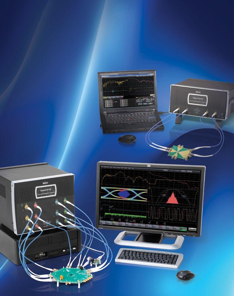

1 SPARQ High-bandwidth, Multi-port S-parameters


2 SPARQ: S-PARAmeteRS Quick Key Features Provides complete S-parameter measurements on up to 12 ports Mmeasures from DC to 40 GHz One-button-press internal OSLT calibration Analyzes in both frequency and time domain Produces mixed-mode and single-ended simulation-ready S-parameters Remove effects from fixtures, connectors and launches using either Time Gating or S-parameter de-embedding the SPARQ signal integrity network analyzers connect directly to the device under test (DUT) and to PC-based software through a single USB connection for quick, multi-port S-parameter measurements. SPARQ is the ideal instrument for characterizing multi-port devices common in signal integrity applications at a fraction of the cost of traditional methods. It is ideal for: Development of measurement-based simulation models Design validation Compliance testing High-performance TDR PCB testing Portable measurement requirements inherent TDR/TDT capability and preview modes for quick checks and debugging characterizes crosstalk of multi-lane differential structures Available at a fraction of the cost of other network analyzer solutions High-bandwidth, Multi-port S-parameters for the Masses S-parameter measurements are most often produced by the vector network analyzer (VNA), a difficult instrument that is beyond many budgets. SPARQ is very affordable and simplifies measurements, making S-parameters accessible to all. PC-based, Small and Portable Traditional instruments that produce S-parameters are large and fundamentally stationary. The SPARQ, in contrast, is small, lightweight and portable. It connects to any standard PC through a USB 2.0 interface, allowing SPARQ to run where computing power is easily upgraded. 2 visit teledynelecroy.com/sparq

 modules.")
3 S-parameters, Quick VNA measurements begin with the unpleasant and complex task of calibration. This involves multiple connections that can produce misleading results due to operator error. The SPARQ provides calibrated measurements with a single connection to the DUT and offers simple setup choices. Start and complete the entire measurement with a single button press. Internal Calibration SPARQ takes a revolutionary approach to calibration by building in calibration standards. This enables measurements to be made eliminates the need for additional expensive electronic calibration (ECAL) modules. Calibration proceeds quickly without user intervention, so one can calibrate often without resorting to the use of out-of-date saved calibrations. visit teledynelecroy.com/sparq 3


4 THE SIGNAL INteGRITY TOOLS you expect 1. Differential- and common-mode step response at input and output ports 1 2. Mixed-mode return loss to 40 GHz 3. TDR traces shown during measurement 4. Differential- and common-mode insertion loss to 40 GHz 2 5. Mode conversion step responses 6. Differential- and common-mode impedance vs. electrical length 7. Rise time normalization for all time domain results 3 8. Up to 16 measurements can be displayed simultaneously 9. Independent zoom control over each trace 10. Smith chart display alone, or with individual S-parameter plots The SPARQ signal integrity network analyzer displays time and frequency domain measurement results simultaneously. 4 visit teledynelecroy.com/sparq


5 4 5 Includes the Tools That You Expect A signal integrity network analyzer should include well-integrated tools for providing measurement and analysis in both time and frequency domains. Signal integrity requires more than just S-parameters; the time domain offers important insight as it shows the performance of the S-parameter models in simulation. 6 SPARQ includes standard all of the hardware and software tools needed to make signal integrity measurements right out of the box. 9 These tools include capabilities that cost extra on most instruments. Mixed-mode S-parameter conversion and port renumbering, passivity, reciprocity and causality enforcement are all standard. Built-in time domain views like impedance, rho, step response and impulse response are included as well. All time domain results can be normalized to your system rise time. The SPARQ hardware includes calibrated cables for each port, calibrated female 2.92 mm connectors for each port for adapting the connector gender, a universal wrench for holding most popular connector sizes, and a precision torque wrench. visit teledynelecroy.com/sparq 5


6 DesiGNed for Ease-OF-uSe The main SPARQ setup dialog shows all of the information needed to take S-parameter measurements in minutes. Streamlined Setup The simple setup shown in the main setup screen above is all that is needed to configure a SPARQ measurement. You provide the frequencies and number of ports and then go. Helper information like time length assist in frequency spacing choices, and DUT length mode choices control the pulser repetition rate for faster measurements. Various measurement sequence control modes allow for trade-offs between precision and speed, and helper information provides an estimate of the measurement time. All measurements proceed automatically without user intervention. Advanced screens are easily accessible for extra capability. Mixed-mode S-parameters Measurements encountered in signal integrity applications are often differential-mode or common-mode. SPARQ makes these mixed-mode measurements straightforward through the use of both graphical and tabular displays so there is no doubt about the format of the measurement results. SPARQ mixed-mode measurements are useful for determining the quality of high-speed channels. SPARQ easy to understand dialogs ensure that your mixed-mode S-parameters are properly formatted and avoids errors. The Next Generation of TDR/TDT The SPARQ is designed with different capabilities than instru ments you might have used in the past. The SPARQ s built-in calibration makes the measurement easy and 6 fast without trading off calibration accuracy. Older TDR/TDT based instruments claimed to be easier than frequency domain instruments, but sacrificed calibration for ease-of-use. The SPARQ is designed for high dynamic range with its unprecedented 6 ps pulser rise time and the Teledyne LeCroy patented coherent interleaved sampling (CIS) time base. This time base removes time base nonlinearity endemic to equivalent time sampling and enables fast averaging that is at least ten times faster than traditional TDR/TDT methods. The result is high-frequency measurements with much higher dynamic range than previously possible. visit teledynelecroy.com/sparq

7 Multi-Lane CrosstALk MeASurements 8 and 12-port SPARQs measure both near-end and far-end crosstalk (NEXT and FEXT). In this screenshot, both time-domain and S-parameters are displayed for the differential and common signal crosstalk. Characterize Crosstalk on Multi-lane Devices Crosstalk has become a challenging signal integrity effect due to the increasing use of multi-lane differential signaling. Multi-lane signaling has become pervasive, and is used in standards such as, PCIe Gen3, Serial Rapid IO, InfiniBand, and 40/100 GBASE Ethernet. The densities of signal lines and via fields in backplanes, connectors and interconnects has become a key source of signal integrity issues leading to closed eyes and excessive jitter. Signal integrity engineers find that they must attempt to both predict and understand these issues when designing multi-lane differential circuits and interconnects to avoid time-consuming design modifications and costly respins. The 12-port SPARQ can measure the full S-parameter matrix of 3-lane differential structures. Such measurements can be used in aggressor-victim-aggressor studies. 8-port SPARQs can measure structures with 2 differential lanes, for aggressor-victim simulations. With either the 8 or 12-port SPARQ, users can simultaneously measure differential near-end crosstalk (NEXT) and far-end crosstalk (FEXT), and view the results in both the time and frequency domains. visit teledynelecroy.com/sparq 7


8 simulation ready s-parameters From Measurement Directly to Simulation S-parameters present many difficulties for time domain simulators. These difficulties come from the two ends of the frequency spectrum. Lack of a DC point and truncation of the high frequency content causes simulation problems. Since it is based in the time domain, SPARQ provides a DC measurement point and 40 GHz frequency content so that simulators come up with the right answer. SPARQ provides enforcements of passivity, causality and reciprocity to ensure physical measurement results and provides time domain views so that time domain behavior is verified right at the time of measurement to ensure proper simulation results. Built-in De-embedding DUT connection and de-embedding present two major, related problems in S-parameter measurements. SPARQ allows the user to de-embed cables, adaptors and fixtures automatically from the measurements to extract the S-paramaters of the DUT. SPARQ utilizes its internal calibration capability and provides fully de-embedded device measurements; no external software tools are required. In situations where direct calibration to a new reference plane is desired, the user can use manual calibration techniques such as open-short-load-thru (OSLT) and save and recall these calibrations. Built-in Time Gating With the SPARQ, time gating can be used to determine the S-parameters of their DUT without effects caused by connectors and launches that are necessary to connect the DUT to a network analyzer. The gating can be performed using either an impedance peeling algorithm or by simple port extension. In addition to returning the S-parameters of the gated region, then S-parameters of the excluded regions are saved as S2P files. Pulser / Sampler CABLES ADAPTORS Sampler Internal Calibration Reference Plane Switch System & Internal Standards SPARQ PORTS Measurement Reference Plane Optional Manual Calibration Reference Plane FIXTURE De-embedded Measurement Reference Plane Optional Gated Reference Plane DUT Area of Interest DUT The SPARQ maintains three reference planes calibration, measurement, and de-embedded DUT. It keeps items that drift with time and temperature behind the calibration reference plane. SPARQ based S-parameters show strong correlation with simulations that use these models as shown in the above comparison of SPARQ time domain displays and a Simbeor simulation. Also shown are the SDD11 and SDD21 measurements acquired by the SPARQ. Simbeor is a trademark of Simberian Inc. 8 visit teledynelecroy.com/sparq


9 MEASURemeNTS RIGHT THE FIRST TIME Advanced Features that Prevent Mistakes and Wasted Time A frustrating situation is to find that after spending the time to calibrate and take S-parameter measurements, something is wrong either because of a mistake or a poor connection. Sometimes it is hours or days before the problem is detected; that is hours or days of suspect data in use. Because SPARQ is TDR/TDT based, it can be used to provide basic troubleshooting before you get too far into the measurement. By driving the SPARQ in its native TDR/TDT mode, engineers can pinpoint and isolate intermittent problems quickly. data and even change the measurement conditions like changing the number of frequency points or configuring for mixed-mode conversions. Results are recalculated based on the saved information without resorting to repeat measurements. Rugged and Reliable Design SPARQ utilizes high-frequency, highly reliable internal switches to route signals from pulser/sampler modules to internal calibration standards and to the device under test. SPARQ uses these switches to park the inputs to a 50 Ohm load during down time to help protect against electrostatic discharge (ESD). SPARQ utilizes precision 2.92 mm connectors at its connection ports. It ships with high phase-stability, low-loss cables to maintain its high dynamic range to 40 GHz. These cables provided with every unit are color-coded and calibrated. Color coding helps you visually keep track of correct cable connection. Of course, the user can use any type of cable or probe desired that connects via 2.92 mm or SMA. Raw TDR mode persistence showing added near- and far-end capacitance (upper grid) and the effect of wiggling a bad cable (lower grid). The SPARQ utilizes high-precision 2.92 mm connectors these can be mated with precision SMA connectors. SPARQ also offers preview modes: quick measurement modes that are useful for identification of measurement problems both in the time and frequency domain. A fully calibrated four-port preview measurement takes about three minutes from DUT connection to result display. Time-domain measurements mean that all of the measurement information is contained in acquisitions of step responses taken under various conditions. This is unlike frequency domain instruments which use frequency sweeps. The SPARQ allows the storing and recalling of all of the time-domain acquisitions performed during measurement so that later you can recall the 8 visit teledynelecroy.com/sparq 9


10 Signal integrity studio Key Features Seamless integration with Teledyne LeCroy SPARQ S-parameter measurements Full signal integrity analysis of equalized receiver signal Fast eye diagramming Advanced jitter analysis Co-simulation of measured and/or modeled network characteristics De-embedding and emulation of channel and fixture responses Emulation of CTLE, DFE & FFE equalizers and PLL Available as standalone software with USB license key or as an option installed on a Teledyne LeCroy SPARQ End-to-end Signal Integrity Workstation Signal Integrity Studio combines S-parameter measurements, channel and equalizer modeling and eye diagramming and jitter analysis in a single affordable software package. SI Studio is available as a standalone version or as an option for a Teledyne LeCroy SPARQ series network analyzer. With Signal Integrity Studio, users analyze the effects that impedance mismatches, losses, emphasis and equalization choices have on signal integrity characteristics of a device under test. S-parameters measured from an imported Touchstone file are used to emulate or de-embed a channel. Models for emphasis and equalization and a simulated waveform are configured by the user, and the resulting eye diagram can be viewed and analyzed to provide insight into the eye closure and jitter characteristics of the DUT and receiver design. See Effects of Measured S-parameters Immediately Signal Integrity Studio works seamlessly with the SPARQ v Series Signal Integrity Network Analyzers. S-parameters measured live by the SPARQ link directly to user s configuration for channel and fixture emulation or de-embedding configuration. As the SPARQ acquires new S-parameters, the application rapidly shows the affect of the newly acquired measurements. The SPARQ measures 40 GHz S-parameters with single button press operation at a fraction of the price of a VNA, and is available in 2-, 4-, 8- and 12-port versions. Channels are de-embedded or emulated using either modeled or measured S-parameters. 10 visit teledynelecroy.com/sistudio


11 Signal Integrity Studio enhances the modeling and simulation capabilities of the Teledyne LeCroy SPARQ application, adding eye and jitter measurements. Simulate Serial Data Patterns with Impairments Signal Integrity Studio analysis begins with a long serial data pattern output from the built-in simulator. Serial data waveform types include NRZ, RZ, bpnz and clock. Impairments such as vertical noise, horizontal jitter, overshoot/undershoot, periodic jitter aggressors and ISI can be configured. Waveforms previously saved on Teledyne LeCroy oscilloscopes can be used as a signal source. SI Studio utilizes a versatile built-in simulator as a signal source 11
, feed forward equalization (FFE) or decision feedback equalization (DFE) filters, and standard or customizable PLL settings.")

 are easily modeled via SI Studio s EyeDoctor II dialogs.")

12 From Measurement to Simulation Determine Optimal Equalizer Settings Users can open up closed eyes via a simple GUI for configuring pre-emphasis, de-emphasis, continuous time linear equalization (CTLE), feed forward equalization (FFE) or decision feedback equalization (DFE) filters, and standard or customizable PLL settings. Users can configure settings manually, or allow the software to configure automatically. Rapidly Measure Eye Diagrams The equalized signal is rapidly sliced into component unit intervals and an eye diagram created that is available for analysis. Users can display up to 11 eye diagram measurements, and perform mask testing to determine if the channel and equalizer settings result in a compliant eye. Equalizer and pre/de-emphasis (not shown) are easily modeled via SI Studio s EyeDoctor II dialogs. With SI Studio, users can see what the waveform would look like after channel impairments, and view the corresponding eye Analyze Jitter in Time and Frequency Domains Signal Integrity Studio has >15 views of jitter to give insight into the affects of jitter aggressors and consequences of signal integrity issues in the design of the channel and equalizer. Jitter analysis includes standard Tj, Rj and Dj dual-dirac model measurements, jitter spectrum, jitter histogram and more. A rich set of jitter and eye diagram analysis tools yield deep insight signal integrity issues of the device under test. 12 visit teledynelecroy.com/sistudio


13 Standalone Operation Customers who purchase SPARQ-SISTUDIO can access Signal Integrity Studio capabilities via a USB license key that ships with each order. Users can make measurements with the SPARQ, and then use the application software with its Studio features while untethered from the SPARQ. This mode of operation allows users to recalculate their S-parameters and re-analyze eye and jitter characteristics without the SPARQ hardware. Seamless Integration with Teledyne LeCroy SPARQ SI Studio is available as a software option for the Teledyne LeCroy SPARQ. Purchase SPARQ-SISTUDIO along with your SPARQ to give all users who connect to the SPARQ access to Signal Integrity Studio capabilities. When connected to a SPARQ that includes the SI STUDIO option, S-parameters can be measured and immediately used in simulations to study the signal integrity characteristics of a device under test. SI Studio Features Simulator Signal Type Signal Characteristics Emphasis De-embedding / Emulation Equalizer Serial Data: NRZ, RZ, bpnz and clock Frequency, Amplitude, Risetime, Overshoot, Undershoot, Spike, Vertical Noise, Horizontal jitter, Periodic Jitter, ISI Pre-emphasis or De-emphasis, Auto-add, Auto-remove, Custom setting of up to 8 taps Emulate or De-embed channel using Touchstone 1.0 S-parameter file measured on connected Teledyne LeCroy SPARQ or imported from SPARQ or VNA CTLE: Auto-set boost, or custom settings for DC gain, zero frequency, pole 1 frequency, pole 2 frequency FFE: Auto-find levels and tap values for user-selectable taps/precursor taps, or manually set values DFE: Auto-find levels and tap values for user-selectable taps/precursor taps, or manually set values and erasure delta PLL: Select from predefined software PLLs, including FC Golden, PCIe, DVI, FB-DIMM, USB3.0 SS or custom set Eye Measurements Eye Height Eye Crossing Mask Hits Avg Power Eye Width One Level Zero Level Eye Amplitude Mask outs BER Jitter Measurements Additional Scalar Waveforms Tj Jitter Spectrum Jitter CDF Rj Jitter vs Time (JitterTrack) Bathtub Curve Dj Dj Extraction Filtered Jitter DDj Jitter Distribution ISOBER Analysis DCD Qfit Pj ISI See Teledyne LeCroy SPARQ datasheet for additional software specifications visit teledynelecroy.com/sistudio 13

14 DesiGN VALiDAtiON to ComPLiance testing Compliance Testing SPARQ satisfies numerous transmitter, receiver, cable and fixture compliance testing requirements for standards such as: SATA TxRx Tests PCI Express SAS PHY Tests Fibre Channel USB DisplayPort HDMI SPARQ can perform all tests currently made with TDR or VNA instruments only easier. Some tests that SPARQ performs include: Impedance Return Loss Impedance Imbalance Insertion Loss Crosstalk (near- and far-end) Differential- to common-mode conversion Common- to differential-mode conversion Intra-pair skew Voltage transfer functions All measurements can be made in differential-mode, common-mode or single-ended, as applicable. Printed Circuit Board Testing Specifications for printed circuit boards are moving rapidly higher in frequency. The use of high-speed signaling on many boards involves more demanding tests than in the past. SPARQ measures all high-speed PCB specifications such as: Propagation velocity Dielectric constant Impedance Loss Skew SPARQ produced S-parameters are shown here working with Teledyne LeCroy oscilloscope based tools like the popular serial data analysis (SDA) and Eye Doctor tools in a co-simulation environment to predict the behavior and equalization requirements of a high-speed serial channel. Seamless Integration with Other Signal Integrity Test and Measurement Tools Teledyne LeCroy offers industry leading performance in digital oscilloscopes for signal integrity applications. The Eye Doctor analysis software utilizes S-parameters to de-embed and embed channels, connectors, cables and fixtures in serial data analysis. These tools operate directly on acquired waveforms in real time. When used in conjunction with Teledyne LeCroy s serial data analysis (SDA) software, the reference plane for eye diagram and jitter measurements can be moved to an ideal location (transmitter output) or to a standardized location for compliance testing (far-end of a compliance test channel). Additionally, SPARQ can aid in the design of transmitter and receiver equalizers by giving the user the ability to emulate the known channel response and simulate the effects of different equalizers. It performs all of these measurements for differentialand common-mode as well as single-ended, where applicable. SPARQ is much easier to operate than all other solutions and its 40 GHz upper frequency preserves your investment for many years. 14
15 specifications Model Specific Specifications Model 3012E 3008E 3004E 3002E 4004E 4002E 3002M 4002M Ports Calibration Internal, Automatic Manual Manual Operating Frequency DC - 30 GHz DC - 40 GHz DC - 30 GHz DC - 40 GHz S-parameter Measurements Single-ended and mixed mode (calculated) Calibration Method OSLT Connector Type 2.92 mm Standard Measurement Capability Frequency Domain Displays Magnitude, Phase, Real and Imaginary Time Domain Displays Impulse Response, Step Response, Rho, Z normalized to specified rise time Result Displays Up to 16 measurements displayed simultaneously Display Modes Smith Chart, single, dual, tandem, triple, quad, quattro, hex, octal De-embedding Modes User cables, adaptors, and optional fixture File Outputs Touchstone 1.0 Result Actions Auto-save and Pulser / Sampler and Time base Step Amplitude Rise Time Input Voltage Range Noise Repetition Rate Hardware Averaging Acquisition Rate Acquisition Duration Dynamic Range Time Base Type Equivalent Time Sample Rate Jitter Internal Switching Relays Frequency Rating Rated Life Insertion Loss VSWR Switching Variation Single Relay Port-port Isolation 200 mv (nominal top-base, 50 Ω termination) 6 ps 20 80% typical as measured by sampler +/-2V pk maximum (Exceeding may cause damage) -50 dbm (no averaging, bandwidth limited to 40 GHz) 5 MHz (normal DUT length mode) and 1 MHz (long DUT length 30% duty cycle Fast Averaging at 10 Million Points/Second Normal DUT Length Mode: 250 acquisitions/second, nominal Long DUT Length Mode: 50 acquisitions/second, nominal Normal DUT Length Mode: 50 ns; Long DUT Length Mode: 250 ns ƒ (ƒ) 20 Log(ƒ); (typical, ƒ in GHz; > 50 db at 40 GHz in `Normal sequence control mode) ƒ 1.33 (ƒ) 20 Log(ƒ); (typical, f in GHz; > 48 db at 30 GHz in Normal sequence control mode) Coherent Interleaved Sampling (CIS) GS/s 300 fs rms 40 GHz 2 million actuations per contact < 1.1 db at 40 GHz < 40 GHz Insertion loss: 0.05 db, 0.9, VSWR 40 GHz > GHz (pulser / sampler port-port isolation > GHz) Environmental Temperature (Operating) 5 C to 40 C (Internal Calibration valid 20 C 30 C) Humidity (Operating) Maximum relative humidity 80% for temperatures up to 30 C, decreasing linearly to 50% relative humidity at 40 C Altitude (Operating) Up to 10,000 ft (3,048 m) at or below 30 C Physical Dimensions Dimensions Shipping Dimensions H x W x 13.6 D (282 x 332 x 345 mm) 20 7/8 H x 21 1/16 W x 19 D (530.2 x 534 x mm) 7 H x 13 W x 13 D (178 x 330 x 330 mm) 12 H x 25 W x 20.5 D (305 x 635 x 521 mm) Weight 26.1 lbs (11.84 kg) 23.2 lbs (10.52 kg) 17 lbs. (7.711 kg) lbs. (6.70 kg) Shipping Weight lbs (16.21 kg) 32.5 lbs (14.75 kg) 29 lbs. (13.17 kg) (12.14 kg) Power Requirements Voltage Max. Power Consumption 100 to 240 VAC (±10%) at 50/60 Hz; Automatic AC voltage selection 80 W (80 VA) (Operating Mode), 7 W (Standby) Recommended PC Configuration Operating System Microsoft Vista or Windows 7, 64-bit (Note: The SPARQ application will run on Windows 32 bit operating systems, but S-parameter calculation time will be impaired) Processor Intel Core i7 or better Intel Core GHz or better Memory 4 GB RAM or better Hard Drive 2 GB available free space Display Resolution 1280 x 780 Connectivity USB 2.0 High-speed 15

16 ORDERING INFORMAtiON Product Description Product Code s 30 GHz, 12-port, Internal Calibration, SPARQ-3012E 30 GHz, 8-port, Internal Calibration, SPARQ-3008E 30 GHz, 4-port, Internal Calibration, SPARQ-3004E 30 GHz, 2-port, Internal Calibration, SPARQ-3002E 30 GHz, 2-port, Manual Calibration, SPARQ-3002M 40 GHz, 4-port, Internal Calibration, SPARQ-4004E 40 GHz, 2-port, Internal Calibration, SPARQ-4002E 40 GHz, 2-port, Manual Calibration, SPARQ-4002M Warranty and Service 3-year Warranty Under Terms of Instrument Use Customer Service Teledyne LeCroy instruments are designed, built and tested to ensure high reliability. In the unlikely event you experience difficulties our instruments are warranted for three years under normal usage conditions. Teledyne LeCroy provides optional services to keep your SPARQ providing accurate measurements year after year. This warranty includes: No charge for return shipping Long-term 7-year support Upgrade to latest software at no charge Optional service contracts for SPARQ calibration and extended warranty Economically priced upgrades to higher port-count models Options and Accessories Signal Integrity Studio SPARQ-SISTUDIO 2 x 40 GHz Cables SPARQ-C402 4 x 40 GHz Cables SPARQ-C404 Manual Calibration Kit SPARQ-OSLT Soft Carrying Case SPARQ-SFTC Included with Standard Configuration Color-coded, serialized, calibrated cables, one per port Accessory Kit including female 2.92 mm adaptors (one per port), universal wrench, torque wrench, and USB memory stick containing software and calibration data Calibration and Performance Certificate Power Cord (country appropriate) USB Cable Soft Carrying Case (2 and 4-port models) LeCroy teledynelecroy.com Local sales offices are located throughout the world. Visit our website to find the most convenient location by Teledyne LeCroy. All rights reserved. Specifications, prices, availability, and delivery subject to change without notice. Product or brand names are trademarks or requested trademarks of their respective holders. sparq_ds-15oct12
SDAIII-CompleteLinQ Multi-Lane Serial Data, Noise and Crosstalk Analysis
 SDAIII-CompleteLinQ Multi-Lane Serial Data, Noise and Crosstalk Analysis TOOLS TO MEET SERIAL DATA ANALYSIS CHALLENGES Key Features Most complete jitter decomposition, eye diagram and analysis tools Up
Eye Doctor II Advanced Signal Integrity Tools
 Eye Doctor II Advanced Signal Integrity Tools EYE DOCTOR II ADVANCED SIGNAL INTEGRITY TOOLS Key Features Eye Doctor II provides the channel emulation and de-embedding tools Adds precision to signal integrity
De-embedding Gigaprobes Using Time Domain Gating with the LeCroy SPARQ
 De-embedding Gigaprobes Using Time Domain Gating with the LeCroy SPARQ Dr. Alan Blankman, Product Manager Summary Differential S-parameters can be measured using the Gigaprobe DVT30-1mm differential TDR
Electrical Sampling Modules Datasheet 80E11 80E11X1 80E10B 80E09B 80E08B 80E07B 80E04 80E03 80E03-NV
 Electrical Sampling Modules Datasheet 80E11 80E11X1 80E10B 80E09B 80E08B 80E07B 80E04 80E03 80E03-NV The DSA8300 Series Sampling Oscilloscope, when configured with one or more electrical sampling modules,
Draft Baseline Proposal for CDAUI-8 Chipto-Module (C2M) Electrical Interface (NRZ)
 Electrical Interface (NRZ)") Draft Baseline Proposal for CDAUI-8 Chipto-Module (C2M) Electrical Interface (NRZ) Authors: Tom Palkert: MoSys Jeff Trombley, Haoli Qian: Credo Date: Dec. 4 2014 Presented: IEEE 802.3bs electrical interface
Draft Baseline Proposal for CDAUI-8 Chipto-Module (C2M) Electrical Interface (NRZ) Authors: Tom Palkert: MoSys Jeff Trombley, Haoli Qian: Credo Date: Dec. 4 2014 Presented: IEEE 802.3bs electrical interface
Agilent MOI for HDMI 1.4b Cable Assembly Test Revision Jul 2012
 Revision 1.11 19-Jul 2012 Agilent Method of Implementation (MOI) for HDMI 1.4b Cable Assembly Test Using Agilent E5071C ENA Network Analyzer Option TDR 1 Table of Contents 1. Modification Record... 4 2.
WAVEJET 300 SERIES OSCILLOSCOPES. Unmatched Performance, Portability, and Value
 WAVEJET 300 SERIES OSCILLOSCOPES Unmatched Performance, Portability, and Value 1 WAVEJET 300 SERIES Unique Capabilities in a Low Bandwidth Oscilloscope The WaveJet 300 Series features unmatched performance
Electrical Sampling Modules
 Electrical Sampling Modules 80E11 80E11X1 80E10B 80E09B 80E08B 80E07B 80E04 80E03 80E03-NV Datasheet Applications Impedance Characterization and S-parameter Measurements for Serial Data Applications Advanced
Practical De-embedding for Gigabit fixture. Ben Chia Senior Signal Integrity Consultant 5/17/2011
 Practical De-embedding for Gigabit fixture Ben Chia Senior Signal Integrity Consultant 5/17/2011 Topics Why De-Embedding/Embedding? De-embedding in Time Domain De-embedding in Frequency Domain De-embedding
Combating Closed Eyes Design & Measurement of Pre-Emphasis and Equalization for Lossy Channels
 Combating Closed Eyes Design & Measurement of Pre-Emphasis and Equalization for Lossy Channels Why Test the Receiver? Serial Data communications standards have always specified both the transmitter and
Combating Closed Eyes Design & Measurement of Pre-Emphasis and Equalization for Lossy Channels
 Combating Closed Eyes Design & Measurement of Pre-Emphasis and Equalization for Lossy Channels Why Test the Receiver? Serial Data communications standards have always specified both the transmitter and
WAVEJET 300 SERIES OSCILLOSCOPES. New Cover to Come. Unmatched Performance, Portability, and Value
 WAVEJET 300 SERIES OSCILLOSCOPES New Cover to Come Unmatched Performance, Portability, and Value ALL THE TOOLS YOU NEED Automatic Measurements Save time making measurements on your signals by using the
Portable Performance for Debug and Validation
 WaveJet 300A Oscilloscopes 100 MHz 500 MHz Portable Performance for Debug and Validation A UNIQUE TOOLSET FOR PORTABLE OSCILLOSCOPES Key Features 100 MHz, 200 MHz, 350 MHz and 500 MHz bandwidths Sample
Keysight Technologies M8048A ISI Channels
 Keysight Technologies M8048A ISI Channels Master Your Next Designs Data Sheet Key features Emulate a wide range of channel loss with cascadable ISI traces with fine resolution 4 short (7.7 to 12.8 ) and
GT Dual-Row Nano Vertical SMT High Speed Characterization Report For Differential Data Applications
 GT-16-95 Dual-Row Nano Vertical SMT For Differential Data Applications 891-011-15S Vertical SMT PCB 891-001-15P Cable Mount Revision History Rev Date Approved Description A 6/3/2016 R. Ghiselli/D. Armani
GT Dual-Row Nano Vertical Thru-Hole High Speed Characterization Report For Differential Data Applications
 GT-16-97 Dual-Row Nano Vertical Thru-Hole For Differential Data Applications 891-007-15S Vertical Thru-Hole PCB 891-001-15P Cable Mount Revision History Rev Date Approved Description A 8/31/2016 R. Ghiselli/G.
WAVEEXPERT SERIES OSCILLOSCOPES WE 9000 NRO 9000 SDA 100G. The World s Fastest Oscilloscope
 WAVEEXPERT SERIES OSCILLOSCOPES WE 9000 NRO 9000 SDA 100G The World s Fastest Oscilloscope The Fastest Oscilloscope in the Marketplace The WaveExpert and SDA 100G are the first instruments to combine the
SignalCorrect Software and TCS70902 Calibration Source Option SC SignalCorrect software
 SignalCorrect Software and TCS70902 Calibration Source Option SC SignalCorrect software Eye of signal after de-embed using SignalCorrect Features and benefits Measurement and de-embed: Characterize cables
Keysight Method of Implementation (MOI) for VESA DisplayPort (DP) Standard Version 1.3 Cable-Connector Compliance Tests Using E5071C ENA Option TDR
 for VESA DisplayPort (DP) Standard Version 1.3 Cable-Connector Compliance Tests Using E5071C ENA Option TDR") Revision 1.00 February 27, 2015 Keysight Method of Implementation (MOI) for VESA DisplayPort (DP) Standard Version 1.3 Cable-Connector Compliance Tests Using E5071C ENA Option TDR 1 Table of Contents 1.
Revision 1.00 February 27, 2015 Keysight Method of Implementation (MOI) for VESA DisplayPort (DP) Standard Version 1.3 Cable-Connector Compliance Tests Using E5071C ENA Option TDR 1 Table of Contents 1.
PicoScope 9200A PC Sampling Oscilloscopes for Windows PCs
 PicoScope 9200A PC Sampling Oscilloscopes for Windows PCs Signal characterization Pre-compliance testing Electrical TDR and TDT Production pass/fail testing Complete sampling oscilloscopes for your PC
USB-TG124A Tracking Generator User Manual
 USB-TG124A Tracking Generator User Manual Signal Hound USB-TG124A User Manual 2017, Signal Hound, Inc. 35707 NE 86th Ave La Center, WA 98629 USA Phone 360.263.5006 Fax 360.263.5007 This information is
Serial Data Link Analysis Visualizer (SDLA Visualizer) Option SDLA64, DPOFL-SDLA64
 Option SDLA64, DPOFL-SDLA64") Serial Data Link Analysis Visualizer (SDLA Visualizer) Option SDLA64, DPOFL-SDLA64 SDLA Visualizer and DPOJET with simultaneous views of a PCI Express 3.0 acquired signal, signal after compliance channel
Serial Data Link Analysis Visualizer (SDLA Visualizer) Option SDLA64, DPOFL-SDLA64 SDLA Visualizer and DPOJET with simultaneous views of a PCI Express 3.0 acquired signal, signal after compliance channel
QPHY-USB3 USB3.0 Serial Data Operator s Manual
 QPHY-USB3 USB3.0 Serial Data Operator s Manual Revision A April, 2009 Relating to the Following Release Versions: Software Option Rev. 5.8 USB3 Script Rev. 1.0 Style Sheet Rev. 1.2 LeCroy Corporation 700
Digital Storage Oscilloscopes 2550 Series
 Data Sheet Digital Storage Oscilloscopes 2550 Series The 2550 series digital storage oscilloscopes provide high performance and value in 2-channel and 4-channel configurations. With bandwidth from 70 MHz
The Measurement Tools and What They Do
 2 The Measurement Tools The Measurement Tools and What They Do JITTERWIZARD The JitterWizard is a unique capability of the JitterPro package that performs the requisite scope setup chores while simplifying
Vector Network Analyzer TTR503A/TTR506A USB Vector Network Analyzer Preliminary Datasheet. Subject to change.
 Vector Network Analyzer TTR503A/TTR506A USB Vector Network Analyzer Preliminary Datasheet. Subject to change. Applications Academic/Education Design, development and manufacturing of passive and active
PicoScope 9200A PC Sampling Oscilloscopes for Windows PCs
 PicoScope 9200A PC Sampling Oscilloscopes for Windows PCs Pre-compliance testing Electrical TDR and TDT Production pass/fail testing Complete sampling oscilloscopes for your PC 12 GHz bandwidth on 2 channels
Why Engineers Ignore Cable Loss
 Why Engineers Ignore Cable Loss By Brig Asay, Agilent Technologies Companies spend large amounts of money on test and measurement equipment. One of the largest purchases for high speed designers is a real
Agilent N4876A 28 Gb/s Multiplexer 2:1
 Agilent N4876A 28 Gb/s Multiplexer 2:1 Data Sheet Revision 1.0 Features and Benefits Variable data rate up to 28.4 Gb/s Multiplexes two generator channels Front-end box for J-BERT or ParBERT Control via
New Serial Link Simulation Process, 6 Gbps SAS Case Study
 ew Serial Link Simulation Process, 6 Gbps SAS Case Study Donald Telian SI Consultant Session 7-TH2 Donald Telian SI Consultant About the Authors Donald Telian is an independent Signal Integrity Consultant.
Brian Holden Kandou Bus, S.A. IEEE GE Study Group September 2, 2013 York, United Kingdom
 Simulation results for NRZ, ENRZ & PAM-4 on 16-wire full-sized 400GE backplanes Brian Holden Kandou Bus, S.A. brian@kandou.com IEEE 802.3 400GE Study Group September 2, 2013 York, United Kingdom IP Disclosure
Model 7330 Signal Source Analyzer Dedicated Phase Noise Test System V1.02
 Model 7330 Signal Source Analyzer Dedicated Phase Noise Test System V1.02 A fully integrated high-performance cross-correlation signal source analyzer from 5 MHz to 33+ GHz Key Features Complete broadband
Agilent 87075C 75 Ohm Multiport Test Sets for use with Agilent E5061A ENA-L Network Analyzers
 Agilent 87075C 75 Ohm Multiport Test Sets for use with Agilent E5061A ENA-L Network Analyzers Technical Overview Focus on testing, not reconnecting! Maximize production throughput of cable-tv multiport
Boosting Performance Oscilloscope Versatility, Scalability
 Boosting Performance Oscilloscope Versatility, Scalability Rising data communication rates are driving the need for very high-bandwidth real-time oscilloscopes in the range of 60-70 GHz. These instruments
Agilent 87075C Multiport Test Set Product Overview
 Agilent 87075C Multiport Test Set Product Overview A complete 75 ohm system for cable TV device manufacturers Now, focus on testing, not reconnecting! For use with the Agilent 8711 C-Series of network
PAM4 signals for 400 Gbps: acquisition for measurement and signal processing
 TITLE PAM4 signals for 400 Gbps: acquisition for measurement and signal processing Image V1.00 1 Introduction, content High speed serial data links are in the process in increasing line speeds from 25
立肯科技 LeColn Technology
 DisplayPort PHY Validation 立肯科技 LeColn Technology 1 DisplayPort Basics Maximum bit rate DP1.2b 1.62Gb/s( RBR = reduced bit rate) 2.7Gb/s( HBR = high bit rate) 5.4Gb/s( HBR2 =high bit rate 2) DP1.3/1.4
Datasheet SHF A
 SHF Communication Technologies AG Wilhelm-von-Siemens-Str. 23D 12277 Berlin Germany Phone +49 30 772051-0 Fax ++49 30 7531078 E-Mail: sales@shf.de Web: http://www.shf.de Datasheet SHF 19120 A 2.85 GSa/s
Switching Solutions for Multi-Channel High Speed Serial Port Testing
 Switching Solutions for Multi-Channel High Speed Serial Port Testing Application Note by Robert Waldeck VP Business Development, ASCOR Switching The instruments used in High Speed Serial Port testing are
WAVEEXPERT 100H. Wide Bandwidth Oscilloscopes for the Next Generation Serial Data Standards
 WAVEEXPERT 100H Wide Bandwidth Oscilloscopes for the Next Generation Serial Data Standards The New WaveExpert 100H Sampling Oscilloscope the Complete Workstation for Optimizing Serial Data Signal Integrity
MSO-28 Oscilloscope, Logic Analyzer, Spectrum Analyzer
 Link Instruments Innovative Test & Measurement solutions since 1986 Store Support Oscilloscopes Logic Analyzers Pattern Generators Accessories MSO-28 Oscilloscope, Logic Analyzer, Spectrum Analyzer $ The
JD725A Cable and Antenna Analyzer - Dual Port
 COMMUNICATIONS TEST & MEASUREMENT SOLUTIONS JD725A Cable and Antenna Analyzer - Dual Port Key Features Portable and lightweight handheld instrument Built-in wireless frequency bands as well as the most
PCIe: EYE DIAGRAM ANALYSIS IN HYPERLYNX
 PCIe: EYE DIAGRAM ANALYSIS IN HYPERLYNX w w w. m e n t o r. c o m PCIe: Eye Diagram Analysis in HyperLynx PCI Express Tutorial This PCI Express tutorial will walk you through time-domain eye diagram analysis
Agilent N4876A 28 Gb/s Multiplexer 2:1
 Agilent N4876A 28 Gb/s Multiplexer 2:1 Data Sheet, Revision 1.1 Features and Benefits Variable data rate up to 28.4 Gb/s Multiplexes two generator channels Front-end box for J-BERT or ParBERT Control via
Analog Dual-Standard Waveform Monitor
 Test Equipment Depot - 800.517.8431-99 Washington Street Melrose, MA 02176 - TestEquipmentDepot.com Analog Dual-Standard Waveform Monitor 1741C Datasheet Additional Analysis Features Timing Display for
PicoScope 9200A PC Sampling Oscilloscopes for Windows PCs
 PicoScope 9200A PC Sampling Oscilloscopes for Windows PCs Signal characterization Pre-compliance testing Electrical TDR and TDT Production pass/fail testing Complete sampling oscilloscopes for your PC
100G EDR and QSFP+ Cable Test Solutions
 100G EDR and QSFP+ Cable Test Solutions (IBTA, 100GbE, CEI) DesignCon 2017 James Morgante Anritsu Company Presenter Bio James Morgante Application Engineer Eastern United States james.morgante@anritsu.com
7000 Series Signal Source Analyzer & Dedicated Phase Noise Test System
 7000 Series Signal Source Analyzer & Dedicated Phase Noise Test System A fully integrated high-performance cross-correlation signal source analyzer with platforms from 5MHz to 7GHz, 26GHz, and 40GHz Key
NVISION Compact Space and cost efficient utility routers
 Space and cost efficient utility routers DESCRIPTION The NVISION Compact range is highly versatile, and ideally suited to utility routing applications. They are available for all core formats, including
USB Smart Power Sensor
 50Ω -30 dbm to +20 dbm, 1 MHz to 8000 MHz The Big Deal Fast measurement speed, 10 msec USB HID device compatible with 32/64 Bit operating systems Includes Measurement Application GUI (Graphical User Interface)
Agilent E4887A HDMI TMDS Signal Generator Platform
 Agilent E4887A HDMI TMDS Signal Generator Platform Data Sheet Version 1.9 Preliminary E4887A- 007 E4887A- 037 E4887A- 003 Page Convenient Compliance Testing and Characterization of HDMI 1.3 Devices The
RF Semiconductor Test AXRF RF Port Upgrade Kits
 RF Semiconductor Test AXRF RF Port Upgrade Kits 2017 Datasheet The most important thing we build is trust Overview AXRF RF Port Upgrade Kits are designed to improve and extend the capability of an existing
PicoScope 6407 Digitizer
 YE AR PicoScope 6407 Digitizer HIGH PERFORMANCE USB DIGITIZER Programmable and Powerful 1 GHz bandwidth 1 GS buffer size 5 GS/s real-time sampling Advanced digital triggers Built-in function generator
PicoScope 9300 Series migration guide
 sampling oscilloscopes since 2009 The 9300 Series is a leading-edge product family resulting from a long program of product development. From late 2017, in the process of adding new 15 GHz and 25 GHz models,
Expect to Make Waves.
 Expect to Make Waves. The New Oscilloscope Large 10.4" LCD touch screen Long capture time Extensive communication capabilities www.lecroy.com The New Oscillos From its large 10.4" LCD touch screen to its
SV1C Personalized SerDes Tester
 SV1C Personalized SerDes Tester Data Sheet SV1C Personalized SerDes Tester Data Sheet Revision: 1.0 2013-02-27 Revision Revision History Date 1.0 Document release Feb 27, 2013 The information in this
PicoScope 6407 Digitizer
 YE AR HIGH PERFORMANCE USB DIGITIZER Programmable and Powerful 1 GHz bandwidth 1 GS buffer size 5 GS/s real-time sampling Advanced digital triggers Built-in function generator USB-connected Signals Analysis
FCPM-6000RC. Mini-Circuits P.O. Box , Brooklyn, NY (718)
") USB / Ethernet Integrated Frequency Counter & Power Meter 50Ω -30 dbm to +20 dbm, 1 MHz to 6000 MHz The Big Deal Automatically synchronized power & frequency measurements USB and Ethernet control Includes
USB / Ethernet Integrated Frequency Counter & Power Meter 50Ω -30 dbm to +20 dbm, 1 MHz to 6000 MHz The Big Deal Automatically synchronized power & frequency measurements USB and Ethernet control Includes
20 GHz bandwidth 17.5 ps rise time
 PicoScope 9300 Series THE NEW FACE OF SAMPLING OSCILLOSCOPES 20 GHz bandwidth 17.5 ps rise time A LONG LIST OF FEATURES 1 MS/s sequential sampling - the industry s fastest NRZ and RZ eye plots and measurements
MS-32 OSCILLOSCOPE MIXED SIGNAL OPTION. Add 32 Digital Channels to a 4 Channel Oscilloscope
 MS-32 OSCILLOSCOPE MIXED SIGNAL OPTION Add 32 Digital Channels to a 4 Channel Oscilloscope 4 Analog + 32 Digital Channel Capability LeCroy introduces the first oscilloscope solution to combine 4 analog
SI Analysis & Measurement as easy as mobile apps ISD, ADK, X2D2
 SI Analysis & Measurement as easy as mobile apps ISD, ADK, X2D2 Ching-Chao Huang huang@ataitec.com Outline Can SI tools be made like mobile apps? Introduction of AtaiTec SI software Most applications in
2x2 HDMI Matrix Switch - 4K with Fast Switching and Auto-Sensing
 2x2 HDMI Matrix Switch - 4K with Fast Switching and Auto-Sensing Product ID: VS222HD4K Save time and hassle by automatically switching between your HDMI audio/video sources. This 2x2 HDMI matrix switcher
Keysight N1055A Remote Head Module 35/50 GHz 2/4 Port TDR/TDT
 Keysight N1055A Remote Head Module 35/50 GHz 2/4 Port TDR/TDT For the 86100D DCA-X Series Oscilloscope Mainframe Data Sheet Engineered for easy, accurate impedance and S-parameter measurements on multi-port
Senior Project Manager / AEO
 Kenny Liao 2018.12.18&20 Senior Project Manager / AEO Measurement Demo Prepare instrument for measurement Calibration Fixture removal Conclusion What next? Future trends Resources Acquire channel data
Complete sampling oscilloscope for your PC
 PicoScope 9200 Series PC SAMPLING OSCILLOSCOPES Complete sampling oscilloscope for your PC 12 GHz bandwidth on 2 channels Dual timebase from 10 ps/div Up to 10 GHz trigger bandwidth Optical and electrical
Using Allegro PCB SI GXL to Make Your Multi-GHz Serial Link Work Right Out of the Box
 Using Allegro PCB SI GXL to Make Your Multi-GHz Serial Link Work Right Out of the Box Session 8.11 - Hamid Kharrati - A2e Technologies Agenda About the Project Modeling the System Frequency Domain Analysis
Comparison of NRZ, PR-2, and PR-4 signaling. Qasim Chaudry Adam Healey Greg Sheets
 Comparison of NRZ, PR-2, and PR-4 signaling Presented by: Rob Brink Contributors: Pervez Aziz Qasim Chaudry Adam Healey Greg Sheets Scope and Purpose Operation over electrical backplanes at 10.3125Gb/s
Signal Stability Analyser
 Signal Stability Analyser o Real Time Phase or Frequency Display o Real Time Data, Allan Variance and Phase Noise Plots o 1MHz to 65MHz medium resolution (12.5ps) o 5MHz and 10MHz high resolution (50fs)
Logic Analysis Basics
 Logic Analysis Basics September 27, 2006 presented by: Alex Dickson Copyright 2003 Agilent Technologies, Inc. Introduction If you have ever asked yourself these questions: What is a logic analyzer? What
Logic Analysis Basics
 Logic Analysis Basics September 27, 2006 presented by: Alex Dickson Copyright 2003 Agilent Technologies, Inc. Introduction If you have ever asked yourself these questions: What is a logic analyzer? What
R&S ZN-Z85 Switch Matrix Specifications
 R&S ZN-Z85 Switch Matrix Specifications Data Sheet Version 01.02 CONTENTS Definitions... 3 Block diagrams... 4 Specifications... 5 General features... 5 Performance data... 5 Remote control... 5 Switching
ELECTRICAL PERFORMANCE REPORT
 CIRCUITS & DESIGN ELECTRICAL PERFORMANCE REPORT DENSIPAC 4 ROW Date: 06-12-2006 Circuits & Design EMEA Circuits & Design 1/21 06/12/2006 1 INTRODUCTION... 3 2 CONNECTORS, TEST BOARDS AND TEST EQUIPMENT...
Advanced Test Equipment Rentals ATEC (2832)
") E stablished 1981 Advanced Test Equipment Rentals www.atecorp.com 800-404-ATEC (2832) Technical Datasheet Scalar Network Analyzer Model 8003-10 MHz to 40 GHz The Giga-tronics Model 8003 Precision Scalar
E stablished 1981 Advanced Test Equipment Rentals www.atecorp.com 800-404-ATEC (2832) Technical Datasheet Scalar Network Analyzer Model 8003-10 MHz to 40 GHz The Giga-tronics Model 8003 Precision Scalar
SDLA Visualizer Serial Data Link Analysis Visualizer Software Printable Application Help
 SDLA Visualizer Serial Data Link Analysis Visualizer Software Printable Application Help *P076017306* 076-0173-06 SDLA Visualizer Serial Data Link Analysis Visualizer Software Printable Application Help
40 Gb/s PatternPro Programmable Pattern Generator PPG4001 Datasheet
 40 Gb/s PatternPro Programmable Pattern Generator PPG4001 Datasheet Applications Semiconductor device testing Optical component testing Transceiver module testing The Tektronix PPG4001 PatternPro programmable
PicoScope 9200 Series
 PicoScope 9200 Series PC SAMPLING OSCILLOSCOPES Complete sampling oscilloscope for your PC 12 GHz bandwidth on 2 channels Dual timebase from 10 ps/div Up to 10 GHz trigger bandwidth Optical and electrical
Microwave Interconnect Testing For 12G-SDI Applications
 DesignCon 2016 Microwave Interconnect Testing For 12G-SDI Applications Jim Nadolny, Samtec jim.nadolny@samtec.com Corey Kimble, Craig Rapp Samtec OJ Danzy, Mike Resso Keysight Boris Nevelev Imagine Communications
R&S ZVA110 Vector Network Analyzer Specifications
 ZVA110_dat-sw_en_5214-4813-22_cover.indd 1 Data Sheet 04.00 Test & Measurement R&S ZVA110 Vector Network Analyzer Specifications 15.11.2013 14:42:28 CONTENTS Definitions... 3 Specifications... 4 Overview...
Emphasis, Equalization & Embedding
 Emphasis, Equalization & Embedding Cleaning the Rusty Channel Gustaaf Sutorius Application Engineer Agilent Technologies gustaaf_sutorius@agilent.com Dr. Thomas Kirchner Senior Application Engineer Digital
Analyze Frequency Response (Bode Plots) with R&S Oscilloscopes Application Note
 with R&S Oscilloscopes Application Note") Analyze Frequency Response (Bode Plots) with R&S Oscilloscopes Application Note Products: R&S RTO2002 R&S RTO2004 R&S RTO2012 R&S RTO2014 R&S RTO2022 R&S RTO2024 R&S RTO2044 R&S RTO2064 This application
Analyze Frequency Response (Bode Plots) with R&S Oscilloscopes Application Note Products: R&S RTO2002 R&S RTO2004 R&S RTO2012 R&S RTO2014 R&S RTO2022 R&S RTO2024 R&S RTO2044 R&S RTO2064 This application
Calibrate, Characterize and Emulate Systems Using RFXpress in AWG Series
 Calibrate, Characterize and Emulate Systems Using RFXpress in AWG Series Introduction System designers and device manufacturers so long have been using one set of instruments for creating digitally modulated
Optimizing BNC PCB Footprint Designs for Digital Video Equipment
 Optimizing BNC PCB Footprint Designs for Digital Video Equipment By Tsun-kit Chin Applications Engineer, Member of Technical Staff National Semiconductor Corp. Introduction An increasing number of video
Basic RF Amplifier Measurements using the R&S ZNB Vector Network Analyzer and SMARTerCal. Application Note
 Basic RF Amplifier Measurements using a R&S ZNB Analyzer and SMARTerCal Mark Bailey 2013-03-05, 1ES, Version 1.0 Basic RF Amplifier Measurements using the R&S ZNB Vector Network Analyzer and SMARTerCal.
Thank you for purchasing a LeCroy Zi Oscilloscope Synchronization ProBus Module (Zi 8CH SYNCH module).
.") Introduction Instructions Thank you for purchasing a LeCroy Zi Oscilloscope Synchronization ProBus Module (Zi 8CH SYNCH module). The module is designed for use on 4 30 GHz WaveMaster 8 Zi oscilloscopes
Introduction Instructions Thank you for purchasing a LeCroy Zi Oscilloscope Synchronization ProBus Module (Zi 8CH SYNCH module). The module is designed for use on 4 30 GHz WaveMaster 8 Zi oscilloscopes
Agilent N6467A BroadR-Reach Compliance Test Application. Methods of Implementation
 Agilent N6467A BroadR-Reach Compliance Test Application Methods of Implementation s1 Notices Agilent Technologies, Inc. 2013 No part of this manual may be reproduced in any form or by any means (including
N1000A DCA-X. Wide Bandwidth Oscilloscope Mainframe and Modules. Find us at Page 1
 N1000A DCA-X Wide Bandwidth Oscilloscope Mainframe and Modules Find us at www.keysight.com Page 1 Table of Contents Introduction... 3 N1000A DCA-X Specifications... 4 Module Selection Guide... 12 Module
Transcom Instruments. Product Brochure TRANSCOM INSTRUMENTS. Product Brochure. 1
 TRANSCOM INSTRUMENTS Product Brochure Transcom Instruments Product Brochure www.transcomwireless.com 1 T5000 Series Bench-top Vector Network Analyzer Overview T5000 Series Bench-top Vector Network Analyzer
Spectrum Analyzer 1.6 GHz 3 GHz R&S HMS-X
 HMS-X_bro_de-en_3607-0181-3X_v0200.indd 1 Product Brochure 02.00 Test & Measurement Spectrum Analyzer 1.6 GHz 3 GHz R&S HMS-X 15.03.2016 15:24:06 1 Basic Unit + 3 Options Key facts Frequency range: 100
PBR-310C E-BERT. 10Gb/s BERT System with Eye Diagram Tracer
 PBR-310C E-BERT 10Gb/s BERT System with Eye Diagram Tracer rate from 8.5~11.1Gb/s and extend data rate down to 125M~5Gb/s Support up to four channels Eye Diagram and Mask Test* Eye Contour and Histogram*
RF Characterization Report
 BNC7T-J-P-xx-ST-EMI BNC7T-J-P-xx-RD-BH1 BNC7T-J-P-xx-ST-TH1 BNC7T-J-P-xx-ST-TH2D BNC7T-J-P-xx-RA-BH2D Mated with: RF179-79SP1-74BJ1-0300 Description: 75 Ohm BNC Board Mount Jacks Samtec, Inc. 2005 All
PicoScope 2000 Series PC Oscilloscopes
 PicoScope 2000 Series PC Oscilloscopes User guide I PicoScope 2000 Series User Guide Table of Contents 1 Introduction...2...2 1 Overview...2 2 Safety symbols...3 3 Safety warning...3 4 FCC notice 5 CE
Next Generation Ultra-High speed standards measurements of Optical and Electrical signals
 Next Generation Ultra-High speed standards measurements of Optical and Electrical signals Apr. 2011, V 1.0, prz Agenda Speeds above 10 Gb/s: Transmitter and Receiver test setup Transmitter Test 1,2 : Interconnect,
Benefits of the R&S RTO Oscilloscope's Digital Trigger. <Application Note> Products: R&S RTO Digital Oscilloscope
 Benefits of the R&S RTO Oscilloscope's Digital Trigger Application Note Products: R&S RTO Digital Oscilloscope The trigger is a key element of an oscilloscope. It captures specific signal events for detailed
R&S ZVA-Zxx Millimeter-Wave Converters Specifications
 R&S ZVA-Zxx Millimeter-Wave Converters Specifications Data Sheet Version 19.00 CONTENTS Definitions... 3 General information... 4 Specifications... 5 Test port... 5 Source input (RF IN)... 5 Local oscillator
Complete sampling oscilloscope for your PC
 Distribution in the UK & Ireland Characterisation, Measurement & Analysis Lambda Photometrics Limited Lambda House Batford Mill Harpenden Herts AL5 5BZ United Kingdom E: info@lambdaphoto.co.uk W: www.lambdaphoto.co.uk
ScopeMeter 190 Series Specifications
 Seite 1 von 7 ScopeMeter 190 Series Specifications Product Home Features Specifications Models, Options & Accessories Oscilloscope Mode Meter Mode Recorder Mode General Specifications Oscilloscope Mode
Agilent N9355/6 Power Limiters 0.01 to 18, 26.5 and 50 GHz
 Agilent N9355/6 Power Limiters 0.01 to 18, 26.5 and 50 GHz Technical Overview High Performance Power Limiters Broad frequency range up to 50 GHz maximizes the operating range of your instrument High power
Choosing an Oscilloscope
 Choosing an Oscilloscope By Alan Lowne CEO Saelig Company (www.saelig.com) Post comments on this article at www.nutsvolts.com/ magazine/article/october2016_choosing-oscilloscopes. All sorts of questions
SURFACE MOUNT HIGH REPEATABILITY, BROADBAND TO-5 RELAYS DPDT
 SURFACE MOUNT HIGH REPEATABILITY, BROADBAND TO-5 RELAYS DPDT SERIES SGRF300 SGRF300D SGRF300DD SGRF303 SGRF303D SGRF303DD RELAY TYPE Repeatable, RF relay Repeatable, RF relay with internal diode for coil
Draft 100G SR4 TxVEC - TDP Update. John Petrilla: Avago Technologies February 2014
 Draft 100G SR4 TxVEC - TDP Update John Petrilla: Avago Technologies February 2014 Supporters David Cunningham Jonathan King Patrick Decker Avago Technologies Finisar Oracle MMF ad hoc February 2014 Avago