Agilent 8510XF Vector Network Analyzer Single-Connection, Single-Sweep Systems Product Overview
|
|
|
- Silvia Alexander
- 6 years ago
- Views:
Transcription


1 Agilent 8510XF Vector Network Analyzer Single-Connection, Single-Sweep Systems Product Overview Discontinued Product Information For Support Reference Only Information herein, may refer to products/services no longer supported. We regret any inconvenience caused by obsolete information. For the latest information on Agilent s test and measurement products go to: In the US, call Agilent Technologies at (any weekday between 8am 5pm in any U.S. time zone) World-wide Agilent sales office contact information is available at: E7340A, 2 to 85 GHz E7350A, 2 to 110 GHz Key features: Broad frequency coverage, from 45 MHz to 110 GHz, in a single sweep Band switching performed internally by the 8510XF Ability to accurately control power at test ports with power control range of greater than 20 db at 110 GHz New test heads designed for convenient on-wafer and coaxial measurements Full-frequency calibrations supported on-wafer and in coax using a new 1.0 mm coaxial calibration kit The Agilent Technologies 8510XF family of systems provides the best overall performance to meet your new design and test challenges in millimeter-wave applications. The 8510XF systems have been designed to make fully- calibrated, single-sweep measurements of broadband devices to 110 GHz, in 1.0 mm coax. By building on the 8510 network analyzer s capabilities, the 8510XF provides the highest measurement performance in frequency coverage, dynamic range, and measurement accuracy. Agilent 8510XF vector network analyzer providing new capabilities for broadband measurements, on-wafer or in 1.0 mm coax, microwave and millimeter-wave applications. With the low-frequency extension (Option 005), the 8510XF extends its low-end frequency from 2 GHz down to 45 MHz, providing frequency coverage from 45 MHz up to 110 GHz in a single sweep. Other models are available to sweep from 45 MHz to 85 GHz and from 2 GHz to 85 GHz. By adding a wafer probing station with 1.0 mm probes, you can perform fully-calibrated on-wafer measurements to 110 GHz.

2 On-wafer or in 1.0 mm coax Convenient on-wafer calibrations and measurements with 1.0 mm probe The Agilent 8510XF system is designed for convenient on-wafer measurements. The new test heads are designed especially for mounting on top of the probe positioners in a wafer probe configuration. This configuration allows the test heads to move with the probe tips so that there is no relative movement between the two. This prevents RF cable flexing, which improves measurement performance. Signal conditioning and power amplification to drive the millimeter components have been moved out of the system rack and integrated into the test heads. This allows cable connection of the system rack to the test head without affecting performance and still provides the required signal levels needed to drive the test heads to achieve maximum performance. With the test heads placed closer to the probe tips, RF cable insertion loss is minimized, which results in excellent performance at the probe tips up to 110 GHz. 8510C Millimeter controller 83651B 83621B Test head Figure 1. System configuration for wafer probing to 110 GHz using a Cascade Microtech wafer probing station and ACP110 probes To complement the 8510XF, wafer probing stations and accessories are available from Cascade Microtech Inc., Beaverton, Oregon, U.S.A. Figure 2. ACP110 probes with a 1.0 mm connector interface from Cascade Microtech enable single touchdown probing from 45 MHz to 110 GHz 2
3 Millimeter-wave measurements made in 1.0 mm coax You can now perform fully errorcorrected measurements to 110 GHz in coax with the new 8510XF system and 1.0 mm calibration kit. Making measurements in 1.0 mm coax delivers uncompromised performance with improved productivity over the fullfrequency band, compared to making banded waveguide measurements. 8510C MM Controller DUT Test head Because of the insertion loss of the cables, keeping RF cable length short is extremely critical for achieving high performance up to 110 GHz. To minimize the RF cable length, the 8510XF measurement setup for 1.0 mm coax is configured with the test heads placed closely to the device-undertest (DUT) or test fixture. Port power control When performing on-wafer measurements, it is important to control the amount of power delivered to the wafer-under-test to avoid damaging it with excessive input power. Power control in the 8510XF system is achieved through port power leveling. Without leveling, power at the test port can vary up to 15 db over the full range, subjecting the wafer-undertest to different RF power levels at different frequencies. With leveling in the 8510XF, test port power variation is typically less than 1 db over the full frequency sweep, with a control range of greater than 20 db at 110 GHz. This control range can be increased if a smaller portion of the frequency span is used B 83621B Figure 3. System configuration for measurements to 110 GHz in 1.0 mm coax Port power (dbm) Leveling range Unleveled port power Leveled port power Figure 4. An example of leveled and unleveled port power Frequency (GHz) 3
4 Broadband measurements Broadband coverage in a single sweep Covering a wide frequency range in millimeter-wave has been limiting due to the frequency bandwith of each waveguide band. Until now, millimeterwave device measurements were made in narrow bands requiring multiple setups and calibrations. The recent development by Agilent Technologies of ultra broadband components enables us to offer measurement systems for measuring broadband devices over a wide frequency range, 45 MHz to 110 GHz, with a single connection, in one frequency sweep. These components include the 1.0 mm coaxial coupler and the 1.0 mm coaxial signal combiner. The coaxial couplers are placed directly on the test ports, with the signal combiners positioned before them. This arrangement significantly improved broadband S-parameter measurement accuracy and greatly reduced the effect of insertion loss on the calibrated performance. Figure 5. With a single connection, in one frequency sweep, broadband measurement of a high-pass filter was made over the frequency range of 2 to 110 GHz. All frequency band switching is performed internally by the 8510XF firmware, making it extremely convenient to measure broadband devices. Full-frequency calibration reduces setup time By performing a calibration over the system s full frequency range, 45 MHz to 110 GHz, you are able to perform fully error-corrected measurements on broadband devices with a single setup. Productivity is improved because you no longer need to connect and disconnect banded coaxial test sets or waveguide modules as measurements move from one frequency band to the next. In addition, the system requires minimal training, making it suitable for first-time users as well as experienced users. Figure 6. With a single touchdown, an on-wafer discrete InP HEMT (High Electron Mobility Transistor) was measured in a single-sweep, displaying low frequency gain of 15 db and cutoff frequency above 100 GHz. 4
5 Power measurements made simple Since the 8510XF system already comes with power-leveling calibration, the system is ready for power measurements using port power control. By setting and controlling power level at the test ports, performing power sweeps has never been easier. You no longer need to perform a power flatness calibration each time a power measurement is needed. Simply select power domain (hardkey DOMAIN, then softkey Power); the system is now sweeping in power at a CW frequency. One of the other key benefits of power leveling of the 8510XF system, is the ability to measure the absolute power and gain compression of amplifiers. Since the input power level to an amplifier is kept constant, the 1-dB gain compression point is easily identified by simply displaying S21 in power domain, as shown in Figure 7. Time domain (Option 010) With the time domain option, data from transmission or reflection measurements is converted from the frequency domain to the time domain using the inverse Fourier transform and is presented on the CRT display. The time domain response shows the measured parameter value versus time. Figure XF system (2 to 85 GHz) E7345A E7346A E7347A 85107B 85109C 85106C 85106C with Option D 85106C with Option 001 and D with Option C with Option 002 E7355A E7356A E7357A 8510XF system (2 to 110 GHz) Upgrades available to increase your measurement capabilities Any existing 8510-based system can be upgraded to an 8510XF to meet your new design and test challenges. Preconfigured upgrades are available for standard 8510 systems. These systems include 85107B, 85106C/D and 85109C. Each has upgrade model numbers to convert the system to an 85 GHz or 110 GHz system. All upgrade packages include hardware and firmware upgrades and on-site installation. Customized upgrades are available for other system configurations. Other system configurations Figure 8. Various upgrades are available to increase measurement capabilities. 5


 calibration from 45 MHz to 50 GHz, and the offset-shorts calibration from 50 GHz to 110 GHz, all in one")
6 1.0 mm accessories The 1.0 mm connector is an IEEE industry standard connector with a cutoff frequency above 120 GHz. The connector utilizes an air dielectric interface for highest accuracy and repeatability. The coupling diameter and thread size were chosen to maximize strength, increase durability, and provide highly repeatable interconnects. 1.0 mm calibration kits The Agilent 85059A is a 1.0 mm calibration/ verification kit designed for vector network analyzer systems operating over the frequency range of 45 MHz to 110 GHz. The opens, shorts and loads in this kit were optimized to provide accurate calibrations over the specified frequency range. For best results, the calibration techniques recommended are the openshort-load-thru (OSLT) calibration from 45 MHz to 50 GHz, and the offset-shorts calibration from 50 GHz to 110 GHz, all in one calibration sequence. 1.0 mm cables The 11500I/J/K/L series of 1.0 mm coaxial cables are available for connecting test ports to devices, fixtures or probe tips with 1.0 mm connectors for frequency coverage from dc to 110 GHz. Performance data of 1.0 mm cables will equal or exceed the following, at frequencies up to 110 GHz: Figure 9. Agilent 85059A, 1.0 mm calibration/verification kit a b c d Figure mm accessories: (a) opens, shorts; (b) female-to-female test port cable; (c) 1.0 mm coax to V-band or W-band waveguide adapters; (d) 1.0 mm in-series adapters Cable Cable length Return loss Insertion loss 11500I (F-F) 8.8 cm/3.45 in 17 db min. dc to 50 GHz 1.2 db max 50 to 75 GHz 1.4 db max 75 to 110 GHz 1.7 db max 11500J (M-F) 16.0 cm/6.30 in 17 db min. dc to 50 GHz 2.25 db max 50 to 75 GHz 2.5 db max 75 to 110 GHz 3.2 db max 11500K (M-F) 20.0 cm/7.87 in 16 db min. 3.5 db 11500L (M-F) 24.0 cm/9.45 in 16 db min. 3.8 db 6
7 1.0 mm to 1.0 mm or 1.85 mm or 2.4 mm adapters Three series of 1.0 mm coax adapters are available: 11920A/B/C, 11921A/B/C/D and 11922A/B/C/D. They are the 1.0 mm to 1.0 mm, 1.0 mm to 1.85 mm and 1.0 mm to 2.4 mm series, respectively. Performance data of 1.0 mm coaxial adapters will equal or exceed the following: Adapters Supplemental characteristics Connector Frequency Return loss Insertion loss Type (GHz) better than: better than: 1.0 mm to 1.0 mm adapters 11920A (M) to (M) dc to 110 dc to 20 GHz, 24 db 0.5 db 11920B (F) to (F) 20 to 50 GHz, 20 db 11920C (M) to (F) 50 to 75 GHz, 18 db 75 to 110 GHz, 14 db 1.0 mm to 1.85 mm adapters 11921A (M) to (M) dc to db 0.5 db 11921B (F) to (F) 11921C (M) to (F) 11921D (F) to (M) 1.0 mm to 2.4 mm adapters 11922A (M) to (M) dc to db 0.7 db 11922B (F) to (F) 11922C (M) to (F) 11922D (F) to (M) 1.0 mm coax to V-band or W-band adapters The Agilent V281C/D and W281C/D are 1.0 mm to V-band and 1.0 mm to W-band series waveguide adapters, respectively. These wave guide-to-coaxial adapters are designed for connecting devices, fixtures or probe tips with a waveguide connection to a coaxial measurement system, and vice versa. Performance data of 1.0 mm coax to V-band or W-band waveguide adapters will equal or exceed the following: Coax-to-waveguide adapters Supplemental characteristics: Waveguide Frequency Return loss Insertion Repeatability 2,3 number (GHz) better than: loss better typically better than 1 than: V281C, 1.0 mm (F) to V-band WR to db 0.8 db 45 db V281D, 1.0 mm (M) to V-band WR to db 0.8 db 45 db W281C, 1.0 mm (F) to W-band WR to db 1 db 40 db W281D, 1.0 mm (M) to W-band WR to db 1 db 40 db 1. Maximum insertion loss for a single adapter. 2. At the coaxial port only. 3. Repeatability = 20 log G where G = G m1 - G m2. This is the difference between two measurements G m1 and G m2 before and after one disconnect/connect cycle at the coax port. Repeatability depends upon proper torque and pin depth. 7

8 1.0 mm female connector launch assemblies The 11923A is a 1.0 mm female connector launch designed to thread into a package or fixture housing to transition a microwave circuit from microstrip to coaxial connector. The 11923A 1.0 mm female connector has an air dielectric interface and center conductor that is supported by a lowloss plastic bead on one end, and a glass-to-metal seal interface on the other end. This interface consists of a mm diameter pin that extends inside the package or fixture for connection onto a microwave circuit. The 11923A is pre-assembled and supplied with a machining detail for mounting the launch and assembly instructions. The user is responsible for making the connection onto the circuit card, machining the package, and installing the connector. If a quasi-hermetic seal is desired, epoxy may be applied to threads of the launch prior to installation. The procedure describing the necessary dimensions for the package and installation is provided with the launch assembly. Figure 11. A pair of 1.0 mm female connector launch assemblies. Left: 1.0 mm female connector end. Right: package end with mm diameter pin. Connector launch Supplemental characteristics Coax connector Frequency Return loss Insertion loss type (GHz) better than: better than: 11923A 1.0 mm (F) to dc to db 1.0 db circuit launch (typical) 8
9 Agilent 8510XF system performance Agilent E7340A Option 005 (45 MHz to 85 GHz) The following specifications describe the system performance of the 8510XF system in the E7340A Option 005 configuration, from GHz to 85 GHz. The following system configuration was used to generate the specifications: Test set: Millimeter controller and two test heads, 45 MHz to 85 GHz RF sources: Agilent 83621B and 83651B synthesized sweepers (one each) Calibration kit: Agilent 85059A 1.0 mm precision calibration/verification kit Calibration techniques: SOLT to 50 GHz, and offset-shorts from 50 to 85 GHz Dynamic range (for transmission measurements) Frequency range (GHz) to 2 2 to to to to to to 85 Maximum power (in) measured at port 2 0 dbm 0 dbm +10 dbm +10 dbm 3 dbm 3 dbm 3 dbm Reference power (out) at port 1 (nominal) 0 dbm 0 dbm 12 dbm 12 dbm 3 dbm 3 dbm 10 dbm Minimum power (in) measured at port 2 74 dbm 104 dbm 84 dbm 84 dbm 80 dbm 80 dbm 70 dbm Receiver dynamic range 74 db 104 db 94 db 94 db 77 db 77 db 67 db System dynamic range 1 74 db 104 db 72 db 72 db 77 db 77 db 60 db Measurement port characteristics Frequency range (GHz) RESIDUAL to 2 2 to to to to to to 85 Directivity 30 db 30 db 26 db 24 db 28 db 28 db 28 db Source match 27 db 27 db 23 db 21 db 28 db 28 db 28 db Load match 27 db 27 db 23 db 21 db 28 db 28 db 28 db Reflection tracking ±0.10 db ±0.10 db ±0.20 db ±0.25 db ±0.30 db ±0.30 db ±0.30 db Transmission tracking ±0.273 db ±0.273 db ±0.429 db ±0.669 db ±0.322 db ±0.340 db ±0.360 db Frequency range (GHz) RAW (Typical) to 2 2 to to to to to to 85 Directivity 20 db 20 db 15 db 15 db 13 db 10 db 10 db Source match 20 db 20 db 15 db 15 db 13 db 12 db 12 db Load match 11 db 11 db 10 db 10 db 10 db 10 db 10 db 1. System dynamic range = Pref Pmin, where Pref is the nominal or reference power out of port 1 with maximum power delivered from the source and Pmin is the minimum power into port 2 that can be measured above the peaks of the system s noise floor (10 db above the average noise floor). Noise floor is measured with full two-port error correction and 1024 averages. System dynamic range is the amount of attenuation that can be measured from a 0 db reference. 9


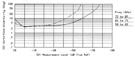
10 Measurement uncertainty Reflection measurements Magnitude Phase Magnitude Phase Transmission measurements Magnitude Phase Magnitude Phase Figure 12 10
11 Agilent 8510XF system performance Agilent E7350A Option 005 (45 MHz to 110 GHz) The following specifications describe the system performance of the 8510XF system in the E7350A Option 005 configuration, from GHz to 110 GHz. The following system configuration was used to generate the specifications: Test set: Millimeter controller and two test heads, 45 MHz to 110 GHz RF sources: Agilent 83621B and 83651B synthesized sweepers (one each) Calibration kit: Agilent 85059A 1.0 mm precision calibration/verification kit Calibration techniques: SOLT to 50 GHz, and offset-shorts from 50 to 110 GHz Dynamic range (for transmission measurements) Frequency range (GHz) to 2 2 to to to to to to to 110 Maximum power (in) measured at port 2 0 dbm 0 dbm +10 dbm +10 dbm 0 dbm 0 dbm 0 dbm 0 dbm Reference power (out) at port 1 (nominal) 0 dbm 0 dbm 12 dbm 12 dbm 7 dbm 12 dbm 12 dbm 12 dbm Minimum power (in) measured at port 2 74 dbm 104 dbm 84 dbm 84 dbm 75 dbm 70 dbm 70 dbm 70 dbm Receiver dynamic range 74 db 104 db 94 db 94 db 75 db 70 db 70 db 70 db System dynamic range 1 74 db 104 db 72 db 72 db 68 db 58 db 58 db 58 db Measurement port characteristics Frequency range (GHz) RESIDUAL to 2 2 to to to to to to to 110 Directivity 30 db 30 db 26 db 24 db 28 db 28 db 26 db 26 db Source match 27 db 27 db 23 db 21 db 28 db 28 db 26 db 26 db Load match 27 db 27 db 23 db 21 db 28 db 28 db 26 db 26 db Reflection tracking ±0.10 db ±0.10 db ±0.20 db ±0.25 db ±0.30 db ±0.30 db ±0.30 db ±0.30 db Transmission tracking ±0.273 db ±0.273 db ±0.429 db ±0.669 db ±0.322 db ±0.360 db ±0.451 db ±0.451 db Frequency range (GHz) RAW (Typical) to 2 2 to to to to to to to 110 Directivity 20 db 20 db 15 db 15 db 11 db 11 db 11 db 8 db Source match 20 db 20 db 15 db 15 db 11 db 11 db 11 db 10 db Load match 11 db 11 db 10 db 10 db 10 db 10 db 9 db 9 db 1. System dynamic range = Pref Pmin, where Pref is the nominal or reference power out of port 1 with maximum power delivered from the source and Pmin is the minimum power into port 2 that can be measured above the peaks of the system s noise floor (10 db above the average noise floor). Noise floor is measured with full two-port error correction and 1024 averages. System dynamic range is the amount of attenuation that can be measured from a 0 db reference. 11


12 Measurement uncertainty Reflection measurements Magnitude Phase Magnitude Phase Transmission measurements Magnitude Phase Magnitude Figure 12 Phase 12


13 Cascade Microtech, Inc. Probing equipment from Cascade Microtech, Inc. The Cascade Microtech product line includes millimeter-wave probes, probe stations, autoprobers, calibration standards, measurement software and application support for all Agilent Technologies vector network analyzers. Combining Cascade Microtech probe products with Agilent analyzers provides all the tools needed for complete RF probing solutions through 110 GHz. A complete on-wafer, S-parameter test system configured for 45 MHz to 110 GHz consists of the new 8510XF coupled directly with wafer probe positioners on a Cascade Microtech prober. Wafer probes and calibration standards to match the test devices specified by the customer round out the equipment accessories. Customerselected calibration kits or software complete the requirements for accurately corrected S-parameter measurements. Positioners For on-wafer measurements, speciallydesigned X-Y-Z positioners conveniently hold the 8510XF test heads, the 11500J minimum-length cables, and the ACP110 wafer probes, providing micron motion control without measurement-degrading cable strain and losses. Mounting the test heads onto the X-Y-Z positioners allows for 1-micron placement accuracy, and completely eliminates errors caused by cable flexure. This solution provides better than 60 db connection repeatability up to 110 GHz. For coaxial measurements, module test stations (MTS) are available to use with the 8510XF system. Depending on your measurement needs, the MTS-1000 series can be configured with either one or both X-Y-Z positioners (a positioner is shown above). Each positioner has a X or Y movement of ±6 inches. Cascade Microtech probing systems A full range of Cascade RF probers is offered to fit all customer needs. All RF probers are designed specifically for thin wafer usage with easy loading stages, and offer patented auxiliary chucks that handle the calibration standards. Probers are classified as manual, semi-automatic, and fully automatic. A manual probe station requires the operator to make all position adjustments manually, using a microscope to watch the position of the probe tips. Semi-automatic probe stations can be programmed with a wafer map, so that the system automatically locates and measures every device on the wafer. (Or, in indexing mode, the system measures the first device, and waits for the operator to push a button before it proceeds to the next device.) a Figure 14. (a) 8510XF test heads; (b) ACP110 wafer probes; (c) 11500J cables; (d) specially designed X-Y-Z positioners to conveniently hold the 8510XF test heads b c a d Fully automatic probe stations are able to load a series of wafers from a cassette, automatically measuring each DUT on each wafer (using a wafer map) before replacing the wafer in the cassette. In automatic and semi-automatic probe stations, the adjustments in the X, Y, and Z axes are used to put the test probes into the proper positions relative to one another; the chuck then moves the wafer so that the probe tips are brought into contact with each device to be tested. 13
14 Cascade RF probers 8510XF East West WinCal Model Style application ACP110-L ACP110-C positioner positioner software Summit 9101 Manual General purpose VNACAL-WIN-M Summit Semi-auto Modeling VNACAL-WIN Summit Manual General purpose VNACAL-WIN-M Summit Manual GP thermal VNACAL-WIN Summit Semi-auto Characterization VNACAL-WIN Summit Semi-auto Thermal modeling VNACAL-WIN PS21 RF Automatic Production SQ SQ SP-VNACAL-WIN-01 For general characterization work, choose the Summit The Summit 9101 chuck is designed to hold a wide range of wafer sizes, from single dies as small as 500 microns to 150-mm wafers. Fine-pitch lead screws allow for a manual placement repeatability under 5 microns on a test device. For metrology-grade semi-automated RF measurements, choose the Summit Full wafers can be autoprobed with 1-micron repeatability. Fully automatic VNA calibrations repeat to under 0.03 vector magnitude, assuring data integrity. For extensive temperature-dependent characterization, choose the Summit The Summit 12651, with patented MicroChamber, yields fast, frost-free measurements from 65 C to +200 C in a light- and EMI/RFItight enclosure. For exhaustive characterization, process monitoring or production device testing, choose the PS21 RF Autoprober. The PS21 offers 75 mm to 200 mm wafer cassette handling, Micro- Chambers with double-wall EMI/RFI shielding, and a full range of built-in temperature options from 55 C to +200 C. Wafer probes and calibration standards The ACP110 series wafer probes offers Ground-Signal-Ground (GSG) standard tips with pitches ranging from 50 microns to 150 microns to cover all specific test needs. The ACP110-L, with insertion loss <1.0 db, is designed specifically for S-parameter, noise parameter and load pull disciplines while the ACP110-C is used for thermal characterization from 65 C to +200 C. Cascade offers two mode-free impedance standard substrates (ISSs) for full 2-port ACP110 calibration support. Each ISS offers multiple sets of standards, verified to compare favorably with the rigorous NIST multi-line TRL calibration methodology. Calibration reproducibility between ISSs is better than 50 db due to the uniformity of thin film standards. W- band ISS part number covers ACP110 with 75-micron to 150- micron pitches, while the part number ISS is used for 50-micron pitch probes. The companion diskette (part number ) provides downloadable 8510 cal kits supporting SOLT, LRM and TRL calibrations. Computer-aided calibration and system support Cascade s WinCal PC software utilities enhance your 8510XF on-wafer system performance. WinCal provides tools that can automatically monitor total system drift and check the performance of each probe. Linked to the Summit or PS21 RF, WinCal provides fully automatic calibrations shown to repeat better than 56 db using the NIST VERIFY program extremely useful for over-temperature S-parameters. Cascade prober upgrade paths Numerous upgrades are available to enhance your existing Cascade RF prober investments. Depending on your current measurement setup, you may need a standard, preconfigured upgrade or a customized upgrade. Please consult with a Cascade Microtech factory representative for customized system solutions. For more information contact: Cascade Microtech, Inc NW 206th Ave Beaverton, OR (503)
15 Ordering Information Agilent 8510XF family single-connection, single-sweep systems Complete measurement systems E7340A complete measurement system, 2 to 85 GHz E7350A complete measurement system, 2 to 110 GHz The following options are available for both systems: Option 005 add 45 MHz to 2 GHz low frequency extension Option 006 add RF pass thru (provides coupled output of 50 GHz source)1 Option 010 add time domain Option /240V line voltage operation Option W31 add two years additional on-site service Each complete rack-mounted system consists of the following: 8510C network analyzer Millimeter-wave subsystem (85 GHz or 110 GHz) 83621B synthesizer 83651B synthesizer System rack (Calibration/verification kit and 1.0 mm test port cables are not included and must be ordered separately.) Factory integration of the 8510XF system integrates all the main system instruments in the system cabinet and fully tests the system. On-site installation is included, and the entire system carries a full one-year, on-site warranty. For on-wafer applications, Cascade Microtech provides complete probing systems using the 8510XF. These include both new probing systems and upgrades to existing Cascade Microtech products. Cascade can also provide on-wafer verification and probing system training. Once the 8510XF system is verified in coax, Cascade Microtech will verify the system through its wafer probes. 1.0 mm accessories The following accessories are available for use with the 8510XF system, but are not included in the system I 1.0 mm (f-f) test port cable (8.8 cm) 11500J 1.0 mm (m-f) test port cable (16.0 cm) K 1.0 mm (m-f) test port cable (20.0 cm) L 1.0 mm (m-f) test port cable (24.0 cm) A DC to 110 GHz precision calibration/verification kit V281C 1.0 mm (f) to V-band waveguide adapter V281D 1.0 mm (m) to V-band waveguide adapter W281C 1.0 mm (f) to W-band waveguide adapter W281D 1.0 mm (m) to W-band waveguide adapter 11920A 1.0 mm (m) to 1.0 mm (m) adapter 11920B 1.0 mm (f) to 1.0 mm (f) adapter 11920C 1.0 mm (m) to 1.0 mm (f) adapter 11921A 1.0 mm (m) to 1.85 mm (m) adapter 11921B 1.0 mm (f) to 1.85 mm (f) adapter 11921C 1.0 mm (m) to 1.85 mm (f) adapter 11921D 1.0 mm (f) to 1.85 mm (m) adapter 11922A 1.0 mm (m) to 2.4 mm (m) adapter 11922B 1.0 mm (f) to 2.4 mm (f) adapter 11922C 1.0 mm (m) to 2.4 mm (f) adapter 11922D 1.0 mm (f) to 2.4 mm (m) adapter 11923A 1.0 mm (f) connector launch assembly 1. Option 006 is needed for multiple test sets configuration. Additional test set(s) must have Option 001 installed. See Agilent 8510 Multiple Test Sets, product note, (literature number E) for additional information. 2. For on-wafer applications, two 11500J/K/L cables are required. One cable for each test port. 15
16 System upgrades Upgrades available for existing 8510 systems to 8510XF single-sweep systems Upgrades from 85107B 85109C 85106C 85106C w/option D 85106C w/ Option 001 and D w/ Option C w/ Option 002 to 85 GHz E7345A E7346A E7347A to 110 GHz E7355A E7356A E7357A 8510C Millimeter subsystem 83651B 83621B Customer owned equipment Upgrades for 85107B 85109C Upgrade consists of two test heads, a millimeter test set controller, an 83621B for LO source, and rack. It does not include calibration kits or test port cables. E7345A upgrade to an 8510XF 85 GHz system E7355A upgrade to an 8510XF 110 GHz system The following options are available for both upgrades: Option 005 add 45 MHz to 2 GHz low frequency extension Option 006 add RF pass thru (provides coupled output of 50 GHz source for additional test sets. Additional test set(s) must have Option 001 installed.) Upgrades for 85106C 85106C with Option 002 (replaced 8350B/83540A with 83621A/B) 85106D Upgrade consists of two test heads, a millimeter test set controller and an 83651B for RF source. It does not include calibration kits, test port cables or rack. E7346A upgrade to an 8510XF 85 GHz system E7356A upgrade to an 8510XF 110 GHz system The following options are available for both upgrades: Option 005 add 45 MHz to 2 GHz low frequency extension Option 006 add RF pass thru (provides coupled output of 50 GHz source for additional test sets. Additional test set(s) must have Option 001 installed.) 16
17 Upgrades for 85106C with Options 001 and 002 (added 8517B, replaced 83621A/B with 83651A/B, and replaced 8350B/83540A with 83621A/B) 85106D with Option 001 (added 8517B and replaced 83621B with 83651B) 85109C with Option 002 (replaced 8350B/83540A with 83621A/B) Upgrade consists of two test heads and a millimeter test set. It does not include calibration kits, test port cables or rack. E7347A upgrade to an 8510XF 85 GHz system E7357A upgrade to an 8510XF 110 GHz system The following options are available for both upgrades: Option 005 add 45 MHz to 2 GHz low frequency extension Option 006 add RF pass thru (provides coupled output of 50 GHz source for additional test sets. Additional test set(s) must have Option 001 installed.) Related literature Pub. number Agilent 8510C Family Network Analyzer, Configuration Guide E Agilent 8510C Family Network Analyzer, Data Specifications E Agilent 8510 System Solutions, Color Brochure E Agilent 8510 Multiple Test Sets, Product Note E Agilent 11923A 1.0 mm Connector Launch, Product Overview E Agilent 11920/1/2 A, B, C, D Series 1.0 mm Coaxial Adapters, Product Overview E Agilent V/W 281C, D Series Waveguide-to-1.0 mm Coaxial Adapters, Product Overview E 17
18 Agilent Updates Get the latest information on the products and applications you select. Agilent Direct Quickly choose and use your test equipment solutions with confidence. Agilent Open Agilent Open simplifies the process of connecting and programming test systems to help engineers design, validate and manufacture electronic products. Agilent offers open connectivity for a broad range of system-ready instruments, open industry software, PC-standard I/O and global support, which are combined to more easily integrate test system development. Agilent Technologies Test and Measurement Support, Services, and Assistance Agilent Technologies aims to maximize the value you receive, while minimizing your risk and problems. We strive to ensure that you get the test and measurement capabilities you paid for and obtain the support you need. Our extensive support resources and services can help you choose the right Agilent products for your applications and apply them successfully. Every instrument and system we sell has a global warranty. Two concepts underlie Agilent s overall support policy: Our Promise and Your Advantage. Our Promise Our Promise means your Agilent test and measurement equipment will meet its advertised performance and functionality. When you are choosing new equipment, we will help you with product information, including realistic performance specifications and practical recommendations from experienced test engineers. When you receive your new Agilent equipment, we can help verify that it works properly and help with initial product operation. Your Advantage Your Advantage means that Agilent offers a wide range of additional expert test and measurement services, which you can purchase according to your unique technical and business needs. Solve problems efficiently and gain a competitive edge by contracting with us for calibration, extra-cost upgrades, out-of-warranty repairs, and onsite education and training, as well as design, system integration, project management, and other professional engineering services. Experienced Agilent engineers and technicians worldwide can help you maximize your productivity, optimize the return on investment of your Agilent instruments and systems, and obtain dependable measurement accuracy for the life of those products. For more information on Agilent Technologies products, applications or services, please contact your local Agilent office. The complete list is available at: Phone or Fax United States: (tel) (fax) Canada: (tel) (fax) China: (tel) (fax) Europe: (tel) Japan: (tel) (81) (fax) (81) Korea: (tel) (080) (fax) (080) Latin America: (tel) (305) Taiwan: (tel) (fax) Other Asia Pacific Countries: (tel) (65) (fax) (65) tm_ap@agilent.com Contacts revised: 09/26/05 Product specifications and descriptions in this document subject to change without notice. Agilent Technologies, Inc. 1999, 2000, 2006 Printed in USA, July 13, E
Agilent N9355/6 Power Limiters 0.01 to 18, 26.5 and 50 GHz
 Agilent N9355/6 Power Limiters 0.01 to 18, 26.5 and 50 GHz Technical Overview High Performance Power Limiters Broad frequency range up to 50 GHz maximizes the operating range of your instrument High power
Agilent 11713A Attenuator/Switch Driver
 Agilent A Attenuator/Switch Driver Configuration Guide This configuration guide will help you through the process of configuring a switching system utilizing Agilent s A attenuator/switch driver. The A
Agilent 87075C Multiport Test Set Product Overview
 Agilent 87075C Multiport Test Set Product Overview A complete 75 ohm system for cable TV device manufacturers Now, focus on testing, not reconnecting! For use with the Agilent 8711 C-Series of network
Artisan Technology Group is your source for quality new and certified-used/pre-owned equipment
 Artisan Technology Group is your source for quality new and certified-used/pre-owned equipment FAST SHIPPING AND DELIVERY TENS OF THOUSANDS OF IN-STOCK ITEMS EQUIPMENT DEMOS HUNDREDS OF MANUFACTURERS SUPPORTED
Agilent 87075C 75 Ohm Multiport Test Sets for use with Agilent E5061A ENA-L Network Analyzers
 Agilent 87075C 75 Ohm Multiport Test Sets for use with Agilent E5061A ENA-L Network Analyzers Technical Overview Focus on testing, not reconnecting! Maximize production throughput of cable-tv multiport
Agilent CSA Spectrum Analyzer N1996A
 Agilent CSA Spectrum Analyzer N1996A Demonstration Guide Introduction This step-by-step demo guide will help you explore the unprecedented value of the Agilent CSA spectrum analyzer for meeting your design,
Agilent 81600B Tunable Laser Source Family
 Agilent 81600B Tunable Laser Source Family Technical Specifications August 2007 The Agilent 81600B Tunable Laser Source Family offers the full wavelength range from 1260 nm to 1640 nm with the minimum
Agilent 86120B, 86120C, 86122A Multi-Wavelength Meters Technical Specifications
 Agilent 86120B, 86120C, 86122A Multi-Wavelength Meters Technical Specifications March 2006 Agilent multi-wavelength meters are Michelson interferometer-based instruments that measure wavelength and optical
Full-featured CW Microwave Counters for Field, Factory or Lab
 Full-featured CW Microwave Counters for Field, Factory or Lab Product Overview Agilent 53150A 20 GHz Counter Agilent 53151A 26.5 GHz Counter 46 GHz Counter High performance microwave counters: at home,
Agilent 81600B Tunable Laser Source Family Technical Specifications August New model: nm, low SSE output!
 New model: 1260 1375 nm, low SSE output! Agilent Tunable Laser Source Family Technical Specifications August 2004 The Agilent Tunable Laser Source Family offers the from 1260 nm to 1640 nm with the minimum
Agilent I 2 C Debugging
 546D Agilent I C Debugging Application Note1351 With embedded systems shrinking, I C (Inter-integrated Circuit) protocol is being utilized as the communication channel of choice because it only needs two
Broadcast Television Measurements
 Broadcast Television Measurements Data Sheet Broadcast Transmitter Testing with the Agilent 85724A and 8590E-Series Spectrum Analyzers RF and Video Measurements... at the Touch of a Button Installing,
MILLIMETER WAVE VNA MODULE BROCHURE
 MILLIMETER WAVE VNA MODULE BROCHURE General Information OML, founded in 1991, is an expert at millimeter wave (mm-wave) measurements. Our successful foundation is built on mm-wave S-parameter measurements,
Agilent E5500 Series Phase Noise Measurement Solutions Product Overview
 Agilent E5500 Series Phase Noise Measurement Solutions Product Overview E5501A/B E5502A/B E5503A/B E5504A/B 50 khz to 1.6 GHz 50 khz to 6 GHz 50 khz to 18 GHz 50 khz to 26.5 GHz The Agilent E5500 series
Agilent N7744A 4-Channel Optical Multiport Power Meter N7745A 8-Channel Optical Multiport Power Meter. Fully compliant to LXI Class C specification
 Agilent N7744A 4-Channel Optical Multiport Power Meter N7745A 8-Channel Optical Multiport Power Meter Fully compliant to LXI Class C specification General Information Up to 8 power meter channels in a
Agilent N5183A MXG Microwave Signal Generator
 Agilent N5183A MXG Microwave Signal Generator Configuration Guide This guide is designed to assist in the ordering process for the MXG microwave signal generator. Agilent MXG microwave signal generator
Agilent E5100A Network Analyzer
 Agilent E5100A Network Analyzer Data Sheet These specifications are the performance standards or limits against which the instrument is tested. When shipped from the factory, the E5100A meets the specifications
R&S ZVA-Zxx Millimeter-Wave Converters Specifications
 R&S ZVA-Zxx Millimeter-Wave Converters Specifications Data Sheet Version 19.00 CONTENTS Definitions... 3 General information... 4 Specifications... 5 Test port... 5 Source input (RF IN)... 5 Local oscillator
R-1580A Microwave Downconverter. Product Brochure
 R-1580A Microwave Downconverter Product Brochure Jan 2018 Highlights The DSII Model R-1580A Microwave Downconverter extends the coverage of the R-1550A, or other DSII wide range receivers, to 22 GHz. The
Agilent 83437A Broadband Light Source Agilent 83438A Erbium ASE Source
 Agilent 83437A Agilent 83438A Erbium ASE Source Product Overview H Incoherent light sources for single-mode component and sub-system characterization The Technology 2 The Agilent Technologies 83437A (BBLS)
MPI Cable Selection Guide
 MPI Cable Selection Guide MPI engineers focus to provide on optimal cable solutions taking into account a number of requirements specific for wafer-level measurement systems: optimal cable length, cable
Agilent Series Preselected Millimeter Mixers
 Agilent 11974 Series Preselected Millimeter Mixers RF Sections Available in Four Bands from 26.5 to 75 GHz Data Sheet For the first time, preselected signal analysis is available to 75 GHz. With preselection,
Agilent Agilent 86120B, 86120C, 86122A Multi-Wavelength Meters Data Sheet
 Agilent Agilent 86120B, 86120C, 86122A Multi-Wavelength Meters Data Sheet Agilent multi-wavelength meters are Michelson interferometer-based instruments that measure wavelength and optical power of laser
Agilent 4-Port PNA-L Microwave Network Analyzer
 Agilent 4-Port PNA-L Microwave Network Analyzer N523A 3 khz to 13.5, 2 GHz Data Sheet Note: Specification information in this document is also available within the PNA-L network analyzer s internal Help
ENGINEERING COMMITTEE Interface Practices Subcommittee AMERICAN NATIONAL STANDARD ANSI/SCTE
 ENGINEERING COMMITTEE Interface Practices Subcommittee AMERICAN NATIONAL STANDARD ANSI/SCTE 48-3 2011 Test Procedure for Measuring Shielding Effectiveness of Braided Coaxial Drop Cable Using the GTEM Cell
Microwave Counter, Power Meter and DVM in One Portable Package
 Agilent 53140 Series Microwave Counter, Power Meter and DVM in One Portable Package Product Overview Everything you need for the installation and maintenance of microwave links: A choice of frequency counter
R&S ZN-Z32/-Z33 Automatic In-line Calibration Modules Ensuring high accuracy with thermal vacuum testing and multiport measurements
 R&S ZN-Z32/-Z33 Automatic In-line Calibration Modules Ensuring high accuracy with thermal vacuum testing and multiport measurements Product Brochure Version 01.01 R&S ZN-Z32/-Z33 Automatic In-Line Calibration
Zen and the Art of On-Wafer Probing A Personal Perspective
 Zen and the Art of On-Wafer Probing A Personal Perspective Rob Sloan School E&EE, University of Manchester - after Robert Pirsig Device or Circuit Measurement at Microwave/ Millimetre-wave/ THz frequencies
Agilent Migration from 8712/8714 Series to ENA-L Network Analyzers
 Agilent Migration from 8712/8714 Series to ENA-L Network Analyzers Technical Overview The Standard Just Got Better! Enhanced usability and performance Affordably priced Minimal software migration A new
Debugging Digital Cameras: Detecting Redundant Pixels
 Debugging Digital Cameras: Detecting Redundant Pixels Application Note Introduction Pixel problems and bit problems associated with their hardware and firmware designs can seriously challenge the designers
30 GHz Attenuator Performance and De-Embedment
 30GHz De-Embedment Application Note - Page 1 of 6 Theory of De-Embedment. Due to the need for smaller packages and higher signal integrity a vast majority of todays RF and Microwave components are utilizing
Agilent MSO and CEBus PL Communications Testing Application Note 1352
 546D Agilent MSO and CEBus PL Communications Testing Application Note 135 Introduction The Application Zooming In on the Signals Conclusion Agilent Sales Office Listing Introduction The P300 encapsulates
Features. = +25 C, IF = 1 GHz, LO = +13 dbm*
 v.5 HMC56LM3 SMT MIXER, 24-4 GHz Typical Applications Features The HMC56LM3 is ideal for: Test Equipment & Sensors Point-to-Point Radios Point-to-Multi-Point Radios Military & Space Functional Diagram
JD725A Cable and Antenna Analyzer - Dual Port
 COMMUNICATIONS TEST & MEASUREMENT SOLUTIONS JD725A Cable and Antenna Analyzer - Dual Port Key Features Portable and lightweight handheld instrument Built-in wireless frequency bands as well as the most
R&S ZVA-Zxx Millimeter-Wave Converters Specifications
 ZVA-Zxx_dat-sw_en_5214.2033.22_umschlag.indd 1 Data Sheet 13.00 Test & Measurement R&S ZVA-Zxx Millimeter-Wave Converters Specifications 28.01.2013 15:08:06 CONTENTS General information... 3 Definitions...
Keysight Technologies De-Embedding and Embedding S-Parameter Networks Using a Vector Network Analyzer. Application Note
 Keysight Technologies De-Embedding and Embedding S-Parameter Networks Using a Vector Network Analyzer Application Note L C Introduction Traditionally RF and microwave components have been designed in packages
USB-TG124A Tracking Generator User Manual
 USB-TG124A Tracking Generator User Manual Signal Hound USB-TG124A User Manual 2017, Signal Hound, Inc. 35707 NE 86th Ave La Center, WA 98629 USA Phone 360.263.5006 Fax 360.263.5007 This information is
R&S ZVA110 Vector Network Analyzer Specifications
 ZVA110_dat-sw_en_5214-4813-22_cover.indd 1 Data Sheet 04.00 Test & Measurement R&S ZVA110 Vector Network Analyzer Specifications 15.11.2013 14:42:28 CONTENTS Definitions... 3 Specifications... 4 Overview...
Basic Verification of Power Loadpull Systems
 MAURY MICROWAVE 1 Oct 2004 C O R P O R A T I O N Basic Verification of Power Loadpull Systems Author: John Sevic, MSEE Automated Tuner System Technical Manager, Maury Microwave Corporation What is Loadpull
Agilent E4430B 1 GHz, E4431B 2 GHz, E4432B 3 GHz, E4433B 4 GHz Measuring Bit Error Rate Using the ESG-D Series RF Signal Generators, Option UN7
 Agilent E4430B 1 GHz, E4431B 2 GHz, E4432B 3 GHz, E4433B 4 GHz Measuring Bit Error Rate Using the ESG-D Series RF Signal Generators, Option UN7 Product Note Introduction Bit-error-rate analysis As digital
Precision TNC Coaxial Calibration Kit
 User Guide Precision TNC Coaxial Calibration Kit DC to 18 GHz Models: 8650CK10/11 8650CK20/21 8650-511 (A) 2/15 User Guide Precision TNC Coaxial Calibration Kit DC to 18 GHz Models: 8650CK10/11 8650CK20/21
Monoblock RF Filter Testing SMA, In-Fixture Calibration and the UDCK
 Application Note AN1008 Introduction Monoblock RF Filter Testing SMA, In-Fixture Calibration and the UDCK Factory testing needs to be accurate and quick. While the most accurate (and universally available)
Agilent 87405C 100 MHz to 18 GHz Preamplifier
 Agilent 8745C 1 MHz to 18 GHz Preamplifier Technical Overview Key Features Rugged, portable design for ease of use in the field Probe-power bias connection eliminates the need for an additional power supply
Analog Devices Welcomes Hittite Microwave Corporation NO CONTENT ON THE ATTACHED DOCUMENT HAS CHANGED
 Analog Devices Welcomes Hittite Microwave Corporation NO CONTENT ON THE ATTACHED DOCUMENT HAS CHANGED www.analog.com www.hittite.com THIS PAGE INTENTIONALLY LEFT BLANK v1.55 Typical Applications The is
Agilent Understanding the Agilent 34405A DMM Operation Application Note
 Agilent Understanding the Agilent 34405A DMM Operation Application Note Introduction Digital multimeter (DMM) is a basic device in the electrical world and its functions are usually not fully utilized.
Keysight Technologies High-Power Measurements Using the E5072A ENA Series Network Analyzer. Application Note
 Keysight Technologies High-Power Measurements Using the E5072A ENA Series Network Analyzer Application Note Table of Contents Coniguration 1 Standard 2-port coniguration... 3 Coniguration 2 Measurements
Practical De-embedding for Gigabit fixture. Ben Chia Senior Signal Integrity Consultant 5/17/2011
 Practical De-embedding for Gigabit fixture Ben Chia Senior Signal Integrity Consultant 5/17/2011 Topics Why De-Embedding/Embedding? De-embedding in Time Domain De-embedding in Frequency Domain De-embedding
Vector Network Analyzer TTR503A/TTR506A USB Vector Network Analyzer Preliminary Datasheet. Subject to change.
 Vector Network Analyzer TTR503A/TTR506A USB Vector Network Analyzer Preliminary Datasheet. Subject to change. Applications Academic/Education Design, development and manufacturing of passive and active
Parameter Symbol Units MIN MAX. RF Input power (CW) Pin dbm +23
 Pin dbm +23") AMT-L0014 100MHz to 2500MHz High Linearity Limiter for A/D Converters Data Sheet Features Ideal protection for A/D converters with high dynamic range Flat Insertion Loss < 1.7 db from 300 to 2000MHz Frequency
AMT-L0014 100MHz to 2500MHz High Linearity Limiter for A/D Converters Data Sheet Features Ideal protection for A/D converters with high dynamic range Flat Insertion Loss < 1.7 db from 300 to 2000MHz Frequency
PM Series Microwave Power Calibration System
 PM Series Microwave Power Calibration System Supports Sensors from most major manufactures up to 50 GHz Faster than direct compare method Lowest total uncertainty National Metrology Institute class thermistor
Virtual Thru-Reflect-Line (TRL) Calibration
 Calibration") Virtual Thru-Reflect-Line (TRL) By John E. Penn Introduction In measuring circuits at microwave frequencies, it is essential to have a known reference plane, particularly when measuring transistors whose
Virtual Thru-Reflect-Line (TRL) By John E. Penn Introduction In measuring circuits at microwave frequencies, it is essential to have a known reference plane, particularly when measuring transistors whose
PM Series Microwave Power Calibration System
 PM Series Microwave Power Calibration System Supports Sensors from most major manufacturers from 6 khz to 50 GHz Faster than direct compare method Lowest total uncertainty National Metrology Institute
specifications 8510C Network Analyzer 45 MHz to 110 GHz
 specifications 8510C Network Analyzer 45 MHz to 110 GHz Contents Page System performance characteristics.........3 Major HP 8510 Network Analyzer Systems HP 8510E, Option 005, 45 MHz to 20 GHz...........4
De-embedding Techniques For Passive Components Implemented on a 0.25 µm Digital CMOS Process
 PIERS ONLINE, VOL. 3, NO. 2, 27 184 De-embedding Techniques For Passive Components Implemented on a.25 µm Digital CMOS Process Marc D. Rosales, Honee Lyn Tan, Louis P. Alarcon, and Delfin Jay Sabido IX
Keysight Technologies Antenna Test. Selection Guide
 Keysight Technologies Antenna Test Selection Guide 1. Introduction Keysight Technologies, Inc. provides many of the components you need to make accurate antenna and radar cross-section (RCS) measurements.
Agilent PN Time-Capture Capabilities of the Agilent Series Vector Signal Analyzers Product Note
 Agilent PN 89400-10 Time-Capture Capabilities of the Agilent 89400 Series Vector Signal Analyzers Product Note Figure 1. Simplified block diagram showing basic signal flow in the Agilent 89400 Series VSAs
Critical Benefits of Cooled DFB Lasers for RF over Fiber Optics Transmission Provided by OPTICAL ZONU CORPORATION
 Critical Benefits of Cooled DFB Lasers for RF over Fiber Optics Transmission Provided by OPTICAL ZONU CORPORATION Cooled DFB Lasers in RF over Fiber Optics Applications BENEFITS SUMMARY Practical 10 db
Agilent E4416A/E4417A EPM-P Series Power Meters and E-Series E9320 Peak and Average Power Sensors
 View at www.testequipmentdepot.com Agilent E4416A/E4417A EPM-P Series Power Meters and E-Series E9320 Peak and Average Power Sensors Data Sheet Test Equipment Depot - 800.517.8431-99 Washington Street
ENGINEERING COMMITTEE Interface Practices Subcommittee AMERICAN NATIONAL STANDARD ANSI/SCTE Mainline Pin (plug) Connector Return Loss
 Connector Return Loss") ENGINEERING COMMITTEE Interface Practices Subcommittee AMERICAN NATIONAL STANDARD ANSI/SCTE 125 2007 Mainline Pin (plug) Connector Return Loss NOTICE The Society of Cable Telecommunications Engineers (SCTE)
ENGINEERING COMMITTEE Interface Practices Subcommittee AMERICAN NATIONAL STANDARD ANSI/SCTE 125 2007 Mainline Pin (plug) Connector Return Loss NOTICE The Society of Cable Telecommunications Engineers (SCTE)
R&S HA-Z24E External Preamplifier 1 GHz to 85 GHz Specifications
 R&S HA-Z24E External Preamplifier 1 GHz to 85 GHz Specifications Data Sheet Version 01.01 Definitions General Product data applies under the following conditions: Three hours storage at ambient temperature
Transcom Instruments. Product Brochure TRANSCOM INSTRUMENTS. Product Brochure. 1
 TRANSCOM INSTRUMENTS Product Brochure Transcom Instruments Product Brochure www.transcomwireless.com 1 T5000 Series Bench-top Vector Network Analyzer Overview T5000 Series Bench-top Vector Network Analyzer
SR1320AD DC TO 20GHZ GAAS SP3T SWITCH
 FEATURES: Low Insertion Loss: 1.6dB at 20GHz High Isolation: 42dB at 20GHz Excellent Return Loss 19ns Switching Speed GaAs phemt Technology PACKAGE - BARE DIE, 1.91MM X 2.11MM X 0.10MM 100% RoHS Compliant
INTEGRATED ASSEMBLIES MICROWAVE SOLUTIONS FROM TELEDYNE COUGAR
 INTEGRATED ASSEMBLIES MICROWAVE SOLUTIONS FROM TELEDYNE COUGAR INTEGRATED ASSEMBLIES MICROWAVE SOLUTIONS FROM TELEDYNE COUGAR Teledyne Cougar offers full first-level integration capabilities, providing
Parameter Symbol Units MIN MAX. RF Input Power (CW) Pin dbm +20. LO Input Power (CW) Pin dbm +27
 Pin dbm +20. LO Input Power (CW) Pin dbm +27") AMT-X0103 6 GHz to 10 GHz RF/LO IMAGE REJECT MIXER Data Sheet Features RF/LO Frequency Range 6 to 10 GHz Image Rejection 30 db Typical Typical Conversion loss 6 db LO-RF Isolation 36 db LO-IF Isolation
AMT-X0103 6 GHz to 10 GHz RF/LO IMAGE REJECT MIXER Data Sheet Features RF/LO Frequency Range 6 to 10 GHz Image Rejection 30 db Typical Typical Conversion loss 6 db LO-RF Isolation 36 db LO-IF Isolation
Exceptional performance
 Established 1981 Advanced Test Equipment Rentals www.atecorp.com 800-404-ATEC (2832) Agilent 11970 Series Harmonic Mixers Data Sheet 18 to 110 GHz 11970K*, 11970A, 11970Q, 11970U, 11970V, 11970W For use
Advanced Test Equipment Rentals ATEC (2832)
") E stablished 1981 Advanced Test Equipment Rentals www.atecorp.com 800-404-ATEC (2832) Technical Datasheet Scalar Network Analyzer Model 8003-10 MHz to 40 GHz The Giga-tronics Model 8003 Precision Scalar
E stablished 1981 Advanced Test Equipment Rentals www.atecorp.com 800-404-ATEC (2832) Technical Datasheet Scalar Network Analyzer Model 8003-10 MHz to 40 GHz The Giga-tronics Model 8003 Precision Scalar
Tutorial Session 8:00 am Feb. 2, Robert Schaefer, Agilent Technologies Feb. 2, 2009
 Tutorial Session 8:00 am Feb. 2, 2009 Robert Schaefer, Agilent Technologies Feb. 2, 2009 Objectives Present Advanced Calibration Techniques Summarize Existing Techniques Present New Advanced Calibration
Calibrating attenuators using the 9640A RF Reference
 Calibrating attenuators using the 9640A RF Reference Application Note The precision, continuously variable attenuator within the 9640A can be used as a reference in the calibration of other attenuators,
Measurement Accuracy of the ZVK Vector Network Analyzer
 Product: ZVK Measurement Accuracy of the ZVK Vector Network Analyzer Measurement deviations due to systematic errors of a network analysis system can be drastically reduced by an appropriate system error
Switching Solutions for Multi-Channel High Speed Serial Port Testing
 Switching Solutions for Multi-Channel High Speed Serial Port Testing Application Note by Robert Waldeck VP Business Development, ASCOR Switching The instruments used in High Speed Serial Port testing are
Analyze Frequency Response (Bode Plots) with R&S Oscilloscopes Application Note
 with R&S Oscilloscopes Application Note") Analyze Frequency Response (Bode Plots) with R&S Oscilloscopes Application Note Products: R&S RTO2002 R&S RTO2004 R&S RTO2012 R&S RTO2014 R&S RTO2022 R&S RTO2024 R&S RTO2044 R&S RTO2064 This application
Analyze Frequency Response (Bode Plots) with R&S Oscilloscopes Application Note Products: R&S RTO2002 R&S RTO2004 R&S RTO2012 R&S RTO2014 R&S RTO2022 R&S RTO2024 R&S RTO2044 R&S RTO2064 This application
SCSI Cable Characterization Methodology and Systems from GigaTest Labs
 lide - 1 CI Cable Characterization Methodology and ystems from GigaTest Labs 134. Wolfe Rd unnyvale, CA 94086 408-524-2700 www.gigatest.com lide - 2 Overview Methodology summary Fixturing Instrumentation
We bring quality to light. SNT 10 DC Power Supply
 We bring quality to light. SNT 10 DC Power Supply State-of-the-art choice for a reliable, high power DC supply The SNT 10 DC Power Supply is a precision tool developed to meet the needs of the automotive
Agilent E4887A HDMI TMDS Signal Generator Platform
 Agilent E4887A HDMI TMDS Signal Generator Platform Data Sheet Version 1.9 Preliminary E4887A- 007 E4887A- 037 E4887A- 003 Page Convenient Compliance Testing and Characterization of HDMI 1.3 Devices The
Application Note DT-AN-2115B-1. DTA-2115B Verification of Specifations
 DTA-2115B Verification of Specifations APPLICATION NOTE January 2018 Table of Contents 1. Introduction... 3 General Description of the DTA-2115B... 3 Purpose of this Application Note... 3 2. Measurements...
GaAs MMIC Double Balanced Mixer
 Page 1 The is a passive GaAs double balanced MMIC mixer suitable for both up and down-conversion applications. As with all Marki Microwave mixers, it features excellent conversion loss, isolation and spurious
MAX2660/MAX2661/MAX2663/MAX2671 Evaluation Kits
 9-382; Rev ; 9/99 MAX2660/MAX266/MAX2663/MAX267 General Description The MAX2660/MAX266/MAX2663/MAX267 evaluation kits simplify evaluation of the MAX2660/MAX266/ MAX2663/MAX267 upconverter s. They enable
Single-Output 2000 W
 Single-Output 2000 W 6571A-6575A Front panel and analog control of output voltage and current Fast, low-noise outputs Fan-speed control to minimize acoustic noise Protection features to ensure DUT safety
Limitations of a Load Pull System
 Limitations of a Load Pull System General Rule: The Critical Sections in a Load Pull measurement setup are the sections between the RF Probe of the tuners and the DUT. The Reflection and Insertion Loss
Why Engineers Ignore Cable Loss
 Why Engineers Ignore Cable Loss By Brig Asay, Agilent Technologies Companies spend large amounts of money on test and measurement equipment. One of the largest purchases for high speed designers is a real
Agilent 83000A Series Microwave System Amplifiers
 Agilent 83000A Series Microwave System Amplifiers Product Overview Agilent Technologies Microwave System Amplifiers 83006A 10 MHz to 26.5 GHz 83017A 500 MHz to 26.5 GHz 83018A 2 to 26.5 GHz 83020A 2 to
Satellite Up- and Downconverter Indoor / Outdoor
 Visit us at www.work-microwave.de Satellite Up- and Downconverter Indoor / Outdoor Single / Dual / Triple Band Single / Dual Channel S-, C-, X-, Ku-, K (DBS)-, Ka-, and Q-band WORK Microwave s satellite
A Simple, Yet Powerful Method to Characterize Differential Interconnects
 A Simple, Yet Powerful Method to Characterize Differential Interconnects Overview Measurements in perspective The automatic fixture removal (AFR) technique for symmetric fixtures Automatic Fixture Removal
GaAs MMIC Double Balanced Mixer
 Page 1 The is a highly linear passive GaAs double balanced MMIC mixer suitable for both up and down-conversion applications. As with all Marki Microwave mixers, it features excellent conversion loss, isolation
R&S RT-ZM Modular Probe System
 RT-ZMxx_fly_3607-5690-32_v0102.indd 3 roduct Flyer 01.02 3607.5690.32 01.02 D 1 en Test & Measurement R&S RT-ZM Modular robe System 08.11.2016 16:20:21 Addressing high-speed probing challenges Serv The
Product Brochure Version HZ-15_16_17_bro_en_ _v0100.indd 1
 Product Brochure Version 1. R&S HZ-15/R&S HZ-17 Probe Sets R&S HZ-16 Preamplifier E and H near-field emission measurements with test receivers, spectrum analyzers and oscilloscopes HZ-15_16_17_bro_en_5213-6687-12_v1.indd
R&S ZN-Z85 Switch Matrix Specifications
 R&S ZN-Z85 Switch Matrix Specifications Data Sheet Version 01.02 CONTENTS Definitions... 3 Block diagrams... 4 Specifications... 5 General features... 5 Performance data... 5 Remote control... 5 Switching
N5264A. New. PNA-X Measurement Receiver. Jim Puri Applications Specialist March Rev. Jan Page 1
 New N5264A PNA-X Measurement Receiver Jim Puri Applications Specialist March 2009 Page 1 Rev. 1 N5264A Measurement Receiver No connectors on front panel Page 2 Rev. 2 N5264A PNA-X Measurement Receiver
Keysight N9355/6 Power Limiters 0.01 to 18, 26.5 and 50 GHz High Performance Power Limiters. Technical Overview
 Keysight N9355/6 Power Limiters 0.01 to 18, 26.5 and 50 GHz High Performance Power Limiters Technical Overview Introduction Broad frequency range up to 50 GHz maximizes the operating range of your instrument
GaAs MMIC Triple Balanced Mixer
 Page 1 The is a passive MMIC triple balanced mixer. It features a broadband IF port that spans from 2 to 20 GHz, and has excellent spurious suppression. GaAs MMIC technology improves upon the previous
MTS/T-BERD 8000 Platform Optical Spectrum Analyzer Modules
 COMMUNICATIONS TEST & MEASUREMENT SOLUTIONS MTS/T-BERD 8000 Platform Optical Spectrum Analyzer Modules MTS/T-BERD platform Applications Provisioning and maintenance of ROADM networks Commissioning of DWDM
Agilent Series Harmonic Mixers
 Agilent 11970 Series Harmonic Mixers Data Sheet 18 to 110 GHz 11970K*, 11970A, 11970Q, 11970U, 11970V, 11970W For use with the Agilent E4407B, 8560E/EC Series, 8566B, 71000 Series, and PSA Series spectrum
RF Characterization Report
 HDBNC Series RF Connector HDBNC-J-P-GN-ST-EM1 HDBNC-J-P-GN-ST-BH1 HDBNC-J-P-GN-ST-TH1 Description: 75 Ohm True 75 TM High Density BNC Straight Jack, Edge Mount or Through-hole Samtec Inc. WWW.SAMTEC.COM
RF Characterization Report
 BNC7T-J-P-xx-ST-EMI BNC7T-J-P-xx-RD-BH1 BNC7T-J-P-xx-ST-TH1 BNC7T-J-P-xx-ST-TH2D BNC7T-J-P-xx-RA-BH2D Mated with: RF179-79SP1-74BJ1-0300 Description: 75 Ohm BNC Board Mount Jacks Samtec, Inc. 2005 All
Keysight Technologies High Power Ampliier Measurements Using Nonlinear Vector Network Analyzer. Application Note
 Keysight Technologies High Power Ampliier Measurements Using Nonlinear Vector Network Analyzer Application Note Introduction High-power devices are common building blocks in RF and microwave communication
GaAs MMIC Double Balanced Mixer
 Page 1 The is a passive double balanced MMIC mixer. It features excellent conversion loss, superior isolations and spurious performance across a broad bandwidth, in a highly miniaturized form factor. Accurate,
DUT ATE Test Fixture S-Parameters Estimation using 1x-Reflect Methodology
 DUT ATE Test Fixture S-Parameters Estimation using 1x-Reflect Methodology Jose Moreira, Advantest Ching-Chao Huang, AtaiTec Derek Lee, Nvidia Conference Ready mm/dd/2014 BiTS China Workshop Shanghai September
Keysight N9355/6 Power Limiters 0.01 to 18, 26.5 and 50 GHz High Performance Power Limiters. Technical Overview
 Keysight N9355/6 Power Limiters 0.01 to 18, 26.5 and 50 GHz High Performance Power Limiters Technical Overview Introduction Broad frequency range up to 50 GHz maximizes the operating range of your instrument
Electrical Sampling Modules Datasheet 80E11 80E11X1 80E10B 80E09B 80E08B 80E07B 80E04 80E03 80E03-NV
 Electrical Sampling Modules Datasheet 80E11 80E11X1 80E10B 80E09B 80E08B 80E07B 80E04 80E03 80E03-NV The DSA8300 Series Sampling Oscilloscope, when configured with one or more electrical sampling modules,
Agilent 8757D Scalar Network Analyzer
 Agilent 8757D Scalar Network Analyzer Data Sheet Accurate measurement of transmission and reflection characteristics is a key requirement in your selection of a scalar network analyzer. To help you achieve