BlueRadios BR-LE4.0-D2A
|
|
|
- Madeleine Berry
- 6 years ago
- Views:
Transcription

 tested and are traceable to national or international standard through calibration of")
1 TEST REPORT of R&TTE (1999/5/EC) Directive ETSI EN V1.8.1: 2012 Product: Brand: Model: Model Difference: Applicant: Address: BT 4.0 Dual Mode Module BlueRadios BR-LE4.0-D2A N/A BlueRadios, Inc S. Hanava Street, Suite 600, Englewood, CO/USA Test Performed by: <Lung-Tan LAB> *Address: No. 120, Lane 180, San Ho Tsuen, Hsin Ho Rd. Lung-Tan Hsiang, Tao Yuan County 325, Taiwan *Tel : ; Fax: Report No.: ISL-14LR208E328 Issue Date : 2014/09/10 Test results given in this report apply only to the specific sample(s) tested and are traceable to national or international standard through calibration of the equipment and evaluating measurement uncertainty herein. This report MUST not be used to claim product endorsement by TAF, NEMKO or any agency of the Government. This test report shall not be reproduced except in full, without the written approval of. Page: 1 of 62
2 -2 of 62- VERIFICATION OF COMPLIANCE Applicant: BlueRadios, Inc. Equipment Under Test: BT 4.0 Dual Mode Module Brand Name: BlueRadios Model Number: BR-LE4.0-D2A Model Different: N/A Date of Test: 2014/09/01 ~ 2014/09/09 Date of EUT Received: 2014/08/30 APPLICABLE STANDARDS STANDARD ETSI EN V1.8.1 :2012 TEST RESULT Complied The above equipment was tested by for compliance with the requirements set forth in the European Standard ETSI EN V1.8.1: class I device under R&TTE Directive 1999/5/EC. The results of testing in this report apply to the product/system that was tested only. Other similar equipment will not necessarily produce the same results due to production tolerance and measurement uncertainties. Test By: Date: 2014/09/10 Dino Chen / Engineer Prepared By: Date: 2014/09/10 Elisa Chen / Specialist Approved By: Date: 2014/09/10 Vincent Su / Technical Manager
3 -3 of 62- Version Version No. Date Description /09/10 Initial creation of document
4 -4 of 62- TABLE OF CONTENTS 1. DESCRIPTION OF EQUIPMENT UNDER TEST (EUT) GENERAL DESCRIPTION OF APPLIED STANDARDS TEST FACILITY BLOCK DIAGRAM OF TEST SETUP FREQUENCY HOPPING EQUIPMENT MEASUREMENT (FHSS) OTHER TYPES OF WIDE BAND MODULATION EQUIPMENT APPENDIX A PHOTOGRAPHS OF SET UP APPENDIX B PHOTOGRAPHS OF EUT... 59
5 -5 of DESCRIPTION OF EQUIPMENT UNDER TEST (EUT) General: Product Name: BT 4.0 Dual Mode Module Brand Name: BlueRadios Model Name: BR-LE4.0-D2A Model Difference: N/A Power Supply: 3.0Vdc from host Type of Equipment: Modular Temperature Range: -20 to 55 Simultaneous transmissions: Hardware Version: Software Version: Bluetooth 1Tx, 1Rx: Bluetooth Version No N/A N/A V2.1 + EDR (GFSK + π /4 DQPSK + 8DPSK) V4.0(GFSK) Frequency Range: MHz MHz Channel number: 79 channels 40 channels Modulation type: Transmit Power: (EIRP) Frequency Hopping Spread Spectrum (FHSS) 9.50dBm Dwell Time: <= 0.4s N/A Wide band Modulation 7.40dBm Operating Mode: Point-to-Point Adaptive/ Non-Adaptive Adaptive Adaptive LBT (Listen Before Talk) Occupied Channel Bandwidth Duty Cycle Antenna Beam forming Antenna Designation: Yes Adaptive Frequency Hopping using LBT based DAA Adaptive Frequency Hopping using other forms of DAA (non-lbt based) Short Control Signaling Transmissions Within MHz N/A No Type: Chip Antenna, 2dBi max. P/N:ANT8030-2R4-01A The EUT is compliance with Bluetooth V2.1 + EDR and V4.0. Remark: The above DUT's information was declared by manufacturer. Please refer to the specifications or user's manual for more detailed description.
6 -6 of DESCRIPTION OF TEST MODES The EUT has been tested under Operating condition. To control the EUT for staying in continuous transmitting and receiving mode is programmed. Bluetooth BDR, EDR1, EDR2: Lowest (2402MHz), Mid (2441MHz) and Highest (2480MHz) mode. Bluetooth LE4.0: Lowest (2402MHz), Mid (2442MHz) and Highest (2480MHz) mode. The worst case of Radiated Spurious Emission was report: Bluetooth BDR mode: Lowest (2402MHz) and Highest (2480MHz) mode. Normal test conditions : Temperature : -20 to 55 Relative humidity: 20 % to 75 % Normal Voltage: this modular is powered from 5.0Vdc from USB host. Extreme temperatures and Power source voltage Refer to section of EN For tests at extreme temperatures, measurements shall be made over the extremes of the operating temperature ranges as declared by the manufacturer. For tests at extreme voltage, measurements shall be made over the extremes of the power source voltage range as declared by the manufacturer. 2. GENERAL DESCRIPTION OF APPLIED STANDARDS The EUT According to the Specifications, it must comply with the requirements of the following standards: ETSI EN V1.8.1 : 2012 Electromagnetic compatibility and Radio spectrum Matters (ERM) ; Wideband transmission systems; Data transmission equipment operating in the 2.4GHz ISM band and using wide band modulation techniques: 3. TEST FACILITY <Lung-Tan LAB> No. 120, Lane 180, San Ho Tsuen, Hsin Ho Rd., Lung-Tan Hsiang, Tao Yuan County 325, Taiwan A fully anechoic chamber was used for the radiated spurious emissions test. TAF Accreditation Lab. Lab number: 0997 NEMKO Laboratory Authorities No.: ELA 113B
7 -7 of BLOCK DIAGRAM OF TEST SETUP 4.1. EUT Configuration Fig. 4-1 Configuration of Tested System EUT+JIG NB Table 4-1 Equipment Used in Tested System Item Equipment Mfr./Brand Model name Series No Data Cable Power Cable 1 NB Lenovo X220 N/A Shield No- Shielding 2 JIG N/A N/A N/A N/A N/A
8 -8 of Test Setup for ERP/EIRP Measurement Step 1. Field Strength Measurement Turntable Absorber EUT 3m Coaxial Cable 1.5m 1.5m Step 2. SUBSTITUTION METHOD: A Spectrum Analyzer Turntable Absorber 3m Coaxial Cable 1.5m 1.5m SG A Spectrum Analyzer
9 -9 of Test Setup for Conducted Measurement Power Meter or SP EUT 4.4. Test Setup for Extreme test Spectrum analyzer / Power meter Temperature Chamber EUT Variable AC or DC power supply 4.5. Test Setup for verifying the adaptivity/receiver blocking of an equipment
10 -10 of Measurement Equipment Used: Chamber (1166) EQUIPMENT MFR MODEL SERIAL LAST CAL DUE. TYPE NUMBER NUMBER CAL. Spectrum Analyzer 21(26.5GHz) Agilent N9010A MY /08/ /07/2015 Dipole antenna SCHWARZBECK VHAP, /03/ /02/2015 Dipole antenna SCHWARZBECK UHAP, /03/ /02/2015 Loop Antenna A.H.SYSTEM SAS /07/ /06/2015 Bilog Antenna Schaffner /19/ /18/2015 Horn antenna1-18g EM EM-AH /05/ /04/2015 Horn antenna18-26g Com-power AH /15/ /14/2015 Horn antenna26-40g Com-power AH A 01/09/ /08/2015 Preamplifier9-1.3G HP 8447F NA 08/28/ /27/2015 Preamplifier1-26G EM EM01M26G NA 02/20/ /19/2015 Preamplifier26-40G MITEQ JS A /08/ /07/2015 Cable HUBER SUHNER SUCOFLEX10 4A 1166 cable /19/ /18/2015 Cable HUBER SUHNER SUCOFLEX cable /21/ /20/2015 4A SUCOFLEX HUBER SUHNER Sucoflex /2& /03/ /02/2015 1GHz~40GHz cable 1/2 Signal Generator R&S SMU200A /19/ /18/2015 Signal Generator Anritsu MG3692A /30/ /29/ G Filter Micro-Tronics Brm /27/ /26/2014 Conducted Emission Test Site EQUIPMENT MFR MODEL SERIAL LAST CAL DUE. TYPE NUMBER NUMBER CAL. Power Meter 05 Anritsu ML2495A /08/ /07/2015 Power Sensor 05 Anritsu MA2411B 34NKF50 05/08/ /07/2015 Temperature Chamber KSON THS-B4H /17/ /16/2015 DC Power supply ABM N/A 08/16/ /15/2015 AC Power supply EXTECH CFC105W NA 12/19/ /18/2014 Attenuator Woken Watt-65m NA NA Splitter MCLI PS /27/ /26/2014 Spectrum analyzer Agilent N9030A MY /02/ /01/2015
11 -11 of 62- Adaptive/ Receiver Blocking Test Site EQUIPMENT MFR MODEL SERIAL LAST CAL DUE. TYPE NUMBER NUMBER CAL. Signal Generator Agilent E4438C MY /29/ /28/2015 Spectrum analyzer Agilent N9030A MY /02/ /01/2015 AP Router Cisco AIR-RM1252A FTX D G-A-K9 NA NA Direction Couliper Krytar 1821S 1461 NA NA Splitter Mini-Circuits ZN2PD-63-S UU NA NA Attenuator Woken Watt-65m NA NA Software Agilent DFS TEST NA NA NA Software Agilent Adaptive TEST NA NA NA Cable Draka NA NA NA NA
12 -12 of Frequency Hopping Equipment Measurement (FHSS) 5.1. ETSI EN SUB-CLAUSE RF Output Power This requirement applies to all types of Frequency Hopping equipment Limit: The maximum RF output power for adaptive Frequency Hopping equipment shall be equal to or less than 20 dbm. The maximum RF output power for non-adaptive Frequency Hopping equipment, shall be declared by the supplier. The maximum RF output power for this equipment shall be equal to or less than the value declared by the supplier. This declared value shall be equal to or less than 20 dbm. This limit shall apply for any combination of power level and intended antenna assembly Test Procedure: See Sub-Clause of ETSI EN for the test conditions See Sub-Clause of ETSI EN for conducted method.
13 -13 of Test Result: Ambient temperature: 25 Relative humidity: 60% Test Date: 2014/09/03 Test Mode: BDR Pburst values (value "A" in dbm) antenna assembly gain "G" in dbi 2.00 dbi beamforming gain "Y" in db 0.00 db Cable Loss= db TEST CONDITIONS Vmin 4.25 V Temp (-20) C Vmax 5.75 V Temp (25) C Vnom 5 V Vmin 4.25 V Temp (55) C Vmax 5.75 V Limit(EIRP) Measurement uncertainty TRANSMITTER POWER (dbm) Hopping mode P = 8.70 dbm A = 6.70 dbm Reading dbm P = 8.70 dbm A = 6.70 dbm Reading dbm P = 9.50 dbm A = 7.50 dbm Reading dbm P = 8.70 dbm A = 6.70 dbm Reading dbm P = 8.70 dbm A = 6.70 dbm Reading dbm 20dBm dB / dB
14 -14 of 62- Ambient temperature: 25 Relative humidity: 60% Test Date: 2014/09/03 Test Mode: EDR 1M Pburst values (value "A" in dbm) antenna assembly gain "G" in dbi 2.00 dbi beamforming gain "Y" in db 0.00 db Cable Loss= db TEST CONDITIONS Vmin 4.25 V Temp (-20) C Vmax 5.75 V Temp (25) C Vnom 5 V Vmin 4.25 V Temp (55) C Vmax 5.75 V Limit(EIRP) Measurement uncertainty TRANSMITTER POWER (dbm) Hopping mode P = 7.40 dbm A = 5.40 dbm Reading dbm P = 7.40 dbm A = 5.40 dbm Reading dbm P = 7.00 dbm A = 5.00 dbm Reading -22 dbm P = 5.90 dbm A = 3.90 dbm Reading dbm P = 5.90 dbm A = 3.90 dbm Reading dbm 20dBm dB / dB
15 -15 of 62- Ambient temperature: 25 Relative humidity: 60% Test Date: 2014/09/03 Test Mode: EDR 2M Pburst values (value "A" in dbm) antenna assembly gain "G" in dbi 2.00 dbi beamforming gain "Y" in db 0.00 db Cable Loss= db TEST CONDITIONS Vmin 4.25 V Temp (-20) C Vmax 5.75 V Temp (25) C Vnom 5 V Vmin 4.25 V Temp (55) C Vmax 5.75 V Limit(EIRP) Measurement uncertainty TRANSMITTER POWER (dbm) Hopping mode P = 7.40 dbm A = 5.40 dbm Reading dbm P = 7.40 dbm A = 5.40 dbm Reading dbm P = 7.00 dbm A = 5.00 dbm Reading -22 dbm P = 5.90 dbm A = 3.90 dbm Reading dbm P = 5.90 dbm A = 3.90 dbm Reading dbm 20dBm dB / dB
16 -16 of ETSI EN SUB-CLAUSE Duty Cycle, Tx-sequence, Tx-gap These requirements apply to non-adaptive frequency hopping equipment or to adaptive frequency hopping equipment operating in a non-adaptive mode. These requirements do not apply for equipment with a maximum declared RF Output power of less than 10 dbm e.i.r.p. or for equipment when operating in a mode where the RF Output power is less than 10 dbm e.i.r.p. Medical devices requiring reverse compatibility with other medical devices placed on the market when earlier versions of the present document were harmonised, are allowed to have an operating mode in which they do not have to comply with the requirements for Duty Cycle, Tx-sequence and Tx-gap Limit: For non-adaptive FHSS equipment, the Duty Cycle shall be equal to or less than the maximum value declared by the supplier. In addition, the maximum Tx-sequence time shall be 5 ms while the minimum Tx-gap time shall be 5 ms Test Procedure: See Sub-Clause of ETSI EN for the test conditions See Sub-Clause of ETSI EN for conducted method Test Result: N/A, This is adaptive device.
17 -17 of ETSI EN SUB-CLAUSE Dwell Time, Minimum Frequency Occupation and Hopping Sequence These requirements apply to all types of frequency hopping equipment Limit: Non-adaptive frequency hopping systems The accumulated Dwell Time on any hopping frequency shall not be greater than 15 ms within any period of 15 ms multiplied by the minimum number of hopping frequencies (N) that have to be used. Non-adaptive medical devices requiring reverse compatibility with other medical devices placed on the market when earlier versions of the present document were harmonised, are allowed to have an operating mode in which the maximum dwell time is 400 ms. The hopping sequence(s) shall contain at least N hopping frequencies where N is 15 or 15 divided by the minimum Hopping Frequency Separation in MHz, whichever is the greater. The Minimum Frequency Occupation Time shall be equal to one dwell time within a period not exceeding four times the product of the dwell time per hop and the number of hopping frequencies in use. Adaptive frequency hopping systems Adaptive Frequency Hopping systems shall be capable of operating over a minimum of 70 % of the band specified in clause 1. The maximum accumulated dwell time on any hopping frequency shall be 400 ms within any period of 400 ms multiplied by the minimum number of hopping frequencies (N) that have to be used. The hopping sequence(s) shall contain at least N hopping frequencies at all times, where N is 15 or 15 divided by the minimum Hopping Frequency Separation in MHz, whichever is the greater. The Minimum Frequency Occupation Time shall be equal to one dwell time within a period not exceeding four times the product of the dwell time per hop and the number of hopping frequencies in use. Other Requirements Frequency Hopping equipment shall transmit on a minimum of two hopping frequencies. For non-adaptive Frequency Hopping equipment, when not transmitting on a hopping frequency, the equipment has to occupy that frequency for the duration of the typical dwell time. For Adaptive Frequency Hopping systems using LBT based DAA, if a signal is detected during the CCA, these systems may jump immediately to the next frequency in the hopping sequence (see clause point 2) provided the limit for maximum dwell is respected Test Procedure: See Sub-Clause of ETSI EN for the test conditions See Sub-Clause of ETSI EN for conducted method.
18 -18 of Test Result: Dwell Time: Test Mode: Bluetooth BDR Ambient temperature: 25 Relative humidity: 60% Test Date: 2014/09/04 Packet DH1 Type of packet Maximum dwell time recorded during a single hop (ms) DH DH DH

19 -19 of 62- Packet DH3 Packet DH5
20 -20 of 62- Minimum Frequency Occupation Type of system: Adaptive Frequency Hopping. 1. The number of hopping channels used is 79 (see next two plots). The nominal frequency of the hopping channels are: 2402+n (MHz), where 0 S n S 78, So the hopping frequencies are from 2402MHz to 2480 MHz which is a 93.4 % of the band2.4 GHz GHz Test Mode: Bluetooth BDR Ambient temperature: 25 Relative humidity: 65% Test Date: 2014/09/ GHz 2.441GHz, Number of hopping frequencies: 39
21 -21 of GHz 2.480GHz Number of hopping frequencies: 40
22 -22 of 62- Hopping sequence 2. Each hopping channel of the hopping sequence is occupied at least once during a period of four times the product of the dwell time per hop and the number of channels (see next plots for channel 39 for reference): The equipment is set in hopping on mode with each type of packet selected. With a spectrum analyzer tuned in one hopping channel, with zero span and sweep time : four times the product of the dwell time measured in and 79 (number of channels) a single sweep is performed and the number of transmissions in this time period captured. The number of transmissions shall be at least one during this period, for each type of packet. The plots show the results in central channel: 244lMHz. Ambient temperature: 25 Relative humidity: 65% Test Date: 2014/09/03 Packet DH1: Period= 4x0.384x79= ms

23 -23 of 62- Packet DH3: Period= 4x1.635x79= ms Packet DH5: Period= 4x2.86x79=903.76ms
24 -24 of ETSI EN SUB-CLAUSE Hopping Frequency Separation This requirement applies to all types of frequency hopping equipment Limit: Non-adaptive frequency hopping systems The minimum Hopping Frequency Separation shall be equal to Occupied Channel Bandwidth (see clause ) of a single hop, with a minimum separation of 100 khz. Adaptive frequency hopping systems The minimum Hopping Frequency Separation shall be 100 khz Test Procedure: See Sub-Clause of ETSI EN for the test conditions See Sub-Clause of ETSI EN for conducted method Test Result: Ambient temperature: 25 Relative humidity: 65% Test Date: 2014/09/04 Test Mode Frequency Separation (MHz) Result BDR mode PASS EDR 2M Mode PASS EDR 3Mode PASS Channel separation between carries =1.0 MHz Measurement uncertainty: 120 khz
25 -25 of ETSI EN SUB-CLAUSE Medium Utilisation (MU) factor This requirement does not apply to adaptive equipment unless operating in a non-adaptive mode. In addition, this requirement does not apply for equipment with a maximum declared RF Output power level of less than 10 dbm e.i.r.p. or for equipment when operating in a mode where the RF Output power is less than 10 dbm e.i.r.p. Medical devices requiring reverse compatibility with other medical devices placed on the market when earlier versions of the present document were harmonised, are allowed to have an operating mode in which they have a Medium Utilisation above the limit defined in clause Limit: The maximum Medium Utilisation factor for non-adaptive Frequency Hopping equipment shall be 10 %. The Medium Utilisation (MU) factor is a measure to quantify the amount of resources (Power and Time) used by non-adaptive equipment. The Medium Utilisation factor is defined by the formula: MU = (P/100 mw) DC, where: MU is Medium Utilisation factor in %. P is the RF output power as defined in clause expressed in mw. DC is the Duty Cycle as defined in clause expressed in % Test Procedure: See Sub-Clause of ETSI EN for the test conditions See Sub-Clause of ETSI EN for conducted method Test Result: N/A, this is adaptive device and RF Output power level is less than 10 dbm e.i.r.p.
26 -26 of ETSI EN SUB-CLAUSE Adaptivity (Adaptive Frequency Hopping) This requirement does not apply to non-adaptive equipment or adaptive equipment operating in a non-adaptive mode providing the equipment complies with the requirements and/or restrictions applicable to non-adaptive equipment. In addition, this requirement does not apply for equipment with a maximum declared RF Output power level of less than 10 dbm e.i.r.p. or for equipment when operating in a mode where the RF Output power is less than 10 dbm e.i.r.p. Adaptive Frequency Hopping equipment is allowed to operate in a non-adaptive mode providing it complies with the requirements applicable to non-adaptive frequency hopping equipment. Adaptive Frequency Hopping equipment is allowed to have Short Control Signalling Transmissions (e.g. ACK/NACK signals, etc.) without sensing the frequency for the presence of other signals. See clause Adaptive Frequency Hopping (AFH) equipment uses a Detect And Avoid (DAA) mechanism which allows an equipment to adapt to its environment by identifying frequencies that are being used by other equipment. Adaptive Frequency Hopping systems shall implement either of the DAA mechanisms provided in clauses or NOTE: Adaptive systems are allowed to switch dynamically between different adaptive modes Limit: ETSI EN SUB-CLAUSE Adaptive Frequency Hopping using LBT based DAA The CCA observation time shall be not less than 0,2 % of the Channel Occupancy Time with a minimum of 20 μs. The Channel Occupancy Time for a given hopping frequency, which starts immediately after a successful CCA, shall be less than 60 ms followed by an Idle Period of minimum 5 % of the Channel Occupancy Time with a minimum of 100 μs. ETSI EN SUB-CLAUSE Adaptive Frequency Hopping using other forms of DAA (non-lbt based) The Channel Occupancy Time for a given hopping frequency shall be less than 40 ms. For equipment using a dwell time > 40 ms that want to have other transmissions during the same hop (dwell time) an Idle Period (no transmissions) of minimum 5 % of the Channel Occupancy Period with a minimum of 100 μs shall be implemented. After this, the procedure as in step 1 need to be repeated before having new transmissions on this hopping frequency during the same dwell time. ETSI EN SUB-CLAUSE Short Control Signalling Transmissions Adaptive equipment may or may not have Short Control Signalling Transmissions If implemented, Short Control Signalling Transmissions shall have a maximum duty cycle of 10 % within an observation period of 50 ms or within an observation period equal to the dwell time, whichever is the shorter.
27 -27 of Test Procedure: See Sub-Clause of ETSI EN for the test conditions See Sub-Clause of ETSI EN for conducted method Test Result: N/A, the RF Output power level is less than 10 dbm e.i.r.p
28 -28 of ETSI EN SUB-CLAUSE Occupied Channel Bandwidth This requirement applies to all types of frequency hopping equipment Limit: The Occupied Channel Bandwidth for each hopping frequency shall fall completely within the band given in clause 1. For non-adaptive Frequency Hopping equipment with e.i.r.p greater than 10 dbm, the Occupied Channel Bandwidth for every occupied hopping frequency shall be equal to or less than the value declared by the supplier. This declared value shall not be greater than 5 MHz Test Procedure: See Sub-Clause of ETSI EN for the test conditions See Sub-Clause of ETSI EN for conducted method.
29 -29 of Test Result: Ambient temperature: 25 Relative humidity: 60% Test Date: 2014/09/03 BDR antenna assembly gain "G" in dbi 2.00 dbi beamforming gain "Y" in db 0.00 db Cable Loss= db Occupied Channel Bandwidth Channel Low Channel High Occupied Bandwidth (MHz) Frequency Range(MHz) Limit MHz MHz Measurement Uncertainty +/- 120kHz EDR 2M antenna assembly gain "G" in dbi 2.00 dbi beamforming gain "Y" in db 0.00 db Cable Loss= db Occupied Channel Bandwidth Channel Low Channel High Occupied Bandwidth (MHz) Frequency Range(MHz) Limit MHz MHz Measurement Uncertainty +/- 120kHz EDR 3M antenna assembly gain "G" in dbi 2.00 dbi beamforming gain "Y" in db 0.00 db Cable Loss= db Occupied Channel Bandwidth Channel Low Channel High Occupied Bandwidth (MHz) Frequency Range(MHz) Limit MHz MHz Measurement Uncertainty +/- 120kHz
30 -30 of ETSI EN SUB-CLAUSE Transmitter Unwanted Emissions in the out-of-band Domain This requirement applies to all types of frequency hopping equipment Limit: The transmitter unwanted emissions in the out-of-band domain but outside the allocated band, shall not exceed the values provided by the mask in figure 1. NOTE: Within the MHz to 2 483,5 MHz band, the Out-of-band emissions are fulfilled by compliance with the Occupied Channel Bandwidth requirement in clause Transmit mask Test Procedure: Conducted test method See Sub-Clause of ETSI EN for the test conditions See Sub-Clause of ETSI EN for conducted method Test Result: Refer to next page for details.
31 -31 of 62- Test Mode: Bluetooth BDR Ambient temperature: 25 Relative humidity: 60% Test Date: 2014/09/03 Test condition out of band domin emission 2400 ~ 2400-BW 2400 ~ BW ~ BW ~ BW Temp (-20) C Vmin 4.25 V Vmax 5.75 V Temp (25) C Vnom 5 V Temp (55) C Vmin 4.25 V Vmax 5.75 V Limit(dBm/MHz) Test Mode: Bluetooth EDR 1 Ambient temperature: 25 Relative humidity: 60% Test Date: 2014/09/03 out of band domin emission Test condition 2400 ~ 2400-BW 2400 ~ BW ~ BW ~ BW Temp (-20) C Vmin 4.25 V Vmax 5.75 V Temp (25) C Vnom 5 V Temp (55) C Vmin 4.25 V Vmax 5.75 V Limit(dBm/MHz) Test Mode: Bluetooth EDR 2 Ambient temperature: 25 Relative humidity: 60% Test Date: 2014/09/03 Test condition out of band domin emission 2400 ~ 2400-BW 2400 ~ BW ~ BW ~ BW Temp (-20) C Vmin 4.25 V Vmax 5.75 V Temp (25) C Vnom 5 V Temp (70) C Vmin 4.25 V Vmax 5.75 V Limit(dBm/MHz)
32 -32 of ETSI EN SUB-CLAUSE Transmitter Unwanted Emissions in the Spurious Domain This requirement applies to all types of frequency hopping equipment Limit: The transmitter unwanted emissions in the spurious domain shall not exceed the values given in table Transmitter limits for Narrowband Spurious emissions Frequency Range Maximum power, e.r.p. ( 1 GHz) e.i.r.p. (> 1 GHz) Bandwidth 30 MHz to 47 MHz -36 dbm 100 khz 47 MHz to 74 MHz -54 dbm 100 khz 74 MHz to 87,5 MHz -36 dbm 100 khz 87,5 MHz to 118 MHz -54 dbm 100 khz 118 MHz to 174 MHz -36 dbm 100 khz 174 MHz to 230 MHz -54 dbm 100 khz 230 MHz to 470 MHz -36 dbm 100 khz 470 MHz to 862 MHz -54 dbm 100 khz 862 MHz to 1 GHz -36 dbm 100 khz 1 GHz to 12,75 GHz -30 dbm 1 MHz Test Procedure: See Sub-Clause of ETSI EN for the test conditions See Sub-Clause and of ETSI EN for Conducted Pre-Scan test method. See Sub-Clause of ETSI EN for final Radiated test method.
33 -33 of Test Result: Radiated (The Worst Case situation with respect to output power ) Test Mode: Bluetooth BDR, TX CH Low Ambient temperature: 25 Relative humidity: 60% Test Date: 2014/09/03 No Freq Reading Aux Level Limit Over Limit Pol MHz dbm db dbm dbm db V/H VERTICAL VERTICAL VERTICAL VERTICAL VERTICAL VERTICAL VERTICAL HORIZONTAL HORIZONTAL HORIZONTAL HORIZONTAL HORIZONTAL HORIZONTAL HORIZONTAL Measurement uncertainty 30MHz - 80MHz: 5.04dB 80MHz -1000MHz: 3.76dB 1GHz - 26GHz: 4.45dB Remark: 1. The emission behaviors belong to narrowband spurious emission. 2. Remark '' --- '' means that the emission level is too low to be measured 3. The result basic equation calculation is as follows: 4. ERP/EIRP (dbm) = SG Setting(dBm) + Antenna Gain (db/dbi) Cable loss (db) 5. Measurement Range upto 12.75GHz.
34 -34 of 62- Test Mode: Bluetooth BDR, TX CH High Ambient temperature: 25 Relative humidity: 60% Test Date: 2014/09/03 No Freq Reading Aux Level Limit Over Limit Pol MHz dbm db dbm dbm db V/H VERTICAL VERTICAL VERTICAL VERTICAL VERTICAL VERTICAL VERTICAL HORIZONTAL HORIZONTAL HORIZONTAL HORIZONTAL HORIZONTAL HORIZONTAL HORIZONTAL Measurement uncertainty 30MHz - 80MHz: 5.04dB 80MHz -1000MHz: 3.76dB 1GHz - 26GHz: 4.45dB Remark: 1. The emission behaviors belong to narrowband spurious emission. 2. Remark '' --- '' means that the emission level is too low to be measured 3. The result basic equation calculation is as follows: 4. ERP/EIRP (dbm) = SG Setting(dBm) + Antenna Gain (db/dbi) Cable loss (db) 5. Measurement Range upto 12.75GHz.
35 -35 of ETSI EN SUB-CLAUSE Receiver Spurious Emissions This requirement applies to all types of frequency hopping equipment Limit: The spurious emissions of the receiver shall not exceed the values given in table. Frequency Range Spurious emission limits for receivers Maximum power, e.r.p. ( 1 GHz) e.i.r.p. (> 1 GHz) Measurement Bandwidth 30 MHz to 1 GHz -57 dbm 100 khz 1 GHz to 12,75 GHz -47 dbm 1 MHz Test Procedure: See Sub-Clause of ETSI EN for the test conditions See Sub-Clause and of ETSI EN for Conducted Pre-Scan test method. See Sub-Clause of ETSI EN for final Radiated test method.
36 -36 of Test Result Test Mode: Bluetooth BDR, RX CH Low Ambient temperature: 25 Relative humidity: 60% Test Date: 2014/09/03 No Freq Reading Aux Level Limit Over Limit Pol MHz dbm db dbm dbm db V/H VERTICAL VERTICAL VERTICAL VERTICAL VERTICAL VERTICAL VERTICAL HORIZONTAL HORIZONTAL HORIZONTAL HORIZONTAL HORIZONTAL HORIZONTAL HORIZONTAL Measurement uncertainty 30MHz - 80MHz: 5.04dB 80MHz -1000MHz: 3.76dB 1GHz - 26GHz: 4.45dB Remark: 1. The emission behaviors belong to narrowband spurious emission. 2. Remark '' --- '' means that the emission level is too low to be measured 3. The result basic equation calculation is as follows: 4. ERP/EIRP (dbm) = SG Setting(dBm) + Antenna Gain (db/dbi) Cable loss (db) 5. Measurement Range upto 12.75GHz.
37 -37 of 62- Test Mode: Bluetooth BDR, RX CH High Ambient temperature: 25 Relative humidity: 60% Test Date: 2014/09/03 No Freq Reading Aux Level Limit Over Limit Pol MHz dbm db dbm dbm db V/H VERTICAL VERTICAL VERTICAL VERTICAL VERTICAL VERTICAL VERTICAL HORIZONTAL HORIZONTAL HORIZONTAL HORIZONTAL HORIZONTAL HORIZONTAL HORIZONTAL Measurement uncertainty 30MHz - 80MHz: 5.04dB 80MHz -1000MHz: 3.76dB 1GHz - 26GHz: 4.45dB Remark: 1. The emission behaviors belong to narrowband spurious emission. 2. Remark '' --- '' means that the emission level is too low to be measured 3. The result basic equation calculation is as follows: 4. ERP/EIRP (dbm) = SG Setting(dBm) + Antenna Gain (db/dbi) Cable loss (db) 5. Measurement Range upto 12.75GHz.

38 -38 of ETSI EN SUB-CLAUSE Receiver Blocking This requirement does not apply to non-adaptive equipment or adaptive equipment operating in a non-adaptive mode. In addition, this requirement does not apply for equipment with a maximum declared RF Output power level of less than 10 dbm e.i.r.p. or for equipment when operating in a mode where the RF Output power is less than 10 dbm e.i.r.p Limit: Adaptive Frequency Hopping equipment shall comply with the requirements defined in clauses (LBT based DAA) or (non-lbt based DAA) in the presence of a blocking signal with characteristics as provided in table Test Procedure: See Sub-Clause of ETSI EN for the test conditions See Sub-Clause of ETSI EN for conducted method Test Result: N/A, the RF Output power level is less than 10 dbm e.i.r.p
39 -39 of Other Types of Wide Band Modulation Equipment 6.1. ETSI EN SUB-CLAUSE RF Output Power This requirement applies to all types of equipment using wide band modulations other than FHSS Limit: For adaptive equipment using wide band modulations other than FHSS, the maximum RF output power shall be 20 dbm. The maximum RF output power for non-adaptive equipment shall be declared by the supplier and shall not exceed 20 dbm. See clause m). For non-adaptive equipment using wide band modulations other than FHSS, the maximum RF output power shall be equal to or less than the value declared by the supplier. This limit shall apply for any combination of power level and intended antenna assembly Test Procedure: See Sub-Clause of ETSI EN for the test conditions See Sub-Clause of ETSI EN for conducted method.
40 -40 of Test Result: Ambient temperature: 25 Relative humidity: 60% Test Date: 2014/09/02 Test Mode: BT LE Pburst values (value "A" in dbm) antenna assembly gain "G" in dbi beamforming gain "Y" in db Cable Loss= 2.00 dbi 0.00 db db TEST CONDITIONS Temp (-20) C Temp (25) C Temp (55) C Vmin 4.25 V Vmax 5.75 V Vnom 5 V Vmin 4.25 V Vmax 5.75 V Limit(P) Measurement uncertainty Lowest Frequency (2402MHz) TRANSMITTER POWER (dbm) Middle Frequency (2442MHz) Highest Frequency (2480MHz) P 7.40 dbm P 6.90 dbm P 7.10 dbm A 5.40 dbm A 4.90 dbm A 5.10 dbm Reading dbm Reading dbm Reading dbm P 7.40 dbm P 6.90 dbm P 7.10 dbm A 5.40 dbm A 4.90 dbm A 5.10 dbm Reading dbm Reading dbm Reading dbm P 7.00 dbm P 6.90 dbm P 7.00 dbm A 5.00 dbm A 4.90 dbm A 5.00 dbm Reading -22 dbm Reading dbm Reading -22 dbm P 5.90 dbm P 5.90 dbm P 5.80 dbm A 3.90 dbm A 3.90 dbm A 3.80 dbm Reading dbm Reading dbm Reading dbm P 5.90 dbm P 5.90 dbm P 5.80 dbm A 3.90 dbm A 3.90 dbm A 3.80 dbm Reading dbm Reading dbm Reading dbm 20dBm dB / dB
41 -41 of ETSI EN SUB-CLAUSE Power Spectral Density This requirement applies to all types of equipment using wide band modulations other than FHSS Limit: For equipment using wide band modulations other than FHSS, the maximum Power Spectral Density is limited to 10 dbm per MHz Test Procedure: See Sub-Clause of ETSI EN for the test conditions See Sub-Clause of ETSI EN for conducted method Test Result: Ambient temperature: 25 Relative humidity: 60% Test Date: 2014/09/02 Test Mode: BT LE measured power density Reading (value "A" in dbm) antenna assembly gain "G" in dbi 2.00 dbi beamforming gain "Y" in db 0.00 db Cable Loss= 0.50 db Maximum Power Spectrum Density =A+G+Y Power Density Measurement TEST CONDITIONS Ch Low dbm/1mhz Ch Mid dbm/1mhz Ch High dbm/1mhz Measured power density Reading Maximum Power Spectrum Density Limit Measurement Uncertainty dbm/1mhz + 1.5dB/ - 1.4dB
42 -42 of ETSI EN SUB-CLAUSE Duty Cycle, Tx-sequence, Tx-gap These requirements apply to non-adaptive equipment or to adaptive equipment when operating in a non-adaptive mode. The equipment is using wide band modulations other than FHSS. These requirements do not apply for equipment with a maximum declared RF Output power level of less than 10 dbm e.i.r.p. or for equipment when operating in a mode where the RF Output power is less than 10 dbm e.i.r.p. Medical devices requiring reverse compatibility with other medical devices placed on the market when earlier versions of the present document were harmonised, are allowed to have an operating mode in which they do not have to comply with the requirements for Duty Cycle, Tx-sequence and Tx-gap Limit: The Duty Cycle shall be equal to or less than the maximum value declared by the supplier. The maximum Tx-sequence Time and the minimum Tx-gap Time shall be according to the formula below: Maximum Tx-Sequence Time = Minimum Tx-gap Time = M where M is in the range of 3,5 ms to 10 ms Test Procedure: See Sub-Clause of ETSI EN for the test conditions See Sub-Clause of ETSI EN for conducted method Test Result: N/A, Output power is less than 10 dbm e.i.r.p.
43 -43 of ETSI EN SUB-CLAUSE Medium Utilisation (MU) factor This requirement does not apply to adaptive equipment unless operating in a non-adaptive mode. In addition, this requirement does not apply for equipment with a maximum declared RF Output power level of less than 10 dbm e.i.r.p. or for equipment when operating in a mode where the RF Output power is less than 10 dbm e.i.r.p. Medical devices requiring reverse compatibility with other medical devices placed on the market when earlier versions of the present document were harmonised, are allowed to have an operating mode in which they have a Medium Utilisation above the limit defined in clause Limit: For non-adaptive equipment using wide band modulations other than FHSS, the maximum Medium Utilisation factor shall be 10 %. The Medium Utilisation (MU) factor is a measure to quantify the amount of resources (Power and Time) used by non-adaptive equipment. The Medium Utilisation factor is defined by the formula: MU = (P/100 mw) DC, where: MU is Medium Utilisation factor in %. P is the RF output power as defined in clause expressed in mw. DC is the Duty Cycle as defined in clause expressed in % Test Procedure: See Sub-Clause of ETSI EN for the test conditions See Sub-Clause of ETSI EN for conducted method Test Result: N/A, Output power is less than 10 dbm e.i.r.p.
44 -44 of ETSI EN SUB-CLAUSE Adaptivity (Adaptive Equipment Using Modulations Other Than FHSS) This requirement does not apply to non-adaptive equipment or adaptive equipment operating in a non-adaptive mode providing the equipment complies with the requirements and/or restrictions applicable to non-adaptive equipment. In addition, this requirement does not apply for equipment with a maximum declared RF Output power level of less than 10 dbm e.i.r.p. or for equipment when operating in a mode where the RF Output power is less than 10 dbm e.i.r.p. Adaptive equipment using modulations other than FHSS is allowed to operate in a non-adaptive mode providing it complies with the requirements applicable to non-adaptive equipment. An adaptive equipment using modulations other than FHSS is equipment that uses a mechanism by which it can adapt to its environment by identifying other transmissions present within its Occupied Channel Bandwidth. Adaptive equipment using modulations other than FHSS shall implement either of the Detect and Avoid mechanisms provided in clauses or Adaptive systems are allowed to switch dynamically between different adaptive modes Limit: ETSI EN SUB-CLAUSE Non-LBT based Detect and Avoid Channel Occupancy Time shall be less than 40ms. Idle Period (no transmissions) of minimum 5 % of the Channel Occupancy Time with a minimum of 100 μs. ETSI EN SUB-CLAUSE LBT based Detect and Avoid The present document defines 2 types of adaptive equipment using wide band modulations other than FHSS and that uses an LBT based Detect and Avoid mechanism: Frame Based Equipment and Load Based Equipment Adaptive equipment which is capable of operating as either Load Based Equipment or as Frame Based Equipment is allowed to switch dynamically between these types of operation. ETSI EN SUB-CLAUSE Frame Based Equipment Clear Channel Assessment (CCA) observation time which shall be not less than 20 μs. The Channel Occupancy Time shall be in the range 1 ms to 10 ms followed by an Idle Period of at least 5 % of the Channel Occupancy Time used in the equipment for the current Fixed Frame Period.
45 -45 of 62- ETSI EN SUB-CLAUSE Load Based Equipment Clear Channel Assessment (CCA) observation time which shall be not less than 20 μs. If the equipment finds the channel occupied, it shall not transmit on this channel (see note 1). The equipment shall perform an Extended CCA check in which the channel is observed for the duration of a random factor R multiplied by the CCA observation time. R defines the number of clear idle slots resulting in a total Idle Period that needs to be observed before initiation of the transmission. The value of R shall be randomly selected in the range 1 q every time an Extended CCA is required and the value stored in a counter. The value of q is selected by the manufacturer in the range This selected value shall be declared by the manufacturer (see clause d). The counter is decremented every time a CCA slot is considered to be 'unoccupied'. When the counter reaches zero, the equipment may transmit. ; Channel Occupancy Time shall be less than (13/32) q ms, with q is selected by the manufacturer in the range 4 32, after which the device shall perform the Extended CCA. ETSI EN SUB-CLAUSE Short Control Signaling Transmissions Adaptive equipment may or may not have Short Control Signaling Transmissions If implemented, Short Control Signaling Transmissions of adaptive equipment using wide band modulations other than FHSS shall have a maximum duty cycle of 10 % within an observation period of 50 ms Test Procedure: See Sub-Clause of ETSI EN for the test conditions See Sub-Clause of ETSI EN for conducted method. TL= -70dBm/MHz + 20 Pout e.i.r.p Test Result: N/A, Output power is less than 10 dbm e.i.r.p.
46 -46 of ETSI EN SUB-CLAUSE Occupied Channel Bandwidth This requirement applies to all types of equipment using wide band modulations other than FHSS Limit: The Occupied Channel Bandwidth shall fall completely within the band given in clause 1. In addition, for non-adaptive systems using wide band modulations other than FHSS and with e.i.r.p greater than 10 dbm, the occupied channel bandwidth shall be less than 20 MHz Test Procedure: See Sub-Clause of ETSI EN for the test conditions See Sub-Clause of ETSI EN for conducted method Test Result: Ambient temperature: 25 Relative humidity: 60% Test Date: 2014/09/02 Test Mode: BT LE Occupied Channel Bandwidth Channel Low Channel High Occupied Bandwidth (MHz) Lowest/Highest Frequency (MHz) Limit (Operating in the band) 2400~ MHz 2400~ MHz Measurement Uncertainty +/- 120kHz
47 -47 of ETSI EN SUB-CLAUSE Transmitter Unwanted Emissions in the out-of-band Domain This requirement applies to all types of equipment using wide band modulations other than FHSS Limit: The transmitter unwanted emissions in the out-of-band domain but outside the allocated band, shall not exceed the values provided by the mask in figure 3. NOTE: Within the MHz to MHz band, the Out-of-band emissions are fulfilled by compliance with the Occupied Channel Bandwidth requirement in clause Transmit mask Test Procedure: Conducted test method. See Sub-Clause of ETSI EN for the test conditions See Sub-Clause of ETSI EN for conducted method.
48 -48 of Test Result: Ambient temperature: 25 Relative humidity: 60% Test Date: 2014/09/03 Test Mode: BT LE antenna assembly gain "G" in dbi beamforming gain "Y" in db Cable Loss= 2.0 dbi 0 db 27.0 db Test condition Out of Band Domain Emission 2400 ~ 2400-BW 2400-BW ~ BW ~ BW BW ~ BW Vmin: 4.25 V Temp (-20) C Vmax: 5.75 V Temp (25) C Vnom: 5.00 V Vmin: 4.25 V Temp (55) C Vmax: 5.75 V Limit(dBm/MHz)
49 -49 of ETSI EN SUB-CLAUSE Transmitter Unwanted Emissions in the Spurious Domain This requirement applies to all types of equipment using wide band modulations other than FHSS Limit: The transmitter unwanted emissions in the spurious domain shall not exceed the values given in table Transmitter limits for Narrowband Spurious emissions Frequency Range Maximum power, e.r.p. ( 1 GHz) e.i.r.p. (> 1 GHz) Measurement Bandwidth 30 MHz to 47 MHz -36 dbm 100 khz 47 MHz to 74 MHz -54 dbm 100 khz 74 MHz to 87,5 MHz -36 dbm 100 khz 87,5 MHz to 118 MHz -54 dbm 100 khz 118 MHz to 174 MHz -36 dbm 100 khz 174 MHz to 230 MHz -54 dbm 100 khz 230 MHz to 470 MHz -36 dbm 100 khz 470 MHz to 862 MHz -54 dbm 100 khz 862 MHz to 1 GHz -36 dbm 100 khz 1 GHz to 12,75 GHz -30 dbm 1 MHz Test Procedure: See Sub-Clause of ETSI EN for the test conditions See Sub-Clause and of ETSI EN for Conducted Pre-Scan test method. See Sub-Clause of ETSI EN for final Radiated test method.
50 -50 of Test Result: Radiated Test Mode: LE mode, TX CH Low Ambient temperature: 25 Relative humidity: 60% Test Date: 2014/09/04 No Freq Reading Aux Level Limit Over Limit Pol MHz dbm db dbm dbm db V/H VERTICAL VERTICAL VERTICAL VERTICAL VERTICAL VERTICAL VERTICAL HORIZONTAL HORIZONTAL HORIZONTAL HORIZONTAL HORIZONTAL HORIZONTAL HORIZONTAL Measurement uncertainty 30MHz - 80MHz: 5.04dB 80MHz -1000MHz: 3.76dB 1GHz - 26GHz: 4.45dB Remark: 1. The emission behaviors belong to narrowband spurious emission. 2. Remark '' --- '' means that the emission level is too low to be measured 3. The result basic equation calculation is as follows: 4. ERP/EIRP (dbm) = SG Setting(dBm) + Antenna Gain (db/dbi) Cable loss (db) 5. Measurement Range upto 12.75GHz.
51 -51 of 62- Test Mode: LE mode, TX CH High Ambient temperature: 25 Relative humidity: 60% Test Date: 2014/09/04 No Freq Reading Aux Level Limit Over Limit Pol MHz dbm db dbm dbm db V/H VERTICAL VERTICAL VERTICAL VERTICAL VERTICAL VERTICAL VERTICAL HORIZONTAL HORIZONTAL HORIZONTAL HORIZONTAL HORIZONTAL HORIZONTAL HORIZONTAL Measurement uncertainty 30MHz - 80MHz: 5.04dB 80MHz -1000MHz: 3.76dB 1GHz - 26GHz: 4.45dB Remark: 1. The emission behaviors belong to narrowband spurious emission. 2. Remark '' --- '' means that the emission level is too low to be measured 3. The result basic equation calculation is as follows: 4. ERP/EIRP (dbm) = SG Setting(dBm) + Antenna Gain (db/dbi) Cable loss (db) 5. Measurement Range upto 12.75GHz.
52 -52 of ETSI EN SUB-CLAUSE Receiver Spurious Emissions This requirement applies to all types of equipment using wide band modulations other than FHSS Limit: The spurious emissions of the receiver shall not exceed the values given in table Frequency Range Spurious emission limits for receivers Maximum power, e.r.p. ( 1 GHz) e.i.r.p. (> 1 GHz) Measurement Bandwidth 30 MHz to 1 GHz -57 dbm 100 khz 1 GHz to 12,75 GHz -47 dbm 1 MHz Test Procedure: See Sub-Clause of ETSI EN for the test conditions See Sub-Clause and of ETSI EN for Conducted Pre-Scan test method. See Sub-Clause of ETSI EN for final Radiated test method.
53 -53 of Test Result: Radiated Test Mode: LE mode, RX CH Low Ambient temperature: 25 Relative humidity: 60% Test Date: 2014/09/04 No Freq Reading Aux Level Limit Over Limit Pol MHz dbm db dbm dbm db V/H VERTICAL VERTICAL VERTICAL VERTICAL VERTICAL VERTICAL VERTICAL HORIZONTAL HORIZONTAL HORIZONTAL HORIZONTAL HORIZONTAL HORIZONTAL HORIZONTAL Measurement uncertainty 30MHz - 80MHz: 5.04dB 80MHz -1000MHz: 3.76dB 1GHz - 26GHz: 4.45dB Remark: 1. The emission behaviors belong to narrowband spurious emission. 2. Remark '' --- '' means that the emission level is too low to be measured 3. The result basic equation calculation is as follows: 4. ERP/EIRP (dbm) = SG Setting(dBm) + Antenna Gain (db/dbi) Cable loss (db) 5. Measurement Range upto 12.75GHz.
54 -54 of 62- Test Mode: LE mode, RX CH High Ambient temperature: 25 Relative humidity: 60% Test Date: 2014/09/04 No Freq Reading Aux Level Limit Over Limit Pol MHz dbm db dbm dbm db V/H VERTICAL VERTICAL VERTICAL VERTICAL VERTICAL VERTICAL VERTICAL HORIZONTAL HORIZONTAL HORIZONTAL HORIZONTAL HORIZONTAL HORIZONTAL HORIZONTAL Measurement uncertainty 30MHz - 80MHz: 5.04dB 80MHz -1000MHz: 3.76dB 1GHz - 26GHz: 4.45dB Remark: 1. The emission behaviors belong to narrowband spurious emission. 2. Remark '' --- '' means that the emission level is too low to be measured 3. The result basic equation calculation is as follows: 4. ERP/EIRP (dbm) = SG Setting(dBm) + Antenna Gain (db/dbi) Cable loss (db) 5. Measurement Range upto 12.75GHz.

55 -55 of ETSI EN SUB-CLAUSE Receiver Blocking This requirement does not apply to non-adaptive equipment or adaptive equipment operating in a non-adaptive mode. See also clause In addition, this requirement does not apply for equipment with a maximum declared RF Output power level of less than 10 dbm e.i.r.p. or for equipment when operating in a mode where the RF Output power is less than 10 dbm e.i.r.p Limit: Adaptive equipment using wide band modulations other than FHSS, shall comply with the requirements defined in clauses (non-lbt based DAA) or (LBT based DAA) in the presence of a blocking signal with characteristics as provided in table Test Procedure: See Sub-Clause of ETSI EN for the test conditions See Sub-Clause of ETSI EN for conducted method Test Result: N/A. Output power is less than 10 dbm e.i.r.p.
56 -56 of 62- APPENDIX 1 PHOTOGRAPHS OF SET UP
57 -57 of 62- Front of Set up Back of Set up
58 -58 of 62-
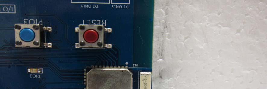
59 -59 of 62- APPENDIX 2 PHOTOGRAPHS OF EUT

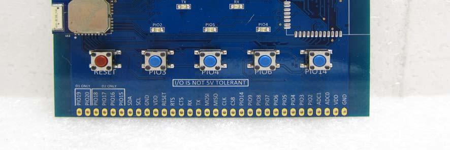
60 -60 of 62- EUT 1 EUT 2


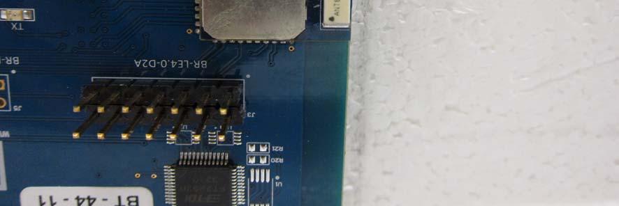
61 -61 of 62- EUT 3 EUT 4 BT Antenna


62 -62 of 62- EUT 5 EUT 6 ~ End of Report ~
BlueRadios BR-LE4.0-D2A N/A. BlueRadios, Inc.
 TEST REPORT of R&TTE (1999/5/EC ) Directive ETSI EN 300 328 V1.7.1: 2006 Product : Brand: Model: Model different: Applicant: Address: BT 4.0 Dual Mode Module BlueRadios BR-LE4.0-D2A N/A BlueRadios, Inc.
EMC Test Report. Client: Crestron Electronics, Inc. Tested by: Jeremy O. Pickens, Senior EMC Engineer
 Test Report Number: 3919823EMC1 Rev. Page: 1 of 26 EMC Test Report Project Number: 3919823 Report Number: 3919823EMC1 Revision Level: Client: Crestron Electronics, Inc. Equipment Under Test: infinet EXTM
FCC ID: IMK-ILCISA EMI TEST REPORT
 15.247 Certification FCC ID: IMK-ILCISA EMI TEST REPORT On SYMPHONY ISA Card Prepared for Proxim 295 N. Bernardo Ave Mountain View, CA 94043 Tel: (650)960-1630 Fax: (650)960-0332 Prepared by Electronic
A Test Lab Techno Corp. FCC. RF Test Report. Product Type. : Mobile Hotspot. Applicant. : Netgear Inc.
 FCC RF Test Report Product Type Applicant : Mobile Hotspot : Netgear Inc. Address : 350 East Plumeria Drive, San Jose, CA 95134 Trade Name Model Number Test Specification : NETGEAR : AC810S-300 : FCC 47
FCC PART 15C TEST REPORT FOR CERTIFICATION On Behalf of NYNE MULTIMEDIA INC. Bluetooth Speaker. Model Number: NYNE VIBE FCC ID: AWA-NYNEVIBE
 FCC PART 15C TEST REPORT FOR CERTIFICATION On Behalf of NYNE MULTIMEDIA INC. Bluetooth Speaker Model Number: NYNE VIBE FCC ID: AWA-NYNEVIBE Prepared for: NYNE MULTIMEDIA INC. 3451 LUNAR COURT, OXNARD,
CONTENTS 1. GENERAL INFORMATION INTRODUCTION PRODUCT INFORMATION DESCRIPTION OF TESTS CHANNEL BANDWIDTH...
 Test Report Number : GETEC-E3-09-083 Page 2 / 33 CONTENTS. GENERAL INFORMATION...4 2. INTRODUCTION...5 3. PRODUCT INFORMATION...6 3. DESCRIPTION OF EUT...6 3.2 SUPPORT EQUIPMENT / CABLES USED...7 3.3 MODIFICATION
CE DFS Test Report. Report No.: EY Page : 1 of 15 Report Version: Rev. 01
 CE DFS Test Report Equipment Model No. Brand Name Applicant Address : Radio Module : SSD45N : Laird Technologies : Laird Technologies : W66N220 Commerce Court, Cedarburg, Wisconsin 53012, USA Standard
FCC Test Report (Class II Permissive Change)
") FCC Test Report (Class II Permissive Change) Product Name Intel Wireless-AC 9560 Model No. 9560NGW FCC ID. 2AKHF9560NG Applicant TONGFANG HONGKONG (SUZHOU) LIMITED Address NO. 83 Wu Lane, Suzhou Industrial
FCC Test Report (Class II Permissive Change) Product Name Intel Wireless-AC 9560 Model No. 9560NGW FCC ID. 2AKHF9560NG Applicant TONGFANG HONGKONG (SUZHOU) LIMITED Address NO. 83 Wu Lane, Suzhou Industrial
CE DFS Test Report. : abgn M.2 module w/usb interface (Refer to item for more details.) (Refer to item for more details.
 (Refer to item for more details.") CE DFS Test Report Equipment Model No. Brand Name Applicant : 802.11abgn M.2 module w/usb interface (Refer to item 1.1.1 for more details.) : M2US50NBT (Refer to item 1.1.1 for more details.) : Laird Technologies
CE DFS Test Report Equipment Model No. Brand Name Applicant : 802.11abgn M.2 module w/usb interface (Refer to item 1.1.1 for more details.) : M2US50NBT (Refer to item 1.1.1 for more details.) : Laird Technologies
Guangzhou Panyu Juda Car Audio Equipment Co.,Ltd. Bluetooth Speaker. Model Number: UB-SPB4M-101 FCC ID: ESXSPB4M
 FCC ID: ESXSPB4M FCC PART 15C TEST REPORT FOR CERTIFICATION On Behalf of Guangzhou Panyu Juda Car Audio Equipment Co.,Ltd. Bluetooth Speaker Model Number: UB-SPB4M-101 FCC ID: ESXSPB4M Prepared for : Guangzhou
FCC PART 15C TEST REPORT FOR CERTIFICATION On Behalf of. Guangzhou Panyu Juda Car Audio Equipment Co.,Ltd. CD/USB RADIO. Model Number: TY-CWU700
 FCC PART 15C TEST REPORT FOR CERTIFICATION On Behalf of Guangzhou Panyu Juda Car Audio Equipment Co.,Ltd. CD/USB RADIO Model Number: TY-CWU700 FCC ID: ESX-CWU700 Prepared for : Guangzhou Panyu Juda Car
SIGFOX END- PRODUCT RADIATED TEST PLAN FOR SIGFOX READY TM CERTIFICATION
 May 23 th 2018 SIGFOX END- PRODUCT RADIATED TEST PLAN FOR SIGFOX READY TM CERTIFICATION Public use Revision History Revision Number Date Author Change description 0.1 August 15 th, 2017 B.Ray Initial spec
FCC PART TEST REPORT SHANGHAI MERIT TECHNOLOGY CORP.
 FCC PART 15.247 TEST REPORT For SHANGHAI MERIT TECHNOLOGY CORP. 1058 TAOGAN RD., SHESHAN TOWN, SONGJIANG DISTRICT, SHANGHAI, China FCC ID: XJ6MT-180H Report Type: Original Report Product Type: 4CH 2.4GHZ
CE DFS Test Report. : abgn PCI-E module
 CE DFS Test Report Equipment Model No. Brand Name Applicant Address : 802.11abgn PCI-E module : SDC-PE15N : Summit : Summit Data Communications, lnc. : 526 South Main Street Suite 805, Akron, Ohio, 44311
BT SOUND BAR. Model Number: AR2010 SBT2014, SBT2014XX, SBT2015,SBT2015XX, ER822FL FCC ID: RI5AR2010
 FCC ID: RI5AR2010 FCC PART 15C TEST REPORT FOR CERTIFICATION On Behalf of Dongguan Earson Audio Technology Co., Ltd BT SOUND BAR Model Number: AR2010 Additional Model:AR2010XX, AR3002, AR3002XX, SBT2014,
FCC Test Report (Class II Permissive Change)
") FCC Test Report (Class II Permissive Change) Product Name 802.11abgn/11ac WLAN + Bluetooth PCI-E Mini Card Model No BCM94360HMB FCC ID QDS-BRCM1082 Applicant Broadcom Corporation Address 190 Mathilda Place
FCC Test Report (Class II Permissive Change) Product Name 802.11abgn/11ac WLAN + Bluetooth PCI-E Mini Card Model No BCM94360HMB FCC ID QDS-BRCM1082 Applicant Broadcom Corporation Address 190 Mathilda Place
ELECTRICAL TESTING FOR:
 ELECTRICAL TESTING 0839.01 Hermon Laboratories Ltd. Harakevet Industrial Zone, Binyamina 30500, Israel Tel. +972-4-6288001 Fax. +972-4-6288277 E-mail: mail@hermonlabs.com TEST REPORT ACCORDING TO: FCC
EUROFINS PRODUCT SERVICE GMBH. Testing Cert # Compliance Test Report FCC PART 15 SUBPART C IC RSS 210 ISSUE 7
 EUROFINS PRODUCT SERVICE GMBH Testing Cert #1983.01 TEST- REPORT Compliance Test Report FCC PART 15 SUBPART C IC RSS 210 ISSUE 7 FCC ID: T7V1315 IC ID: 216Q-1315 Bluetooth module ENW89818C2JF PAN1315 TEST
EMC Test Report. Client: Continental Automotive Systems, Inc. Tested by: Fendy Liauw, Engineering Technician
 Test Report Number: 3953917EMC7 Rev: Page: 1 of 35 EMC Test Report Project Number: 3953917 Report Number: 3953917EMC7 Revision Level: Client: Continental Automotive Systems, Inc. Equipment Under Test:
Shenzhen Zhongjian Nanfang Testing Co., Ltd.
 Report No: CCIS3667. Cover page FCC REPORT (Mobile Phone) Applicant: Address of Applicant: Equipment Under Test (EUT) NETLET ELECTRONICS (HONG KONG) LIMITED 2/F., San Toi Building,37-39 Connaught Road
Test Report. Product Name: Access Point Model No.: MS-6809 FCC ID: DoC
 Test Report Product Name: Access Point Model No.: MS-6809 FCC ID: DoC Applicant : MICRO-STAR INT L Co., LTD Address : No 69, Li-De st., Jung-He City, Taipei Hsien, Taiwan, R.O.C Date of Receipt : June
FCC TEST REPORT For. ETI Solid State Lighting (Zhuhai) Ltd. LED downlight Model No.: XX
 Ltd. LED downlight Model No.: XX") Page 1 of 24 FCC TEST REPORT For ETI Solid State Lighting (Zhuhai) Ltd LED downlight Model No.: 531931XX Prepared for Address Prepared by Address : ETI Solid State Lighting (Zhuhai) Ltd : No.1, Zhongzhu
Page 1 of 24 FCC TEST REPORT For ETI Solid State Lighting (Zhuhai) Ltd LED downlight Model No.: 531931XX Prepared for Address Prepared by Address : ETI Solid State Lighting (Zhuhai) Ltd : No.1, Zhongzhu
FCC Report. Beijing Visual World Technology Co.,Ltd.
 FCC Report Report No.: GTS201703000097F01 Applicant: Beijing Visual World Technology Co.,Ltd. Address of Applicant: 15th Floor and 17th Floor 1701-10A, Building 3, No. 10, Jiuxianqiao Road Jia, Chaoyang
FCC TEST REPORT for Aeon Labs LLC. Aeon Minimote Model No.: DS03202B-ZWUS, DS03202W-ZWUS
 Page 1 of 22 FCC TEST REPORT for Aeon Labs LLC. Aeon Minimote Model No.: DS03202B-ZWUS, DS03202W-ZWUS Prepared for Address Prepared By Address : Aeon Labs LLC. : 121 Buckingham drive, unit36 santa claras
FCC PART TEST REPORT. HHC Changzhou Corp.
 FCC PART 15.249 TEST REPORT For HHC Changzhou Corp. No 61, Xinggang Road, Zhonglou District, Changzhou, Jiangsu, China, 213023 FCC ID: 2AEQWCB20HHC011 Report Type: Original Report Product Type: Control
TEST REPORT FROM RFI GLOBAL SERVICES LTD
 FROM RFI GLOBAL SERVICES LTD Test of: Blighter B422-HPNB Aux Unit FCC ID: UFQB400HPNBAUX To: FCC Part 90: 2010 Subpart F in accordance with RFI Test Plan RFI/REGE1/TP75565JD03 Test Report Serial No: RFI-RPT-RP76945JD15B
FCC Report (WIFI) Red Bear Company Limited. RedBear IoT phat 2ABXJ-PHAT-IOT
 Red Bear Company Limited. RedBear IoT phat 2ABXJ-PHAT-IOT") Report No.: GTS201607000065E01 FCC Report (WIFI) Applicant: Red Bear Company ed Address of Applicant: 1711 Block B, Wah Luen Industrial Centre, 15-21 Wong Chuk Yeung Street, Fo Tan, Hong Kong Equipment
Report No.: GTS201607000065E01 FCC Report (WIFI) Applicant: Red Bear Company ed Address of Applicant: 1711 Block B, Wah Luen Industrial Centre, 15-21 Wong Chuk Yeung Street, Fo Tan, Hong Kong Equipment
CENTRE OF TESTING SERVICE INTERNATIONAL OPERATE ACCORDING TO ISO/IEC FCC ID TEST REPORT
 CENTRE OF TESTING SERVICE INTERNATIONAL OPERATE ACCORDING TO ISO/IEC 17025 FCC ID TEST REPORT TEST REPORT NUMBER : CGZ3150520-00565-EF TEST REPORT For FCC ID 47 CFR PART 15 OCT, 2014 Report Reference No....
FCC PART 22H, PART 24E MEASUREMENT AND TEST REPORT. Shanghai AirM2M Communication Technology Co., Ltd
 FCC PART 22H, PART 24E MEASUREMENT AND TEST REPORT For Shanghai AirM2M Communication Technology Co., Ltd No. 666.East beijing road, Shanghai, China FCC ID: 2AEGG-AIR208 Report Type: Original Report Product
Out of Band Spurious Measurement for Bluetooth Modules
 Products: Signal Analyser FSIQ26/FSP13/FSU8/FSQ26 Out of Band Spurious Measurement for Bluetooth Modules This application notes describes the out of band Spurious emission measurement for Bluetooth modules
FCC Report (WIFI) Shenzhen Reo-link Digital Technology Co., Ltd B509, University Town Business Park LiShan Road, NanShan, Shenzhen, Guangdong, China
 Shenzhen Reo-link Digital Technology Co., Ltd B509, University Town Business Park LiShan Road, NanShan, Shenzhen, Guangdong, China") FCC Report (WIFI) Applicant: Address of Applicant: Manufacturer/y: Address of Manufacturer/y: Equipment Under Test (EUT) Product Name: Shenzhen Reo-link Digital Technology Co., Ltd B509, University Town
FCC Report (WIFI) Applicant: Address of Applicant: Manufacturer/y: Address of Manufacturer/y: Equipment Under Test (EUT) Product Name: Shenzhen Reo-link Digital Technology Co., Ltd B509, University Town
FCC Part 15 Subpart B Test Report. FCC PART 15 Subpart B Class B: 2014
 Shenzhen CTL Electromagnetic Technology Co., Ltd. Tel: +86-755-89486194 Fax: +86-755-26636041 FCC Part 15 Subpart B Test Report FCC PART 15 Subpart B Class B: 2014 Report Reference No...: CTL1408272147-F
FCC Report (WIFI) Shenzhen SDMC Technology Co., Ltd 2AFC2-STB-1HD. * In the configuration tested, the EUT complied with the standards specified above.
 Shenzhen SDMC Technology Co., Ltd 2AFC2-STB-1HD. * In the configuration tested, the EUT complied with the standards specified above.") Report No.: GTSE15080158301 FCC Report (WIFI) Applicant: Shenzhen SDMC Technology Co., Ltd Address of Applicant: 7/F, W2-A Bld, Gaoxin S. Av. 4, Hi-tech Park, Nanshan, Shenzhen, China Equipment Under Test
Report No.: GTSE15080158301 FCC Report (WIFI) Applicant: Shenzhen SDMC Technology Co., Ltd Address of Applicant: 7/F, W2-A Bld, Gaoxin S. Av. 4, Hi-tech Park, Nanshan, Shenzhen, China Equipment Under Test
DFS Test Report RF160715C03A-1. Report No.: PY FCC ID: EX6150v2. Test Model: Received Date: Oct. 21, Test Date: Jun. 01 ~ Jun.
 DFS Test Report Report No.: FCC ID: Test Model: RF160715C03A-1 PY316100334 EX6150v2 Received Date: Oct. 21, 2016 Test Date: Jun. 01 ~ Jun. 07, 2017 Issued Date: Jun. 08, 2017 Applicant: NETGEAR Inc. Address:
TEST REPORT. Test Report No. : UL-RPT-RP C V2.0. Date of Issue: 06 March 2018
 Test Report No. : UL-RPT-RP11913492-2216C V2.0 Manufacturer : Raspberry Pi (Trading) Ltd Model No. : Raspberry Pi 3 Model B+ FCC ID : 2ABCB-RPI3BP Technology : Bluetooth Low Energy Test Standard(s) : FCC
R&TTE EMC TEST REPORT
 No. 1 Workshop, M-10, Middle section, Science & Technology Park, Shenzhen, Guangdong, China 518057 Telephone: +86 (0) 755 2601 2053 Fax: +86 (0) 755 2671 0594 Email: sgs_internet_operations@sgs.com Application
Shenzhen Zhongjian Nanfang Testing Co., Ltd.
 Report No: CCISE8572 Cover Page FCC REPORT (Bluetooth) pplicant: ddress of pplicant: Equipment Under Test (EUT) GROUPSFIT 8/84 route de la Libération 7734 PONTULT COMBULT France Product Name: Model No.:
FCC PART MEASUREMENT AND TEST REPORT FOR. DongGuan City FLYSKY Remote Model Co., Ltd.
 FCC PART 15.249 MEASUREMENT AND TEST REPORT FOR DongGuan City FLYSKY Remote Model Co., Ltd. No.41 Road West, BanHu Village, HuangJiang Town, DongGuan City, GuangDong Porvince, China FCC ID: VPOFLYSKY002
FCC PART 15 CLASS B MEASUREMENT AND TEST REPORT. Tritech Technology Ltd.
 FCC PART 15 CLASS B MEASUREMENT AND TEST REPORT For Tritech Technology Ltd. Unit 8B,Chung pont Commercial Building No.300 Hennessy Road, Wanchai, HongKong Model: 0-545-24967-8, 0-545-24986-4 Report Type:
CHAO WEI ELECTRONICS CO., LTD. FCC REPORT CHAO WEI ELECTRONICS CO., LTD.
 CHAO WEI ELECTRONICS CO., LTD. FCC REPORT Prepared For : CHAO WEI ELECTRONICS CO., LTD. No.8, Xianglong Road, Xiagang, Changantown, Dongguan City, China Product Name: Model : DVB-T ANTENNA CW-DVB66, CW-DVB83,
TEST REPORT. Report Number: MPK-003B Project Number: G October 20, 2017
 TEST REPORT Report Number: 13224477MPK-3B Project Number: G13224477 October 2, 217 Testing performed on the FIBERGATEWAY Model Number: GR24BG FCC ID: 2ACJF-FGW-GR24BG to FCC Part 15, Subpart E For Altice
Testing. Maker Works. Applicant: Model No.: FCC ID: Jun., May to 16. Date of Test: PASS* Test Result: Signature: Authorized. this report.
 1 Cover Page Shenzhen Zhongjian Nanfang Testing Co., Ltd. FCC REPORT Applicant: Address of Applicant: Maker Works Technology INC Building C3, Floor 4th, Zhiyuan, Xili, Nanshan District, ShenZhen 518057
Project: IEEE P Working Group for Wireless Personal Area Networks (WPANs)
") Project: IEEE P802.15 Working Group for Wireless Personal Area Networks (WPANs) Title: [Radio Specification Analysis of Draft FSK PHY] Date Submitted: [11 March 2012] Source: [Steve Jillings] Company:
Project: IEEE P802.15 Working Group for Wireless Personal Area Networks (WPANs) Title: [Radio Specification Analysis of Draft FSK PHY] Date Submitted: [11 March 2012] Source: [Steve Jillings] Company:
RF Test Report: Airspan ib440 to 47CFR SC_TR_150_B
 RF Test Report: irspan ib44 to 47CFR5.247 FCC ID: O2J-iB44 SC_TR_5_B Prepared for: irspan Communications Ltd Capital Point, 33 Bath Road Slough, Berkshire SL 3UF Sulis Consultants Limited Mead House, Longwater
FCC Test Report (Bluetooth)
") Report No.: T479F Page: of 52 FCC Test Report (Bluetooth) FCC ID : 8IVOOMBOX-ONGO pplicant : Shenzhen DIVOOM Technology Co., Ltd. 3, 2nd Floor, Block, Zhengxing Building, No. 33 Taizi Road, Shekou, Nanshan
Report No.: T479F Page: of 52 FCC Test Report (Bluetooth) FCC ID : 8IVOOMBOX-ONGO pplicant : Shenzhen DIVOOM Technology Co., Ltd. 3, 2nd Floor, Block, Zhengxing Building, No. 33 Taizi Road, Shekou, Nanshan
TEST REPORT. Test Report No. : UL-RPT-RP JD18L V2.0. Manufacturer : Neeo AG. Model No. : 6336-BRAIN FCC ID : 2AKK7-BR633601
 TEST REPORT Test Report No. : UL-RPT-RP11456397JD18L V2.0 Manufacturer : Neeo AG Model No. : 6336-BRAIN FCC ID : 2AKK7-BR633601 Test Standard(s) : FCC Part 15.207 1. This test report shall not be reproduced
Test Report. Product Name : PC2PC-Bluetooth Model No. : MS-6967 FCC ID. : I4L-MS6967
 Test Report Product Name : PC2PC-Bluetooth Model No. : MS-6967 FCC ID. : I4L-MS6967 Applicant : MICRO-STAR INT'L Co., LTD. Address : No. 69, Li-De St, Jung-He City, Taipei Hsieh, Taiwan, R.O.C. Date of
CENTRE OF TESTING SERVICE INTERNATIONAL
 CENTRE OF TESTING SERVICE INTERNATIONAL OPERATE ACCORDING TO ISO/IEC 17025 IC TEST REPORT TEST REPORT NUMBER : CGZ3150202-00095-E A101,No.65,Zhuji Highway,Tianhe District,Guangzhou, Guangdong, China TEST
REPORT Datum/Date Beteckning/Reference Sida/Page
 2002-10-25 F219009-F24 1 (1) FCC ID: B5KPROJ1192211-1 Rev. 2003-01-16 Encl. 1 Description - Equipment Under Test (EUT) Equipment: Tx Frequency range: Tested Channel: WCDMA Base station transceiver 1900
Report No.: CAT-012
 Conformance Test Report for EN301 406 V1.5.1 (2003-07) Digital Enhanced Cordless Telecommunic. (DECT); Harmonized EN for Digital Enhanced Cordless Telecommunications(DECT) covering essential requirements
TEST REPORT FROM RFI GLOBAL SERVICES LTD
 TEST REPORT FROM RFI GLOBAL SERVICES LTD Test of: D-MINI-2108-2019 FCC ID: NEO-DMINI21082019 To: FCC Parts 2.1046; 2.1049; 22.913(a); 22.917; 24.232; 24.238 & 15.107 3GPP TS 36.143 V10.3.0 This Test Report
e2b calibration 521 Fifth Avenue Chardon, Ohio Phone: Fax: Certificate Of Calibration
 e2b calibration certifies that the above listed instrument at the time of calibration meets or exceeds all specifications as stated in the referenced procedure (unless otherwise noted). It has been calibrated
Report No.: CAT-012-1
 Conformance Test Report for EN301 406 V1.5.1 (2003-07) Digital Enhanced Cordless Telecommunic. (DECT); Harmonized EN for Digital Enhanced Cordless Telecommunications(DECT) covering essential requirements
Bluetooth Tester CBT. Specifications. Specifications. Version January 2006
 Specifications Version 03.00 Bluetooth Tester CBT January 2006 Specifications CONTENTS UNIT SPECIFICATIONS...3 TIMEBASE TCXO...3 REFERENCE FREQUENCY INPUT...3 RF GENERATOR...3 RF ANALYZER...5 Power meter
CONTENTS 6.2 TEST SET-UP...16
 CONTENTS 1. GENERAL INFORMATION...3 2. INTRODUCTION...4 3. PRODUCT INFORMATION...5 3.1 DESCRIPTION OF EUT...5 3.2 SUPPORT EQUIPMENT / CABLES USED...6 3.3 MODIFICATION ITEM(S)...6 4. DESCRIPTION OF TESTS...7
FCC TEST REPORT D-LINK CORPORATION
 FCC TEST REPORT REPORT NO.: RF921014R02 MODEL NO.: DWL-120(refer to page 6 for other models) RECEIVED: October 14, 2003 TESTED: October 16 ~ October 17, 2003 APPLICANT: ADDRESS: D-LINK CORPORATION NO.8,
FCC 47 CFR PART 15 SUBPART C & INDUSTRY CANADA RSS-210 TEST REPORT. For. Dual-Band Wireless VPN Router with GbE Switch.
 FCC 47 CFR PART 15 SUBPART C & INDUSTRY CANADA RSS-210 TEST REPORT For Dual-Band Wireless VPN Router with GbE Switch Model: RV220W Trade Name: CISCO Issued to SerComm Corporation 8F, No. 3-1, YuanQu St.,
FCC Radio Test Report
 Shenzhen Toby Technology Co., Ltd. Report No.: TB-FCC163268 Page: 1 of 153 FCC Radio Test Report FCC ID: 2AL8K-H5 Report No. : TB-FCC163268 Original Grant Applicant : NZS Inc. DBA Clary Icon Equipment
CERTIFICATION APPLICATION TEST REPORT
 BEC INCORPORATED CERTIFICATION APPLICATION TEST REPORT TEST STANDARDS: FCC Part 15 Subpart C, Section 15.247 Intentional Radiator ARRIS Model VMS4100 Set Top Box FCC ID: ACQ-VMS4100 REPORT BEC-1792-02
LAB CODE 571- Page No.: of 11 Measurement System Information General Information Testing Condition: Temperature: 5±3 C Humidity: <8% Measurement Facil
 LAB CODE 571- Issued Date: July, 11 Page : 1 of 11 Antenna Test Report Test Plan: Non-compliance with ISO175 Applicant Name: EGIGA TECHNOLOGIES CO LTD Manufacturer Name: EGIGA TECHNOLOGIES CO LTD / STOLLMANN
FCC PART 15 TEST REPORT
 FCC PART 15 TEST REPORT for Huawei Technologies Co.,Ltd tablet Model Name: T1-A1w FCC ID: QIST1-A1W with Hardware Version: SH1T1A1LM Software Version: T1-A1wV1R1C1 Issued Date: 15--15 TESTING CNAS L57
THRU Lab & Engineering , Hager-Ri, Yoju-Up, Yoju-Gun Kyunggi-Do, , Korea T /F
 Test Report Product Name: IQ Pager (Receiver) FCCID: WDC-IQ2008 Model No.: IQ2008 Applicant: HME Wireless, Inc. 1400 Northbrook Parkway, Suite 320, Suwanee City, GA, 30024, U.S.A Date Receipt : 12/20/2008
THRU Lab & Engineering , Hager-Ri, Yoju-Up, Yoju-Gun Kyunggi-Do, , Korea T /F
 Test Report Product Name: IQ Pager (Receiver) FCCID: WDC-IQ2008 Model No.: IQ2008L Applicant: HME Wireless, Inc. 1400 Northbrook Parkway, Suite 320, Suwanee City, GA, 30024, U.S.A Date Receipt : 12/20/2008
Test Report. Model No.: NF592XX-YYYY-ZZ(X,Y & Z: Stands for A-Z & 0-9 ) HBJC1XXF592-YYYY-ZZ (X,Y & Z: Stands for A-Z & 0-9 )
 HBJC1XXF592-YYYY-ZZ (X,Y & Z: Stands for A-Z & 0-9 )") Test Report Applicant: Product Name: Brand Name: Jetway Information Co.,Ltd Motherboard/Barebone N/A Model No.: NF592XX-YYYY-ZZ(X,Y & Z: Stands for A-Z & 0-9 ) HBJC1XXF592-YYYY-ZZ (X,Y & Z: Stands for
Test Report Applicant: Product Name: Brand Name: Jetway Information Co.,Ltd Motherboard/Barebone N/A Model No.: NF592XX-YYYY-ZZ(X,Y & Z: Stands for A-Z & 0-9 ) HBJC1XXF592-YYYY-ZZ (X,Y & Z: Stands for
TABLE OF CONTENTS 1. GENERAL INFORMATION PRODUCT DESCRIPTION FOR EQUIPMENT UNDER TEST (EUT) TEST STANDARDS TEST METHODOLOGY
 TEST STANDARDS TEST METHODOLOGY") FCC Rule(s): FCC Part 15B Measurement and Test Report Product Description: Tested Model: Report No.: For GlobTek, Inc. 186 Veterans Dr. Northvale, NJ 07647 USA FCC Part 15 Subpart B X-PLORE 8000 STANDARD
FCC Rule(s): FCC Part 15B Measurement and Test Report Product Description: Tested Model: Report No.: For GlobTek, Inc. 186 Veterans Dr. Northvale, NJ 07647 USA FCC Part 15 Subpart B X-PLORE 8000 STANDARD
FCC PART 15B, CLASS B TEST REPORT. Autel Intelligent Tech. Corp., Ltd.
 FCC PART 15B, CLASS B TEST REPORT For Autel Intelligent Tech. Corp., Ltd. 6th - 10th Floor, Bldg. B1, Zhiyuan, Xueyuan Rd., Xili, Nanshan Shenzhen China FCC ID: WQ8MAXISYSMY906 Report Type: Original Report
FCC TEST REPORT North Mathilda Avenue, Sunnyvale, California Advance Data Technology Corporation
 FCC TEST REPORT REPORT NO.: RF931119H01 NO.: RECEIVED: Nov. 19, 2004 TESTED: Dec. 22, 2004 to Jan. 05, 2005 ISSUED: Jan. 17, 2005 APPLICANT: ADDRESS: Juniper Networks 1194 North Mathilda Avenue, Sunnyvale,
FCC PART 15 TEST REPORT
 FCC PART 15 TEST REPORT No. I17Z60314SRD06 for HMD Global Oy Smart Phone TA-1033 with FCC ID: 2AJOTTA-1033 Hardware Version: 3 Software Version: 000C_3_050 Issued Date: 2017-04-17 Note:The test results
EMC Test Report. 850 Kacena Road Hiawatha, IA 52233
 EMC Client: EUT: Crystal Group 850 Kacena Road Hiawatha, IA 52233 Model RS112 No.: R20140819-21 Approved By: Nic S. Johnson, NCE EMC Test Engineering Manager/Technical Manager inarte Certified EMC Engineer
SIGFOX RADIATED PERFORMANCE SPECIFICATION
 September 17 th 2018 SIGFOX RADIATED PERFORMANCE SPECIFICATION Public use Revision History Revision Number Date Author Change description 0.1 August 15 th, 2017 B.Ray Initial spec 0.2 October 5 th, 2017
Sunlight Supply, Inc.
 FCC Part 18 Subpart C Consumer For RF Lighting Equipment Electromagnetic Compatibility Test Report Sunlight Supply, Inc. Etelligent Compatible Ballast - olt July 19, 2017 Tests Conducted by:, LLC 20811
FCC REPORT Q6WBT * In the configuration tested, the EUT complied with the standards specified above.
 1 Cover Page Report No: CCIS12110026101 FCC REPORT Applicant: Address of Applicant: Equipment Under Test (EUT) GUANGDONG STEELMATE SECURITY CO., LTD Renan Street, Dong fu Road, Dongfeng Town,Zhongshan,
R&S WMS32 Wireless Measurement System Software Specifications
 R&S WMS32 Wireless Measurement System Software Specifications Data Sheet Version 03.00 8 CONTENTS General... 3 Software version... 3 System requirements... 3 Options for the R&S TS8997 test system with
TOBY-L200 GSM/UMTS/HSPA/LTE Data Module
 FCC Measurement/Technical Report on TOBY-L200 GSM/UMTS/HSPA/LTE Data Module FCC ID: XPYTOBYL200 IC:8595A-TOBYL200 Report Reference: MDE_UBLOX_1408_FCCd according to FCC Part 27, Subpart C Test Laboratory:
FCC PART RSS-GEN, ISSUE 5, APRIL 2018 RSS-247, ISSUE 2, FEBRUARY 2017 TEST REPORT SZ DJI TECHNOLOGY CO., LTD
 FCC PART 5.247 RSS-GEN, ISSUE 5, APRIL 208 RSS-247, ISSUE 2, FEBRUARY 207 TEST REPORT For SZ DJI TECHNOLOGY CO., LTD 4th floor, West Wing, Skyworth Semiconductor Design Building NO.8 Gaoxin South 4th Ave,
T E S T - R E P O R T. No for. SLG 42 MOBY Component
 Straubing, August 04, 1998 T E S T - R E P O R T No. 51905-80643-0 for SLG 42 MOBY Component Applicant: Purpose of Testing: Siemens AG To show compliance with FCC Rules Part 15, Subpart C section 15.209
FCCC RF : ZTE APPLICANT EQUIPMENT BRAND NAME MODEL NAME FCC ID STANDARDD : WF722. The product was SPORTON. Page Number (KUNSHAN) INC.
 INC.") FCC RF Test Report 7 FCCC RF Test Report PPLICNT EQUIPMENT BRND NME MODEL NME FCC ID STNDRDD CLSSIFICTION : ZTE CORPORTION : HOME PHONE : ZTE : WF722 : SRQ-WF722 : FCC 47 CFR Part 2, 22(H), 24(E) : PCS
FCC RF Test Report 7 FCCC RF Test Report PPLICNT EQUIPMENT BRND NME MODEL NME FCC ID STNDRDD CLSSIFICTION : ZTE CORPORTION : HOME PHONE : ZTE : WF722 : SRQ-WF722 : FCC 47 CFR Part 2, 22(H), 24(E) : PCS
Page: 1 of 15 FCC TEST REPORT. : MEGAVIEW DIGITECH LIMITED : C Fu Gui Yuan, Block 80, Bao an District, Shenzhen, China
 Page: 1 of 15 FCC TEST REPORT Reference No. Applicant Address : WT10125265-S-E-F : MEGAVIEW DIGITECH LIMITED : C1-1001 Fu Gui Yuan, Block 80, Bao an District, Shenzhen, China Equipment Under Test (EUT)
T E S T - R E P O R T. No for PC24E-11-FC/R. RF-modem for wireless LAN. Agere Systems Nederland B.V.
 EMV-Prüfzentrum EMI/EMC-Testcenter Straubing, September 5, 2001 T E S T - R E P O R T No. 56305-10552-1 for RF-modem for wireless LAN Purpose of testing: To show compliance with FCC Code of Federal Regulations,
Order Number : GETEC-C FCC Part 15 subpart B Test Report Number : GETEC-E Page 2 / 32 CONTENTS
 Test Report Number : GETEC-E3-12-032 Page 2 / 32 CONTENTS 1. GENERAL INFORMATION... 3 2. INTRODUCTION... 4 3. PRODUCT INFORMATION... 5 3.1 DESCRIPTION OF EUT... 5 3.2 SUPPORT EQUIPMENT / CABLES USED...
CERTIFICATION APPLICATION TEST REPORT
 BEC INCORPORATED CERTIFICATION APPLICATION TEST REPORT TEST STANDARDS: FCC Part 15 Subpart C, Section 15.247 Intentional Radiator ARRIS Model VMS4100 Set Top Box FCC ID: ACQ-VMS4100 REPORT BEC-1792-03
Report On. FCC Testing of the Pace Plc 16x4 Hybrid Gateway Cable Set Top Box COMMERCIAL-IN-CONFIDENCE
 Report On FCC Testing of the Pace Plc 16x4 Hybrid Gateway Cable Set Top Box Document 75926325 Report 01 Issue 1 April 2014 TÜV SÜD Product Service, Octagon House, Concorde Way, Segensworth North, Fareham,
Lab Wireless Mathematics
 Lab 3.2.3 Wireless Mathematics Estimated Time: 25 minutes Number of Team Members: Students will work in teams of two or individually Objective In this lab, the student will learn the importance of the
S t a t e m e n t. of Opinion. No: /AA/00
 S t a t e m e n t of Opinion No: 10214085/AA/00 With respect to Chapter 10 of the Telecommunications Act of The Netherlands, Telefication declares that to our opinion the listed product complies with the
VXIbus Microwave Downconverter
 1313B Phase Matrix, Inc ṬM Instruments You Can Count On VXIbus Microwave Downconverter High-Performance Downconversion For Analysis of Microwave Signals 1 MHz to 26.5 GHz Frequency Range -135 to +30 dbm
FCC PART TEST REPORT. Hantat Technology Ltd.
 FCC PRT 5.247 TEST REPORT For Hantat Technology Ltd. 3/F., C Building, Fuxinlin Industrial Park, Hangch,Xixiang Town, Banan District,Shenzhen,China,5826 FCC ID: V3NHB67 Report Type: Original Report Product
Test Report. Applicant Address. : WALTOP International Corp. : 6F,No.19-1 Industry E.Rd.IV,Hsinchu Science Park,Hsin-Chu 30077,Taiwan,R.O.C.
 Test Report Product Name : Tablet: Wireless Tablet X86/X86; Dongle: Wireless Tablet Receiver X86/X86 Model No. : Tablet: RCK-T7, RCK-T7S; Dongle: RCK-T7R, RCK-T7RS FCC ID. : Tablet: UBBRCKT7, Dongle: UBBRCKT7R
STC (Dongguan) Company Limited EC VERIFICATION OF COMPLIANCE EMC-D163584VOC
 Company Limited EC VERIFICATION OF COMPLIANCE EMC-D163584VOC") EC VERIFICATION OF COMPLIANCE Reference Number: Applicant: EMC-D16584VOC Zhuhai Zhi Li Battery Co., Ltd. 7/F., Building 10, Xiang Zhou North Industry Park, Zhuhai, GD 519002, China Description: Zinc Air
EC VERIFICATION OF COMPLIANCE Reference Number: Applicant: EMC-D16584VOC Zhuhai Zhi Li Battery Co., Ltd. 7/F., Building 10, Xiang Zhou North Industry Park, Zhuhai, GD 519002, China Description: Zinc Air
C-MAX. CMM-9301-V3.1S Bluetooth 4.0 Single Mode HCI Module. Description. 1.1 Features
 Description This Module is limited to OEM installation ONLY The module is a Bluetooth SIG qualified, miniaturised BLE controller module based on EM Microelectronic's low power fully integrated single-chip
Improving the accuracy of EMI emissions testing. James Young Rohde & Schwarz
 Improving the accuracy of EMI emissions testing James Young Rohde & Schwarz Q&A Who uses what for EMI? Spectrum Analyzers (SA) Test Receivers (TR) CISPR, MIL-STD or Automotive? Software or front panel?
Test result 1. Conducted emission EN 55022: A1:2007 EA 3 passed 2. Radiated emission <1GHz (others)
") SHARP EMC Testing Laboratory Test Report No.: 11/250-02 page TR-2 of TR-13 5 SUMMARY OF TEST RESULTS Emission testing No. Item Test procedure Page code Number of pages Test result 1. Conducted emission
SHARP EMC Testing Laboratory Test Report No.: 11/250-02 page TR-2 of TR-13 5 SUMMARY OF TEST RESULTS Emission testing No. Item Test procedure Page code Number of pages Test result 1. Conducted emission
TEST REPORT No
 D-PL-12076-01-00 TEST REPORT No. 3-20835062 Applicant Equipment under test Kathrein Automotive GmbH & Co. KG LTE Kompensator US; 6803145-01 218898-10 50110260 FCC-ID: 2ACC7LTECOMPB0 Test Standard(s) FCC
Product Introduction. Duplexer Box MN2555A. Signal Analyzer MS2830A. Ver.1.0
 Product Introduction Duplexer Box MN2555A Signal Analyzer MS2830A Ver.1.0 Duplexer Box MN2555A Duplexer Box MN2555A Connecting MN2555A, Signal Analyzer MS2830A, and USB Power Sensor *The shape of the accessory
AW900mT. User s Manual. Point-to-multipoint. Industrial-grade, ultra-long-range 900 MHz non-line-of-sight wireless Ethernet systems
 User s Manual Point-to-multipoint Industrial-grade, ultra-long-range 900 MHz non-line-of-sight wireless Ethernet systems User s Manual Non-line-of-sight :: 900 MHz Thank you for your purchase of the multipoint
TEST REPORT CHOMERICS R&D. PREMIER EMI Shielding Thermoplastic Face Plate Shielding Effectiveness 84 DRAGON COURT WOBURN, MA 01801
 TEST REPORT CHOMERICS PREMIER EMI Shielding Thermoplastic Face Plate Shielding Effectiveness Prepared by: CHOMERICS R&D 84 DRAGON COURT WOBURN, MA 01801 Date: May 2006 Test Report Number: TR 1011 EN05/06
FCC test report. Via Pezza Alta, 13 I Rustignè di Oderzo (TV)
") Test report nr. 20811FCC11 Measurements performed in accordance with: FCC Rules: code of Federal Regulations (CFR) no. 47 PART 15 RADIO FREQUENCY DEVICES Product: Tested model: FCC ID Applicant: Manufacturer:
Test report nr. 20811FCC11 Measurements performed in accordance with: FCC Rules: code of Federal Regulations (CFR) no. 47 PART 15 RADIO FREQUENCY DEVICES Product: Tested model: FCC ID Applicant: Manufacturer:
Shenzhen Zhongjian Nanfang Testing Co., Ltd.
 Report No: CCIS15010007003 1 Cover Page FCC REPORT Applicant: Address of Applicant: Interglobe Connection Corp 7500 NW 25 th Street 112 Miami, Florida 33122 USA Equipment Under Test (EUT) Product Name:
Table of Contents 1. GENERAL INFORMATION SYSTEM TEST CONFIGURATION CONDUCTED EMISSIONS TEST RADIATED EMISSION TEST...
 Table of Contents. GENERL INFORMTION... 5. PRODUCT DESCRIPTION FOR EQUIPMENT UNDER TEST... 5.2 RELTED SUBMITTL(S) / GRNT (S)... 5.3 TEST METHODOLOGY... 8.4 EQUIPMENT MODIFICTIONS... 8.5 SUPPORT DEVICE...
FCC Part 15B Test Report
 Shenzhen Toby Technology Co., Ltd. Report No.: TB-FCC111757 Page: 1 of 18 FCC Part 15B Test Report Application No. : TB11081419 Applicant : Ingtron Enterprise Co., Ltd. Equipment Under Test (EUT) EUT Name
PM Series Microwave Power Calibration System
 PM Series Microwave Power Calibration System Supports Sensors from most major manufactures up to 50 GHz Faster than direct compare method Lowest total uncertainty National Metrology Institute class thermistor