Setting up the Setting up the Dragonfly 1 v June
|
|
|
- Robert Black
- 6 years ago
- Views:
Transcription


1 Setting up the 1
2 Introduction In this guide we'll be setting up a rather complete observatory, integrating in the Dragonfly all relevant elements: Roof, motorized with a garage-door system and including two limit switches Mount, controlling its parked position CCD camera Automatic focusing equipment Roof / observatory lights Fans (mirror cooling) Scope cover (Snap Cap) Flat foil (included in the Snap Cap) This should cover most needs, and be clear enough so changes can be easily made. Also, please note we'll be focusing on the wiring and physical installation details, things not deeply addressed in the user's guide. For software configuration and other topics have the user's guide handy. Be warned, though, that some of the steps here involve wiring things that will carry mains electricity if you don't feel 100% comfortable doing so, seek the advice of a qualified electrician. Tooling We'll be doing very basic operations, and all can be accomplished with just cutting pliers; a cable peeling (stripper) tool will be nice to have, too. Other than that, just a small flat screwdriver (for the Dragonfly terminal plugs), and whatever you may need for installing the limit switches and distance sensor. 2

, and check you can open and close relays using the software.")
3 Initial steps First of all we have to decide where the Dragonfly is going to be installed. There's no need for it to be close to the scope, but to avoid too long power cables a nice place is probably near the scope pier. All cables are going to converge at this place, from the limit switches, power, network cable, etc. Before starting installing and wiring all peripherals the Dragonfly will be controlling, connect it to the network and power (12V d.c.), and check you can open and close relays using the software. Please refer to the Dragonfly user's manual if you need advice regarding this. Roof position sensors (limit switches) This is very observatory-dependent; we need to have one switch active (closed) when the roof is open, other switch active when it is closed. You can use whatever kind of switch you prefer; we favor the magnetic, contactless ones, but other kind of switch will do, too. This kind of switches (there are many versions) are quite nice as they provide some play and thus don't need exact roof positioning. If you were using this model, connect the wires to the common (C) and normally open (NO) contacts. Our magnetic switches are supplied standard with a 3 m. cable (you can ask for different lengths to tidy up things). 3

4 Install both limit switches, connect the roof open switch to sensor in 1, roof closed to sensor in 2. By the way, no polarity, you can connect any switch wire to any of the +5 or In plugs in the Dragonfly. With the software, confirm the sensor 1 becomes active when the roof is open (inactive otherwise), same for sensor 2 and a closed roof. 4

.")
5 Mount position sensor Again, you can use any sensor of your preference, for this guide we are going to use the Sharp IR distance sensor. Find a convenient place for the sensor (in my case, and many others, just checking the mount counterweight position is enough for roof safety, so I placed it in the pier). Wiring it is really simple; just note the color near the tip of each cable: one should be green (and/or) blue (ground), other red (and/or) brown (+5V) and last one white (sensor out). 5


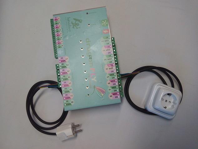
6 The ground one (green/blue) one has to go to one of the 4 ground plugs (placed at the right of the sensor IN 8 ); The red and white will go to a normal sensor - for convenience, it is suggested to use the sensor 8; so, red to sensor 8 +5V, white to sensor 8 In, blue to ground. Now it's time to calibrate the sensor, please refer to the Remote control addenda: analog sensors (point 4-c of current version) in the Dragonfly user's manual. At this point we've setup all sensors we're going to use; let's advance into controlling the electrical devices. Roof motor Our roof motor should have the option of having a wall mounted switch to manually open and close it push to activate, it will open or close alternatively each time. Instead of the wall switch (or in addition to it), we'll have the Dragonfly in charge. Again very simple, both wires from the motor system will go to the power out, relay 1 (using COM and NO, again no polarity), in the input side, as we are not powering the roof motor (it is to be powered independently of the Dragonfly), but just activating it, pushing a button, we'll short a terminal plug, as in the image: 6


7 This way, when we close the relay, the circuit will close and the roof will start moving. With the software, configure this relay as pulsed, with any reasonable period (2 seconds, that is, 2000ms works nice). 7

8 Other devices Wiring the rest of items we want to control is very much the same for all of them, with a little exception for the observatory lights. For each of them we'll cut the AC cable and wire it, both sides, to the Dragonfly 1. Once cut, the wires from the plug side will go to the power in of the Dragonfly, the other part, attached to the power supply, to the power out. The cable color codes vary from country to country, but commonly: protective earth (or protective ground) will be green/yellow stripped neutral either blue or black phase brown or red In case of doubt, please check 1 If you don't like the idea of cutting the power supply wires (voiding the warranty in the process), it's easy to make Dragonfly controlled plug for each device. Check the addenda for detailed instructions. 8


 Flat foil (included in the Snap Cap) Scope cover (Snap Cap) By the way, for devices with earth / protective")
9 We'll wire neutral to common (COM), phase to IN (input side) and to NO (output side). If there's no ground as in the power supply image, no problem at least one of them should have it, to have the Dragonfly itself grounded. Do the same for all devices, so the relays are wired: 1: 2: 3: 4: 5: 6: 7: 8: to roof open / close button mount power supply CCD camera power supply Roof / observatory lights (see note below) Automatic focusing equipment Fans (mirror cooling) Flat foil (included in the Snap Cap) Scope cover (Snap Cap) By the way, for devices with earth / protective ground, to have all 3 wires aligning properly, cut the neutral and phase ones at least 70mm long, and the earth one 15mm shorter. 9
 connection in the power supply at relay 3.")
10 Relay 4, being the lights, are the exception to the rule, as we want them off while the scope is working, so, instead of wiring the phase wire to NO, just wire it to NC. Image taken just after wiring the observatory lights note the COM-NC connection, as opposed to the rest of the relays. Also notice the grounded (earthed) connection in the power supply at relay 3. All protective ground inputs and outputs are shared and connected to the box of the Dragonfly. 10


11 Another way of setting up things Instead of cutting etc the power supplies of the different devices, you may prefer to wire one or several plug / socket pairs to the Dragonfly. This is more versatile but also means more things around, so I think it's a matter of personal preference. In this case, follow these steps:
12 Final. 12
13 Final thoughts I've described how I'd setup an observatory basically, what I did with mine. You can opt to group several things in one relay for instance, the mount and CCD as both will be usually powered on and off at the same time. Also you could cut the power supply at the low voltage, DC side; if you feel uncomfortable doing as I proposed, danger of handling mains voltage etc, by all means do so. The main drawback of this (cutting at the DC side) is the marginal power consumption of the power supplies even when not powering anything. I'm publishing a set of scripts to handle this very same configuration, they are available from: Download, open the compressed file, and check the readme file. 13
Dragonfly - Users manual v. 1.2
 Dragonfly Users manual 1 Index 1) Introduction 2) Planning 3) Electrical setup 4) Software 4-a) Installation 4-b) Connecting 4-c) Remote control Addenda: analog sensors 4-d) Automated control ASCOM 4-e)
Firefly. Users manual
 Firefly Users manual Firefly - Users manual v. 1.2 1 10/Feb/2013 I n d e x 1. Overview 2. Planning 3. Electrical setup 4. Software 4-A) Remote control Addenda: analog sensors 4-B) Automated control - ASCOM
ImproX (TRT) Twin Remote Terminal INSTALLATION MANUAL
 Twin Remote Terminal INSTALLATION MANUAL") SPECIFICATIONS MODEL NUMBER: XRT910-0-0-GB-XX XRT911-0-0-GB-XX XTT911-0-0-NN-XX IMPROX TRT ImproX (TRT) Twin Remote Terminal INSTALLATION MANUAL Working Environment XRT910-0-0-GB-XX... (Aluminium Extruded
SPECIFICATIONS MODEL NUMBER: XRT910-0-0-GB-XX XRT911-0-0-GB-XX XTT911-0-0-NN-XX IMPROX TRT ImproX (TRT) Twin Remote Terminal INSTALLATION MANUAL Working Environment XRT910-0-0-GB-XX... (Aluminium Extruded
HS-509 VIBRATION TRIP MODULE
 HS-509 VIBRATION TRIP MODULE 1. Overview The HS-509 is a configurable trip amplifier capable of accepting a 4-20mA signal from a HS-420 sensor and providing two trip action relay outputs along with an
HDMI over Wireless Extender p
 HDMI over Wireless Extender - 1080p Product ID: ST121WHD2 This HDMI over wireless extender lets you transmit your audio / video signal from an HDMI source to a remote display located up to 165 ft (50m)
Bill of Materials: Super Simple Water Level Control PART NO
 Super Simple Water Level Control PART NO. 2169109 Design a simple water controller in which electrodes are required to sense high and low water levels in a tank. Whenever the water level falls below the
Wall Plate HDMI over CAT5 Extender with Power Over Cable 1080p 165ft (50m)
") Wall Plate HDMI over CAT5 Extender with Power Over Cable 1080p 165ft (50m) Product ID: ST121HDWP The ST121HDWP HDMI over CAT5 Extender Wall Plate Kit lets you extend your HDMI audio/video up to 165 feet
Wall Plate HDMI over CAT5 Extender with Power Over Cable 1080p 165ft (50m) Product ID: ST121HDWP The ST121HDWP HDMI over CAT5 Extender Wall Plate Kit lets you extend your HDMI audio/video up to 165 feet
Operating Instructions for Throttle Valves Using VRC Valve Positioner
 ThrottleMaster TM Operating Instructions for Throttle Valves Using VRC Valve Positioner p/n: X709116 $10.00 3/2012 Throttlemaster is a registered trademark of Vacuum Research Corporation Introduction The
Integre4. Audiophile integrated amplifier. v1.2
 Owner s Manual Integre4 Audiophile integrated amplifier www.lab12.gr v1.2 Table of Contents It is yours Features Unpacking and Warnings Installation & Placement Front Panel Rear Panel Connections Remote
Inputs and outputs. Connecting leads. Buzzer
 Inputs and outputs Mr Bit experiments are designed to help younger pupils get started with connecting sensors and devices to the BBC micro:bit. They are useful 'warm-up' activities before attempting Mr
HDMI over CAT5 HDBaseT Extender - Power over Cable - Ultra HD 4K
 HDMI over CAT5 HDBaseT Extender - Power over Cable - Ultra HD 4K Product ID: ST121HDBTE The StarTech.com HDBaseT extender kit, extends HDMI up to 230 feet (70 Meters) over a single CAT5e or CAT6 cable.
TV Lift System Model CL-65 Installation Instructions
 TV Lift System Model CL-65 Installation Instructions Contact: Support@Nexus21.com Toll Free: (866) 500-5438 Phone: (480) 951-6885 Fax: (480) 951-6879 Revised: 01/17/17 Below is a parts list describing
ALO 030 MKII. 30 Watt DMX LED scanner. User manual
 ALO 030 MKII 30 Watt DMX LED scanner User manual Safety instructions WARNING! Always keep this device away from moisture and rain! Hazardous electrical shocks may occur! WARNING! Only connect this device
TRANSCENSION 6-CHANNEL DMX DIMMER PACK (order code: BOTE40) USER MANUAL
 USER MANUAL") www.prolight.co.uk TRANSCENSION 6-CHANNEL PACK (order code: BOTE40) USER MANUAL SAFETY WARNING FOR YOUR OWN SAFETY, PLEASE READ THIS USER MANUAL CAREFULLY BEFORE YOUR INITIAL START-UP! CAUTION! Keep this
www.prolight.co.uk TRANSCENSION 6-CHANNEL PACK (order code: BOTE40) USER MANUAL SAFETY WARNING FOR YOUR OWN SAFETY, PLEASE READ THIS USER MANUAL CAREFULLY BEFORE YOUR INITIAL START-UP! CAUTION! Keep this
Safety FIND THE FEED CABLE IN YOUR ELECTRICITY METER (UK)
") How to contact us: If you have any questions about using your Efergy monitor, or if you'd like further advice about energy saving at home or at work, please feel free to contact us: Call Efergy on +44
How to contact us: If you have any questions about using your Efergy monitor, or if you'd like further advice about energy saving at home or at work, please feel free to contact us: Call Efergy on +44
HDMI Over IP Extender Kit - 4K
 HDMI Over IP Extender Kit - 4K Product ID: ST12MHDLAN4K This HDMI over IP extender gives you the flexibility to locate digital signage displays where you need them. Using your local network to extend a
MS2540 Current Loop Receiver with RS485 Communication
 MS2540 Current Loop Receiver with RS485 Communication User Manual Metal Samples Company A Division of Alabama Specialty Products, Inc. 152 Metal Samples Rd., Munford, AL 36268 Phone: (256) 358 4202 Fax:
Lt DELTA USA, Inc
 Infrared LOOP SCANNER Rota-Sonde TS2006 Infrared - high sensitivity 480 F or 750 F Quick and easy commissioning Self-monitoring and alarm functions Lt 1037 1 Applications R o t a - S o n d e TS2 0 0 6
Phono Amplifier brinkmann «EDISON» Manual.
 Phono Amplifier brinkmann «EDISON» ----------------------------------------------------------------------------------------------- Manual Preface We congratulate you on the purchase of our «EDISON» phono
SHUTTLE WITH INFRA-RED DETECTION SAS2-IR
 SHUTTLE WITH INFRA-RED DETECTION SAS2-IR Shuttle Model Train Controller with Infra-Red Detection Automatically operates a train backwards and forwards along a single line. Train detection using Infra-red
What is SnoCam? SnoCam Installation Guide. SolarVu
 4 1 2 3 4 5 6 7 8 D+ Rx- GND V+ GND V+ Power 1 2 3 4 5 6 7 8 9 10 What is? SolarVu Installation Guide SolarVu is an energy portal that enables remote monitoring of renewable energy generation sites over
CU103 User Manual. Contents
 [Note] The Photos of Light Engine and Control Unit in this manual are for reference only. The items may be different in actual package. Contents 1. PRECAUTIONS... 2 2. PACKAGE CONTENT... 4 3. PORT DESCRIPTION...
Specifications. End-Point Linearity - ±5% F.S., when used with HACO SCR-speed control
 Specifications Model 552 Catalog No. Model Power 55-0665 552 115 VAC, 50-60 Hz 55-0673 552A 230 VAC, 50-60 Hz Input - Single-ended, DC coupled 0 to +10V. Signal source can be Floating (not referenced to
OPERATIONAL MANUAL EMZS CH Speaker Zone Selector. Version 1.6
 OPERATIONAL MANUAL EMZS-8012 12CH Speaker Zone Selector Version 1.6 1 Product Overview The EMZS-8012 is a 1U rack-mounting unit, provide 12 channel direct zone switching for single source public address
DLP600M 6+1 Relay Module for Heating and Cooling Plants
 Product Sheet TH6.25 Thermostat Type DLP600M DLP600M 6+1 Relay Module for Heating and Cooling Plants The DLP 600 M is a relay module for activation of loads (namely thermal actuators or circulators) in
Solenoid Valves. Inline Valves IV. Nominal diameter 3 mm. Suitability for Industry-Specific Applications Schmalz - Applications.
 Solenoid s Inline s IV Nominal diameter 3 mm Suitability for Industry-Specific Applications Applications Inline valve for deactivation of unused suction pads Individual control of the suction pads of a
Product Manual MNX10015 / REV C MODEL SB142, SB242. Dual Output Series Switch Boxes
 Product Manual MNX10015 / REV C MODEL SB142, SB242 Dual Output Series Switch Boxes Contents Section I Overview Introduction.... 2 Description... 2 Section II Installation Mounting... 3 Electrical Connections...
User Manual. HDBaseT Receiver CMHDBTBRX. Front View Panduit Dr, Tinley Park, IL (708)
") User Manual HDBaseT Receiver CMHDBTBRX Front View 18900 Panduit Dr, Tinley Park, IL 60487 (708) 532-1800 Back View TABLE OF CONTENTS Introduction 2 Features 3 Package Contents 3 Technical Specifications
User Manual HDBaseT Receiver CMHDBTBRX Front View 18900 Panduit Dr, Tinley Park, IL 60487 (708) 532-1800 Back View TABLE OF CONTENTS Introduction 2 Features 3 Package Contents 3 Technical Specifications
CP1 OAD. Owner s Manual. Stereo Control Preamplifier. Ultrafidelity
 OAD Ultrafidelity CP1 Stereo Control Preamplifier Owner s Manual Contents Section Page No. Introduction........................................................................ 1 Warnings.................................................................................
AUTOMATIC VIDEO LOSS A/B SWITCH
 CG-X AUTOMATIC VIDEO LOSS A/B SWITCH INSTRUCTION BOOK IB647502 TABLE OF CONTENTS DESCRIPTION 2 MOUNTING INSTRUCTIONS 3 HOW TO CABLE THE CG-X 3 POWER SUPPLY INSTALLATION 3 OPERATION 3 CARE AND MAINTENANCE
Level Measurement silometer FMC 420, FMC 423
 Technical Information TI 077F/00/en Level Measurement silometer FMC 420, FMC 423 For connecting to capacitance probes or Deltapilot S hydrostatic probes Main applications The is used for continuous level
Camera Setup Instructions
 Camera Setup Instructions Hopefully this document will help new MallinCam owners set up their systems and get them to successful first light more quickly. Through the use of images, I hope to describe
Product information. Front-door station series with video for surface-mount
 Product information Front-door station series with video for surface-mount series VPES series VPDS 2 05/2006 Table of contents Scope of delivery...3 Safety notices...3 General notes on the cabling in TCS
( stored on ) also accessible from
 also accessible from") ( stored on http://www.stealthskater.com/articles/walkietalkie.doc ) also accessible from http://www.stealthskater.com/articles.htm ) Two walkie-talkies can be put to good use on a camping trip by keeping
( stored on http://www.stealthskater.com/articles/walkietalkie.doc ) also accessible from http://www.stealthskater.com/articles.htm ) Two walkie-talkies can be put to good use on a camping trip by keeping
SceneStyle2 User Guide
 SceneStyle2 User Guide Mode Lighting (UK) Limited. The Maltings, 63 High Street, Ware, Hertfordshire, SG12 9AD, UNITED KINGDOM. Telephone: +44 (0) 1920 462121 Facsimile: +44 (0) 1920 466881 e-mail: website:
HDMI over Wireless Extender - 65 ft. (20 m) p
 p") HDMI over Wireless Extender - 65 ft. (20 m) - 1080p Product ID: ST121WHDS This HDMI over wireless extender kit lets you extend your HDMI video signal wirelessly to a remote location, up to 65 ft. (20 m)
HDMI over Wireless Extender - 65 ft. (20 m) - 1080p Product ID: ST121WHDS This HDMI over wireless extender kit lets you extend your HDMI video signal wirelessly to a remote location, up to 65 ft. (20 m)
USER MANUAL. Blackburst, Sync, Audio Tone Generator. For Models BSG-50, RM-50/BSG, SR-50/BSG. Doc Rev. F (C) Copyright 2014
 Copyright 2014") HORITA BSG-50 Blackburst, Sync, Audio Tone Generator USER MANUAL For Models BSG-50, RM-50/BSG, SR-50/BSG Doc. 070450 Rev. F (C) Copyright 2014 P.O. Box 3993, Mission Viejo, CA 92690 (949) 489-0240 www.horita.com
HORITA BSG-50 Blackburst, Sync, Audio Tone Generator USER MANUAL For Models BSG-50, RM-50/BSG, SR-50/BSG Doc. 070450 Rev. F (C) Copyright 2014 P.O. Box 3993, Mission Viejo, CA 92690 (949) 489-0240 www.horita.com
ultrasonic sensors analogue output 0-10V, 4-20mA 2 programmable switching outputs
 18, 30 1 design M18x1 M30x1.5 dif. reflection sensor sensing range (teachable) 30... 400mm 60... 500mm 100... 800mm 80... 1500mm 200... 2000mm 300... 3500mm PBT plastic sleeve devices with thread to EURONORM
DLP200M 2 Relay Module for Heating and Cooling Plants
 Product Sheet TH6.24 Thermostat Type DLP200M DLP200M 2 Relay Module for Heating and Cooling Plants The DLP 200 M is a relay module for activation of loads (namely thermal actuators or circulators) in wireless
Aspect 2 Circuit Digital Scene Control
 Aspect 2 Circuit Digital Scene Control S p e c i f i c a t i o n 2 circuits of trailing edge dimming 500W total between the two circuits Both circuits feature independent overload, short-circuit and open-circuit
Introduction. Introduction
 Introduction Introduction Note: In this user guide Pronto is used for both ProntoPro and Pronto remote controls. RFX6000 is compatible with TSU3000 and TSU6000. About the RFX6000 Most remote control systems
STX Stairs lighting controller.
 Stairs lighting controller STX-1795 The STX-1795 controller serves for a dynamic control of the lighting of stairs. The lighting is switched on for consecutive steps, upwards or downwards, depending on
Touch Panel RGB LED Controller Part No. touch-panel-rgb
 11235 West Bernardo Court, Suite 102 San Diego, CA 92127 888-880-1880 Fax: 707-281-0567 EnvironmentalLights.com Touch Panel RGB LED Controller Part No. touch-panel-rgb The Touch Panel RGB LED Controller
FB10000 Error Messages Troubleshooting
 FB10000 Error Messages FB10000 Error Messages Error ID: 67009: Safety - Bridge front door is open. Error Severity: Critical Possible Causes The bridge front door is open The bridge front door interlock
PROXIMITY SWITCHES INDUCTIVE TUBULAR SENSOR M30 SERIES HIGHLIGHTS APPLICATIONS
 INDUCTIVE TUBULAR SENSOR M30 SERIES There are millions of inductive sensors deployed in almost every area of factory automation. They detect metal objects contactless and are distinguished by a long operating
2-Port HDMI Automatic Video Switch - 4K with Fast Switching
 2-Port HDMI Automatic Video Switch - 4K with Fast Switching Product ID: VS221HD4KA Create a powerful visual experience, with the ability to switch between two 4K video sources seamlessly. This 2-port HDMI
INSTRUCTION AND MAINTENANCE VIDEO MOTORE PROJECTION SCREEN
 INSTRUCTION AND MAINTENANCE VIDEO MOTORE PROJECTION SCREEN 1.1 TECHNICAL DATA PRODUCT DESCRIPTION Screens made with the following projection fabrics: SOFT WHITE, MATT WHITE SOFT, SOFT WHITE TRANSOUND,
SY-HDBT-100 Extender Set
 Installation Guide SY-HDBT-100 Extender Set with HDMI, IR, RS232 and Ethernet over 100m of cat6 Cable HDBaseT HDMI Extenders SY Electronics Ltd, Unit 7, Worrall Street, Salford, Greater Manchester, M5
The Haply Development Kit
 The Haply Development Kit Introduction The Haply development kit is a robust and adaptable open-source hardware development platform for haptic applications. Designed to be accessible to novices and experts
Fully Automatic Satellite TV System
 Fully Automatic Satellite TV System Are you looking for a fully automatic satellite TV system that is easy to install and very easy to use? The SatKing Pro Max is the most advanced Motorised Satellite
CG-1 CAMERA-GUARD INSTRUCTION BOOK IB647501
 CG-1 CAMERA-GUARD INSTRUCTION BOOK IB647501 TABLE OF CONTENTS DESCRIPTION 2 MOUNTING INSTRUCTIONS 2 HOW TO CABLE THE CG-1 2 POWER SUPPLY INSTALLATION 3 OPERATION 3 CARE AND MAINTENANCE 3 APPLICATIONS (WHERE
I1000M Rough-In Instructions
 I1000M Rough-In Instructions Thank you for purchasing an Intrasonic Technology product. Our products are built to provide you with years of high quality sound. If you need assistance with the installation
AB Electriscreen. To the Owner. Installation Instructions. Operating the Screen. Maintenance
 AB Electriscreen O W N E R S M A N U A L To the Owner Installation Instructions Operating the Screen AB-1005 Maintenance T O THE INSTALLER: BE SURE TO LEAVE THIS MANUAL WITH THE OWNER. Printed in U.S.A.
Commissioning Guide. firepickdelta. Commissioning Guide. Written By: Neil Jansen firepickdelta.dozuki.com Page 1 of 22
 firepickdelta Commissioning Guide Written By: Neil Jansen 2017 firepickdelta.dozuki.com Page 1 of 22 Step 1 Pre-Requisites Before commissioning, please make sure ALL of the following steps have been completed,
RGB 5050 PixelControl LED Super Flat Rope Part Numbers: PSFR-RGB-W-20
 11235 West Bernardo Court, Suite 102 San Diego, CA 92127 888-880-1880 Fax: 707-281-0567 EnvironmentalLights.com RGB 5050 PixelControl LED Super Flat Rope Part Numbers: PSFR-RGB-W-20 PixelControl LED Super
Film-Tech. The information contained in this Adobe Acrobat pdf file is provided at your own risk and good judgment.
 Film-Tech The information contained in this Adobe Acrobat pdf file is provided at your own risk and good judgment. These manuals are designed to facilitate the exchange of information related to cinema
Documentation VFD clock 8 a clock
 Documentation VFD clock 8 a clock This documentation is protected by our copyright. It must not be used for commercial purposes. Congratulations on your purchase of your VFD clock. To guarantee success
Flat-Bed Module Recorders
 Flat-Bed Module Recorders Model No. 08376-50 08376-55 08376-60 0115-0192 4/28/00 Table of Contents Introduction...3 Power Requirements...3 Chart Paper Installation...3 Pen Installation...5 Grounding...5
User Manual MODEL: KKF1500-PCAP. True FLAT P-CAP LCD Monitor. Installation Guide. 15 True FLAT P-CAP Touch LCD Monitor
 True FLAT P-CAP LCD Monitor User Manual Installation Guide 15 True FLAT P-CAP Touch LCD Monitor MODEL: KKF1500-PCAP i-tech Company LLC TOLL FREE: (888) 483-2418 EMAIL: info@itechlcd.com WEB: www.itechlcd.com
User Manual Digital Stroboscope
 Page 15/04/14 V1.0 Table Of Contents 1. Features 3 2. Specifications 3 & 4 2-1 General Specification 3 & 4 2-2 Flash Tube Specification 4 3. Front Panel Description 5 3-1 Flash Tube 5 3-2 Display 5
Contents: 1 LANsmart Pro Main Unit 4 Remote Unit: ID1, ID2, ID3, ID4
 LANsmart Pro user manual Introduction LANsmart Pro is a hand-held, multifunction Cable Map Tester and Cable Length Meter. It has an integrated Analog and Digital Tone Generator, Port Finder, and Quick
HDMI over IP Extender Kit with Video Wall Support p
 HDMI over IP Extender Kit with Video Wall Support - 1080p Product ID: ST12MHDLAN2K This HDMI over IP extender kit distributes video to a remote location, over your local area network (LAN) and Cat5 or
User Manual MODEL: KK1500-TR. Touch Display LCD Monitor. Installation Guide. 15 Resistive Touch LCD Monitor
 Touch Display LCD Monitor User Manual Installation Guide 15 Resistive Touch LCD Monitor MODEL: KK1500-TR i-tech Company LLC TOLL FREE: (888) 483-2418 EMAIL: info@itechlcd.com WEB: www.itechlcd.com User
Troubleshooting. 1. Symptom: Status indicator (Red LED) on SSR is constant on. 2. Symptom: Output indicator (Yellow LED) on SSR is flashing.
 on SSR is constant on. 2. Symptom: Output indicator (Yellow LED) on SSR is flashing.") Product Data Electrical Data SST (Transmitter) SSR (Receiver) Supply voltage 18 30 V dc Max. Voltage ripple 15 % (within supply range) Current consumption 100 ma (RMS) 75 ma Digital - 100 ma Max. outputs
Product Data Electrical Data SST (Transmitter) SSR (Receiver) Supply voltage 18 30 V dc Max. Voltage ripple 15 % (within supply range) Current consumption 100 ma (RMS) 75 ma Digital - 100 ma Max. outputs
USER S GUIDE. 1 Description PROGRAMMABLE 3-RELAY LOGIC MODULE
 1 Description The is a programmable 3 relay logic module that may be used for multiple applications, including simple timing, door mounted sensor inhibiting and advanced relay sequencing. The contains
Room Recommendations for the Cisco TelePresence System 3210
 CHAPTER 2 Room Recommendations for the Cisco TelePresence System 3210 Revised: February 20, 2012, This chapter provides you with general room recommendations for the Cisco TelePresence System 3210 (CTS
HDMI over CAT5 Extender with IR and Serial - HDBaseT Extender - 4K
 HDMI over CAT5 Extender with IR and Serial - HDBaseT Extender - 4K Product ID: ST121HDBTL This HDBaseT extender kit can transmit your 4K HDMI signal up to 115 ft. (35 m) over a single CAT5e or CAT6 cable.
DMX Operator 192-channel lighting controller
 USER MANUAL DMX Operator 192-channel lighting controller CAUTION! Keep this device away from rain and moisture! Unplug mains lead before opening the housing! For your own safety, please read this user
Gordian. Multifunctional Power Distributor / Conditioner. v1.3
 Owner s Manual Gordian Multifunctional Power Distributor / Conditioner www.lab12.gr v1.3 Table of Contents It is yours Unpacking and warnings Installation & placement Front panel Rear panel connections
Foreword: The purpose of this document is to describe how to install and configure Neets 4 relay box
 Foreword: The purpose of this document is to describe how to install and configure Neets 4 relay box COPYRIGHT All information contained in this manual is the intellectual property of and copyrighted material
FB10000 Error Messages Troubleshooting
 Error ID: 67019: Safety - Front manual loading flap is down Error Severity: Critical Possible Causes Front manual loading flap is down Interlocks connecting flap are misaligned Interlock is faulty or cable
Telemetry Receiver Installation Guide
 BBV Telemetry Receiver Installation Guide Models covered Rx200 Building Block Video Ltd., Unit 1, Avocet Way, Diplocks Industrial Estate, Hailsham, East Sussex, UK. Tel: +44 (0)1323 842727 Fax: +44 (0)1323
Provides an activation of Relay 1 triggered by Input 1. The function also provides an option for reverse-logic on the activation of Input 1.
 USER S GUIDE PROGRAMMABLE 3-RELAY LOGIC MODULE 1 Description The is a programmable 3 relay logic module that may be used for multiple applications, including simple timing, door mounted sensor inhibiting
AVS50 USER GUIDE. 2.4GHz Audio/Video Sender System - AVS50
 2.4GHz Audio / Video Sender System AVS50 USER GUIDE 2.4GHz Audio/Video Sender System CONTENTS 1. Introduction... 2 2. Conformity of Use... 3 3. Controls and Connections... 4-5 4. Product Contents... 6
imac Intel 20" EMC 2133 and 2210 LCD Backlights (CCFL) Replacement
 Replacement") imac Intel 20" EMC 2133 and 2210 LCD Backlights (CCFL) Replacement The CCFL back lights are replaceable. I have pulled mine apart and documented my method. '''NOTE''' This is not for the feint hearted!
imac Intel 20" EMC 2133 and 2210 LCD Backlights (CCFL) Replacement The CCFL back lights are replaceable. I have pulled mine apart and documented my method. '''NOTE''' This is not for the feint hearted!
Dear Railway Modeller,
 1721_Betra_21_6915_0101.qxd 27.09.2007 12:15 Uhr Seite 25 6915 TURN-CONTROL Turntable Controller Contents Operating instructions GB Page 1. Safety Warnings and Advice on Use 26 1.2. Components, operational
Lifestyle. Dual Channel Programmer. for heating AND hot water. Installation and User Instructions DUAL CHANNEL ISSA
 Lifestyle Dual Channel Programmer for heating AND hot water Installation and User Instructions DUAL CHANNEL 06490197001 ISSA INSTALLATION INSTRUCTIONS PLEASE NOTE: INSTALLATION MUST ONLY BE CARRIED OUT
Materials: Programming Objectives:
 Lessons Lesson 1: Basic Chassis Overview TETRIX Getting Started Guide In this lesson, users will learn how to use the elements of the TETRIX system that will be involved in building the basic chassis of
Inductive sensor. 2-wire, analog output BI8-M18-LI-EXI
 ATEX category II 1 G, Ex-zone 0 ATEX category II 2 D, Ex-zone 21 Threaded barrel, M18 x 1 Chrome-plated brass 2-wire, 14 30 VDC Analog output 4 20 ma Cable connection Wiring diagram Type code Ident no.
Light Curtain Type LA
 Light Curtain Type LA Status: 2011-04-27 Subject to change without notice. No responsibility is taken for the correctness of this information. Your suggestions for corrections or improvements are welcome!
PLL1920M LED LCD Monitor
 PLL1920M LED LCD Monitor USER'S GUIDE www.planar.com Content Operation Instructions...1 Safety Precautions...2 First Setup...3 Front View of the Product...4 Rear View of the Product...5 Installation...6
H2633IP-1 RELAY CARD K2633
 H2633IP-1 RELAY CARD K2633 Control up to 4 high-power circuits from a low-power drive circuit. Features & Specifications The connection of a few relays to the outputs of an electronic circuit might be
P Triply ingenious Portier
 P109465 Triply ingenious Portier Ultra-slim design Easiest possible installation Maximum functionality 2 Portier modular door station The new and distinctive design of our modular Portier door station
Sensor technologies Proximity sensors Series ST4. Brochure
 Series ST Brochure 2 Series ST ST Sensor, Series ST with cable open cable ends, -pin Sensor, Series ST mm C-slot with cable Plug, M8, -pin 6 Sensor, Series ST mm C-slot with cable Plug, M8, -pin, with
What is HDBaseT? Extend more with HDBaseT. HDMI over CAT5 HDBaseT Extender - Power over Cable - Ultra HD 4K ft (70m) StarTech ID: ST121HDBTE
 StarTech ID: ST121HDBTE") HDMI over CAT5 HDBaseT Extender - Power over Cable - Ultra HD 4K - 230 ft (70m) StarTech ID: ST121HDBTE The StarTech.com HDBaseT extender kit, extends HDMI up to 230 feet (70 Meters) over a single CAT5e
HDMI over CAT5 HDBaseT Extender - Power over Cable - Ultra HD 4K - 230 ft (70m) StarTech ID: ST121HDBTE The StarTech.com HDBaseT extender kit, extends HDMI up to 230 feet (70 Meters) over a single CAT5e
DMC550 Technical Reference
 DMC550 Technical Reference 2002 DSP Development Systems DMC550 Technical Reference 504815-0001 Rev. B September 2002 SPECTRUM DIGITAL, INC. 12502 Exchange Drive, Suite 440 Stafford, TX. 77477 Tel: 281.494.4505
APPLICATIONS. Automatic warehouse. Trasportation lines
 INDUCTIVE TUBULAR SENSOR M12 SERIES There are millions of inductive sensors deployed in almost every area of factory automation. They detect metal objects contactless and are distinguished by a long operating
(1) (2) (3) Bedienungs- und Montageanleitung. Safety instructions. Structure of the device
 (2) (3) Bedienungs- und Montageanleitung. Safety instructions. Structure of the device") 3 x cinch/s-video socket Order no. 33 1532 xx USB/3.5 mm audio socket Order no. 33 1539 xx VGA socket Order no. 33 1540 xx VGA socket with screw-in lift terminals Order no. 33 1541 xx High definition socket
3 x cinch/s-video socket Order no. 33 1532 xx USB/3.5 mm audio socket Order no. 33 1539 xx VGA socket Order no. 33 1540 xx VGA socket with screw-in lift terminals Order no. 33 1541 xx High definition socket
1.1. IEC Contactors and Starters. Contents Description Relays and Timers... Miniature Controls... Contactors and Starters. XT IEC Power Control
 IEC Contactors and Starters. XT Family of Contactors Contactors and Starters Product Description The Eaton XT contactors and starters includes nonreversing and reversing contactors, overload relays and
RF Wireless Receiver (Model S4PU-DC-ANT3)
") RF Wireless Receiver (Model 0020445 S4PU-DC-ANT3) Package Include: 1 Reciver S4PU-DC06-ANT3 / S4PU-DC09-ANT3 / S4PU-DC12-ANT3 / S4PU-DC24-ANT3 1 User Manual Feature: Application: It can be used in industry
RF Wireless Receiver (Model 0020445 S4PU-DC-ANT3) Package Include: 1 Reciver S4PU-DC06-ANT3 / S4PU-DC09-ANT3 / S4PU-DC12-ANT3 / S4PU-DC24-ANT3 1 User Manual Feature: Application: It can be used in industry
Enterview 2 / Enterview 2V 4 WIRE VIDEO DOORPHONE SYSTEM
 Enterview / Enterview V WIRE VIDEO DOORPHONE SYSTEM INSTALLATION AND OPERATION. Introduction This Video doorphone System is an easy-to-use system offering many benefits and conveniences, such as relieving
Instructions CCTV. ule. Even audio! Instructions - Instructions - Instructions. Send 2 Video Signals Down 1x Co-ax Cable...
 CCTV TM ule Instructions Send 2 Video Signals Down 1x Co-ax Cable......with a CCTV TM ule Even audio! Video In 2 Video In 1 1x RG59 OUT 2 Video signals down 1 co-ax. MULE2 CCTV Up to 2 videos down co-ax*
Multi-Input to HDMI Automatic Switch and Converter - 4K
 Multi-Input to HDMI Automatic Switch and Converter - 4K Product ID: HDVGADP2HD This multi-input converter switch lets you connect your DisplayPort (DP), HDMI and VGA audio/video sources to one HDMI display
2002 Martin Professional A/S, Denmark.
 Freekie user manual 2002 Martin Professional A/S, Denmark. All rights reserved. No part of this manual may be reproduced, in any form or by any means, without permission in writing from Martin Professional
Assembly instructions
 Assembly instructions Model: MXR0024/KIT TV Aerial - 18 Element Kit Contact: Helpline: +44 (0)1553 811000 Email: support@maxview.co.uk Web: www.maxview.co.uk Maxview reserve the right to change specifications
Safety Information. Camera System. If you back up while looking only at the monitor, you may cause damage or injury. Always back up slowly.
 Table of Contents Introduction...3 Safety Information...4-6 Before Beginning Installation...7 Installation Guide...8 Wiring Camera & Monitor...9-10 Replacement Installation Diagram...11 Clip-On Installation
INSTRUCTIONS FOR USE Pro-Ject Tube Box DS2
 INSTRUCTIONS FOR USE Pro-Ject Tube Box DS2 Dear music lover, Thank you for purchasing a tube phono preamplifier from Pro-Ject Audio Systems. In order to achieve maximum performance and reliability you
PART 1: HARDWARE. Author: Vandermeerschen M. Version
 PART 1: HARDWARE Author: Vandermeerschen M. 1 Version 1.07 L 230VAC N 2 LUXOM SEGMENT Power supply 24VDC BUS termination Push Button Feedback without extra wiring I/O Interface BUS RS232 Relay module 230VAC
INSTRUCTIONS FOR USE Pro-Ject Phono Box DS2 USB
 INSTRUCTIONS FOR USE Pro-Ject Phono Box DS2 USB Dear music lover, thank you for purchasing a Pro-Ject Audio phono amplifier. In order to achieve maximum performance and reliability you should study these
Contactors and Contactor Assemblies
 Terminal designations according to EN 50 012 3RT10 1 contactors Ident. no. 10E 01 Sizes S0 to S12 Terminal designations according to EN 50 012 3RT10 2 to 3RT10 7, 3RT12, 3RT14 contactors 3RT10 1 contactors