M Traverse User Manual Revision F
|
|
|
- Derrick Stevens
- 6 years ago
- Views:
Transcription
1 M Traverse User Manual Revision F i
2 Technical Assistance If you have comments or questions concerning the operation of the M Traverse, a member of our Technical Support Staff will be happy to assist you. Ask for Technical Support: (763) or (800) Contrex 8900 Zachary Lane North Maple Grove, Minnesota Copyright 1996 Contrex ii
3 DANGER Improper installation or improper operation of this motion control unit can cause severe injury, death or damage your system. Integrate this motion control unit into your system with caution. Comply with the National Electrical Code and all applicable local and national codes.
4 Table of Contents Introduction 1-1 Introducing the M Traverse Examples of M Traverse Applications Installation / Setup 2-1 Configuration Mounting Wiring Inputs Outputs Serial Communications Calibration Motor Drive Set Up Encoder Polarity Check M Traverse Calibration Operation3-1 Keypad Operation Control Parameters Follower Mode Direct Mode Jog Tuning Output Control M Traverse Operation Follower Mode Home Set Home Seek Home Return Direct Mode Jog i
5 Monitor Variables Input Monitoring Output Monitoring Performance Monitoring Status Monitoring Serial Communications Using Serial Communications Communications Software Design Troubleshooting 4-1 Diagnostics Troubleshooting EPROM Chip Replacement References 5-1 Glossary Appendix A: M Traverse Specifications Appendix B: Formulas Appendix C: Parameter Summary - Numeric Quick Reference Appendix D: Control Parameter Reference Appendix E: Monitor Variable Reference Appendix F: Fax Cover Sheet Appendix G: Wiring Diagram Examples Appendix H: Revision Log Service policy Warranty Index ii
6 List of Illustrations Figure 1-1 M Traverse Level Wind Application Figure 1-2 M Traverse Web Scanning Application Figure 2-1 Rear View of M Traverse Figure 2-2 Power Board / Isolator Jumper Figure 2-3 Power Board / SW1 Switch Figure 2-4 M Traverse Mounting and Cutout Dimensions Figure 2-5 M Traverse General Wiring Schematic Figure 2-6 Input Power Figure 2-7 Lead frequency Figure 2-8 Feedback frequency Figure 2-9 Home Sync Figure 2-10 Setpoint Select A Figure 2-11 Setpoint Select B Figure 2-12 Home Set Figure 2-13 Home Seek Figure 2-14 Home Return Figure 2-15 Batch Reset Figure 2-16 Run Figure 2-17 Wait Figure 2-18 F-Stop Figure 2-19 Keypad Lockout Figure 2-20 Forward Limit Figure 2-21 Reverse Limit Figure 2-22 Jog Forward/Reverse Figure 2-23 Jog Figure 2-24 Speed Command Out Figure 2-25 Discrete Outputs Figure 2-26 M-Traverse Multidrop Installation Figure 2-27 M-Traverse Serial Communications Connections Figure 2-28 Location of M-Traverse Scale and Zero Pot Figure 3-1 M Traverse Front Panel Figure 3-2 M Traverse Internal Structure Figure 4-1 Motor Does Not Stop Flowchart iii
7 Figure 4-2 Motor Does Not Run Flowchart Figure 4-3 Motor Runs at Wrong Speed Flowchart Figure 4-4 Motor Runs Unstable Flowchart Figure 4-5 EPROM Location Figure G-1 M Traverse Wiring Connections without Relays Figure G-2 Relay Run/Stop Wiring Connections Figure G-3 Run/Stop for Regen with Armature Contactor Figure G-4 Run/Stop for Non-Regen with Armature Contactor iv
8 List of Tables Table 3-1 Basic Keypad Entry Table 3-2 Default Control Mode Control Parameters Table 3-3 Entering Control Mode Control Parameters Table 3-4 Default Follower Scaling Control Parameters Table 3-5 Entering Follower Scaling Control Parameters Table 3-6 Default Setpoint Control Parameters Table 3-7 Entering Setpoint Control Parameters Table 3-8 Default Traverse Length Control Parameters Table 3-9 Entering Traverse Length Control Parameters Table 3-10 Default Accel/Decel Length Control Parameters Table 3-11 Entering Accel/Decel Length Control Parameters Table 3-12 Default Dwell Control Parameters Table 3-13 Entering Dwell Control Parameters Table 3-14 Default Control Parameters for Changes Table 3-15 Entering Control Parameters for Changes Table 3-16 Default Resume Enable Control Parameter Table 3-17 Entering Resume Enable Control Parameter Table 3-18 Default Polarity Control Parameters Table 3-19 Entering Polarity Control Parameters Table 3-20 Default Direct Mode Control Parameters Table 3-21 Entering Polarity Control Parameters Table 3-22 Default Direct Mode Control Parameters Table 3-23 Entering Direct Mode Control Parameters Table 3-24 Default Jog Control Parameters Table 3-25 Entering Jog Control Parameters Table 3-26 Default Tuning Control Parameters Table 3-27 Entering Tuning Control Parameters Table 3-28 Default Batch Control Parameters Table 3-29 Entering Batch Control Parameters Table 3-30 Default Alarm Control Parameter Table 3-31 Entering Alarm Control Parameter Table 3-32 Default At-Home Control Parameter Table 3-33 Entering At-Home Control Parameter v
9 Table 3-34 Default Control Parameters for Output A Table 3-35 Entering Control Parameters for Output A Table 3-36 Default Control Parameters for Output B Table 3-37 Entering Control Parameters for Output B Table 3-38 Parameter Send - Host Transmission Table 3-39 Parameter Send - M Traverse Response Table 3-40 Control Command Send - Host Transmission Table 3-41 Control Command Send - M Traverse Response Table 3-42 Data Inquiry - Host Transmission Table 3-43 Data Inquiry - M Traverse Response Table 3-44 ASCII to Binary Table 3-45 Binary Monitor Parameters vi
10 Introduction Introducing the M Traverse Examples of M Traverse Applications 1-1
11 1-2
12 INTRODUCING THE M TRAVERSE The M Traverse is a highly accurate, digital, position controller. The M Traverse's technically advanced, internally embedded, control software is specifically designed for the precise control of reciprocating lead/follower motion applications. These applications are characterized by symmetric forward and reverse follower profiles. The M Traverse is often used for level winding, web scanning and fabric lapping, however it can be used in any operation that requires symmetrical follower profiling against a lead. The M-Traverse allows you to enter information that is unique to your system's operation through user friendly Control Parameters. The M Traverse uses this information to calculate and determine a variety of controls and functions and frees you from complex computations. When your system is engaged (Run), the traversing mechanism (Follower) accelerates from the Home position to the preset laypitch (Setpoint). Operating at the laypitch, the traverse mechanism can precisely align a product on a reel or web then decelerate the traversing mechanism to the end of the Traverse Length before beginning the end Dwell. At the Dwell, the M-Traverse assures that the product is properly aligned before returning in the opposite direction. The M Traverse is remarkably precise - within one encoder line. The M Traverse accepts up to four preset pairs of Setpoint and Traverse Length parameters. These parameters can be engaged with a quick flip of a switch during a product change over. The M-Traverse features additional advanced control that includes; profile definition that uses engineering unit parameters, dynamic profile redefinition during a run, automatic profile generation, batch counting, unipolar/bipolar drive compatibility and dynamic system monitoring. There are seven discrete outputs for external control integration, which includes two user specified profile position outputs. Although the M Traverse has many advanced control capabilities, it is easy to use. The integrated keypad and display make access to the control and monitor parameters both direct and simple. A Keypad Lockout function allows you to restrict access to the control parameters after you have completed the setup process. The M Traverse features dedicated short-cut keys for quick access to the Setpoint, Batch Count, Tach, and Status parameters. In addition to the integrated user keypad and display, the M Traverse has a RS-422 serial communications port through which you can gain computer access to all of the control and monitor parameters. Integrating the M Traverse's applied intelligence with your system puts precise control and perfect synchronization at your fingertips, quickly, easily and cost effectively. 1-3
13 Cut Length Batch Count M-TRAVERSE Status Alt Clear 0 Position Enter EXAMPLES OF M TRAVERSE APPLICATIONS The Level Wind is one of the M Traverse's principle applications. The Level Wind application uses the Lay Adjusted option in the Follower mode of operation. In a Level Wind application, the M Traverse locates the start or Home position and accelerates the traversing mechanism (Follower) to the preset laypitch (Setpoint). The traversing mechanism feeds a web product such as a wire, fiber optic cable or tape, onto the rotating reel (Lead) at this laypitch then decelerates the traversing mechanism to the end of the Traverse Length. At the Dwell, the M-Traverse assures that the web material is properly aligned on the reel before returning in the opposite direction. Figure 1-1 illustrates a typical Level Wind application. FOLLOWER LEAD DIRECTION OF WIND HOME SYNC FEEDBACK FREQUENCY CONTREX M Traverse LEAD FREQUENCY Figure 1-1 M Traverse Level Wind Application 1-4
14 Cut Length Batch Count M-TRAVERSE Status Alt Clear 0 Position Enter Web Scanning is another common M Traverse application. The Web Scanning application frequently uses the Standard option in the Follower mode of operation, however, there are applications for which Web Scanning may use the Lay Adjusted option in the Follower mode of operation. The M Traverse locates the start or Home position and accelerates the traversing mechanism (Follower) to the preset laypitch (Setpoint). The traversing mechanism applies a secondary product, such as glue or reinforcing fiber, onto the moving web. Then the M Traverse decelerates the traversing mechanism to zero speed at the end of the Traverse Length. At the Dwell (which is usually set at zero) the traversing mechanism reverses its direction and returns with a symmetric reverse profile. Using zero or very low Accel / Decel and Dwell parameters creates a zigzag pattern. Figure 1-2 illustrates a typical Web Scanning application. FOLLOWER LINE FLOW LEAD HOME SYNC FEEDBACK FREQUENCY CONTREX M Traverse LEAD FREQUENCY Figure 1-2 M Traverse Web Scanning Application 1-5
15 1-6 NOTES
16 Installation / Setup Configuration Mounting Wiring Inputs Outputs Serial Communications Calibration Motor Drive Setup M-Traverse Calibration 2-1
17 2-2
18 CONFIGURATION This section will show you how to re-configure the M-Traverse for electrical compatibility. Complete these procedures prior to installation. These procedures do not require power to complete. The two areas that are involved in re-configuring the M-Traverse are the Isolator Voltage jumper and the Power Voltage switch. Do not re-configure the M-Traverse's Frequency Input. Use the default Quadrature position. To re-configure the Isolator Voltage jumper and the Power Voltage switch, remove the back plate, then carefully remove the Power Board. Figure 2-1 illustrates the location of the boards. Power Board CPU Board Figure 2-1 Rear View of M-Traverse 2-3
19 The Isolator Voltage jumper (J3) is located on the Power Board (see Figure 2-2). It configures the isolated analog output for either voltage that is ranged by an internal +15 volt reference or for voltage that is auto-ranged by the voltage level of the motor drive. The auto-range voltage position is the default configuration for the Isolator Voltage jumper. NOTE: In most cases, the default configuration will be appropriate for your application and it will not be necessary to re-configure. If the motor drive does not have an external voltage reference, re-configure the Isolator Voltage by moving the jumper from the default auto-range voltage position (1) to the internal +15 volt reference position (2). Internal Reference Position J3 2 1 Auto Range Position (default) 115 Figure 2-2 Power Board / Isolator Jumper 2-4
20 The Power Voltage switch (SW1) is located on the Power Board (see Figure 2-3). The default configuration for the Power Voltage switch is 115 VAC. NOTE: In most cases, the default configuration will be appropriate for your application and it will not be necessary to re-configure. To re-configure for 230V, move the switch from the 115V position (left) to the 230V position (right) V (default) 115V 230V Figure 2-3 Power Board / SW1 Switch 2-5
21 ( ( 3.65".03" CUTOUT 3.6",, DOOR PANEL Set Contrex Contrex CUTOUT ( 7.25".03") 7.2" 5.7" M-TRAVERSE 7.5" 3.9", Figure 2-4 M Traverse Mounting and Cutout Dimensions 2-6
22 MOUNTING This section contains instructions for mounting the M Traverse in the door panel of a NEMA Industrial Electrical enclosure. The M Traverse is packaged in a compact 1/2 DIN Vertical Instrument Enclosure that mounts easily in the door of your Industrial Electrical Enclosure. To mount the M Traverse: 1) The NEMA Industrial Electrical Enclosure that will house the M Traverse must conform to the following environmental conditions: Temperature: 0-55 degrees C (Internal NEMA enclosure temperature) Humidity: 0-90% RH non-condensing 2) The dimensions for the door panel cutout are 3.65"+.03" X " (see figure 2-4). Allow two inches of clearance on all sides of the cutout for mounting clamp attachments, wire routing and heat convection. 3) Insert the M Traverse through the door panel cutout until the gasket and bezel are flush with the door panel (see figure 2-4). 4) The mounting clamps can be inserted in the holes that are located either on the top and bottom or on the sides of the M Traverse. Tighten the mounting screws until the M Traverse is mounted securely in the NEMA Electrical Enclosure. Do not overtighten. 2-7
23 J1 +12 V OUT 50 MA MAX TXD RXD COM D R V E +V SIG SIO COM DRIVE ENABLE R E BATCH X DONE R D C S U P P Y ALARM PROFILE DIR AT HOME OUTPUT A OUTPUT B R R J3 +5 V OUT 500 MA MAX +12 V OUT 150 MA MAX CHA E COM A D CHB SHIELD CHA D COM BA C CHB K COM HOME SYNC STPT SEL A (C) COM STPT SEL B (C) HOME SET J3 (C) J4 COM HOME SEEK(C) HOME RETURN(C) COM BATCH RESET(C) RUN(C) COM WAIT (O) F STOP(O) COM KEYPAD LOCKOUT(C) FORWARD LIMIT(C) COM REVERSE LIMIT(C) FWD(O) JOG REV(C) COM JOG(C) SHIELD J4 * Power for encoder and prox switches may be supplied by J3, pins 1 or 2. Total +5 VDC current should not exceed 250 ma Total +12 VDC current should not exceed 200 ma I + T L + + L F EE 50 V Max SERIAL COMMUNICATIONS RS 485 R R R INPUT VOLTAGE 115/230 VAC INPUT CURRENT 0.25 AMP INPUT FREQUENCY 50/60 HZ CHASSIS GND J2 NEUT/L2 L1 USE COPPER WIRE ONLY. SELECT WIRE SIZE ACCORDING TO AMPACITY FOR 60/75 C WIRE TIGHTEN TERMINALS TO 5 IN/LB FUSE FUSE 120 V + 12VDC AUX OUT RS422 SERIAL COMM + TXD + TXD RXD + RXD COMMON DRIVE + VDC SIGNAL ISO COMMON DRIVE ENABLE R J EXT DC SUPL BATCH DONE ALARM PROFILE DIR AT-HOME OUTPUT A OUTPUT B R R R R R R AC POWER CHASSIS GND NEUTRAL / L2 L1 J Figure 2-5 M-Traverse General Wiring Schematic J J CHA COM CHB SHLD CHA COM CHB + 5VDC AUX OUT +12VDC AUX OUT LEAD * QUAD ENCODER FEEDBACK* QUAD ENCODER HOME * SYNC SETPOINT SELECT A SETPOINT SELECT B HOME SET HOME SEEK HOME RETURN BATCH RESET RUN WAIT F STOP KEYPAD LOCKOUT FORWARD LIMIT REVERSE LIMIT JOG FORWARD /REVERSE JOG SHIELD 2-8
24 WIRING This section contains the input, output and serial communications wiring information for the M Traverse. Please read this section prior to wiring the M Traverse to ensure that you make the appropriate wiring decisions. NOTE: The installation of this motor control must conform to area and local electrical codes. See The National Electrical Code (NEC,) Article 430 published by the National Fire Protection Association, or The Canadian Electrical Code (CEC). Use local codes as applicable. Use a minimum wire gauge of 18 AWG. Use shielded cable to minimize equipment malfunctions from electrical noise and terminate the shields at the receiving end only. Keep the AC power wiring (J2) physically separated from all other wiring on the M Traverse. Failure to do so could result in additional electrical noise and cause the M Traverse to malfunction. Inductive coils on relay, contactors, solenoids that are on the same AC power line or housed in the same enclosure should be suppressed with an RC network across the coil. For the best results, use resistance (r) values of 50 ohms and capacitance (c) values of 0.1 microfarads. Install an AC line filter or isolation transformer to reduce excessive EMI noise, such as line notches or spikes, on the AC power line. DANGER Hazardous voltages. Can cause severe injury, death or damage to the equipment. The M Traverse should only be installed by a qualified electrician. 2-9
25 INPUTS NOTE: The installation of this motor control must conform to area and local electrical codes. See The National Electrical Code (NEC,) Article 430 published by the National Fire Protection Association, or The Canadian Electrical Code (CEC). Use local codes as applicable. Input Power (J2 pins 1, 2, 3) The M Traverse operates on either a 115 VAC or 230 VAC (-10% + 15%, 0.25 Amps., 50/60 Hz). Use the separate 3 pin connector (J2) for the power connection. Chassis Gnd Neutral / L2 L J2 Figure 2-6 Input Power Lead Frequency (J3 pins 3,4,5,6) The Lead Frequency is a pulse train input that the M-Traverse uses to determine the Lead motor's speed and position. The Lead Frequency signal must be quadrature. For signal level specifications, refer to References: Appendix A, M Traverse Specifications J3 CHA COM CHB Shield Lead Quad Encoder Figure 2-7 Lead Frequency 2-10
26 Feedback Frequency (J3 pins 6,7,8,9) The Feedback Frequency is a pulse train input that the M-Traverse uses to determine the Follower motor's speed and position. The Feedback Frequency signal must be quadrature. For signal level specifications, refer to References: Appendix A, M Traverse Specifications J3 Shield CHA COM CHB Feedback Quad Encoder Figure 2-8 Feedback Frequency WARNING If the Feedback Frequency is lost, the M-Traverse will command a!00% Speed Out and the motor will run at 100% of the calibrated range. This can cause severe injury, death or it can damage your equipment. Home Sync (J3 pins 6,11,12) The Home Sync input identifies the location of Home for the Home Seek operation. This input is operated by either a proximity switch or an optical sensor switch (NPN output) Shield Common Home Sync J3 Figure 2-9 Home Sync 2-11
27 Setpoint Select A (J3 pins 13,14) The Setpoint Select A and B inputs are used in conjunction with each other to select one of four M Traverse setpoints and traverse lengths. The chart below displays these four setpoints J3 Setpoint Select A Figure 2-10 Setpoint Select A Setpoint Select B (J3 pins 14,15) The Setpoint Select A and B inputs are used in conjunction with each other to select one of four M Traverse setpoints and traverse lengths. The chart below displays these four setpoints J3 Setpoint Select B Figure 2-11 Setpoint Select B Setpoint Select B Open Setpoint Select B Closed Setpoint Select A Open Setpoint 1 Traverse Length 1 Setpoint 3 Traverse Length 3 Setpoint Select A Closed Setpoint 2 Traverse Length 2 Setpoint 4 Traverse Length
28 Home Set (J3 pins 14,16) Home Set is a momentary input that is edge triggered. When Home Set is closed, it sets the current position as the new Home position Home Set J3 Figure 2-12 Home Set Home Seek (J4 pins 1,2) Home Seek is a momentary input that is edge triggered. When Home Seek is closed, the Follower makes a sustained move at Jog speed, until it reaches the Home sensor. As a momentary input, Home Seek is internally latched and does not need to be maintained by an operator device. 1 2 J4 Home Seek Figure 2-13 Home Seek 2-13
29 Home Return (J4 pins 3,4) Home Return is a momentary input that is edge triggered. When Home Return is closed, the follower returns to the established Home position. As a momentary input, Home Return is internally latched and does not need to be maintained by an operator device. 3 4 J4 Home Return Figure 2-14 Home Return Batch Reset (J4 pins 4,5) In a closed position, the Batch Reset input resets the batch count to zero. Batch Reset 4 5 J4 Figure 2-15 Batch Reset 2-14
30 Run (J4 pins 6,7) When the Run input is momentarily closed, the M Traverse enters Run. As a momentary input, Run is internally latched and does not need to be maintained by an operator device. NOTE: Close the F Stop input prior to entering Run. 6 7 J4 RUN Figure 2-16 Run Wait (J4 pins 7,8) When the M Traverse is in Run, it checks the Wait input before it proceeds with the next profile move in either the forward or reverse direction. If the Wait input is closed, it will pause at the end of the profile until the wait input opens. 8 7 J4 Wait Figure 2-17 Wait 2-15
31 F-Stop (J4 pins 9,10) F-Stop is a momentary input. When it is opened, the Follower stops immediately (zero RPM) and ignores the specified deceleration rate. As a momentary input, F-STOP is internally latched and does not need to be maintained by an operator device. F-STOP 9 10 J4 Figure 2-18 F-Stop Keypad Lockout (J4 pins 10,11) When the Keypad Lockout is closed, it selectively disables the front keypad so that setpoint and other control parameters can not be changed. All of the monitoring functions remain enabled Keypad Lockout J4 Figure 2-19 Keypad Lockout 2-16
32 Forward Limit (J4 pins 12,13) When Forward Limit is closed (edgetriggered), it prevents the follower from moving forward. When the M Traverse detects a Forward Limit, it will go to F Stop from Forward Jog, Home Seek or Run, if CP-37 is set to 1. If CP-37 is set to 2, then the M-Traverse will begin a reverse profile when it detects a Forward Limit. To deactivate Forward limit, use any reverse command (e.g., Reverse Jog) J4 Forward Limit Figure 2-20 Forward Limit Reverse Limit (J4 pins 13,14) When Reverse Limit is closed (edgetriggered), it prevents the follower from moving in reverse. When the M Traverse detects a Reverse Limit, it will go to F Stop from either Run, Reverse Jog or Home Seek (any reverse move). To deactivate Reverse limit, use any forward command (e.g., Forward Jog) J4 Reverse Limit Figure 2-21 Reverse Limit 2-17
33 Jog Forward/Reverse (J4 pins 15,16) The Jog Forward/Reverse input controls the direction of the Speed Command Output while it is in Jog. Jog is in the forward direction when the input is open. Jog is in the reverse direction when the input is closed J4 Jog Forward / Reverse Figure 2-22 Jog Forward/Reverse Jog (J4 pins 16, 17) Jog is a maintained input. When the Jog input is closed, the M Traverse sends a Speed Command Out signal to the drive at the selected jog speed. As a maintained input, Jog is only active when the operator device is closed. NOTE: Close the F Stop input and open the Run input, prior to entering Jog J4 Jog Figure 2-23 Jog 2-18
34 OUTPUTS NOTE: The installation of this motor control must conform to area and local electrical codes. See The National Electrical Code (NEC,) Article 430 published by the National Fire Protection Association, or The Canadian Electrical Code (CEC). Use local codes as applicable. Speed Command Out (J1 pins 8, 9,10,11) Speed Command Out is an isolated analog output signal that is sent to the motor drive to control the speed of the motor. Wire the Speed Command Out (J1 pin 9) into the Speed Signal Input of the drive. If the motor drive has a potentiometer speed control, remove the potentiometer connections, then wire the Speed Command Output to the potentiometer wiper input and wire the Voltage Reference and Isolated Common to the other two potentiometer input connections. The M Traverse's isolated common should always be connected to the drive common. ± V (15V Max) SIGNAL INPUT * DRIVE COMMON MOTOR DRIVE Figure 2-24 Voltage Reference 8 Speed Command Out 9 Isolated Common 10 Shield 11 J1 Speed Command Out Drive Enable (J1 pin 13) The Drive Enable output is activated (driven low) when the M Traverse is signaling a speed command to the motor drive. The Drive Enable output is driven high (relay deactivated) after Power Up and during F Stop. Refer to Figure NOTE: This is an open-collector relay driver. For specification details, see References: Appendix A, M Traverse Specifications. Use an external DC power supply to power the relays. Free-wheeling diodes are incorporated internally in the M Traverse and do not need to be added externally. 2-19
35 Batch Done (J1 pin 14) The Batch Done output is relay activated (driven low ) when the Batch count is completed. Refer to Figure NOTE: This is an open-collector relay driver. For specification details, see References: Appendix A, M Traverse Specifications. Use an external DC power supply to power the relays. Free-wheeling diodes are incorporated internally in the M Traverse and do not need to be added externally. Alarm (J1 pin 15) The Alarm output is relay activated (driven low) if the system's speed is above the speed alarm setting that has been entered in the High Speed Alarm (CP-23) parameter. Refer to Figure NOTE: This is an open-collector relay driver. For specification details, see References: Appendix A, M Traverse Specifications. Use an external DC power supply to power the relays. Free-wheeling diodes are incorporated internally in the M Traverse and do not need to be added externally. Profile Direction (J1 pin 16) The Profile Direction output indicates the commanded direction of the profile. This output is relay deactivated (driven high) when the profile is commanded to move forward. This output is relay activated (driven low) when the profile is commanded to move in reverse. Refer to Figure NOTE: This is an open-collector relay driver. For specification details, see References: Appendix A, M Traverse Specifications. Use an external DC power supply to power the relays. Free-wheeling diodes are incorporated internally in the M Traverse and do not need to be added externally. 2-20
36 At-Home (J1 pin 17) In order for this output to function, Home must have already been determined (using Home Set or Home Seek). Once Home has been determined, this output is relay activated (driven low) when the traverse Follower Position is within the At-Home Band specified in CP-30. Refer to Figure NOTE: This is an open-collector relay driver. For specification details, see References: Appendix A, M Traverse Specifications. Use an external DC power supply to power the relays. Free-wheeling diodes are incorporated internally in the M Traverse and do not need to be added externally. Output A (J1 pin 18) Output A can be set to activate at different segments of the forward and reverse profiles. The parameter values set in CP-90, CP-91 and CP-92 determine the profile segment and direction of activation, as well as the polarity (high or low). Refer to Figure NOTE: This is an open-collector relay driver. For specification details, see References: Appendix A, M Traverse Specifications. Use an external DC power supply to power the relays. Free-wheeling diodes are incorporated internally in the M Traverse and do not need to be added externally. Output B (J1 pin 19) Output B can be set to activate at different segments of the forward and reverse profiles. The parameter values set in CP-93, CP-94 and CP-95 determine the profile segment and direction of activation, as well as the polarity (high or low). Refer to Figure NOTE: This is an open-collector relay driver. For specification details, see References: Appendix A, M Traverse Specifications. Use an external DC power supply to power the relays. Free-wheeling diodes are incorporated internally in the M Traverse and do not need to be added externally. 2-21
37 Auxiliary DC Power (J3 pins 1, 2) The 5 volt output (J3 pin 1) is a DC regulated output that can be used to power encoders or other auxiliary equipment that is used in conjunction with the M Traverse. The 12 volt output (J3 pin 2) is a DC regulated output that can be used to power the proximity sensors or other auxiliary equipment that is used in conjunction with the M Traverse. Refer to Figure WARNING Do not exceed the maximum current output of 250 ma for +5 VDC and 200 ma for +12 VDC. Exceeding the maximum current output can damage the M Traverse. 2-22
38 + 12 Diode Protect R 13 Drive Enable EXTERNAL DC POWER SUPPLY R R R Batch Done Alarm Profile Dir (50V Max) R 17 At-Home R 18 Output A R 19 Output B 20 Common J1 Figure 2-25 Discrete Outputs 2-23
39 SERIAL COMMUNICATIONS NOTE: The installation of this motor control must conform to area and local electrical codes. See The National Electrical Code (NEC,) Article 430 published by the National Fire Protection Association, or The Canadian Electrical Code (CEC). Use local codes as applicable. The Serial Communications interface on the M Traverse complies with EIA Standard RS 422 for balanced line transmissions. This interface allows the host computer to perform remote computer parameter entry, status or performance monitoring, and remote control of the M Traverse. See Operations: Serial Communications for information on using Serial Communications. Figures 2-26 and 2-27 illustrate a multidrop installation of the Serial Communications link and Serial Communications connections. M-TRAVERSE M-TRAVERSE M-TRAVERSE RS-232 to RS-422 Converter M-TRAVERSE M-TRAVERSE M-TRAVERSE Figure 2-26 M-Traverse Multidrop Installation 2-24
40 RS232 to RS422 Converter RXD TXD COM + + J M-Traverse #1 SHIELD COMMON - RXD + RXD - TXD + TXD 1 J1 7 M-Traverse #2 SHIELD COMMON - RXD + RXD - TXD + TXD 1. Terminate shield only at one end of the cable. 2. If you need to terminate the communication line, then terminate it at the unit which is the furthest away from the converter. A 100 ohm, 1/2 Watt resistor will usually terminate successfully. Refer to EIA Standard RS 422, for more information. Figure 2-27 M Traverse Serial Communications Connections 2-25
41 2-26
42 CALIBRATION Calibration matches the analog output of the M Traverse with the analog input of the motor drive. Calibration is accomplished in two steps. The first step is to set up the motor drive. The second step is to calibrate the M Traverse to the motor drive so that the speed is adjusted to the maximum operating speed. The M Traverse must be properly installed prior to calibration. Refer to Installation/Setup; Mounting and Installation/Setup; Wiring. DANGER Hazardous voltages. Can cause severe injury, death or damage to the equipment. Make adjustments with caution. 2-27
43 Turn the screws fully clockwise for the maximum setting. Turn the screws fully counterclockwise for the minimum setting. Zero Pot R1 R2 Scale Pot Power Board Figure 2-28 Location of M Traverse Scale and Zero Pot 2-28
44 MOTOR DRIVE SET UP 1) Put the M Traverse in F Stop by opening the F Stop input (J4 pins 9 and 10). Refer to Installation/Setup: Wiring, F Stop. 2) Set the drive's Acceleration and Deceleration potentiometers to their fastest rates (minimum ramp time). The goal is to make the drive as responsive as possible, which allows the M Traverse to control the speed changes. 3) If the drive has a Zero Speed Potentiometer, adjust it to eliminate any motor creep. If the drive does not have a zero speed pot, then adjust the zero speed pot on the M Traverse to eliminate any motor creep. Figure 2-28 shows the location of the M Traverse zero speed pot. 4) If the drive has an IR Compensation Potentiometer, set it at minimum. 5) Each motor drive has settings that are unique to its particular model. Adjust any remaining drive settings according to the manufacture's recommendations. ENCODER POLARITY CHECK 1) Observe MV-41 while you rotate the lead encoder in the direction that is forward during normal operation. Switch the lead encoder lines on J3 pins 3 and 5 if MV-41 is negative. 2) Observe MV-42 while you rotate the Follower encoder in the direction that is forward during normal operation. Switch the follower encoder lines on J3 pins 7 and 9 if MV-42 is negative. 2-29
45 M TRAVERSE CALIBRATION 1) Make sure that the M Traverse is still in F Stop. If it is not, put the M Traverse in F Stop by opening the F Stop Logic input (J4 pins 9 and 10). Refer to Installation/Setup: Wiring, F Stop. 2) Enter the resolution (PPRs) of the feedback sensor in the PPR Follower (CP-18) parameter by entering the following on the keypad: Press Code Select Enter 18 Press Enter Enter the Pulses Per Revolution (PPR) of the feedback sensor Press Enter The Tach is now scaled for feedback RPMs. 3) If the M Traverse is using the drive voltage for reference (J1 pin 8), then set the drive's max speed potentiometer to its minimum setting. If the M Traverse is using its internal voltage for reference (no connection to J1 pin 8) then set the drive's max speed potentiometer to its maximum setting and set the M Traverse's scale pot to its minimum setting (fully counterclockwise). Figure 2-28 shows the location of the M Traverse scale pot. 4) The M-Traverse is defaulted for use with bi-directional drives that use bipolar (positive and negative) voltage commands to indicate the direction. If you are using a single quadrant (direction) drive, then change CP-29 to unipolar operation, as follows: Press Code Select Enter 29 Press Enter Enter 1 Press Enter 5) Enable the M Traverse's direct control mode by entering the following on the keypad: Press Code Select Enter 14 Press Enter Enter 2 Press Enter 2-30
46 6) Put the M Traverse into RUN by shorting the F STOP input (J4 pins 9 and 10) and the RUN input (J4 pins 6 and 7). Although the motor is now in RUN, it will have zero speed until you adjust the Direct Analog Command (CP-62). 7) Gradually set the M Traverse's Direct Analog Command to 90% (3686) by entering the following on the keypad: Press Setpoint Enter 400 Press Enter Enter 800 Press Enter Continue to gradually increase these increments by 400 until you reach Since there are no acceleration/deceleration ramps in Direct mode, a sudden increase to 3686 could cause damage in some systems. If the Follower is not moving in a forward direction, then rewire the drive/motor leads for forward operation. Note: A value of 3686 will change the direction of the motor. 8) Turn either the motor drive's max speed or the M Traverse's scale potentiometer clockwise until the drive motor's RPMs are at the maximum operating speed at which you want the system to operate. Check the speed (RPMs) by pressing the Tach key. Tach should display the RPM speed that you enter in CP-19. 9) Put the Direct Analog Command back to 0% by entering the following on the keypad: Press Setpoint Enter 0 Press Enter 10) Disable the M Traverse's direct mode by entering the following on the keypad: Press Code Select Enter 14 Press Enter Enter 1 Press Enter 11) Put the M Traverse in F Stop by opening the F Stop input (J4 pins 9 and 10). Refer to Installation/Setup: Wiring, F Stop. 2-31
47 2-32 NOTES
48 Operation Keypad Operation Control Parameters (CP) Follower Mode Direct Mode Jog Tuning Output Control M-Traverse Operation Follower Mode Home Set Home Seek Home Return Direct Mode Jog Monitor Variables (MV) Input Monitoring Output Monitoring Performance Monitoring Status Monitoring Serial Communications Using Serial Communications Communications Software Design 3-1
49 3-2
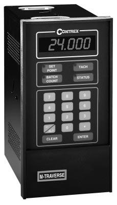
50 KEYPAD OPERATION The front panel of the M Traverse is an easy to use keypad that gives you direct access to the Parameters (Control Parameters and Monitor Variables) by entering the Parameter Code. You can also use the keypad to change the value of a Control Parameter. The keypad has keys for Code Select, Enter and Clear. It also has numeric keys and four dedicated keys: Setpoint, Tach, Status and Batch Count. The LED display is the above the keys. Refer to figure 3-1 for the location of the keys and LED display on the keypad. Table 3-1 demonstrates basic keypad entry. The keypad functions as follows: Code Select Numeric Use the Code Select key prior to entering a Parameter Code for either a Control Parameter (CP) or Monitor Variable (MV). Use the numeric keys to enter a Parameter Code for either a Control Parameter (CP) or a Monitor Variable (MV) or to enter a value for a Control Parameter. Use the Clear key to delete your entry. Use the Enter key after each entry, to enter it in the M-Traverse. /Alt Use the /Alt key to enter a negative value. In MVs 43, 44, 80, 81 and 84, the /Alt key toggles between four lower and four higher digits because some numbers exceed the six digit display panel limit.. Use the decimal key for values with a decimal point. Clear Tach Setpoint The Clear key will delete the entry, if you have not used the Enter key. The Tach key is a dedicated or shortcut key. You can access the tach Parameters directly, rather than manually entering the Parameter Code (MV-40). The Setpoint Key is a dedicated or shortcut key. You can directly access the active setpoint in the Follower mode (either CP-01, CP-03, CP-05 or CP-07) or the active setpoint in the Direct mode (CP-62). 3-3
51 Batch Count Key Status Key Lower LED Display Upper LED Display Discrete LED Display The Batch Count Key is a dedicated or shortcut key. You can directly access the Batch Count parameter (MV-89). The Status Key is a dedicated or shortcut key. You can directly access the Alarm Status parameter (MV-51). The two-digit Parameter Code is displayed on the Lower LED Display. The Parameter Code's value is displayed on the Upper LED display. This value can be up to six digits. There are five discrete LED display lights. When a specific light is on, it indicates the following condition: Run... The M-Traverse is in Follower mode and is executing a profile. Wait... The Wait input (J4 pin 8 ) is active. Drive Enable... The Drive Enable output (J1 pin 13) is active. At-Home... The Follower position is within the At-Home band of the Home position. Alarm... There is an active alarm condition. Table 3-1 Basic Keypad Entry To Enter a Parameter Code: To Enter a Parameter Value: (For Control Parameters only - Monitor Variables can not be changed manually) To Use the Tach Key: To Use the Status Key: To Use the Setpoint Key: To Use the Batch Count Key: Press Code Select. Enter a Parameter Code (For a Control Parameter or Monitor Variable). Press Enter (within 15 seconds). The Parameter Code and its current value are displayed on the LED displays. Follow the steps to enter a Parameter Code. Enter a new value (Use the numeric keys). Press Enter (within 15 seconds). Press Tach. The scaled Tach - Velocity is displayed (MV-40). Press Status. The code for the alarm status is displayed (MV-51). Press Setpoint. The value of the active setpoint is displayed, in engineering units. (CP-01, CP-03, CP-05, CP-07 or CP-62). Press Batch Count. The number of complete batch counts is displayed (MV-89). 3-4
52 Upper LED Display C ONTREX Parameter Value (up to 6 digits) Setpoint Key Set Point Tach Tach Key Batch Count Key Batch Count Status Status Key Numeric Keys /Alt Key Decimal Key Clear Key Discrete LED Indicator Display Alt Clear 0 Run Wait Drive Enbl At-Home Alarm Enter Code Select Enter Key Lower LED Display Parameter Code (2 digits) Code Select Key Figure 3-1 The M Traverse Front Panel 3-5
53 3-6
54 CONTROL PARAMETERS Parameters are divided into two classifications; Control Parameters (CP) and Monitor Variable (MV). The numbered code that represents the parameter is the Parameter Code. The operational data is the parameter's value. Parameters = Control Parameter 14 = 1 Monitor Variable 40 = 200 Parameter Code Parameter Value This section is about Control Parameters. Monitor Variables are explained in Operation: Monitor Parameters. The M Traverse comes factory pre-loaded with a complete set of default Control Parameters values. The majority of these default settings are suitable for most applications and do not require modification. Control Parameters allow you to enter data that is unique to your system (e.g., encoder resolution, Lead to Follower ratios) and modify the M Traverse for your specific needs (e.g., maximum RPM, setpoints, acceleration/deceleration ramp rates) by entering a parameter value. Control Parameters can be "locked out" so that they become inaccessible from the Keypad. For details, refer to References: Appendix C, CP-79. The M Traverse is designed to execute either the Direct mode of operation or the Follower mode of operation. The values that you enter in the relevant Control Parameters determine which of the modes of operation your M Traverse is set up for. The mode of operation that you use is determined by your systems operational requirements. The following sections demonstrate how to enter Control Parameters for the Direct mode or the Follower mode of operation. In addition, Control Parameters for Jog, Tuning and Output Control are addressed. 3-7
55 FOLLOWER MODE The M-Traverse is a multi-motor operation that is specifically designed for the precise control of reciprocating lead/follower motion control applications. Its primary mode of operation is the Follower mode. This section discusses the set up procedures for the Follower mode of operation. Refer to Introduction: Examples of M-Traverse Applications for an example of the Follower Mode. Refer to Operation: M Traverse Operation for instructions on the operation of the Follower mode. Caution: To avoid damage to your system, the M-Traverse must be calibrated and the motor drive set up before you enter the Follower mode. Refer to Installation/ Setup: Calibration. In order to set up the M-Traverse for the Follower mode of operation, Control Parameters must be entered for the following procedures: Control Mode Parameter Follower Scaling Parameters Preset Parameters Follower Profile Parameters Other Follower Parameters 3-8
56 Control Mode Parameter The Control Mode (CP-14) parameter allows you to choose between either the Standard (1) or Lay Adjusted (3) option in the Follower mode of operation. Both options will operate your system. The calculation of the Follower profile length is the only difference between the Standard and the Lay Adjusted option. In the lay adjusted option, one lay pitch is subtracted from the profile length to adjust for the initial lay on the reel. NOTE: You can also use Control Mode (CP-14) to choose the Direct mode of operation, which is used for calibration and trouble shooting. Refer to Operation: Direct Mode for information on the Direct mode. The factory default for the Control Mode Control Parameter is found in Table 3-2. To modify the default parameter refer to Table 3-3. If you are uncertain how to enter a Control Parameter, review the Operations: Keypad section. Table 3-2 Default Control Mode Control Parameter CP Parameter Name Parameter Value CP-14 Control Mode 1 (Follower /Standard) Table 3-3 Entering Control Mode Control Parameters CP Parameter Name Parameter Value CP-14 Control Mode Enter 1 to enable the Follower Mode / Standard Enter 3 to enable the Follower Mode / Lay Adjusted 3-9
57 Follower Scaling Parameters The M-Traverse allows you to use Engineering Units (e.g., feet, inches) to control and monitor your system. Follower Scaling is a convenient method for converting encoder lines to Engineering Units. Scaling Control Parameters give the M-Traverse the following information: Engineering Units (CP-15) In a level wind application, CP-15 is your Engineering Unit (E.U.) measurement of a laypitch. In a web scanning application, CP-15 is your E.U. measurement for a traverse length. If your application uses the M-Traverse's setpoint flexibility to change over the operation, and you have more than one measurement, then pick one arbitrarily. However, be sure to reference that same measurement consistently throughout the scaling set up. In setting up the scaling, you are simply allowing the M-Traverse to establish a conversion of encoder lines to the E.U. that you prefer to use. Place the decimal in the location of your desired resolution (to the tens, hundreds or thousands place). All of the other Control Parameters or Monitor Parameters that display in E.U.s will automatically display the correct decimal position. Lead PPR Reel (CP-16) In a level wind application, CP-16 is the number of Lead encoder lines that the Lead Frequency input registers as a result of one revolution of the reel. In a web scanning application, CP-16 is the number of Lead encoder lines that the Lead Frequency input registers when the Follower travels one traverse length. When you calculate this variable, be sure to consider all gear reductions, belt reductions and other types of reducers. Use the following procedure to check CP-16: Place the M-Traverse in F-Stop. Activate the Home Set input (clears the Lead position to zero). Place the M-Traverse in F-Stop. Display MV-43 (Lead Position). Move the Lead either one revolution of the reel (level wind) or one traverse length (web scan). MV-43 should have the same value as CP-16. Follower Lines per Engineering Units (CP-17) In a level wind application, CP-17 is the number of Follower encoder lines that the Feedback Frequency input registers as a result of the Follower laypitch that was entered in CP-15. In a web scanning application, 3-10
58 CP-17 is the number of Follower encoder lines that the Feedback Frequency input registers when the Follower travels one traverse length. When you calculate this variable, be sure to consider all gear reductions, belt reductions and other types of reducers. Use the following procedure to check or find CP-17 : Place the M-Traverse in F-Stop. Activate the Home Set input (clears the Follower position to zero). Place the M-Traverse in F-Stop. Display MV-44 (Follower Position). Jog the Follower either one laypitch (CP-15) for level wind or one traverse length( CP-15) for web scan. MV-44 should have the same value as CP-17. PPR Follower (CP-18) The PPR Follower (CP-18) parameter is the number of pulses per revolution of the feedback encoder (encoder resolution in lines). Maximum RPM Follower (CP-19) The Maximum RPM Follower (CP-19) parameter is the RPM of the feedback encoder shaft when the Follower is operating at maximum speed. Although this entry does not need to be exact, highly inaccurate entries will make it difficult to tune the M-Traverse for precision Follower profiling. When you calculate this variable, be sure to consider all gear reductions, belt reductions and other types of reducers. The factory defaults for the Follower Scaling Control Parameters are found in Table 3-4. To modify the default parameters refer to Table 3-5. If you are uncertain how to enter a Control Parameter, review the Operations: Keypad section. Table 3-4 Default Follower Scaling Control Parameters CP Parameter Name Parameter Value CP-15 Engineering Units CP-16 Lead PPR Reel 1000 CP-17 Follower Lines/E.U CP-18 PPR Follower (Feedback) 60 CP-19 Max RPM Follower
59 Table 3-5 Entering Follower Scaling Control Parameters CP Parameter Name Parameter Value CP-15 Engineering Units In a level wind application, enter your E.U. measurement of one laypitch. In a web scanning operation, enter your E.U. measurement for one traverse length. CP-16 Lead PPR Reel In a level wind application, enter the number of Lead encoder lines that the Lead Frequency input registers as a result of one revolution of the reel. In a web scanning application, enter the number of Lead encoder lines that the Lead Frequency input registers as a result of one traverse length. Include calculations for all gear reductions, belt reductions and other types of reducers. CP-17 Follower Lines/E.U. In a level wind application, enter the number of Follower encoder lines that the Feedback Frequency input registers as a result of one Follower laypitch (reference CP-15). In a web scanning application, enter the number of Follower encoder lines that the Feedback Frequency input registers when the Follower travels one traverse length. Include calculations for all gear reductions, belt reductions and other types of reducers. CP-18 PPR Follower (fdbk) Enter the number of pulses per revolution of the feedback encoder (encoder resolution in lines). CP-19 Max RPM Follower Enter the RPM of the feedback encoder shaft when the Follower is operating at maximum speed. Include calculations for all gear reductions, belt reductions and other types of reducers. 3-12
60 Preset Parameters Setpoints (CP-01, CP-03, CP-05, CP-07) The Setpoint parameters are set up as pairs in conjunction with the Traverse Length parameters. There are four pairs of Setpoint and Traverse Length parameters. The Setpoint value is entered in Engineering Units (E.U.s) and automatically displays the decimal position that was entered in the Engineering Units (CP-15). The Setpoint parameter determines how far the Follower travels based on the Lead. The Follower travels the setpoint distance while the Lead travels the distance entered into CP-17. In the level wind application, the Setpoint parameters are the laypitch (center-to-center distance between windings on the reel). In the web scanning application, the Setpoint parameters are the traverse length. These preset parameters can be switch selected (via the Setpoint Select switches) which gives the operator the option of changing over the product up to four times. The factory defaults for the Default Setpoint Control Parameters are found in Table 3-6. To modify the default parameters refer to Table 3-7. If you are uncertain how to enter a Control Parameter, review the Operations: Keypad section. Table 3-6 Default Setpoint Control Parameters CP Parameter Name Parameter Value CP-01 Setpoint CP-03 Setpoint CP-05 Setpoint CP-07 Setpoint
Vorne Industries. 87/719 Analog Input Module User's Manual Industrial Drive Itasca, IL (630) Telefax (630)
 Telefax (630)") Vorne Industries 87/719 Analog Input Module User's Manual 1445 Industrial Drive Itasca, IL 60143-1849 (630) 875-3600 Telefax (630) 875-3609 . 3 Chapter 1 Introduction... 1.1 Accessing Wiring Connections
Vorne Industries 87/719 Analog Input Module User's Manual 1445 Industrial Drive Itasca, IL 60143-1849 (630) 875-3600 Telefax (630) 875-3609 . 3 Chapter 1 Introduction... 1.1 Accessing Wiring Connections
Figure 1: Standard 906 Sensor and Pulser Disc. Figure 2: Standard 906 Sensor and Pulser Wrap
 Description: The TR5000 is a Full Logic Control Process ratemeter that can display up to three separate values of rate and compare them to programmable set points. Rates A & B can be programmed by the
ED3. Digital Encoder Display Page 1 of 13. Description. Mechanical Drawing. Features
 Description Page 1 of 13 The ED3 is an LCD readout that serves as a position indicator or tachometer. The ED3 can display: Speed or position of a quadrature output incremental encoder Absolute position
SCALE & WEIGHT DISPLAYS
 The MICRO SERIES SCALE & WEIGHT DISPLAYS LARGE DIGIT MODELS Mighty-5S DPM MODELS Micro-S & Mighty-1S Mighty-1S Micro-S ELECTRO-NUMERICS, INC. Introduction The Electro-Numerics family of Digital Panel Meters
UNIVERSAL DIGITAL METER DC Volts and Amps AC RMS Volts and Amps Thermocouples and RTDs Process Signals Strain Gauge and Load Cell
 99 Washington Street Melrose, MA 02176 Fax 781-665-0780 TestEquipmentDepot.com UNIVERSAL DIGITAL METER DC Volts and Amps AC RMS Volts and Amps Thermocouples and RTDs Process Signals Strain Gauge and Load
GRT SERIES INSTALLATION & OPERATING INSTRUCTIONS
 GRT SERIES INSTALLATION & OPERATING INSTRUCTIONS 99880 05/14/03 ! SAFETY INSTRUCTIONS The following instructions must be observed. This instrument was designed and is checked in accordance with regulations
User Guide UD51. Second encoder small option module for Unidrive. Part Number: Issue Number: 5.
 EF User Guide UD51 Second encoder small option module for Unidrive Part Number: 0460-0084-05 Issue Number: 5 www.controltechniques.com Safety Information The option card and its associated drive are intended
Electronic Lineshaft With Alignment F7 Drive Software Technical Manual
 Electronic Lineshaft With Alignment F7 Drive Software Technical Manual Software Number: VSF11005X, Drive Models: CIMR-F7UXXXXXX-064, CIMR-F7UXXXXXX-065 Document Number: TM.F7SW.064, Date: 02/25/2010, Rev:
For applications from 0.25 to 5 HP, the MD60 is a simple AC Microdrive that can be panel mounted as well as wall or machine mounted.
 For applications from 0.25 to 5 HP, the MD60 is a simple AC Microdrive that can be panel mounted as well as wall or machine mounted. N223 Reliance Electric s MD60 AC Drive is ready to operate out-of-the-box!
TABLE OF CONTENTS SPECIFICATIONS...1 MOUNTING...3 WIRING...4 THEORY OF OPERATION...6 MILIVOLT INPUT OPTION JUMPER SELECTIONS...7
 TABLE OF CONTENTS SPECIFICATIONS...1 MOUNTING...3 WIRING...4 THEORY OF OPERATION...6 MILIVOLT INPUT OPTION JUMPER SELECTIONS...7 FRONT PANEL OPERATIONS...8 PROGRAMMING FLOW CHART...8 DEFINITIONS OF MENU
LAUREL ELECTRONICS, INC.
 LAUREL ELECTRONICS, INC. Laureate Digital Panel Meter for Process, Strain & Potentiometer Follower Signals Features Selectable ±0.2, ±2, ±20, ±200, ±300 & ±600 Vdc voltage ranges Selectable ±2, ±20, ±200
PCM-22 Rotary Knife Controller Operators Manual
 PCM-22 Rotary Knife Controller Operators Manual Information furnished by EMERSON EMC is believed to be accurate and reliable. However, no responsibility is assumed by EMERSON EMC for its use. EMERSON EMC
Description. Specifications and Ordering Information 1900/27 Vibration Monitor
 R Specifications and Ordering Information 1900/27 Vibration Monitor Description The 1900/27 is a single-channel, stand-alone, locally mounted vibration monitor. It can be used as a stand-alone machinery
AK-PVE4 Operating Instructions. Measuring of norm signals in wall-type units. Performance:
 AK-PVE4 Operating Instructions Measuring of norm signals in wall-type units 1 2 P Performance: Digit heights: 20 mm Colour: red Display range: -999 9999 Wall-type housing: light grey made of ABS-plastic
Digital Ratio Controller
 Digital Ratio Controller RSC-406 Control Panel USER S MANUAL RATIO CONTROLLER SPEED RUN PRG ERR RATIO % CH RSC-406 Prelude Thank you for applying our RSC-406 Ratio Controller (abb.406) to you machinery
Panel cutout required: 1.772" x 3.622" (45mm x 92mm) 1.76" (45mm) 2.45" (62mm) 3.20" (81mm) 3.60" (91mm) 0.59" (15mm) Special Features
 1.76 (45mm) 2.45 (62mm) 3.20 (81mm) 3.60 (91mm) 0.59 (15mm) Special Features") NEMA4X, IP65 Front Bezel Meter with Relays Option RELAY2 RELAY1 24V OUT POWER 4 3 2 1 6 5 2 1 2 1 NO NC COM NO NC COM RTD TC P P RTD 3 4 1 2 5 TC 6 SWITCH Rear View Gasket APM765 Panel Meter Description
NEMA4X, IP65 Front Bezel Meter with Relays Option RELAY2 RELAY1 24V OUT POWER 4 3 2 1 6 5 2 1 2 1 NO NC COM NO NC COM RTD TC P P RTD 3 4 1 2 5 TC 6 SWITCH Rear View Gasket APM765 Panel Meter Description
DCP100 Digital Control Programmer Specifications
 DCP100 Digital Control Programmer Specifications EN01-6028 October 1996 Overview The DCP100 is a microprocessor based 1 /4 DIN programmer/controller for process variable versus time control of temperature,
AES-402 Automatic Digital Audio Switcher/DA/Digital to Analog Converter
 Broadcast Devices, Inc. AES-402 Automatic Digital Audio Switcher/DA/Digital to Analog Converter Technical Reference Manual Broadcast Devices, Inc. Tel. (914) 737-5032 Fax. (914) 736-6916 World Wide Web:
Rotary Knife Controller
 PCM-22 Rotary Knife Controller Information furnished by EMERSON Motion Control is believed to be accurate and reliable. However, no responsibility is assumed by EMERSON Motion Control for its use. EMERSON
(Cat. No IJ, -IK)
") (Cat. No. 1771-IJ, -IK) Product Data The Encoder/Counter Module Assembly (cat. no. 1771-IJ or 1771-IK) maintains a count, independent of the processor, of input pulses that may typically originate from
(Cat. No. 1771-IJ, -IK) Product Data The Encoder/Counter Module Assembly (cat. no. 1771-IJ or 1771-IK) maintains a count, independent of the processor, of input pulses that may typically originate from
CT340 and CT641. High Performance Low Cost Controller for Rotating Cutters and Printing Rolls. Operating Instructions
 CT340 and CT641 High Performance Low Cost Controller for Rotating Cutters and Printing Rolls Precision controller for Rotating Cutters and Printing Rolls Easy parameter setting and immediately ready to
LAUREL. Laureate Digital Panel Meter for Load Cell & Microvolt Input ELECTRONICS, INC. Features. Description
 Description LAUREL ELECTRONICS, INC. Features Laureate Digital Panel Meter for Load Cell & Microvolt Input 20, 50, 100, 250 & 500 mv ranges Span adjust from 0 to ±99,999, zero adjust from -99,999 to +99,999
INTRODUCTION INTRODUCTION
 INTRODUCTION INTRODUCTION This manual describes the 5740X-400/401 Strider Speed Control, and is intended to be a guide in the installation and operation of the control. This first section, the INTRODUCTION,
FS340 and FS641. High Performance Low Cost Controller for Flying Shears and Saws
 control motion interface motrona GmbH Zwischen den Wegen 32 78239 Rielasingen - Germany Tel. +49 (0)7731-9332-0 Fax +49 (0)7731-9332-30 info@motrona.com www.motrona.com FS340 and FS641 High Performance
Revision 1.2d
 Specifications subject to change without notice 0 of 16 Universal Encoder Checker Universal Encoder Checker...1 Description...2 Components...2 Encoder Checker and Adapter Connections...2 Warning: High
COMPANY. MX 9000 Process Monitor. Installation, Operating & Maintenance Manual AW-Lake Company. All rights reserved. Doc ID:MXMAN082416
 COMPANY MX 9000 Process Monitor Installation, Operating & Maintenance Manual 2016 AW-Lake Company. All rights reserved. Doc ID:MXMAN082416 1 Table of Contents Unpacking...3 Quick Guide...3 Connect to Sensor...3
AES-404 Digital Audio Switcher/DA/Digital to Analog Converter
 Broadcast Devices, Inc. AES-404 Digital Audio Switcher/DA/Digital to Analog Converter Technical Reference Manual Broadcast Devices, Inc. Tel. (914) 737-5032 Fax. (914) 736-6916 World Wide Web: www.broadcast-devices.com
THE ASTRO LINE SERIES GEMINI 5200 INSTRUCTION MANUAL
 THE ASTRO LINE SERIES GEMINI 5200 INSTRUCTION MANUAL INTRODUCTION The Gemini 5200 is another unit in a multi-purpose series of industrial control products that are field-programmable to solve multiple
SQM40/41 Actuators for air and gas dampers
 SQM40/41 Actuators for air and gas dampers Description SQM40/41 actuators are used for the positioning of flow control valves, butterfly valves, dampers or any application requiring rotary motion. The
USER GUIDE. DM Engineering Multi Station Relay Adapter (MSRA and MSRA-RM) Version DM Engineering
 Version DM Engineering") USER GUIDE DM Engineering Multi Station Relay Adapter (MSRA and MSRA-RM) Version 1.35 DM Engineering 2174 Chandler St. Camarillo, CA 91345-4611 805-987-7881 800-249-0487 www.dmengineering.com Overview:
USER GUIDE DM Engineering Multi Station Relay Adapter (MSRA and MSRA-RM) Version 1.35 DM Engineering 2174 Chandler St. Camarillo, CA 91345-4611 805-987-7881 800-249-0487 www.dmengineering.com Overview:
TUSKIN Equipment Corporation
 TUSKIN Equipment Corporation TC-101 Liquid Color Metering System Operation & Maintenance Manual Warning: Read instructions carefully before attempting to install, operate or service the Tuskin Metering
Standard signal metering in wall-mounting case
 User manual AKV-2VR4C Standard signal metering in wall-mounting case Technical features: Digit height: 20 mm Colour: red Range of display: -999 9999 Wall-mounting case: black, made of ABS-plastic Protection
Model 1476-C SuperQuad HR
 Model 1476-C SuperQuad HR Installation and Operating Instructions Table of Contents Page Table of Content... 2 System Description... 3 Features... 3 Installation... 4 Internal Setups... 4 Connections...
LE-650s Instruction Manual
 LE-650s Instruction Manual LE-650s Controller The LE-650s Controller is a user-friendly panel mounted operator interface for Servo Motor Rotary Cutting machines. Everything required to provide correct
Part No. ENC-LAB01 Users Manual Introduction EncoderLAB
 PCA Incremental Encoder Laboratory For Testing and Simulating Incremental Encoder signals Part No. ENC-LAB01 Users Manual The Encoder Laboratory combines into the one housing and updates two separate encoder
Special Applications Modules
 (IC697HSC700) datasheet Features 59 1 IC697HSC700 a45425 Single slot module Five selectable counter types 12 single-ended or differential inputs TTL, Non-TTL and Magnetic Pickup input thresholds Four positive
Micro-DCI 53ML5100 Manual Loader
 Micro-DCI 53ML5100 Manual Loader Two process variable inputs Two manually controlled current outputs Multiple Display Formats: Dual Channel Manual Loader, Single Channel Manual Loader, Manual Loader with
MASTR II BASE STATION 12/24V POWER SUPPLY 19A149979P1-120 VOLT/60 Hz 19A149979P2-230 VOLT/50 Hz
 Mobile Communications MASTR II BASE STATION 12/24V POWER SUPPLY 19A149979P1-120 VOLT/60 Hz 19A149979P2-230 VOLT/50 Hz CAUTION THESE SERVICING INSTRUCTIONS ARE FOR USE BY QUALI- FIED PERSONNEL ONLY. TO
Single Axis Position Controller
 SERIES P9511 Single Axis Position Controller Compact Construction Simple Go-to operation Integrated Relay Output Integrated Mains Power Supply ELEKTRO-TRADING sp. Z o.o. 44-109 Gliwice, ul. Mechaników
Self Excited Automatic Voltage Regulator For Generator Compatible with Marathon SE350* Operation Manual
 Self Excited Automatic Voltage Regulator For Generator Compatible with Marathon SE350* Operation Manual s * Use for reference purpose only and not a genuine Marathon product. 1. INTRODUCTION Sensing Input
Noise Detector ND-1 Operating Manual
 Noise Detector ND-1 Operating Manual SPECTRADYNAMICS, INC 1849 Cherry St. Unit 2 Louisville, CO 80027 Phone: (303) 665-1852 Fax: (303) 604-6088 Table of Contents ND-1 Description...... 3 Safety and Preparation
Veeder-Root brand Series C628 Dual Preset Counter (C628-8XXX) Technical Manual
 Technical Manual") Introduction Your Veeder-Root brand C628 Dual Preset Counter is one model in a family of 1/8 DIN units which offers breakthrough display technology as well as easy-to-program single-line parameters. Designed
Introduction Your Veeder-Root brand C628 Dual Preset Counter is one model in a family of 1/8 DIN units which offers breakthrough display technology as well as easy-to-program single-line parameters. Designed
R1MS-GH3 BEFORE USE... POINTS OF CAUTION INSTRUCTION MANUAL THERMOCOUPLE & DC INPUT MODULE MODEL. (8 points; isolated)
") INSTRUCTION MANUAL THERMOCOUPLE & INPUT MODULE (8 points; isolated) MODEL BEFORE USE... Thank you for choosing M-System. Before use, please check contents of the package you received as outlined below.
INSTRUCTION MANUAL THERMOCOUPLE & INPUT MODULE (8 points; isolated) MODEL BEFORE USE... Thank you for choosing M-System. Before use, please check contents of the package you received as outlined below.
BOSTON GEAR CONTROLLERS. ACE 10 Series 1/4 through 3 HP Adjustable Frequency AC Motor Controllers MEX (55) QRO (442)
 QRO (442)") BOSTON GEAR CONTROLLERS ACE 10 Series 1/4 through 3 HP Adjustable Frequency AC Motor Controllers ACE 10 Series Noted for exceptionally low motor noise, high starting torque and cool operation in a compact
BOSTON GEAR CONTROLLERS ACE 10 Series 1/4 through 3 HP Adjustable Frequency AC Motor Controllers ACE 10 Series Noted for exceptionally low motor noise, high starting torque and cool operation in a compact
EA350. Generator Automatic Voltage Regulator Operation Manual
 Generator Automatic Voltage Regulator Operation Manual Self Excited Automatic Voltage Regulator For General Generators Compatible with Marathon SE350* * Use for reference purpose only and not a genuine
C200H-AD002/DA002 Analog I/O Units Operation Guide
 C200H-AD002/DA002 Analog I/O Units Operation Guide Revised September 1995 Notice: OMRON products are manufactured for use according to proper procedures by a qualified operator and only for the purposes
263 Series LED Bargraph Indicator and Controllers
 263 Series LED Bargraph Process Control Water Treatment High resolution 51 segment LED Bargraph for easy reading Accuracy 1% Red display Vertical or Horizontal mounting & stackable Connection Diagrams
SPECIFICATION NO Model 207 Automatic GTAW Welding System
 1.0 Introduction The Model 207 is a completely self-contained Gas Tungsten Arc Welding (GTAW) System requiring only input power, inert gas and AMI Welding Head (or manual torch) for operation. Its small
AF-300 E11 Adjustable Frequency Drive
 AF-300 E11 Adjustable Frequency Drive The AF-300 E11 adjustable frequency drive is GE s new generation of micro drives. GE recognized your need for a high-performance, full-featured compact drive and designed
MICROMASTER Encoder Module
 MICROMASTER Encoder Module Operating Instructions Issue 01/02 User Documentation Foreword Issue 01/02 1 Foreword Qualified Personnel For the purpose of this Instruction Manual and product labels, a Qualified
EZCOM-1. PLC - to - AMS MESSAGE DISPLAY INTERFACE INSTALLATION AND OPERATING INSTRUCTIONS. Rev March, 2001
 EZCOM-1 PLC - to - AMS MESSAGE DISPLAY INTERFACE INSTALLATION AND OPERATING INSTRUCTIONS Rev 1.3 - March, 2001 CONTENTS Page INTRODUCTION 1 SPECIFICATIONS 1 LIST OF SUPPLIED ITEMS 1 INSTALLATION & TESTING
SPECIAL SPECIFICATION 6735 Video Optical Transceiver
 2004 Specifications CSJ 0924-06-244 SPECIAL SPECIFICATION 6735 Video Optical Transceiver 1. Description. This Item governs the furnishing and installation of Video optical transceiver (VOTR) in field location(s)
Operating Instructions
 CNTX Contrast sensor Operating Instructions CAUTIONS AND WARNINGS SET-UP DISTANCE ADJUSTMENT: As a general rule, the sensor should be fixed at a 15 to 20 angle from directly perpendicular to the target
EZ Encoder : Optical Incremental (P Series)
") 1. Introduction Our EZ Encoders effectively eliminate multiple encoder part numbers by bringing intelligence and security to the design. A four-digit LED display with two push-buttons enables the user
1. Introduction Our EZ Encoders effectively eliminate multiple encoder part numbers by bringing intelligence and security to the design. A four-digit LED display with two push-buttons enables the user
Electronic Panel Meters DIGEM Preference Program Process control, automation & laboratory uses Class 0.01 to 1 Current, Voltage, Frequency,
 Electronic Panel Meters DIGEM Preference Program Process control, automation & laboratory uses Class 0.01 to 1 Current, Voltage, Frequency, Temperature, RPM, Pressure, etc. LED/ LCD displays 1999 to 99999
General Wiring and Installation Guidelines. Typical Mounting Installations Electrical Connections General Guidelines Common Questions & Answers
 General Wiring and Installation Guidelines Typical Mounting Installations Electrical Connections General Guidelines Common Questions & Answers Congratulations on your purchase of a Dynapar brand encoder.
THE ASTRO LINE SERIES GEMINI 4000 INSTRUCTION MANUAL
 THE ASTRO LINE SERIES GEMINI 4000 INSTRUCTION MANUAL INTRODUCTION The Gemini 4100 and 4200 are both units in a multi-purpose series of industrial control units that are field-programmable to solve multiple
EA63-7D. Generator Automatic Voltage Regulator Operation Manual. Self Excited Automatic Voltage Regulator
 EA63-7D Generator Automatic Voltage Regulator Operation Manual Self Excited Automatic Voltage Regulator SP POWERWORLD LTD Willows, Waterside, Ryhall, Stamford, Lincs, PE9 4EY, UK Tel: +44 1780 756872 -
ImproX (TRT) Twin Remote Terminal INSTALLATION MANUAL
 Twin Remote Terminal INSTALLATION MANUAL") SPECIFICATIONS MODEL NUMBER: XRT910-0-0-GB-XX XRT911-0-0-GB-XX XTT911-0-0-NN-XX IMPROX TRT ImproX (TRT) Twin Remote Terminal INSTALLATION MANUAL Working Environment XRT910-0-0-GB-XX... (Aluminium Extruded
SPECIFICATIONS MODEL NUMBER: XRT910-0-0-GB-XX XRT911-0-0-GB-XX XTT911-0-0-NN-XX IMPROX TRT ImproX (TRT) Twin Remote Terminal INSTALLATION MANUAL Working Environment XRT910-0-0-GB-XX... (Aluminium Extruded
PSM-003. Micro Polarization Controller/Scrambler. User Guide
 PSM-003 Micro Polarization Controller/Scrambler User Guide Version: 1.0 Date: August 23, 2012 General Photonics, Incorporated is located in Chino California. For more information visit the company's website
Telemetry Receiver Installation Guide
 BBV Telemetry Receiver Installation Guide Models covered Rx200 Building Block Video Ltd., Unit 1, Avocet Way, Diplocks Industrial Estate, Hailsham, East Sussex, UK. Tel: +44 (0)1323 842727 Fax: +44 (0)1323
Preset counters, electronic
 The multifunction preset counters Codix 923 / 924 can be used universally. These preset pulse counters, tachometers or preset timers with up to 6 presets can solve a wide variety of control and monitoring
MG-XV operating instruction. Measuring of norm signals, 4-8-digit. Panel instrument type MG-BV Construction instrument type MG-AV
 MG-XV operating instruction Measuring of norm signals, 4-8-digit Panel instrument type MG-BV Construction instrument type MG-AV Contents 1. Brief description... 3 2. Safety instructions... 3 2.1. Proper
EA402 SERIES ANALOG INPUT FLOW RATEMETER/TOTALIZER INSTALLATION & OPERATING INSTRUCTIONS West Stetson Avenue Hemet, CA USA
 EA402 SERIES ANALOG INPUT FLOW RATEMETER/TOTALIZER INSTALLATION & OPERATING INSTRUCTIONS 3255 West Stetson Avenue Hemet, CA 92545-7799 USA Lit# 24508-68 99775 Rev. 1.1 02/25/05 Tel: 951-652-6811 Fax: 951-652-3078
DIN-1DIMU4. DIN Rail Universal Dimmer, 1 feed, 4 channels
 The is a 4-channel universal lighting control module designed to support dimming of both forward and reverse phase type loads. A single model supports both 120 and 220-240 Volt electronic and magnetic
16 Stage Bi-Directional LED Sequencer
 16 Stage Bi-Directional LED Sequencer The bi-directional sequencer uses a 4 bit binary up/down counter (CD4516) and two "1 of 8 line decoders" (74HC138 or 74HCT138) to generate the popular "Night Rider"
UDC100 Universal Digital Controller. Specification. Overview. Features. Features, continued /99 Page 1 of 4
 UDC100 Universal Digital Controller 51-52-03-29 11/99 Page 1 of 4 Specification Overview The UDC100 Universal Digital Controller is a microprocessor-based 1/4 DIN low cost temperature controller. It combines
EM1. Transmissive Optical Encoder Module Page 1 of 8. Description. Features
 Description Page 1 of 8 The EM1 is a transmissive optical encoder module. This module is designed to detect rotary or linear position when used together with a codewheel or linear strip. The EM1 consists
Installation Operation Maintenance
 Installation Operation Maintenance Rooftop Energy Recovery Module for TKD / TKH / WKD / WKH YKD / YKH / DKD / DKH # 125-155-175-200 250 265-290-340 # 275-300-350-400-500-600 April 2011 RT-SVX42B-E4 General
K3NX Process Meter OPERATION MANUAL
 Cat.No. N90 E1 1 K3NX Process Meter OPERATION MANUAL K3NX Process Meter Operation Manual Produced January 1998 Notice: OMRON products are manufactured for use according to proper procedures by a qualified
Intelligent Security and Fire Ltd
 User Manual Product ranges covered by this manual Vi-P14 Vi-P14A Document Reference Date Firmware Vi-Q4C1 Viq601a.doc 26/11/2009 From Viq001a21 Videoswitch Telephone 01252-851510 Ocean House, Redfields
General Description. Specifications. 2.1 Electrical
 Instruction Manual Models EPN020-000 EPR020-000 EPN040-000 EPR040-000 EPN060-000 EPR060-000 EPN075-000 EPR075-000 EPN100-000 EPR100-000 EPN125-000 EPR125-000 EPN150-000 EPR150-000 EPN200-000 EPR200-000
THE ASTRO LINE SERIES GEMINI 1000/2000 INSTRUCTION MANUAL
 THE ASTRO LINE SERIES GEMINI 1000/2000 INSTRUCTION MANUAL INTRODUCTION The Gemini 1000 and 2000 are both units in a multi-purpose series of industrial control units that are field-programmable to solve
SPECIFICATION NO NOTE
 NOTE The Model 207-1 is a special version of the standard M-207 Power Supply. It has been altered for a special applications requiring low current operation at high arc voltages in ambient and pressurized
SIGNET 5500 Flow Monitor ENGLISH
 ENGLISH 3.0901 H (6/01) English CAUTION! Remove power to unit before wiring input and connections. Follow instructions carefully to avoid personal injury. Contents 1. Power Connections 2. Compatible Sensor
Operating instructions Electronic preset counter Type series 717
 Operating instructions Electronic preset counter Type series 717 1. Description 5.98.3_gb 6-digit adding/subtracting counter with two presets Very bright 8mm high LED display Counting and preset range
MULTIDYNE INNOVATIONS IN TELEVISION TESTING & DISTRIBUTION DIGITAL VIDEO, AUDIO & DATA FIBER OPTIC MULTIPLEXER TRANSPORT SYSTEM
 MULTIDYNE INNOVATIONS IN TELEVISION TESTING & DISTRIBUTION INSTRUCTION MANUAL DVM-1000 DIGITAL VIDEO, AUDIO & DATA FIBER OPTIC MULTIPLEXER TRANSPORT SYSTEM MULTIDYNE Electronics, Inc. Innovations in Television
ORM0022 EHPC210 Universal Controller Operation Manual Revision 1. EHPC210 Universal Controller. Operation Manual
 ORM0022 EHPC210 Universal Controller Operation Manual Revision 1 EHPC210 Universal Controller Operation Manual Associated Documentation... 4 Electrical Interface... 4 Power Supply... 4 Solenoid Outputs...
Operating Instructions for Throttle Valves Using VRC Valve Positioner
 ThrottleMaster TM Operating Instructions for Throttle Valves Using VRC Valve Positioner p/n: X709116 $10.00 3/2012 Throttlemaster is a registered trademark of Vacuum Research Corporation Introduction The
COHERENCE ONE PREAMPLIFIER
 COHERENCE ONE PREAMPLIFIER OWNER S MANUAL TABLE OF CONTENTS Introduction Features Unpacking Instructions Installation Phono Cartridge Loading Basic Troubleshooting Technical Specifications Introduction
with Simulated Outputs Description Applications Features
 Innovative Solutions in Engineering Synchro to ACP/ARP Converter with Simulated Outputs Description The is a stand-alone system, which provides data format conversion of Synchro to ACP/ARP. The unit is
MBUS 10 RS232 TO MBUS LEVEL CONVERTER
 Media and protocol converters MBUS 10 RS232 TO MBUS LEVEL CONVERTER RS232 to MBus level conversion Maximum 10 MBus slaves Baud Rate: 300 to 19200 bps RS232 MBus opto isolation Over-current and short-circuit
VARIABLE SPEED USER MANUAL. Premium Efficiency Variable Speed Motor
 165 VARIABLE SPEED USER MANUAL Premium Efficiency Variable Speed Motor COPYRIGHT Copyright 2013, Regal Beloit America, Inc. Tipp City, Ohio. All rights reserved. TRADEMARKS All trademarks and registered
SPECIAL SPECIFICATION 1291 Fiber Optic Video Data Transmission Equipment
 1993 Specifications CSJ 0500-01-117 SPECIAL SPECIFICATION 1291 Fiber Optic Video Data Transmission Equipment 1. Description. This Item shall govern for the furnishing and installation of Fiber Optic Video
Process Transmitter RMA 422
 Technical Information TI 072R/24/ae Process Transmitter RMA 422 Multi-functional 1-2 channel top hat DIN rail unit with loop power supply, alarm set point monitoring, mathematics function and 1-2 analog
TeamWork Kits Installation Guide
 TX 0 RX COM +5V APARATUS US TeamWork Kits Installation Guide TeamWork 400 and TeamWork 600 Kits The TeamWork 400 and TeamWork 600 kits consist of an HDMI switcher, system controller, Cable Cubby, and cables
Sentinel I24 Digital Input and Output Configuration
 Application Bulletin: #155 Date: October 19, 2007 Sentinel I24 Digital Input and Output Configuration The Sentinel I24 can communicate with external hardware using digital inputs and outputs. There are
Motion Control G7 Drive Software Technical Manual
 Software Number: VSG13306X, Drive Models: CIMR-G7UXXXXX-117 Document Number: TM.G7SW.117, Date: 05/16/08, Rev: 08-05 Motion Control G7 Drive Software Technical Manual Contents: 1.0 Overview... 3 2.0 Changes
ADJUSTABLE SPEED DRIVES. nc1 Drive
 ADJUSTABLE SPEED DRIVES nc1 Drive Ultra-Compact Sub-Micro Drive The nc1 is a sub-micro, or nano-sized drive with a full range of features to meet the needs of nearly any user. The nc1 is designed to be
Operating Instructions
 COUNTERS CONTROLLERS ENCODERS Operating Instructions Electronic Preselection Counter Two preselections NE 216 Contents Page 1 Safety indications... 2 2 Get to know your NE 216... 4 2.1 NE216 components...
SPECIAL SPECIFICATION :1 Video (De) Mux with Data Channel
 Mux with Data Channel") 1993 Specifications CSJ 0924-06-223 SPECIAL SPECIFICATION 1160 8:1 Video (De) Mux with Data Channel 1. Description. This Item shall govern for furnishing and installing an 8 channel digital multiplexed
1993 Specifications CSJ 0924-06-223 SPECIAL SPECIFICATION 1160 8:1 Video (De) Mux with Data Channel 1. Description. This Item shall govern for furnishing and installing an 8 channel digital multiplexed
Registers type ILR7XX and ILR7XXT
 Badger Meter Europa GmbH Registers type ILR7XX and ILR7XXT INSTALLATION AND OPERATION MANUAL May 2018 Contents Page 1. Basic safety recommendations... 1 2. Register operation... 3 2.1. Normal operation...
SPECIAL SPECIFICATION 6911 Fiber Optic Video Data Transmission Equipment
 2004 Specifications CSJ 3256-02-079 & 3256-03-082 SPECIAL SPECIFICATION 6911 Fiber Optic Video Data Transmission Equipment 1. Description. Furnish and install Fiber Optic Video Data Transmission Equipment
Model 5240 Digital to Analog Key Converter Data Pack
 Model 5240 Digital to Analog Key Converter Data Pack E NSEMBLE D E S I G N S Revision 2.1 SW v2.0 This data pack provides detailed installation, configuration and operation information for the 5240 Digital
ELECTRICAL. DATA AND INDEX Not all complements shown A shown for reference. Index A leads B, CW (from shaft end) TERMINAL CONNECTIONS COM VCC CASE
 TERMINAL CONNECTIONS COM VCC CASE") NorthStar brand SERIES HD35R Heavy Duty Encoder Key Features Phased Array Sensor for Reliable Signal Output Rugged Design with Wide-Spaced Oversized Bearings Unbreakable Code Disc up to 5000PPR Improved
NorthStar brand SERIES HD35R Heavy Duty Encoder Key Features Phased Array Sensor for Reliable Signal Output Rugged Design with Wide-Spaced Oversized Bearings Unbreakable Code Disc up to 5000PPR Improved
DP1 DYNAMIC PROCESSOR MODULE OPERATING INSTRUCTIONS
 DP1 DYNAMIC PROCESSOR MODULE OPERATING INSTRUCTIONS and trouble-shooting guide LECTROSONICS, INC. Rio Rancho, NM INTRODUCTION The DP1 Dynamic Processor Module provides complete dynamic control of signals
1900/25 Vibration Monitor
 1900/25 Vibration Monitor BENTLY NEVADA MADE IN USA VIBRATION MONITOR OK ALERT DANGER BYPASS DISPLAY MOD E RESET NORMAL ALERT ALERT ADJUST LEVEL DANGER DANGER LEVEL ADJUST BUFFER ED TRANSDUCER 1 IN/SEC
Netzer AqBiSS Electric Encoders
 Netzer AqBiSS Electric Encoders AqBiSS universal fully digital interface Application Note (AN-101-00) Copyright 2003 Netzer Precision Motion Sensors Ltd. Teradion Industrial Park, POB 1359 D.N. Misgav,
CERTIFICATE of EU TYPE-EXAMINATION
 CERTIFICATE of EU TYPE-EXAMINATION No. DK 0199.187 EBW 10-xx / EBW 20-xx / Jesbelt xx CONTINUOUS TOTALISER Issued by DELTA Danish Electronics, Light & Acoustics EU - Notified Body No. 0199 In accordance
MclNTOSH MODEL C-4 and C-4P
 INSTRUCTION MANUAL MclNTOSH MODEL C-4 and C-4P AUDIO COMPENSATORS McINTOSH LABORATORY, INC. 320 Water St. Binghamton, N. Y. U.S.A. - 1 - INSTRUCTION MANUAL McINTOSH MODEL C-4 and C-4P AUDIO COMPENSATORS