XCOM1002JE (8602JE) Optical Receiver Manual
|
|
|
- Dorthy Higgins
- 6 years ago
- Views:
Transcription
")

1 XCOM1002JE (8602JE) Optical Receiver Manual
2 - 2 -
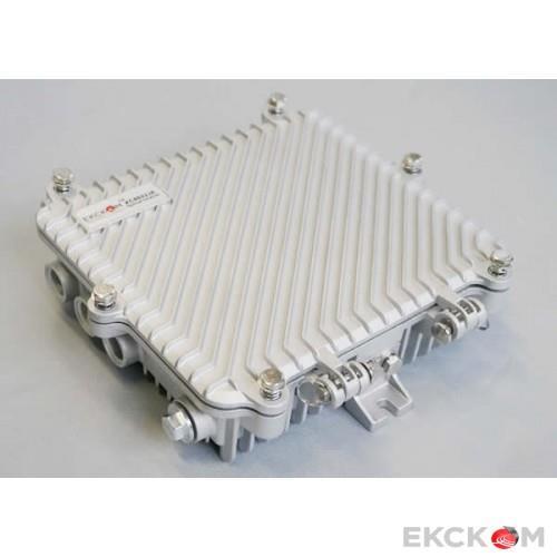
3 1. Product Summary XCOM1002JE (8602JE) outdoor optical receiver is our latest 1GHz optical receiver. With wide range receiving optical power, high output level, low power consumption and compact structure, easy to install. It is the ideal equipment to build the high-performance NGB network. 2. Performance Characteristics Adopt advanced optical AGC technique, optical AGC control range: +2dBm~-9/-8/-7dBm adjustable; Forward working frequency extended to 1GHz, RF amplifier part adopts the high performance low power consumption GaAs chip, the maximum output level up to 116 dbμv; EQ and ATT both use the professional electric control circuit, make the control more accurate, operation more convenient; Built-in the standard II class network management responder, support remote network management (optional); The optical output port and network management interface are external or internal (optional); Built-in high reliability low power consumption power supply; 3. Technique Parameter 3.1 Link testing conditions The technique parameters of this manual according to the measuring method of GY/T <Specifications and methods of measurement on optical node used in CATV systems>, and tested in the following conditions. Testing conditions: Forward optical receive part: with 10km standard optical fiber, passive optical attenuator and standard optical transmitter composed the testing link. Set 59 PAL-D analog TV channel signal at range of 45/87MHz~550MHz under the specified link loss. Transmit digital modulation signal at range of 550MHz~862/1003MHz, the digital modulation signal level (in 8 MHz bandwidth) is 10dB lower than analog signal carrier level. When the input optical power of optical receiver is -1dBm, the RF output level is 108dBμV, with 9dB output tilt, measure the C/CTB, C/CSO and C/N. Note: When the rated output level is the system full configuration and the receiving optical power is -1dBm, equipment meets the maximum output level of link index. When the system configuration reduce (that is, actual transmission channels reduce), the output level of equipment will be increased. Friendly Notice: Suggest you setting the RF signal to 6~9dB tilt output in the practical engineering application to improve the nonlinear index (under the node) of the cable system
4 3.2 Technique Parameters Item Unit Technical Parameters Optical Parameters Receiving Optical Power dbm -9 ~ +2 Optical AGC Control Range dbm +2 ~ -9/-8/-7 (adjustable) Optical Return Loss db >45 Optical Receiving Wavelength nm 1100 ~ 1600 Optical Connector Type SC/APC or specified by the user Fiber Type Single mode Link Performance C/N db 51 EQ 8dB, Output level 108 dbμv C/CTB db 67 (FZ110) C/CSO db 62 RF Parameters Frequency Range MHz 45 ~862/1003 Flatness in Band db ±0.75 Rated Output Level dbμv 108 Max Output Level dbμv 112 (-9 ~ +2dBm Optical power receiving) 116 (-7 ~ +2dBm Optical power receiving) Output Return Loss db 16 Output Impedance Ω 75 Electrical control EQ range db 0~15 Electrical control ATT range db 0~15 General Characteristics Power Voltage V A: AC(150~265)V B: AC (35~90) V Operating Temperature -40~60 Consumption VA 14 Dimension mm 220(L)* 205(W)* 65(H) Note: The forward RF indexes above are tested when adopt NEC module. Use other module, the indexes will be a little different
5 4. Block Diagram 5. Relation Table of Input Optical Power and CNR - 5 -
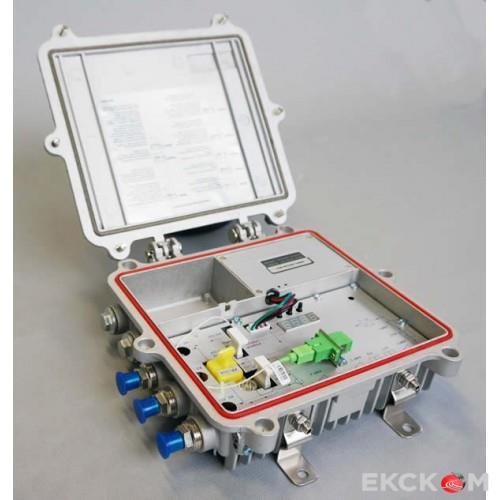
 9 AC60V power-pass inserter port 10 OUT1 11-20dB test port 12 AC60V feed port 13 FZ110 or FP204 14 AC60V power-pass")
6 6. Structure Description Working indicator 2 Optical receiving port (or 3 LED digital display tube external, optional) 4 Enter key 5 Down key 6 Up key 7 Power Interface 8 AC220V input port (when AC220V power supply) 9 AC60V power-pass inserter port 10 OUT dB test port 12 AC60V feed port 13 FZ110 or FP AC60V power-pass inserter port 15 OUT 2 16 Transponder connecting wire 17 Optical fiber access port 18 RJ45 interface (or external, optional) 19 Network cable in 20 Operating instruction 21 Switching power supply 22 Transponder - 6 -
7 7. Function Display and Operating Instruction Mode: Mode selection button, total twelve modes, press the mode selection button to enter the corresponding status display, twelve modes to cycle. The following is the detailed instructions: - 7 -

; start upper computer network management software, then search the device and log in. 3.")

8 8. NMS setup instructions If users configured the network management responder, need to do the following settings: Responder IP setup instruction: Network management directly modify: 1. Default IP is ,default gateway is ,default subnet mask is Connect the computer and responder (can be direct connected), and change the computer IP to XXX (XXX is any number from 0 to 255 except 168); start upper computer network management software, then search the device and log in. 3. Right-click device icon and choose modify the device IP. 4. Enter new IP address, gateway and subnet mask. 5. Click modify,then exit, it is done. There will show new IP address and gateway on operational logbook. 6. Reboot the responder, the new IP take effect (Click the reboot button in the network management software or power on again) - 8 -
9 9. Common Failure Analysis and Troubleshooting Failure phenomenon Failure cause Solution After connecting the network, the image of the optical contact point has obvious netlike curve or large particles highlights but the image background is clean. After connecting the network, the image of the optical contact point has obvious noises. After connecting the network, the images of several optical contact points randomly appear obvious noises or bright traces. After connecting the network, the images of several optical contact points appear one or two 1. The input optical power of the optical receiver is too high, make the output level of the optical receiver module too high and RF signal index deteriorate. 2. The RF signal (input the optical transmitter) index is poor. 1. The input optical power of the optical receiver is not high enough, results in the decrease of C/N. 2. The optical fiber active connector or adapter of the optical receiver has been polluted. 3. The RF signal level input the optical transmitter is too low, make modulation degree of the laser is not enough. 4. The C/N index of system link signal is too low. The optical contact point has open circuit signal interference or strong interference signal intrusion. Power supply AC ripple interference because of the bad earth of equipment or power supply. 1. Check the input optical power and make appropriate adjustments to make it in the specified range; or adjust the attenuation of optical receiver to reduce the output level and improve index. 2. Check the front end machine room optical transmitter RF signal index and make appropriate adjustments. 1. Check the received optical power of the optical contact point and make appropriate adjustments to make it in the specified range. 2. Recover the received optical power of the optical contact point by cleaning the optical fiber connector or adapter etc methods. Specific operation methods see Clean and maintenance method of the optical fiber active connector. 3. Check the RF signal level input the optical transmitter and adjust to the required input range. (When the input channels number less than 15, should higher than nominal value.) 4. Use a spectrum analyzer to check the system link C/N and make appropriate adjustments. Make sure the system link signal C/N>51dB. 1. Check if there is strong interference signal source; change the optical contact point location if possible to avoid the influence of strong interference signal source. 2. Check the cable lines of the optical contact point, if there is shielding net or situation that the RF connector shielding effect is not good. 3. Tightly closed the equipment enclosure to ensure the shielding effect; if possible add shielding cover to the optical contact point and reliable grounding. Check grounding situation of the equipment, make sure that every equipment in the line has been reliably grounding and the grounding resistance must be<4ω
10 horizontal bright traces. After connecting the network, the received optical power of the optical contact point is unstable and has large continuous change. The output RF signal is unstable, too. But the detected output optical power of the optical transmitter is normal. The optical fiber active connector types do not match, maybe the APC type connect to PC type, make the optical signal cannot normal transmission. The optical fiber active connector or adapter may be polluted seriously or the adapter has been damaged. 1. Check the type of optical fiber active connector and adopt the APC type optical fiber active connector to ensure the normal transmission of optical signal. 2. Clean the polluted optical fiber active connector or adapter. Specific operation methods see Clean and maintenance method of the optical fiber active connector. 3. Replace the damaged adapter. 10. Clean and maintenance method of the optical fiber active connector In many times, we misjudge the decline of the optical power or the reduce of optical receiver output level as the equipment faults, but actually it may be caused by the incorrect connection of the optical fiber connector or the optical fiber connector has been polluted by the dust or dirt. Now introduce some common clean and maintenance methods of the optical fiber active connector. 1. Carefully pull off the optical fiber active connector from the adapter. The optical fiber active connector should not aim at the human body or the naked eyes to avoid accidental injury. 2. Wash carefully with good quality lens wiping paper or medical degrease alcohol cotton. If use the medical degrease alcohol cotton, still need to wait 1~2 minutes after wash, let the connector surface dry in the air. 3. The cleaned optical fiber active connector should be connected to optical power meter to measure output optical power to affirm whether it has been cleaned up. 4. When connect the cleaned optical fiber active connector back to adapter, should notice to make the force appropriate to avoid the ceramic tube in the adapter crack. 5. If the output optical power is not normal after cleaning, should pull off the adapter and clean the other connector. If the optical power still low after cleaning, the adapter may be polluted, clean it. (Note: Be carefully when pull off the adapter to avoid hurting inside fiber.) 6. Use the dedicated compressed air or degrease alcohol cotton bar to clean the adapter. When use the compressed air, the muzzle of the compressed air tank should aims at the ceramic tube of the adapter, clean the ceramic tube with compressed air. When use degrease alcohol cotton bar, carefully insert the alcohol cotton bar into the ceramic tube to clean. The insert direction should be consistent, otherwise can not reach ideal cleaning effect
11 11. After-sales service description 1. We promise: Free warranty for thirteen months (Leave factory time on product qualification certificate as the start date). The extended warranty term based on the supply agreement. We responsible for lifetime maintenance. If the equipment fault is resulted from the users improperly operation or unavoidable environment reasons, we will responsible maintenance but ask suitable material cost. 2. When the equipment breaks down, immediately contact local distributor or directly call our technical support hotline , The site maintenance of the fault equipment must be operated by professional technicians to avoid worse damage. Special notice: If the equipment has been maintained by users, we will not responsible free maintenance. We will ask suitable maintenance cost and material cost
Optical Receiver Manual. Transmitter OP-OR212JSE. Shenzhen Optostar Optoelectronics Co., Ltd (Version 2)
") Optical Receiver Manual Transmitter OP-OR212JSE Shenzhen Optostar Optoelectronics Co., Ltd 2016. 7(Version 2) 1. Summary OP-OR212JSE optical receiver is the latest 1GHz dual-way switch optical receiver.
Optical Receiver Manual Transmitter OP-OR212JSE Shenzhen Optostar Optoelectronics Co., Ltd 2016. 7(Version 2) 1. Summary OP-OR212JSE optical receiver is the latest 1GHz dual-way switch optical receiver.
Optical Receiver Manual. Transmitter OP-OR112R JⅢ. Shenzhen Optostar Optoelectronics Co., Ltd (Version 2)
") Optical Receiver Manual Transmitter OP-OR112R JⅢ Shenzhen Optostar Optoelectronics Co., Ltd 2016. 7(Version 2) 1. Summary OP-OR112RJⅢ optical receiver is our latest 1GHz FTTB optical receiver. With wide
Optical Receiver Manual Transmitter OP-OR112R JⅢ Shenzhen Optostar Optoelectronics Co., Ltd 2016. 7(Version 2) 1. Summary OP-OR112RJⅢ optical receiver is our latest 1GHz FTTB optical receiver. With wide
Four-way Return Optical Receiver Manual. Transmitter OP-OR124RJ. Shenzhen Optostar Optoelectronics Co., Ltd (Version 1)
") Four-way Return Optical Receiver Manual Transmitter OP-OR124RJ Shenzhen Optostar Optoelectronics Co., Ltd 2016. 7(Version 1) 1. Summary OP-OR124RJ type is the upgrade product of OP-OR124R type. Can automatically
Four-way Return Optical Receiver Manual Transmitter OP-OR124RJ Shenzhen Optostar Optoelectronics Co., Ltd 2016. 7(Version 1) 1. Summary OP-OR124RJ type is the upgrade product of OP-OR124R type. Can automatically
Fiber Optic. Foreword. Special Tips:
 Foreword This manual applies to 1310nm AM direct modulated optical transmitter with SNMP network management interface. It mainly describes the performance characteristics, technical parameters, installation
FOREWORD. Special Notice:
 FOREWORD This manual is applicable to series SNMP network control port 1310nm AM direct modulation optical transmitter. Mainly expatiate the product's function characteristics, technique parameters, installation
DVO700 P FIBRE OPTIC TRANSMITTER
 Timo Rantanen September 24, 2002 1(5) FIBRE OPTIC TRANSMITTER is a high performance, extremely linear externally modulated 1550 nm transmitter for DVO fibre optic CATV link. This transmitter type has been
OTX Optical Transmitter. Operation Instructions
 OTX 1310-10 Optical Transmitter Operation Instructions Operation Instructions OTX 1310-10 Optical Transmitter Table of contents 1. Description...4 1.1. Block Diagram...4 2. Front and rear panel...5 2.1.
OPTICAL DISTRIBUTION STATION -
 optical distribution station is a high performance, four individual outputs node. With high output levels and performance to 862MHz, it provides an ideal platform for support of the evolving technologies
User Manual CXE800. Fibre Optic Receiver. CXX Series. Teleste Corporation
 Broadband Cable Networks August 30, 2007 1(8) CXX Series User Manual Teleste Corporation CXE800 Fibre Optic Receiver Broadband Cable Networks August 30, 2007 2(8) Introduction The CXE800 is a unidirectional,
User Manual CXE Rev (12) CXX Series. User Manual. Teleste Corporation CXE810. Fibre optic receiver
 CXX Series. User Manual. Teleste Corporation CXE810. Fibre optic receiver") 27.3.2012 1(12) CXX Series User Manual Teleste Corporation CXE810 Fibre optic receiver 27.3.2012 2(12) Contents Introduction... 3 Installation... 3 Housing... 3 Powering... 4 Interfaces... 4 Fibre installation...
27.3.2012 1(12) CXX Series User Manual Teleste Corporation CXE810 Fibre optic receiver 27.3.2012 2(12) Contents Introduction... 3 Installation... 3 Housing... 3 Powering... 4 Interfaces... 4 Fibre installation...
HDO701 FIBRE OPTIC TRANSMITTER
 Timo Rantanen 12.7.2011 1(5) HDO701 FIBRE OPTIC TRANSMITTER HDO701 is a high performance, extremely linear externally modulated 1550 nm transmitter for fibre optic CATV links. This transmitter type has
Compact EGC Fiber Deep Nodes A90100 and A90300
 Compact EGC Fiber Deep Nodes A90100 and A90300 The Compact EGC Fiber Deep Node (FDN) is a small node designed to meet the growing needs for network segmentation. It provides advanced features and benefits,
Multicom Optical Return Path Receiver MUL HRPR 4B
 Multicom Optical Return Path Receiver User Manual v.9 www.multicominc.com 800 423 2594 407 331 7779 1076 Florida Central Parkway, Longwood, FL 32750 SAFETY NOTIFICATION Multicom strongly advises you to
OTLT / OTLR 3000 Manual. L-Band Fiber Optic Link MHz INSTRUCTION MANUAL
 OTLT / OTLR 3000 Manual L-Band Fiber Optic Link 850-3000 MHz INSTRUCTION MANUAL Phone: (209) 586-1022 (800) 545-1022 Fax: (209) 586-1026 E-Mail: sales@olsontech.com REV. X1 www.olsontech.com 05/12/06 INSTALLATION
FiberLink 7142 Series
 MANUAL FiberLink 7142 Series 4 Channels of Composite Video and 8 Channels of Audio over one single mode or multimode fiber Installation and Operations Manual WWW.ARTEL.COM FibeLink 7142 Series Contents
Product Operation Manual
 Product Operation Manual VL-FTX FORWARD TRANSMITTER MODULE Ver 1.1(Doc#01-02-008) VALE SYSTEMS INC. 10400 Overland Road #408 Boise, ID 83709-1449,USA Tel: 208.935.6317Fax: 208.935.6234 All rights reserved
INSTALLATION MANUAL FT-FOTR-8VD-ST-S. 8-Channel Digital Duplex Baseband Video Transmitter and Receiver With Reverse Data Transmission for PTZ Cameras
 INSTALLATION MANUAL FT-FOTR-8VD-ST-S 8-Channel Digital Duplex Baseband Transmitter and Receiver With Reverse Transmission for PTZ Cameras v1.0 4/5/11 1 PACKAGE CONTENTS This package contains: One each
INSTALLATION MANUAL FT-FOTR-1VDE-ST-S
 INSTALLATION MANUAL FT-FOTR-1VDE-ST-S 1-Channel Digital Duplex Baseband Video Transmitter and Receiver With Reverse Data Transmission & Ethernet Transmission v1.0 4/5/11 1 PACKAGE CONTENTS This package
Model GS Port Node 1 GHz with 65/86 MHz split
 Model GS7000 4-Port Node 1 GHz with 65/86 MHz split The Model GS7000 4-Port Node is our latest generation 1 GHz optical node platform and utilizes a completely new housing designed for optimal heat dissipation.
Z-Light 6TX / 16TX / 26TX Intelligent Direct Modulated Optical Transmitter Operating Manual
 Z-Light 6TX / 16TX / 26TX Intelligent Direct Modulated Optical Transmitter Operating Manual Z-Band Technologies 848-B N. Hanover St., Carlisle, PA 17013 866.902.2606 www.z-band.com October 2018 (Version
Optical Communications Mainframe - Laser Transmitter Module
 About the Product The LTM13 Multi Quantum Well (MQW) Distributed Feedback (DFB) laser transmitter module has been designed for cable television and HFC broadband applications. The LTM13 module easily fits
HDBS-5000DW Series. 950MHz~2400 MHz
 SATLINK:OS-09004 3 Ver. 2.4en HDBS-5000DW Series 4 SAT-IF & 1 CATV DWDM Optical transmitter/receiver 950MHz~2400 MHz Technical Specification CONTENT 1.0 PRODUCT DESCRIPTION...1 2.0 PRODUCT FEATURE... 2
Description. Features MODEL ODN2P OPTICAL DISTRIBUTION NODE WITH TWO AMPLIFIED RF PORTS LIGHT LINK SERIES 2.
 MODEL ODN2P OPTICAL DISTRIBUTION NODE WITH TWO AMPLIFIED RF PORTS LIGHT LINK SERIES 2 Description Features The Light LinkB B Series 2 Optical distribution node with two amplified RF ports (ODN2P) has been
! "#$ ' % & % & ' ( )!' *!+, ( *-"(! './ 0 / 0/ $ 1/ 2$3 1
!' *!+, ( *-(! './ 0 / 0/ $ 1/ 2$3 1") ! "#$ ' %& %& ' ()!' *!+, (*- "(!'./0/0/ $1/2$3 1 1550 Fiber Transmitters 1550 nm External Modulation 4CHT8500AC (40~1GHz) 4CHT8500A 40~870 MHz) 1550nm External Modulation CATV Optic Transmitter Product
! "#$ ' %& %& ' ()!' *!+, (*- "(!'./0/0/ $1/2$3 1 1550 Fiber Transmitters 1550 nm External Modulation 4CHT8500AC (40~1GHz) 4CHT8500A 40~870 MHz) 1550nm External Modulation CATV Optic Transmitter Product
OMNISTAR GX2. GX2-LM1000E Series 1310 nm Broadcast Transmitter DATA SHEET BENEFITS. 1 GHz bandwidth
 DATA SHEET BENEFITS OMNISTAR GX2 GX2-LM1000E Series 1310 nm Broadcast Transmitter 1 GHz bandwidth High module density up to 16 transmitter modules in a 4 RU housing High performance: Advanced predistortion
OPTILAB CATALOG TRANSMITTER OPTICAL NODE MINI-NODE EDFA PASSIVE OPTICS RECEIVER
 OPTILAB CATALOG END-TO-END LASERS AND FIBER OPTIC PRODUCTS FOR RFOG, HFC, PON, DEEP FIBER 2013 Q3 OPTILAB CATALOG RUS & USDA ACCEPTED PRODUCTS VERSATILE AND EXCELLENT TRANSMISSION SOLUTIONS FOR HFC, RFOG,
OPERATOR MANUAL OSD8865 DIGITAL TRIPLE VIDEO FIBER OPTIC RECEIVER
 OPERATOR MANUAL OSD8865 DIGITAL TRIPLE VIDEO FIBER OPTIC RECEIVER INDEX 1 1 TECHNICAL SUMMARY... 4 1.1 BRIEF DESCRIPTION... 4 1.1.1 OVERVIEW... 4 1.1.2 APPLICATIONS... 4 1.1.3 FEATURES AND BENEFITS...
OmniStar GX2 Headend Optics Platform GX2 LM1000E Series
 arris.com OmniStar GX2 Headend Optics Platform GX2 LM1000E Series 1310 nm Broadcast Transmitter FEATURES High density optical platform with up to 16 transmitters per chassis for headend space optimization
Cisco GS7000 High-Output 4-Way Segmentable Node with 42/54 Split
 Data Sheet Cisco GS7000 High-Output 4-Way Segmentable Node with 42/54 MHz Split The Cisco GS7000 High-Output Segmentable Node with 42/54 MHz Split is the latest-generation 1-GHz optical node platform designed
1. Product Summary. 2. Features, Performance Characteristics. 3. Block Diagram
 H-RF-SWITCH 1. Product Summary An RF switch is used for signal distribution redundancy or for remote RF switching. Our RF Switch has two inputs and a single output. One of the inputs acts as the primary
FORWARD PATH TRANSMITTERS
 CHP Max FORWARD PATH TRANSMITTERS CHP Max5000 Converged Headend Platform Unlock narrowcast bandwidth for provision of advanced services Economical and full-featured versions Low profile footprint allows
CPON-HFC. Customer Premises Optical Node for FTTH networks. About the Product
 About the Product The Light Link Direct CPON-HFC customer premises optical node for FTTH networks offers full-bandwidth cable television delivery, plus broadband access via DOCSIS cable modems. Fibre-to-the-home
Typical applications:
 Typical applications: Managing multiple inputs for growing satellite teleports Extended L-band frequency for Ka-band & HTS applications Routing live traffic to multiple modems ETL s new ultra compact Hurricane
L-Band Fiber Optic Link
 One Jake Brown Road Old Bridge, NJ 08857-1000 USA (800) 523-6049 (732) 679-4000 FAX: (732) 679-4353 www.blondertongue.com INSTRUCTION MANUAL L-Band Fiber Optic Link For Direct Broadcast Satellite Distribution
OPERATOR MANUAL OSD553 TRIPLE VIDEO FIBRE OPTIC RECEIVER
 OPERATOR MANUAL OSD553 TRIPLE VIDEO FIBRE OPTIC RECEIVER OSD553 TRIPLE VIDEO FIBRE OPTIC RECEIVER Document No: 101035 Revision 02 PAGE 2 C O N T E N T S 1. TECHNICAL SUMMARY... 4 1.1 BRIEF DESCRIPTION...
ED5229GT-E Series. Page 1 of 8
 ED5229GT-E Series GPON EDFA with WDM for IP (OLT) wavelengths Multi Optical Outputs (With Pluggable Cooling fans, fan speed monitoring & alarm / for Outdoor Cabinet Environment) 1310nm Forward Optical
Emcore SITU2831 Externally Modulated RF Amplified Fiber Optic Transmitter and SIRU3000 Fiber Optic Receiver
 PRELIMINARY Applications RF and microwave antenna signal distribution EW Systems Broadband delay-line and signal processing systems Frequency distribution systems Radar system calibration Phased array
Compact Mini Amplifiers Series and Series
 RF-Electronics Compact Mini Amplifiers 93188 Series and 93198 Series Description The Scientific-Atlanta Compact Mini Amplifiers type 93188 and 93198 are small, cost-effective RF amplifiers that address
Cisco GS7000 High-Output (GaN) 4-Way Segmentable Node with 85/102 MHz Split
 4-Way Segmentable Node with 85/102 MHz Split") Data Sheet Cisco GS7000 High-Output (GaN) 4-Way Segmentable Node with 85/102 MHz Split Consumer bandwidth demand continues to grow at a rapid rate every year. As a result, cable operators with DOCSIS-based
Data Sheet Cisco GS7000 High-Output (GaN) 4-Way Segmentable Node with 85/102 MHz Split Consumer bandwidth demand continues to grow at a rapid rate every year. As a result, cable operators with DOCSIS-based
OPERATOR MANUAL OSD351 FIBRE OPTIC CCTV TRANSMITTER CARD
 OPERATOR MANUAL OSD351 FIBRE OPTIC CCTV TRANSMITTER CARD OSD351 FIBRE OPTIC CCTV TRANSMITTER CARD Document No:10103701 PAGE 2 C O N T E N T S 1. TECHNICAL SUMMARY...4 1.1 BRIEF DESCRIPTION...4 1.2 TECHNICAL
User s Manual of Signal Level Meter TABLE OF CONTENTS
 TABLE OF CONTENTS A OVERVIEW OF SIGNAL LEVEL METER...2 B FEATURES OF SIGNAL LEVEL METER...2 C PRECAUTIONS...2 D PANEL AND LCD...3 E INSTRUCTIONS OF KEYS...3 1. SINGLE-CHANNEL MEASUREMENT...4 2. SINGLE-FREQUENCY
SatellitePlus Model OLAT/OLAR. Advanced L-Band Series. 10-4,000 MHz OPERATING MANUAL
 SatellitePlus Model OLAT/OLAR Advanced L-Band Series 10-4,000 MHz OPERATING MANUAL 24926 Highway 108 Sierra Village, CA 95346 Phone: (800) 545-1022 Fax: (209 586-1022 025-000570 Rev. X7 E-Mail: sales@olsontech.com
Prisma Optical Networks Ancillary Modules
 Optoelectronics Prisma Optical Networks Ancillary Modules Description The Prisma platform is capable of utilizing a combination of modules which address a variety of revenue generating applications. The
ED5229GT-E/GTRE Series
 ED5229GT-E model ED5229GTRE model ED5229GT-E/GTRE Series GPON EDFA with WDM for IP (OLT) wavelengths Multi Optical Outputs (With Pluggable Cooling fans, fan speed monitoring & alarm / for Outdoor Cabinet
ACION 8000 Series. A8KFR1 1RU Forward Receiver
 ACION 8000 Series A8KFR1 1RU Forward Receiver Overview The A8KFR1 is an advanced Forward Optical Receiver designed for HFC network to convert the optical signal to RF signal for distribution, with high
RLT 1550 d10. DWDM High Power, Ultra Wide Band CATV & SAT MHz Laser Optical Transmitter, with pre-correction, LAN remote control and alarms
 RLT 1550 d10 DWDM High Power, Ultra Wide Band CATV & SAT 47-2.700 MHz Laser Optical Transmitter, with pre-correction, LAN remote control and alarms The ultra wide band, 47-2.700 MHz, optical, laser transmitter,
DS2460Q QAM Analysis Meter
 DS2460Q QAM Analysis Meter Key Benefits Comprehensive tool for installation and maintenance of cable networks Fast spectrum analysis, 5~1220 MHz 5~1052MHz (Analog TV), 46~1052MHz (Digital TV) Digital TV
8 Ports. 16 Ports. ED5219LGT Series. CATV Single Channel EDFA 1310nm Forward Optical Transmitter
 8 Ports 16 Ports CATV Single Channel EDFA 1310nm Forward Optical Transmitter The ACI ED5219LGT series is a high-power multi-ports EDFA optical booster with gain spectrum bandwidth from 1545 to 1563 nm
2015 OPTICAL TRANSMITTERS
 2015 OPTICAL TRANSMITTERS Released V H Mar 15 SATELLITE AND TERRESTRIAL OPTICAL BROADCAST EQUIPMENT DVB is a registered trademark of the DVB Project A DVA NCE D TECHNOLOGY FOR PROFESSIONAL BROADCASTING
HDMI Extender via Single SC Fiber Support 3D/4K2K Up To 10Km In One Single-mode Fiber
 Description HDMI (High-Definition Multimedia Interface) recently has become increasingly popular in the application of video and audio transmission system. In view of the extreme of electrical performances,
Model 755U Optical Transmitter DWDM, up to 20 km, Low Distortion, Wideband
 Model 755U Optical Transmitter DWDM, up to 20 km, Low Distortion, Wideband Emcore s Model 755U is a directly modulated (DM) DWDM optical transmitter specifically designed for wideband applications that
EPON ONU Triplexer Transceiver
 EPON ONU Triplexer Transceiver Features Single Fiber Triplexer 1.25Gbps data upstream and downstream /45~1000MHz CATV analog signal downstream Burst mode transmission with 1310nm FP laser Continuous mode
OPERATOR MANUAL OSD390 SERIES 4 CHANNEL VIDEO/AUDIO/DATA FIBER OPTIC TRANSMISSION SYSTEM
 PTY. LTD A.B.N. 83 003 020 504 OPERATOR MANUAL OSD390 SERIES 4 CHANNEL VIDEO/AUDIO/DATA FIBER OPTIC TRANSMISSION SYSTEM OSD390 SERIES 4 CHANNEL VIDEO/AUDIO/DATA FIBER OPTIC TRANSMISSION SYSTEM Document
Multicom 1550nm Optical Transmitter MUL-1550TX-1000-XX
 User Manual v.8 www.multicominc.com 800-423-2594 407-331-7779 1076 Florida Central Parkway, Longwood, FL 32750 SAFETY NOTIFICATION The Multicom 1550nm Optical Transmitter is classified as Class 1M per
H5000 Outdoor Mini Virtual HUB
 H5000 Outdoor Mini Virtual HUB The H5000 is an RFOG Indoor/Outdoor Mini Virtual Hub that provides an optical distribution point for downstream traffic and an aggregation point for upstream traffic, making
Headend Optics Platform (CH3000)
") arris.com Headend Optics Platform (CH3000) HT3540H Series Double-Density Full Spectrum DWDM Transmitter System FEATURES DWDM transmitter: up to 40 wavelengths on ITU grid Hot plug in/out, individually
arris.com Headend Optics Platform (CH3000) HT3540H Series Double-Density Full Spectrum DWDM Transmitter System FEATURES DWDM transmitter: up to 40 wavelengths on ITU grid Hot plug in/out, individually
MIGRATION TO FULL DIGITAL CHANNEL LOADING ON A CABLE SYSTEM. Marc Ryba Motorola Broadband Communications Sector
 MIGRATION TO FULL DIGITAL CHANNEL LOADING ON A CABLE SYSTEM Marc Ryba Motorola Broadband Communications Sector ABSTRACT Present day cable systems run a mix of both analog and digital signals. As digital
HDO750 OPTICAL AMPLIFIER FAMILY
 Timo Rantanen 16.5.2014 1(6) HDO750 OPTICAL AMPLIFIER FAMILY HDO750 optical amplifiers are high performance single wavelength amplifiers for fibre optic CATV and FTTx networks. HDO750 amplifiers are available
SHF Communication Technologies AG,
 SHF Communication Technologies AG, Wilhelm-von-Siemens-Str. 23 D 12277 Berlin Marienfelde Germany Phone ++49 30 / 772 05 10 Fax ++49 30 / 753 10 78 E-Mail: mail@shf.biz Web: http://www.shf.biz Datasheet
FiberLink 3350 Series
 MANUAL FiberLink 3350 Series 3G/HD/SD-SDI Transmission over one single mode or multimode fiber Installation and Operations Manual WWW.ARTEL.COM Contents Contents Welcome....3 Features....3 Package Contents....3
HD4112 Quad HDMI MPEG2 HD DVBT Encoder Modulator U S E R M A N U A L
 HD4112 Quad HDMI MPEG2 HD DVBT Encoder Modulator U S E R M A N U A L HD4112 Manual Rev 1 Contents 1. GENERAL 1.1 Description 1.2 Specifications 2. INSTALLATION 2.1 What s in the Box 2.2 Connection 2.2.1
Model DM8000-U Optical Transmitter Direct Modulation, DWDM, Low Distortion, Wideband
 Model DM8000U Optical Transmitter Direct Modulation, DWDM, Low Distortion, Wideband Applications Video signal distribution to HFC CATV and FTTP nodes 1527 Supports CATV, QAM, and DBS signal carriage Replacement
GPON ONU Triplexer Transceiver
 GPON ONU Triplexer Transceiver Features Single Fiber Triplexer 1.25Gbps data upstream /2.5Gbps data downstream /45~1002MHz CATV analog signal downstream Burst mode transmission with 1310nm DFB laser Continuous
ST800K-U Optical Power Meter. User Manual V1.0
 User Manual V1.0 Contents 1. Summary... 1 2. Functions... 2 3. Specifications... 2 4. Layout... 4 5. Operation... 5 6. Maintenance... 7 7. Faults & Solutions... 8 8. Appendix A...9 9. Appendix B...11 10.
T3316 IP QAM Modulator User Manual
 T3316 IP QAM Modulator User Manual SW Version: 1.02 HW version: 0.70.0.0 Web NMS version: 1.02 Intended Audience About This Manual This user manual has been written to help people who have to use, to integrate
The Art of Engineering
 The Art of Engineering Functionality DPST Switch DPST Sensing Switch Transfer Switch Passive Splitter Ethernet Switch ASI 3G Switch or DA E/T Switch Optical Switch up to 006 MHz L-Band Broadband Ethernet
PRODUCT OVERVIEW OPTICAL NODES
 PRODUCT OVERVIEW OPTICAL NODES For an easear selection of our node portfolio please refer to the table below RF Outputlevell [µv] 115 ONS 9238 ONC 11xx ONB 11xx B ONH 1xxx B1 ONH 1xxx B 111 106 99 92 ~
innovative technology to keep you a step ahead Tailored to Simplify Installation and Troubleshooting of RF Signals
 Tailored to Simplify Installation and Troubleshooting of RF Signals Intuitive Color Display with Simple Pass/ Fail Indicators Reduce Installer Entry Errors and Improves Decision Making Autotests Streamline
Table of Contents. Headend Optical Transport OmniStar Enhanced DFB Laser [AM-OMNI-ALM-*] file:////ncs-server-xp/temp/motorola CD 2001/frames.
![Table of Contents. Headend Optical Transport OmniStar Enhanced DFB Laser [AM-OMNI-ALM-*] file:////ncs-server-xp/temp/motorola CD 2001/frames.](/thumbs/93/111058212.jpg "Table of Contents. Headend Optical Transport OmniStar Enhanced DFB Laser [AM-OMNI-ALM-*] file:////ncs-server-xp/temp/motorola CD 2001/frames.") Table of Contents Headend Optical Transport OmniStar Enhanced DFB Laser [AM-OMNI-*] file:////ncs-server-xp/temp/motorola CD 2001/frames.htm (1 of 5) [7/8/2009 8:23:40 AM] FEATURES 870 MHz passband: up
Table of Contents Headend Optical Transport OmniStar Enhanced DFB Laser [AM-OMNI-*] file:////ncs-server-xp/temp/motorola CD 2001/frames.htm (1 of 5) [7/8/2009 8:23:40 AM] FEATURES 870 MHz passband: up
L-BAND over Fiber Link TX/RX. User Manual. L-1Ch-L-Band-TX/RX
 L-BAND over Fiber Link TX/RX User Manual L-1Ch-L-Band-TX/RX 1 Contents Chapter 1. Introduction... 2 1.1 Overview...2 1.2 Feature...2 1.3 Application...3 Chapter 2. Technical Specification... 4 2 Chapter
Ver. 1.0sb 1550nm Erbium Doped Fiber Amplifier MX-A5100 Series Technical Specification
 Ver. 1.0sb 1550nm Erbium Doped Fiber Amplifier MX-A5100 Series Technical Specification CONTENT 1.0 PRODUCT DESCRIPTION... 1 2.0 PRODUCT FEATURES... 2 3.0 MAIN APPLICATIONS... 2 4.0 TECHNICAL INDEX... 3
VersiVision. FVTM2BBxA / FVRM2BBxA 2-CHANNELS DIGITALLY ENCODED VIDEO 2-CHANNELS BI-DIRECTIONAL DATA 2-CHANNELS BI-DIRECTIONAL AUDIO
 VersiVision FVTM2BBxA / FVRM2BBxA 2-CHANNELS DIGITALLY ENCODED VIDEO 2-CHANNELS BI-DIRECTIONAL DATA 2-CHANNELS BI-DIRECTIONAL AUDIO TRANSMITTER / RECEIVER MULTIPLEXERS USER S MANUAL Revision B April 2013
SD4650 DVB-T HD MODULATOR. User Manual
 SD4650 DVB-T HD MODULATOR User Manual 0 TABLE OF CONTENT 1 GENERAL...2 1.1 Description...2 1.2 Specifications...3 2 INSTALLATION...4 2.1 What s in the Box...4 One power cable...4 2.2 Connection...4 2.2.1
FREQUENCY CONVERTER. MULTIPLE OUTPUT WIDEBAND Ku AND Ka DOWNCONVERTERS. Narda-MITEQ FEATURES OPTIONS
 MULTIPLE OUTPUT WIDEBAND Ku AND Ka DOWNCONVERTERS FEATURES Small weather resistant enclosure Automatic 5/10 MHz internal/external reference selection 10/100 Base-T Ethernet and RS-485/RS-422 remote control
MyM-3S Micro Master. Installation Guide. English. design for TV
 MyM-3S Micro Master Installation Guide design for TV 1 CONTENT 1. Introduction 2. Unpacking the unit 3. Connections and indications 4. IP settings 5. Menus and settings 5.1 Overview menu 5.2 Input settings
Spec Sheet. InterReach Fusion Wideband 2.5 GHz WiMAX. In-Building Wireless Networking System. Product Highlights
 In-Building Wireless Networking System InterReach Fusion is the latest addition to ADC s portfolio of Distributed Antenna Systems. It offers the same superior performance as Unison in an easy-to-install,
HD168Bi Quad CVBS/HDMI HD DVBT Encoder Modulator U S E R M A N U A L
 HD168Bi Quad CVBS/HDMI HD DVBT Encoder Modulator U S E R M A N U A L Contents 1. GENERAL 1.1 Description 1.2 Specifications 2. INSTALLATION 2.1 What s in the Box 2.2 Connection 2.2.1 DEVICE Programming
TV4U QUAD DVB-S2 to DVB-C TRANSMODULATOR
 INSTRUCTION MANUAL Features of the new DVB-C transmodulators line Through the use of the FPGA technology the transmodulators provides the highest performance at the lowest price. Four carriers are formed
SATCOM FIBER OPTIC PRODUCTS
 INDOOR APPLICATIONS ONE THIRD RACK SATCOM FIBER OPTIC PRODUCTS CARD CAGE RACK OUTDOOR APPLICATIONS DC-POWERED L-BAND C-BAND LNA TABLE OF CONTENTS INDOOR EQUIPMENT Page One third rack links 2 One third
GPON EDFA with WDM for IP(OLT) Wavelengths Multiple Optical Outputs
 Wavelengths Multiple Optical Outputs") ED5219LGT Series GPON EDFA with WDM for IP(OLT) Wavelengths Multiple Optical Outputs The ACI ED5219LGT series is a high-power multi-ports EDFA optical booster with gain spectrum bandwidth from 1545 to
ED5219LGT Series GPON EDFA with WDM for IP(OLT) Wavelengths Multiple Optical Outputs The ACI ED5219LGT series is a high-power multi-ports EDFA optical booster with gain spectrum bandwidth from 1545 to
GaAs MMIC Double Balanced Mixer
 Page 1 The is a highly linear passive GaAs double balanced MMIC mixer suitable for both up and down-conversion applications. As with all Marki Microwave mixers, it features excellent conversion loss, isolation
3G-SDI Extender via Single Mode Fiber LC Simplex Connector Extends 3G-SDI Link Up To 20 Kilo Meters
 Description 3G-SDI (3G Serial Digital Interface) recently has become increasingly popular in the application of video and audio transmission system. However, the traditional copper wire cable imposes limits
Proposal of Distributing 4 SAT IF Signals To 209 Homes within 3Km Over Fiber Cable
 Proposal of Distributing 4 SAT IF Signals To 209 Homes within 3Km Over Fiber Cable Shufeng Yang Greatway Technology Co., Ltd Web: www.greatwaytech.com Contents 1.0 Project Description 2.0 Project Schedule
innovative technology to keep you a step ahead Tailored to Simplify Installation and Troubleshooting of RF Signals
 Tailored to Simplify Installation and Troubleshooting of RF Signals Intuitive Color Display with Simple Pass/ Fail Indicators Reduce Installer Entry Errors and Improve Decision Making Autotests Streamline
Installation. SAPTF33xx-1xx in the Network. Standard Configuration
 SAPTF33xx-1xx in the Network Standard Configuration One Unit A device (SAPTF33xx-100) and one device () are required for the standard configuration. The Unit A device is connected to the while the device
THE ART OF ENGINEERING
 THE ART OF ENGINEERING Functionality DPST Switch DPST Sensing Switch Transfer Switch Passive Splitter Ethernet Switch ASI 3G Switch or DA E/T Switch Optical Switch up to 006 MHz L-Band Broadband Ethernet
GaAs MMIC Double Balanced Mixer
 Page 1 The is a passive GaAs double balanced MMIC mixer suitable for both up and down-conversion applications. As with all Marki Microwave mixers, it features excellent conversion loss, isolation and spurious
Cisco GS MHz 4-Way Segmentable Node
 Data Sheet Cisco GS7000 1218-MHz 4-Way Segmentable Node Product Description Consumer bandwidth demand continues to grow at a rapid rate every year. As a result, cable operators with devices based on DOCSIS
MICROLITHIC DOUBLE-BALANCED MIXER
 Page 1 The is a Microlithic double balanced mixer. As with all Microlithic mixers (patent pending), it features excellent conversion loss, isolations, and spurious performance across a broad bandwidth
Agilent 86120B, 86120C, 86122A Multi-Wavelength Meters Technical Specifications
 Agilent 86120B, 86120C, 86122A Multi-Wavelength Meters Technical Specifications March 2006 Agilent multi-wavelength meters are Michelson interferometer-based instruments that measure wavelength and optical
TranScend Opto-Stacker & Destacker. Operation Manual
 TranScend Opto-Stacker & Destacker Operation Manual Although every effort has been taken to ensure the accuracy of this document it may be necessary, without notice, to make amendments or correct omissions.
Medallion 8000 Series 1550 nm Directly-Modulated Transmitter
 DirectModulation, DWDM, Low Distortion, Wideband Applications High Power Distribution Networks Redundant Ring Architectures FTTx Networks RFOG Applications SATIF Transport Features Dual Redundant Power
ModBox-1310nm-1550nm-NRZ 1310nm & 1550 nm, 28 Gb/s, 44 Gb/s Reference Transmitters
 Fiber The series is a family of Reference Transmitters that generate at 1310 nm and 1550 nm excellent quality NRZ optical data streams up to 28 Gb/s, 44 Gb/s. These Tramsitters offer very clean eye diagram
FOM-9010, FOM-9011 and FOM-9012
 Control and Alarm Voltage sense, open collector, or contact inputs Features: FOM-00: Voltage Sense, Open Collector, or Dry Contact Inputs. State Detection for TIA-, TIA-, and TTL Signals. FOM-0: SPDT Form
OPTICAL MEASURING INSTRUMENTS. MS9710C 600 to 1750 nm OPTICAL SPECTRUM ANALYZER GPIB. High Performance for DWDM Optical Communications
 OPTICAL SPECTRUM ANALYZER 600 to 750 nm GPIB High Performance for DWDM Optical Communications The is a diffraction-grating spectrum analyzer for analyzing optical spectra in the 600 to 750 nm wavelength
CABLE TV on fiber. CABLE TV FIBERLINK Pass 100+ TV channels on 1 SingleMode fiber with no need for amps
 #FBS-870R-WALL-econ Reasonable prices, priceless reasoning. CABLE TV on fiber CABLE TV FIBERLINK Pass 100+ TV channels on 1 fiber with no need for amps Combine dozens of analog and digital channels in
TRFM Series RF Amplifier Module
 Doc. 2272065, Rev. C TIARRA Optical Node TRFM Series RF Amplifier Module Contents Equipment Description... 39 Model Names... 41 Functional Description... 43 Return RF Signal Flow... 45 Controls and Connectors...
Cisco Prisma II 1310 nm, High-Density Transmitter and Host Module for 1.2 GHz Operation
 Data Sheet Cisco Prisma II 1310 nm, High-Density Transmitter and Host Module for 1.2 GHz Operation Description The Cisco Prisma II line of optical network transmission products is an advanced system designed
6 GHz to 26 GHz, GaAs MMIC Fundamental Mixer HMC773A
 FEATURES Conversion loss: 9 db typical Local oscillator (LO) to radio frequency (RF) isolation: 37 db typical LO to intermediate frequency (IF) isolation: 37 db typical RF to IF isolation: db typical Input
7840A DOCSIS 3.1 Low Noise CATV Optical Receiver
 The 7840A DOCSIS 3.1 Low Noise CATV Optical Receiver is a single-mode fiber pigtailed module featuring a low-noise, impedance-matched broadband photodiode and RF amplification. The device receives optical