Photocathodes FLASH: Quantum Efficiency (QE)
|
|
|
- James Tate
- 6 years ago
- Views:
Transcription
 L. Monaco, D. Sertore, P.")

1 Photocathodes FLASH: Quantum Efficiency (QE) L. Monaco, D. Sertore, P. Michelato J. H. Han, S. Schreiber Work supported by the European Community (contract number RII3-CT-4-568) /8
2 Main Topics Overview Photocathode Production Production at LASA Transportation to DESY Database CW QE measurements (Hg lamp) Experimental set-up Results of measurements at FLASH Pulsed QE measurements Laser energy calibration Measurements on different cathodes Results QE maps Conclusions /8

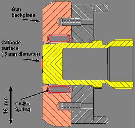
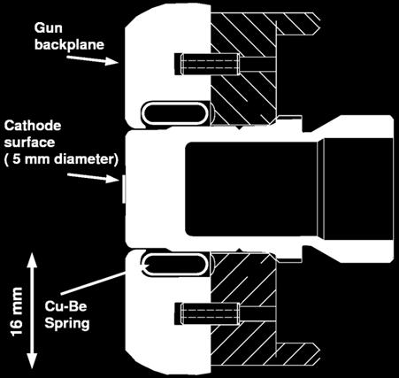
3 Cathode in the RF Gun Photocathode inserted into the gun backplane 3/8
4 Quantum Efficiency QE(%).5*Q(nC)/E(µJ) The design asks for 7 nc/sec QE required for FLASH: >.5 % to keep the laser in a reasonable limit: within an average power of ~W Design of present laser accounts for QE=.5% with an overhead of a factor of 4 and has an average power of W (IR) Cs Te cathodes found to be the best choice 4/8


5 Photocathode Production: Preparation Chamber Photocathodes are LASA on Mo plugs under UHV condition. Transport Box Source holder Preparation LASA UHV Vacuum System - base pressure - mbar 6 sources slot available Te sources out of % pure element Cs sources from SAES High pressure Hg lamp and interference filter for online monitoring of QE during production Masking system 5 x UHV transport box Mo Plug Masking Masking 5/8
 4. Reflectivity measurement to check optical polishing Rough Surface 8 6 ArcCast R = 56.5 +.")
6 Production: from Mo plugs... Polishing procedure before after. Milling and/or lathing of the plug from the rod (arc cast / sintered). Buffer Chemical Polishing (BCP) 3. Polished to optical finishing (roughness about nm) 4. Reflectivity measurement to check optical polishing Rough Surface 8 6 ArcCast R = % reduced dark current by an one order of magnitude Optical Finished Sintered R = % 4 6/ Reflectivity [%]
 first, a thin layer of nm of Te is produced then Cs is evaporated at a rate of nm/min during the")
7 Production:...to photocathodes growth Cs Te photocathode receipe: during the evaporation, the plug is heated to C. The dimension of the film is determined by a circular masking (the actual one is 5mm diameter) first, a thin layer of nm of Te is produced then Cs is evaporated at a rate of nm/min during the deposition, the film is illuminated with UV (λ=54 nm) of a Hg-lamp to monitor the quantum efficiency. the evaporation is stopped, when the QE is at maximum. Active Area 5 mm Different stoichiometric compounds form during Cs deposition till the correct Cs/Te ratio is reached corresponding to the QE maximum After min of Te deposition After 45 min of Cs deposition 7/8
8 Production: diagnostic on photocathodes The photoemissive properties of produced cathodes are checked performing spectral response measurements and QE maps (also at different wavelengths). QE 54nm (Hg lamp, interferential filter, mm spot diameter) QE map:73-i(54nm) of cathode #73. (3-3-4), +/-4mm, step.5mm Spectral response (Hg lamp, interferential filters, 3mm spot diameter) QE (%).E+.E+.E+.E-.E-.E-3.E-4 Just after the deposition Photon Energy (ev) d=5mm QE map:73-i(54nm) of cathode #73. (3-3-4), +/-4mm, step.5mm /8


9 Production: from LASA to FLASH and PITZ Transport box Produced cathodes, are loaded in the transport box and shipped to FLASH or PITZ keeping the UHV condition. The box is then connected to the RF gun. Since 998, we have shipped to TTF phase I, FLASH and PITZ: 49 x Cs Te x KCsTe 5 x Mo Total transfers from LASA: 5 RF gun and FLASH linac 9/8


10 Production:The Photocathode Database Many of the data relative to photocathodes (production, operation, lifetimes) and transport box are stored in the photocathode database whose WEB-interface is available at: The database keeps track of the photocathodes in the different transport boxes and in the different labs (TTF, PITZ and LASA). /8
 Pico-Amperemeter cathodes cathode carrier.")
11 CW QE measurements: Experimental set-up The experimental set-up for the CW QE measurements is mainly composed by: towards the RF gun a high pressure Hg lamp towards the exchange chamber Interferential filters (39nm, 54nm, 97nm, 334nm) Pico-Amperemeter cathodes cathode carrier. na 3 V picoammeter neutral density filters lens interferential filter Hg lamp Power energy meter Neutral density filters Optical components ( lens, mirror, pin-holes) transport box anode viewport pin-hole power head n W power meter condenser pin-hole /8
12 CW QE measurements: Results DESY on March 3 6 Data have been fitted to evaluate: the 6nm and Eg+Ea Cathode Dep. data QE@54nm (LASA) Operation lifetimes QE@54nm (DESY) QE@6nm (DESY) Eg+Ea (ev) Mar-5 7.9% 86.64%.79% Mar-5 9.% 66.44%.33% Sep-4 7.% 6.%.5% 4.57 Cathode 73. Cathode 7. Cathode 3. Cathode Eg+Ea =4.654eV - QE (@6 nm) =.7873% - Slope =.47 Experimental Fit QE (@6 nm) =.79% Cathode 7. - Eg+Ea =4.68eV - QE (@6 nm) =.3676% - Slope =.4 - QE (@6 nm) =.33% Cathode 3. - Eg+Ea =4.57eV - QE (@6 nm) =.5369% - Slope =.6575 Experimental Fit - QE (@6 nm) =.5% QE [%] - QE [%] QE [%] Experimental Fit photon energy [ev] photon energy [ev] / photon energy [ev]
13 CW QE measurements: Data Analysis CW data analysis Fitting of the spectral response [ h ( )] m QE = A ν E G + E A where A is a constant, E G and E A are energy gap and electron affinity. Cathode Eg+Ea =4.654eV - QE (@6 nm) =.7873% - Slope =.47 Experimental Fit QE (@6 nm) =.79% An example is given for the analysis of the CW QE data for cathode 73.. In this case: QE [%] - - Eg+Ea = 4.65 ev m =.4-3 Cathode # photon energy [ev] 3/8 (for a fresh Cs Te cathode we tipically have Eg+Ea = 3.5eV)
 and different energies. The laser energy has been measured using a Pyroelectric gauge (Joulemeter), varying the laser energy using the variable attenuator (λ/ wave plate + polarizer).")
14 Pulsed QE measurements: laser energy calibration experimental set-up The laser energy transmission (from the laser hut to the tunnel) has been evaluated for different iris diameters (3.5mm,.mm and.6mm) and different energies. The laser energy has been measured using a Pyroelectric gauge (Joulemeter), varying the laser energy using the variable attenuator (λ/ wave plate + polarizer). λ/ plate Joulemeter polarizer movable mirror mirror 4/8
 and reflectivity of the vacuum laser mirror (9 %) are accounted for")
![Energy [μj] O:\TESLA\TTF\QE\3-3-6\6-3-3T493-QE.dat.5 Laser Room.5.5 4 6 8 Attenuator Step O:\TESLA\TTF\QE\energy calibration\cal-pyro-336_65iris.](/docs-images/72/67625826/images/15-1.jpg "txt Mean trasnmission:7.78 [%]above4steps.5.8 Tunnel Energy [μj].4.3.. iris = 3.")
![5 mm as an example: sin fit sin fit 4 6 8 Attenuator Step Laser room / tunnel sin (Laser room) / sin (tunnel) Mean trasnmission:4.868 [%]above4steps.5.45.](/docs-images/72/67625826/images/15-2.jpg "4.35.3 4 6 8 Attenuator Step.75.7.65.6 iris =65.")
15 Pulsed QE measurements: laser beamline transmission analysis The QE measurement procedure uses the laser energy measured on the laser table Transmission to the vacuum window is regularly measured Transmission of the vacuum window (9 %) and reflectivity of the vacuum laser mirror (9 %) are accounted for Energy [μj] O:\TESLA\TTF\QE\3-3-6\6-3-3T493-QE.dat.5 Laser Room Attenuator Step O:\TESLA\TTF\QE\energy calibration\cal-pyro-336_65iris.txt Mean trasnmission:7.78 [%]above4steps.5.8 Tunnel Energy [μj] iris = 3.5 mm as an example: sin fit sin fit Attenuator Step Laser room / tunnel sin (Laser room) / sin (tunnel) Mean trasnmission:4.868 [%]above4steps Attenuator Step iris = Attenuator Step 5/8 Laser energy is measured as a function of the variable attenuator setting fitted by sin to evaluate the transmission Iris = 3.5 mm Iris =. mm Iris =.6 mm (σ)
16 Pulsed QE measurements: laser beam line transmission measurements The laser beamline transmission has been evaluated four times (from March to August 6) to take care of changes in the optical transmission path. Iris Φ (mm) Iris (step) Date (tunnel file) Date (laser room file) Transmission Used Mar-6 -Mar-6 3. % -Mar-6 -Mar not done not done % Mar-6 3-Mar-6 7. % Mar-6 3-Mar % Mar-6 3-Mar-6.85% not done not done June-6 6-June %.6 88 not done not done - From March to 3 March From 3 March to 6 June From 6 June to 7 Aug not done not done - From Aug-6 7-Aug % August till now.6 88 not done not done - 6/8
17 Pulsed QE measurements: measurement analysis The QE measurement is done following this procedure:. Measurement of the charge (toroid T, Q[C]).Measurement of the laser energy (laser hut) E 3.Calculation of the energy on the cathode E cath [J] using transmission (considering the losses due to the vacuum window and mirror) 3 [ ] QE % = nel nph = [ ] Eph[ ev] E [ J] Q C cath 6 nm: QE(%).5*Q(nC)/E(µJ) QE =3.% O:\TESLA\TTF\QE\4-3-6\6-3-4T88-QE.dat.5 The QE value is then obtained fitting the charge low charge to be sure not to be affected by the space charge Charge (nc).5 space charge effect.5 The relative and systematic error are in the order of %. 7/ Laser Energy (uj) The systematic error is mainly due to the uncertainty of identifying the linear part for the fit and due to the transmission measurement uncertainty
18 Pulsed QE measurements: cathode lifetime QE of cathodes are measured frequently within months. Example: cathode 7. and 73.. We define the end of lifetime when the QE reaches.5 % The CW QE of cathode 73. is compared with the pulsed QE measured the same day. The difference may be explained considering the increase of the charge due to the field enhancement. All cathodes show a drop of the QE over time, with different characteristics. QE (%) QE (%) Nov-5 4-Dec-5 3-Jan End of lifetime QE <.5% date End of lifetime QE <.5% 3-Mar-6 9-Mar-6 5-Mar-6 3-Mar-6 6-Apr-6 8/8 date 7. mean 7. CW_7. -Feb-6 4-Mar-6 3-Apr mean 73. CW_73.
19 Pulsed QE measurements: drop of QE with time We can relate the drop of QE with the vacuum condition in the RF gun. As an example, early 6, the RF gun has been operated with 3 μs long RF pulses. Up to this, the pulse length was restricted to 7 μs. During the long pulse operation period, the pressure increased from 5 7 mbar to mbar. This coincides with the drop of QE of cathode 73.. QE (%) Mar-6 9-Mar-6 5-Mar-6 3-Mar-6 6-Apr-6 date 9/8 End of lifetime QE <.5% 73. mean 73. CW_73.
.")
 different growth of the cathode during deposition damaging due to dark")
20 Pulsed QE measurements: cathode 78. Referring to cathode 78., several measurements have been done during about 3 months (period: April, 9 to July, ). Also this cathode shows a drop of the QE vs. time. 35 long pulse operation (increase of vacuum) different growth of the cathode during deposition damaging due to dark current coming from ACC CW_78. mean just after the deposition QE (%) during operation 3-Apr-6 3-Apr-6 3-May-6 -Jun-6 -Jun-6 -Jul-6 date /8
21 QE (%) Comparison between: Pulsed QE and CW QE measurements 7. mean 7. CW_7. The pulsed QE measurements of cathode 7. and 73. have been compared with the CW QE λ = 6nm, evaluated from the spectral response mean 73. CW_73. 4-Nov-5 4-Dec-5 3-Jan-6 -Feb-6 4-Mar-6 3-Apr-6 date CW 6nm The CW QE respect to the pulsed QE value is lower: QE (%) Mar-6 9-Mar-6 5-Mar-6 3-Mar-6 6-Apr-6 date this can be due to the high accelerating field on the cathode in pulsed QE measurements. /8
22 Pulsed QE measurements: QE vs. phase laser/rf gun Measurements have been performed on two cathodes varying the laser/rf gun phase. For cathodes 7. and 78., the measured 7 deg is higher respect to the one 38 deg cathode #7. cathode # QE (%) iris = 3.5mm iris = mm mean QE (a.u.) RF phase 9 iris = 3.5mm iris = mm mean RF phase /8
23 Pulsed QE measurements: analysis () RF data analysis QE enhancement given acc. gradient E acc and phase φ with a given laser energy without space charge QE = A hν ( E + E ) G A + q e q e β Eacc sin 4 π ε ( φ) m where E acc is the accelerating field, φ is the phase RF/laser, β is geometric enhancing factor Using the values calculated before for A, E G +E A and m, the geometric enhancing factor results: β= QE [%].6.4. with E acc = 4.9 MV/m and the phase φ = 38 from the experimental measurement..8 3/8 cathode Eacc [MV/m]
24 RF data analysis Laser spot profile influence.5 Pulsed QE measurements: analysis () given E acc and φ, at different laser energies Space charge forces have to be taken into account and depends on the laser transverse profile. Square profile Gaussian profile.5.5 Laser Beam Transverse Profile Laser spot radius Laser spot radius Charge.5 q c E acc_gun φ π, π r 8 beam nc Extracted Charge vs. Laser Energy Charge.5 q c E acc_gun φ π, π r 8 beam nc Laser Energy Laser Energy 4/8
25 Pulsed QE measurements: Comments to the analysis The influence of the laser spot profile mainly affects the shape of the charge vs. laser energy curves. With this simple model, we can explain the shape of the curve and some of the asymptotic values. It would be very helpful to have CW QE and pulsed QE measurements in the same day (QE constant) to further study the model. 3 QE :3.3[%]; spot diameter:3.8586[mm]; laser sigma:.99[mm] Example for cathode Laser spot/iris diameter = 3.5mm. Extrapolated spot size = 3.8mm. QE from the linear fit = 3.% QE from this analysis = 3.3% Charge [nc].5 Experimental Fit Laser energy [μj] 5/8


26 Pulsed QE measurements: QE map () QE maps by scanning a small laser spot over the cathode tiny iris =.6mm (σ), step size.3 mm. Map of the charge emitted from the cathode moving the iris only. cathode 73. Map of charge emitted from the cathode moving iris and mirror together. The photoemissive layer is 5 mm in diameter. Well reproduced, center position: (-.,-.) mm. 5mm diameter of the photoemissive layer 6/8
27 Pulsed QE measurements: QE map () QE maps cathode 77., used to center the laser beam on the cathode. QE maps before alignment QE map of cathode 77. after centering of the laser beam 7/8
28 Conclusion CW QE measurements: Experimental set-up in the tunnel The CW QE of 3 cathodes has been FLASH Pulsed QE measurements: Laser beamline transmission calibration QE vs. time and vs. RF phases Analysis of the pulsed QE measurements: QE maps E acc, RF phase, etc. Tool to check the centering between the laser spot and the photoemissive film For the future On-line measurements of the laser beamline transmission 8/8
Cathode Studies at FLASH: CW and Pulsed QE measurements
 Cathode Studies at FLASH: CW and Pulsed QE measurements L. Monaco, D. Sertore, P. Michelato S. Lederer, S. Schreiber Work supported by the European Community (contract number RII3-CT-2004-506008) 1/27
Photocathode activity for. P. Michelato
 Photocathode activity for FLASH and PITZ P. Michelato INFN Milano LASA Our Production at glance 5 Oct 6 49 Cs Te (37+1) KCsTe ( + ) 5 Mo (11+14) http://wwwlasa.mi.infn.it/ttfcathodes Main Topics Preparation
Results of recent photocathode studies at FLASH. S. Lederer, S. Schreiber DESY. L. Monaco, D. Sertore, P. Michelato INFN Milano LASA
 Results of recent photocathode studies at FLASH S. Lederer, S. Schreiber DESY L. Monaco, D. Sertore, P. Michelato INFN Milano LASA FLASH seminar October 21 st, 2008 Outlook Cs 2 Te photocathodes cw QE
Summary of recent photocathode studies
 Summary of recent photocathode studies S. Lederer, S. Schreiber DESY L. Monaco, D. Sertore INFN Milano LASA FLASH seminar November 17 th, 2009 Outlook Cs 2 Te photocathodes Pulsed QE measurements laser
High QE Photocathodes lifetime and dark current investigation
 High QE Photocathodes lifetime and dark current investigation Paolo Michelato INFN Milano - LASA Main Topics High QE photocathode lifetime QE vs. time (measurements on several cathodes, FLASH data) QE
Photoinjector Laser Operation and Cathode Performance
 Photoinjector Laser Operation and Cathode Performance Daniele Sertore, INFN Milano LASA Siegfried Schreiber, DESY Laser operational experience Laser beam properties Cathode performances Outlook TTF and
INFN Milano LASA News on Cathode Development
 INFN Milano LASA News on Cathode Development PITZ Collaboration Meeting December 7 8, 2010 L. Monaco and D. Sertore, INFN Milano LASA Presented dby D. Sertore 1 Outline LASA preparation system status t
First operation of cesium telluride photocathodes in the TTF injector RF gun
 Nuclear Instruments and Methods in Physics Research A 445 (2000) 422}426 First operation of cesium telluride photocathodes in the TTF injector RF gun D. Sertore *, S. Schreiber, K. Floettmann, F. Stephan,
RUNNING EXPERIENCE OF FZD SRF PHOTOINJECTOR
 RUNNING EXPERIENCE OF FZD SRF PHOTOINJECTOR Rong Xiang On behalf of the BESSY-DESY-FZD-MBI collaboration and the ELBE team FEL 2009, Liverpool, United Kingdom, August 23 ~ 28, 2009 Outline Introduction
Design Studies For The LCLS 120 Hz RF Gun Injector
 BNL-67922 Informal Report LCLS-TN-01-3 Design Studies For The LCLS 120 Hz RF Gun Injector X.J. Wang, M. Babzien, I. Ben-Zvi, X.Y. Chang, S. Pjerov, and M. Woodle National Synchrotron Light Source Brookhaven
Non-Invasive Energy Spread Monitoring for the JLAB Experimental Program via Synchrotron Light Interferometers
 Non-Invasive for the JLAB Experimental Program via Synchrotron Light Interferometers P. Chevtsov, T. Day, A.P. Freyberger, R. Hicks Jefferson Lab J.-C. Denard Synchrotron SOLEIL 20th March 2005 1. Energy
Operation of CEBAF photoguns at average beam current > 1 ma
 Operation of CEBAF photoguns at average beam current > 1 ma M. Poelker, J. Grames, P. Adderley, J. Brittian, J. Clark, J. Hansknecht, M. Stutzman Can we improve charge lifetime by merely increasing the
Performance of a DC GaAs photocathode gun for the Jefferson lab FEL
 Nuclear Instruments and Methods in Physics Research A 475 (2001) 549 553 Performance of a DC GaAs photocathode gun for the Jefferson lab FEL T. Siggins a, *, C. Sinclair a, C. Bohn b, D. Bullard a, D.
P. Emma, et al. LCLS Operations Lectures
 P. Emma, et al. LCLS Operations Lectures LCLS 1 LCLS Accelerator Schematic 6 MeV 135 MeV 250 MeV σ z 0.83 mm σ z 0.83 mm σ z 0.19 mm σ δ 0.05 % σ δ 0.10 % σ δ 1.6 % Linac-0 L =6 m rf gun L0-a,b Linac-1
Summary of the 1 st Beam Line Review Meeting Injector ( )
") Summary of the 1 st Beam Line Review Meeting Injector (23.10.2006) 15.11.2006 Review the status of: beam dynamics understanding and simulations completeness of beam line description conceptual design of
Summary of the 1 st Beam Line Review Meeting Injector (23.10.2006) 15.11.2006 Review the status of: beam dynamics understanding and simulations completeness of beam line description conceptual design of
Tutorial: Trak design of an electron injector for a coupled-cavity linear accelerator
 Tutorial: Trak design of an electron injector for a coupled-cavity linear accelerator Stanley Humphries, Copyright 2012 Field Precision PO Box 13595, Albuquerque, NM 87192 U.S.A. Telephone: +1-505-220-3975
TESLA FEL-Report
 Determination of the Longitudinal Phase Space Distribution produced with the TTF Photo Injector M. Geitz a,s.schreiber a,g.von Walter b, D. Sertore a;1, M. Bernard c, B. Leblond c a Deutsches Elektronen-Synchrotron,
Screen investigations for low energetic electron beams at PITZ
 1 Screen investigations for low energetic electron beams at PITZ S. Rimjaem, J. Bähr, H.J. Grabosch, M. Groß Contents Review of PITZ setup Screens and beam profile monitors at PITZ Test results Summary
Performance of the MCP-PMT for the Belle II TOP counter
 Performance of the MCP-PMT for the Belle II TOP counter Kodai Matsuoka (KMI, Nagoya Univ.) S. Hirose, T. Iijima, K. Inami, Y. Kato, Y. Maeda, R. Mizuno, Y. Sato, K. Suzuki (Nagoya Univ.) TOP (Time Of Propagation)
Dark current and multipacting trajectories simulations for the RF Photo Gun at PITZ
 Dark current and multipacting trajectories simulations for the RF Photo Gun at PITZ Introduction The PITZ RF Photo Gun Field simulations Dark current simulations Multipacting simulations Summary Igor Isaev
Activities on FEL Development and Application at Kyoto University
 Activities on FEL Development and Application at Kyoto University China-Korea-Japan Joint Workshop on Electron / Photon Sources and Applications Dec. 2-3, 2010 @ SINAP, Shanghai Kai Masuda Inst. Advanced
Detailed Design Report
 Detailed Design Report Chapter 4 MAX IV Injector 4.6. Acceleration MAX IV Facility CHAPTER 4.6. ACCELERATION 1(10) 4.6. Acceleration 4.6. Acceleration...2 4.6.1. RF Units... 2 4.6.2. Accelerator Units...
High Rep Rate Guns: FZD Superconducting RF Photogun
 High Rep Rate Guns: FZD Superconducting RF Photogun J. Teichert, A. Arnold, H. Büttig, D. Janssen, M. Justus, U. Lehnert, P. Michel, K. Moeller, P. Murcek, Ch. Schneider, R. Schurig, G. Staats, F. Staufenbiel,
SIMULTANEOUS OPERATION OF THREE LASER SYSTEMS AT THE FLASH PHOTOINJECTOR
 SIMULTANEOUS OPERATION OF THREE LASER SYSTEMS AT THE FLASH PHOTOINJECTOR S. Schreiber, J. Roensch-Schulenburg, B. Steffen, C. Gruen, K. Klose, DESY, Hamburg, Germany Abstract The free-electron laser facility
SRF-gun Development Overview. J. Sekutowicz 17 th September, 2015 SRF15, Whistler, Canada
 SRF-gun Development Overview J. Sekutowicz 17 th September, 2015 SRF15, Whistler, Canada Acknowledgment Many thanks to: A. Arnold, J. Hao, E. Kako, T. Konomi, D. Kostin, J. Lorkiewicz, A. Neumann, J. Teichert
Study of Timing and Efficiency Properties of Multi-Anode Photomultipliers
 Study of Timing and Efficiency Properties of Multi-Anode Photomultipliers T. Hadig, C.R. Field, D.W.G.S. Leith, G. Mazaheri, B.N. Ratcliff, J. Schwiening, J. Uher, J. Va vra Stanford Linear Accelerator
Photo cathode RF gun -
 Photo cathode RF gun - *),,, ( 05 Nov. 2004 Spring8 UTNL Linac & Mg Photocathode RF Gun Mg photocathode NERL, 18 MeV Linac and the RF gun Electron Beam Mg photocathode Mg photocathode RF gun of SPring8
Status of the Jefferson Lab Polarized Beam Physics Program and Preparations for Upcoming Parity Experiments
 Status of the Jefferson Lab Polarized Beam Physics Program and Preparations for Upcoming Parity Experiments P. Adderley, M. Baylac, J. Clark, A. Day, J. Grames, J. Hansknecht, M. Poelker, M. Stutzman PESP
Commissioning the TAMUTRAP RFQ cooler/buncher. E. Bennett, R. Burch, B. Fenker, M. Mehlman, D. Melconian, and P.D. Shidling
 Commissioning the TAMUTRAP RFQ cooler/buncher E. Bennett, R. Burch, B. Fenker, M. Mehlman, D. Melconian, and P.D. Shidling In order to efficiently load ions into a Penning trap, the ion beam should be
Diamond RF Status (RF Activities at Daresbury) Mike Dykes
 Mike Dykes") Diamond RF Status (RF Activities at Daresbury) Mike Dykes ASTeC What is it? What does it do? Diamond Status Linac Booster RF Storage Ring RF Summary Content ASTeC ASTeC was formed in 2001 as a centre of
Diamond RF Status (RF Activities at Daresbury) Mike Dykes ASTeC What is it? What does it do? Diamond Status Linac Booster RF Storage Ring RF Summary Content ASTeC ASTeC was formed in 2001 as a centre of
DARK CURRENT IN SUPERCONDUCTING RF PHOTOINJECTORS MEASUREMENTS AND MITIGATION
 DARK CURRENT IN SUPERCONDUCTING RF PHOTOINJECTORS MEASUREMENTS AND MITIGATION J. Teichert #, A. Arnold, P. Murcek, G. Staats, R. Xiang, HZDR, Dresden, Germany P. Lu, H. Vennekate, HZDR & Technische Universität,
30 GHz Power Production / Beam Line
 30 GHz Power Production / Beam Line Motivation & Requirements Layout Power mode operation vs. nominal parameters Beam optics Achieved performance Problems Beam phase switch for 30 GHz pulse compression
SLAC R&D Program for a Polarized RF Gun
 ILC @ SLAC R&D Program for a Polarized RF Gun SLAC-PUB-11657 January 2006 (A) J. E. CLENDENIN, A. BRACHMANN, D. H. DOWELL, E. L. GARWIN, K. IOAKEIMIDI, R. E. KIRBY, T. MARUYAMA, R. A. MILLER, C. Y. PRESCOTT,
PHGN 480 Laser Physics Lab 4: HeNe resonator mode properties 1. Observation of higher-order modes:
 PHGN 480 Laser Physics Lab 4: HeNe resonator mode properties Due Thursday, 2 Nov 2017 For this lab, you will explore the properties of the working HeNe laser. 1. Observation of higher-order modes: Realign
The FLASH objective: SASE between 60 and 13 nm
 Injector beam control studies winter 2006/07 talk from E. Vogel on work performed by W. Cichalewski, C. Gerth, W. Jalmuzna,W. Koprek, F. Löhl, D. Noelle, P. Pucyk, H. Schlarb, T. Traber, E. Vogel, FLASH
VERY HIGH VOLTAGE PHOTOEMISSION ELECTRON GUNS*
 VERY HIGH VOLTAGE PHOTOEMISSION ELECTRON GUNS* Charles K. Sinclair #, Cornell University, Ithaca, NY 14853, USA Abstract There are a growing number of applications for CW electron accelerators, many requiring
Digital BPMs and Orbit Feedback Systems
 Digital BPMs and Orbit Feedback Systems, M. Böge, M. Dehler, B. Keil, P. Pollet, V. Schlott Outline stability requirements at SLS storage ring digital beam position monitors (DBPM) SLS global fast orbit
The SLAC Polarized Electron Source *
 SLAC-PUB-9509 October 2002 The SLAC Polarized Electron Source * J. E. Clendenin, A. Brachmann, T. Galetto, D.-A. Luh, T. Maruyama, J. Sodja, and J. L. Turner Stanford Linear Accelerator Center, 2575 Sand
Technology Challenges for SRF Guns as ERL Sources in View of Rossendorf work
 Technology Challenges for SRF Guns as ERL Sources in View of Rossendorf work, Hartmut Buettig, Pavel Evtushenko, Ulf Lehnert, Peter Michel, Karsten Moeller, Petr Murcek, Christof Schneider, Rico Schurig,
POLARIZED LIGHT SOURCES FOR PHOTOCATHODE ELECTRON GUNS AT SLAC?
 SLAC-PUB-5965 December 1992 (4 POLARIZED LIGHT SOURCES FOR PHOTOCATHODE ELECTRON GUNS AT SLAC? M. Woods,O J. Frisch, K. Witte, M. Zolotorev Stanford Linear Accelerator Center Stanford University, Stanford,
4.4 Injector Linear Accelerator
 4.4 Injector Linear Accelerator 100 MeV S-band linear accelerator based on the components already built for the S-Band Linear Collider Test Facility at DESY [1, 2] will be used as an injector for the CANDLE
Experience with the Cornell ERL Injector SRF Cryomodule during High Beam Current Operation
 Experience with the Cornell ERL Injector SRF Cryomodule during High Beam Current Operation Matthias Liepe Assistant Professor of Physics Cornell University Experience with the Cornell ERL Injector SRF
Current status of XFEL/SPring-8 project and SCSS test accelerator
 Current status of XFEL/SPring-8 project and SCSS test accelerator Takahiro Inagaki for XFEL project in SPring-8 inagaki@spring8.or.jp Outline (1) Introduction (2) Key technology for compactness (3) Key
PHIN. Report on the Development of a Radio-Frequency Photo Electron Source with Superconducting Niobium Cavity (SRF Gun Realization)
") PHIN Report on the Development of a Radio-Frequency Photo Electron Source with Superconducting Niobium Cavity (SRF Gun Realization) J. Teichert, A. Arnold, H. Buettig, R. Hempel, D. Janssen, U. Lehnert,
PHIN Report on the Development of a Radio-Frequency Photo Electron Source with Superconducting Niobium Cavity (SRF Gun Realization) J. Teichert, A. Arnold, H. Buettig, R. Hempel, D. Janssen, U. Lehnert,
Development of OLED Lighting Applications Using Phosphorescent Emission System
 Development of OLED Lighting Applications Using Phosphorescent Emission System Kazuhiro Oikawa R&D Department OLED Lighting Business Center KONICA MINOLTA ADVANCED LAYERS, INC. October 10, 2012 Outline
Jefferson Lab Experience with Beam Halo, Beam Loss, etc.
 Jefferson Lab Experience with Beam Halo, Beam Loss, etc. Pavel Evtushenko with a lot of input from many experienced colleagues Steve Benson, Dave Douglas, Kevin Jordan, Carlos Hernandez-Garcia, Dan Sexton,
Design and Simulation of High Power RF Modulated Triode Electron Gun. A. Poursaleh
 Design and Simulation of High Power RF Modulated Triode Electron Gun A. Poursaleh National Academy of Sciences of Armenia, Institute of Radio Physics & Electronics, Yerevan, Armenia poursaleh83@yahoo.com
TWO BUNCHES WITH NS-SEPARATION WITH LCLS*
 TWO BUNCHES WITH NS-SEPARATION WITH LCLS* F.-J. Decker, S. Gilevich, Z. Huang, H. Loos, A. Marinelli, C.A. Stan, J.L. Turner, Z. van Hoover, S. Vetter, SLAC, Menlo Park, CA 94025, USA Abstract The Linac
RF considerations for SwissFEL
 RF considerations for H. Fitze in behalf of the PSI RF group Workshop on Compact X-Ray Free Electron Lasers 19.-21. July 2010, Shanghai Agenda Introduction RF-Gun Development C-band development Summary
The basic parameters of the pre-injector are listed in the Table below. 100 MeV
 3.3 The Pre-injector The high design brightness of the SLS requires very high phase space density of the stored electrons, leading to a comparatively short lifetime of the beam in the storage ring. This,
FEL Gun Test Stand (GTS) from construction to beam operations
 from construction to beam operations") FEL Gun Test Stand (GTS) from construction to beam operations Carlos Hernandez-Garcia for the FEL team CASA Beam Physics Seminar June 19 2008 The DC photocathode gun Outline The enclosure and all other
FEL Gun Test Stand (GTS) from construction to beam operations Carlos Hernandez-Garcia for the FEL team CASA Beam Physics Seminar June 19 2008 The DC photocathode gun Outline The enclosure and all other
Present Status and Future Upgrade of KEKB Injector Linac
 Present Status and Future Upgrade of KEKB Injector Linac Kazuro Furukawa, for e /e + Linac Group Present Status Upgrade in the Near Future R&D towards SuperKEKB 1 Machine Features Present Status and Future
AREAL- Phase 1. B. Grigoryan on behalf of AREAL team
 AREAL- Phase 1 Progress & Status B. Grigoryan on behalf of AREAL team Contents Machine Layout Building & Infrastructure Laser System RF System Vacuum System Cooling System Control System Beam Diagnostics
TTF / VUV-FEL. Schedule 2005 and Project Management Issues. Schedule 2005 Project Organisation Budget & Controlling
 TTF / VUV-FEL Schedule 200 and Project Management Issues Schedule 200 Project Organisation Budget & Controlling Hans Weise / DESY DESY MAC Meeting November 9th, 2004 TTF Linac Start-up After Final Installation
Beam Losses During LCLS Injector Phase-1 1 Operation
 Beam Losses During LCLS Injector Phase-1 1 Operation & Paul Emma September 28, 2006 Radiation Safety Committee Review Scope of Phase 1 Operation Request for Three Operating Modes Operating Plan for Phase
Display Systems. Viewing Images Rochester Institute of Technology
 Display Systems Viewing Images 1999 Rochester Institute of Technology In This Section... We will explore how display systems work. Cathode Ray Tube Television Computer Monitor Flat Panel Display Liquid
Beam test of the QMB6 calibration board and HBU0 prototype
 Beam test of the QMB6 calibration board and HBU0 prototype J. Cvach 1, J. Kvasnička 1,2, I. Polák 1, J. Zálešák 1 May 23, 2011 Abstract We report about the performance of the HBU0 board and the optical
Technology Challenges for SRF Guns as ERL Source in View of BNL Work
 Technology Challenges for SRF Guns as ERL Source in View of BNL Work Work being performed and supported by the Collider Accelerator Division of Brookhaven National Labs as well as the Office of Naval Research
EUROFEL-Report-2007-DS EUROPEAN FEL Design Study
 EUROFEL-Report-2007-DS4-095 EUROPEAN FEL Design Study Deliverable N : D 4.3 Deliverable Title: Task: Authors: Generation of 3rd harmonic photons at 90 nm DS-4 see next page Contract N : 011935 Project
First Results and Future of the Photo Injector Test Facility at DESY Zeuthen PITZ. introduction first measurements future schedule
 First Results and Future of the Photo Injector Test Facility at DESY Zeuthen PITZ introduction first measurements future schedule Frank Stephan for the PITZ Collaboration, TTF Meeting Saclay, April 3 rd
Simulations on Beam Monitor Systems for Longitudinal Feedback Schemes at FLASH.
 Simulations on Beam Monitor Systems for Longitudinal Feedback Schemes at FLASH. Christopher Behrens for the FLASH team Deutsches Elektronen-Synchrotron (DESY) FLS-2010 Workshop at SLAC, 4. March 2010 C.
BEAMAGE 3.0 KEY FEATURES BEAM DIAGNOSTICS PRELIMINARY AVAILABLE MODEL MAIN FUNCTIONS. CMOS Beam Profiling Camera
 PRELIMINARY POWER DETECTORS ENERGY DETECTORS MONITORS SPECIAL PRODUCTS OEM DETECTORS THZ DETECTORS PHOTO DETECTORS HIGH POWER DETECTORS CMOS Beam Profiling Camera AVAILABLE MODEL Beamage 3.0 (⅔ in CMOS
The temperature management of photo cathodes at MAMI and MESA
 The temperature management of photo cathodes at MAMI and MESA V. Tioukine, SFB-1044, PRISMA, KPH Uni Mainz 15th Sept, 2017, Contents MESA Photo cathodes Currently used Cooling of the cathodes Present,
Suppression of Timing drift between laser and electron beam driven photo-cathode RF gun
 Suppression of Timing drift between laser and electron beam driven photo-cathode RF gun A. Sakumi, M. Uesaka, Y. Muroya, T. Ueda Nuclear Professional School, University of Tokyo J. Urakawa, KEK, Japan
Recent APS Storage Ring Instrumentation Developments. Glenn Decker Advanced Photon Source Beam Diagnostics March 1, 2010
 Recent APS Storage Ring Instrumentation Developments Glenn Decker Advanced Photon Source Beam Diagnostics March 1, 2010 Ring Diagnostics Overview RF beam position monitor technology Photon beam position
-Sharp Telecentric backlight illuminator by EFFILUX
 -Sharp Telecentric backlight illuminator by EFFILUX EFFI-Telecentric is a telecentric backlight illuminator used to get rid of the undesired effects obtained with a diffuse backlighting system It is highly
High Brightness Injector Development and ERL Planning at Cornell. Charlie Sinclair Cornell University Laboratory for Elementary-Particle Physics
 High Brightness Injector Development and ERL Planning at Cornell Charlie Sinclair Cornell University Laboratory for Elementary-Particle Physics June 22, 2006 JLab CASA Seminar 2 Background During 2000-2001,
Development of a Compact Load Lock System and a New Tuning Structurer for a Cs2Te Cathode RF Gun. Yoshio Kamiya, Waseda Univ.
 Development of a Compact Load Lock System and a New Tuning Structurer for a Cs2Te Cathode RF Gun Yoshio Kamiya, Waseda Univ. Works done by Advanced Research Institute for Science and Engineering, Waseda
Beam Instrumentation for X-ray FELs
 Beam Instrumentation for X-ray FELs 05/16/2011 1 1 Outline X-ray FEL overview Diagnostics requirements for X-ray FELs Transverse Diagnostics Longitudinal Diagnostics Summary 2 2 X-ray FEL Overview 100
INFN School on Electron Accelerators. RF Power Sources and Distribution
 INFN School on Electron Accelerators 12-14 September 2007, INFN Sezione di Pisa Lecture 7b RF Power Sources and Distribution Carlo Pagani University of Milano INFN Milano-LASA & GDE The ILC Double Tunnel
Mahdad Manavi LOTS Technology, Inc.
 Presented by Mahdad Manavi LOTS Technology, Inc. 1 Authors: Mahdad Manavi, Aaron Wegner, Qi-Ze Shu, Yeou-Yen Cheng Special Thanks to: Dan Soo, William Oakley 2 25 MB/sec. user data transfer rate for both
LCOS-SLM (Liquid Crystal on Silicon - Spatial Light Modulator)
") POWER LCOS-SLM CONTROLLER RESET POWER OUTPUT ERROR LCOS-SLM (Liquid Crystal on Silicon - Spatial Light Modulator) Control your light! Shape your beam! Improve your image! The devices are a reflective type
POWER LCOS-SLM CONTROLLER RESET POWER OUTPUT ERROR LCOS-SLM (Liquid Crystal on Silicon - Spatial Light Modulator) Control your light! Shape your beam! Improve your image! The devices are a reflective type
Commissioning program of the 704 MHz SRF gun at BNL
 BROOKHAVEN SCIENCE ASSOCIATES Commissioning program of the 704 MHz SRF gun at BNL Brookhaven National Laboratory ERL workshop June 7-12 2015 1 Outline Brief Introduction of the BNL R&D ERL and SRF gun
New Filling Pattern for SLS-FEMTO
 SLS-TME-TA-2009-0317 July 14, 2009 New Filling Pattern for SLS-FEMTO Natalia Prado de Abreu, Paul Beaud, Gerhard Ingold and Andreas Streun Paul Scherrer Institut, CH-5232 Villigen PSI, Switzerland A new
NEW ELLIPSOIDAL LASER AT THE UPGRADED PITZ FACILITY
 Proceedings of FEL05, Daejeon, Korea NEW ELLIPSOIDAL LASER AT THE UPGRADED PITZ FACILITY J. Good #, G. Asova, M. Bakr, P. Boonpornprasert, M. Gross, C. Hernandez-Garcia, H. Huck, I. Isaev, D. Kalantaryan,
Implementation of the feed forward correction for the FLASH photo injector laser and future plans for a feedback system
 Implementation of the feed forward correction for the FLASH photo injector laser and future plans for a feedback system Sebastian Schulz 1,2, Vladimir Arsov 2, Patrick Gessler 2, Olaf Hensler 2, Karsten
Scalable self-aligned active matrix IGZO TFT backplane technology and its use in flexible semi-transparent image sensors. Albert van Breemen
 Scalable self-aligned active matrix IGZO TFT backplane technology and its use in flexible semi-transparent image sensors Albert van Breemen Image sensors today 1 Dominated by silicon based technology on
Drive Laser Operations
 Drive-Laser Operations Drive Laser Thales laser Transport system Recent Laser Milestones Safety Technical Where do we stand today? Laser Acceptance Status Laser Commissioning UV on cathode Injector Commissioning
Status of JRA-SRF in CARE
 Status of JRA-SRF in CARE Reminder JRA-SRF: Strategy, Partner, financial volume Where do we stand in JRA-SRF today Progress in work-packages, schedule Administrative & financial issues What is next First
Basic rules for the design of RF Controls in High Intensity Proton Linacs. Particularities of proton linacs wrt electron linacs
 Basic rules Basic rules for the design of RF Controls in High Intensity Proton Linacs Particularities of proton linacs wrt electron linacs Non-zero synchronous phase needs reactive beam-loading compensation
Light Emitting Diodes
 By Kenneth A. Kuhn Jan. 10, 2001, rev. Feb. 3, 2008 Introduction This brief introduction and discussion of light emitting diode characteristics is adapted from a variety of manufacturer data sheets and
SPEAR 3: Operations Update and Impact of Top-Off Injection
 SPEAR 3: Operations Update and Impact of Top-Off Injection R. Hettel for the SSRL ASD 2005 SSRL Users Meeting October 18, 2005 SPEAR 3 Operations Update and Development Plans Highlights of 2005 SPEAR 3
Soft x-ray optical diagnostics, concepts and issues for NGLS
 Soft x-ray optical diagnostics, concepts and issues for NGLS Tony Warwick (for the NGLS project team) EuroXFEL user meeting 2013 Satellite workshop on photon beam diagnostics 24 January 2013 NGLS approach
Next Linear Collider. The 8-Pack Project. 8-Pack Project. Four 50 MW XL4 X-band klystrons installed on the 8-Pack
 The Four 50 MW XL4 X-band klystrons installed on the 8-Pack The Demonstrate an NLC power source Two Phases: 8-Pack Phase-1 (current): Multi-moded SLED II power compression Produce NLC baseline power: 475
SPATIAL LIGHT MODULATORS
 SPATIAL LIGHT MODULATORS Reflective XY Series Phase and Amplitude 512x512 A spatial light modulator (SLM) is an electrically programmable device that modulates light according to a fixed spatial (pixel)
The Construction Status of CSNS Linac
 The Construction Status of CSNS Linac Sheng Wang Dongguan branch, Institute of High Energy Physics, CAS Sep.2, 2014, Geneva Outline The introduction to CSNS accelerators The commissoning of ion source
Industrial Diode Laser (IDL) System IDL Series
 System IDL Series") COMMERCIAL LASERS Industrial Diode Laser (IDL) System IDL Series Key Features Round, top-hat beam profile for uniform power distribution Warranted for full rated power in either pulsed or continuous wave
COMMERCIAL LASERS Industrial Diode Laser (IDL) System IDL Series Key Features Round, top-hat beam profile for uniform power distribution Warranted for full rated power in either pulsed or continuous wave
Capability Improvements: Polarized Photoinjector*
 Capability Improvements: Polarized Photoinjector* Matt Poelker Operations Review Jefferson Lab January 22 25, 2002 * represents ~ half of total procurement budget for Capability Improvements. Other improvements
UniMCO 4.0: A Unique CAD Tool for LED, OLED, RCLED, VCSEL, & Optical Coatings
 UniMCO 4.0: A Unique CAD Tool for LED, OLED, RCLED, VCSEL, & Optical Coatings 1 Outline Physics of LED & OLED Microcavity LED (RCLED) and OLED (MCOLED) UniMCO 4.0: Unique CAD tool for LED-Based Devices
LG Display OLED Light. 1. Corporate Overview 2. Market Trend 3. New Product 4. Advantages of OLED light 5. Applicable Areas 6.
 OLED Light 1 LG Display OLED Light 1. Corporate Overview 2. Market Trend 3. New Product 4. Advantages of OLED light 5. Applicable Areas 6. Price Indication 1. Corporate Overview LG Display offers a variety
Production of quasi-monochromatic MeV photon in a synchrotron radiation facility
 Production of quasi-monochromatic MeV photon in a synchrotron radiation facility Presentation at University of Saskatchewan April 22-23, 2010 Yoshitaka Kawashima Brookhaven National Laboratory NSLS-II,
LUT Luminescence scanners: Seeing what no-one else can
 LUT Luminescence scanners Luminescence scanners LUT Luminescence scanners: Seeing what no-one else can Special features: A semi-conductor light source is used in the LUT series no lamp change required.
12GeV CEBAF Commissioning
 12GeV CEBAF Commissioning Operations Dept. Accelerator Division JLAB Outline 1 Process Integrated Process Overview Accelerator Readiness Review Process Internal Reviews/Process Process Recap 2 Beam Commissioning
Applications Keypad Backlighting Symbol Backlighting Status Indication Front Panel Indicator
 Reverse Surface Mount Flip Chip LEDs Technical Data HSMS-H630/H730 HSMD-H630/H730 HSMY-H630/H730 HSMG-H630/H730 Features Reverse Mountable Surface Mount LED Breakthrough Reliability through Elimination
RF Design of the LCLS Gun C.Limborg, Z.Li, L.Xiao, J.F. Schmerge, D.Dowell, S.Gierman, E.Bong, S.Gilevich February 9, 2005
 RF Design of the LCLS Gun C.Limborg, Z.Li, L.Xiao, J.F. Schmerge, D.Dowell, S.Gierman, E.Bong, S.Gilevich February 9, 2005 Summary Final dimensions for the LCLS RF gun are described. This gun, referred
Compact, e-beam based mm-and THzwave light sources
 Compact, e-beam based mm-and THzwave light sources S.G. Biedron, S.V. Milton (CSU) and G.P. Gallerano (ENEA) Frontiers of THz Science Workshop Sept. 5-6, 2012 SLAC 1 Collaborators involved with the enclosed
25W 9xxnm Uncooled Multimode Laser Diode Module
 25W 9xxnm Uncooled Multimode Laser Diode Module BMU25-9xx-01/02-R Features: Single emitter based laser diode module High output power of 25W 0.15NA or 0.22NA 105μm core multimode optical fiber Hermetically
Low Frequency Gyrotrons for Fusion
 13th Joint Workshop on Electron Cyclotron Emission and Electron Cyclotron Resonance Heating Nizhny Novgorod, Russia May 17-20, 2004 РАН Low Frequency Gyrotrons for Fusion НПП ГИКОМ V.E. Zapevalov, Yu.K.
Product Description Sheet Loctite CL10 Quad LED Controller
 PRODUCT DESCRIPTION The is a UV-LED spot light source that emits UV light at 365 or 405 nm. The Quad Controller includes a footswitch and AC power cord. The required LED head is purchased separately and
G0 Laser Status Parity Controls Injector Diagnostics
 G0 Laser Status Parity Controls Injector Diagnostics G0 Collaboration Mtg Jefferson Lab August 16, 2002 G0 Collaboration Mtg (August 16, 2002), 1 Installed new AOM homebuilt laser G0 Collaboration Mtg