Nixie Clock Type SixNix
|
|
|
- Ross Richard
- 6 years ago
- Views:
Transcription

1 Assembly Instructions And User Guide Nixie Clock Type SixNix - 1 -
2 Issue Number Date REVISION HISTORY Reason for Issue 6 20 March 2014 Removed WWVB Support 5 14 July 2012 New Board Issue - 19 July Jan 2012 Added new fuse type 3 6 Sept 11 Added dimensioned drawing 2 5 Sept 11 Errors corrected 1 20 July 2011 New document - 2 -
3 1. INTRODUCTION 1.1 About the clock Nixie clock type SixNix is a compact design with all components and tubes mounted on a single PCB. The efficient use of board space is achieved by using a multiplex design to drive the display tubes. Only a single high-voltage binary-to-decimal decoder IC (74141) is required, and each tube is switched on in sequence very quickly to give the illusion that all the tubes are actually lit. The clock is designed for tube type IN Clock Features Nixie clock type SixNix' has the following features: - Hours, Minutes and Seconds display - 12 or 24 hour modes - Date display in either DD.MM.YY or MM.DD.YY format - Alarm, with programmable snooze period - Programmable date display each minute - Attractive LED tube lighting - Uses a Quartz Crystal Oscillator as the timebase - Optional DCF / MSF / GPS synchronisation with status indicator LED - Supercapacitor backup. Keeps time during short power outages - Simple time setting using two buttons - Programmable leading zero blanking - Five programmable neon colon settings (Flashing AM/PM indication, illuminated AM/PM indication, both flashing, both on, both off) - Maintains time during setup mode, eg. When changing between Standard Time and Daylight Savings Time - Seconds can be reset to zero to precisely the set time - Programmable night mode - blanked or dimmed display to save tubes or prevent sleep disturbance - Separate modes for colon neons during night mode - Standard or fading change of digits - Slot Machine Cathode poisoning prevention routine - All user preferences stored to non-volatile memory - 3 -
4 1.3 SAFETY DANGER: The clock pcb includes a switched-mode voltage booster circuit. This generates nominally 170 Volts DC, but is capable of generating up to 300 Volts before adjustment. Assembly may only be undertaken by individuals who are suitably qualified and experienced in electronics assembly, and are familiar with safe procedures for working with high voltages. If in doubt, refer to a suitably qualified engineer before proceeding. The voltages generated by this circuit can give a potentially LETHAL ELECTRIC SHOCK. DISCLAIMER: This product is supplied as a kit of parts, intended only for suitably qualified electronic engineers, who are suitably qualified and experienced in electronics assembly, and are familiar with safe procedures for working with high voltages. The supplier, his agents or associates accept no liability for any damage, injury or death arising from the use of this kit of parts. This is not a finished product, and the person assembling the kit is responsible for ensuring that the finished product complies with any applicable local regulations governing electrical equipment, eg. UL, CE, VDE
 - Wire cutters (TIP: A small pair of nail clippers works very well for this function) - Wire")
5 2. TOOLS AND EQUIPMENT REQUIRED 2.1 Tools required to assemble the PCB. The following tools will be required to assemble the PCB: - Soldering iron with a small tip (1-2 mm) - Wire cutters (TIP: A small pair of nail clippers works very well for this function) - Wire strippers (TIP: A small pair of scissors is quite suitable) - Multimeter for voltage tests and for identifying the resistors. - Small flat screwdriver for adjusting the high voltage supply 2.2 Materials you will need. Solder lead / tin solder is preferred. Lead free solder, as now required to be used in commercial products in Europe, has a much higher melting point and can be very hard to work with. Desoldering wick (braid) can be useful if you accidentally create solder bridges between adjacent solder joints. 2.3 Other items you will need The clock kit does not include a power adapter. This is because the kit is sold to many countries around the world, each with very different household mains outlet socket types. It is more efficient for the user to buy a suitable adapter locally. This saves shipping a heavy adapter with the kit, and also the extra costs of managing stocks of many varied power adapters. If you are using a DCF or MSF receiver avoid cheap Chinese switching power supplies, as they can cause interference problems: an adapter with an earth connection will be needed. The suitable type of power adapter can be obtained at very low cost. The following specification of adapter should be obtained and used with the kit: Output 12V DC regulated, minimum power output capability of 300 ma Output plug: 2.1mm pin, centre positive. A suitable adapter is shown below: - 5 -
6 3. LIST OF COMPONENTS 3.1 Table of components Circuit Designation Part Description Resistors R1, R2 4.7K, ¼ Watt R3 390K, ¼ Watt R4, R5 4.7K, ¼ Watt R6, R7 560R, ¼ Watt R8 4.7K, ¼ Watt R9, R10 560R, ¼ Watt R11 R24 4.7K, ¼ Watt R25 - R32 390K, ¼ Watt R33 R35 560R, ¼ Watt Capacitors C1 470uF 16-25V, Electrolytic C2 100nF Ceramic C3 1uF 250V Electrolytic C4 15pF Ceramic C5 33pF Ceramic C6 0.1F C7, C8 100nF Ceramic Transistors Q1 IRFD220 MOSFET Q2 Q10 MPSA42 NPN Q11 Q16 MPSA92 NPN Q17 MPSA42 NPN Diodes D1 D3 1N5819 D4 UF4004 D5 5mm Yellow LED D6 D8 1N4148 D9 D14 3mm Blue LED D15 5 mm Green LED Integrated Circuits IC V voltage regulator IC2 PIC16Fxxxx 8-bit microcontroller IC / K155ID1 Nixie driver Miscellaneous L1 100uH Radial Inductor AM, PM 4mm wire ended neon lamp SET, ADJ, ALARM Miniature push button IC Socket for IC2 28 Way IC socket for IC2 IC Socket for IC3 16 Way IC socket for IC32 J1 2.1mm PCB power socket LS1 Piezo sounder GPS/ RFT 3.5mm Jack socket FUSE 500mA fuse Insulation Clear insulation for neons X KHz watch crystal - 6 -
7 3.2 Parts list / Packing sheet Part Description Quantity Resistors 560R, ¼ Watt 7 4.7K, ¼ Watt K, ¼ Watt 9 Capacitors 470uF, 16-25V, Electrolytic 1 1uF 250V, Electrolytic 1 100nF Ceramic 3 15pF Ceramic 1 33pF Ceramic 1 0.1F 1 Transistors IRFD220 MOSFET 1 MPSA92 PNP 6 MPSA42 NPN 10 Diodes 1N UF4004 fast recovery diode 1 1N mm Yellow LED 1 5mm Green LED 1 3mm Blue LED 6 Integrated Circuits V voltage regulator 1 PIC16Fxxxx 8-bit microcontroller / K155ID1 Nixie driver 1 Miscellaneous 100uH Radial inductor 1 4mm wire ended neon lamp 2 Miniature push button 3 28 Way IC socket for IC Way IC socket for IC mm Jack socket 1 2.1mm PCB power socket 1 Piezo sounder 1 500mA fuse 1 6 cm clear insulation KHz watch crystal 1 It is recommended that the kit is checked against the list above, to ensure all parts are present before commencing assembly. Don t be alarmed if there are some extra components, as some component bags are shared between different kit types

8 The resistors used in the kit are 1% tolerance metal film. They are marked with 4 coloured bands to identify the value. However it is sometimes unclear in which direction the bands should be read. Therefore, we recommend that the resistors be identified with a multimeter. The fuse is a self-resetting type and can be confused for a resistor. This is what it looks like: - 8 -
.")
9 4. ASSEMBLY OF THE PCB 4.1 Low Voltage Power components: J1, FUSE, D1-D3 (1N5819) U1 (7805) C1 (470 µf) C2 (100 nf) Start by installing D1-D3. Align the white band on the components with the band marked on the PCB. Continue to mount C1, C2, J1, U1 and FUSE. Note that C1 is polarised. The longer lead goes in the hole marked (+). The PCB should now look like the picture below: - 9 -

10 4.2 Testing Stage 1 Power Components. Identify the test GND, 5V and 170V test points as shown below. Plug in the power supply, and then test using a DC voltmeter: Touch the black probe on the GND test point and the red probe on the 5V test point. The voltage should measure between 5.1 and 5.3 Volts. If not, disconnect power and check your work. Do not proceed with the assembly until the error is corrected. Once the test is completed, disconnect the power
 R3 (390 KΩ) Q1 (IRFD220) D4 (UF4004) C3 (1 µf) L1 (100µH Inductor) Socket for IC2 Pay attention to mount D4 with the white band aligned with the PCB marking.")

11 4.3 High Voltage Generator components. R1, R2 (4.7 KΩ) R3 (390 KΩ) Q1 (IRFD220) D4 (UF4004) C3 (1 µf) L1 (100µH Inductor) Socket for IC2 Pay attention to mount D4 with the white band aligned with the PCB marking. Insert the 28 way IC socket into the PCB at the IC2 position, ensuring that the notch at one end is aligned with the corresponding marking on the PCB. Resistors R1-R3, indeed all the resistors on the board need to be mounted upright to save space. The leads need to be formed as shown below. Bend the leads of each resistor as shown and solder into the correct postion, making sure the component body is as close to the board as possible. After installation of step 4.3 components, this is how the PCB should look. Note the orientation of MOSFET Q1:
12 4.4 High Voltage Generator Test. - Refer to the warnings on page 4 - Insert IC2 into its socket. Orient the notch on the IC with the notch on the IC socket and the PCB marking. - Power up the PCB, and using the GND and 170V test points, measure the high voltage generated. It should be between 167 and 173V. Disconnect the power supply. - Finally, remove IC2 from its socket and replace on its staticprotective foam. It is best kept safe until needed for the tube tests later in the assembly. - If you do not get this voltage, disconnect the power supply and check your work carefully. Do not proceed until you get the correct voltage at this stage
 R25 - R32 (390 KΩ) 4.7 X1 (32.")

13 4.5 SOCKET FOR IC3 Align the notch on the IC socket with the corresponding PCB mark. See below: 4.6 R11 - R24 (4.7 KΩ) R25 - R32 (390 KΩ) 4.7 X1 ( KHz Crystal) C4 (15pF) C5 (33pF) Do not solder the body of the crystal to the PCB, just lay it over the large rectangular pad. 4.8 R4, R5, R8 (4.7 KΩ) R6, R7 (560 Ω) R9, R10 (560 Ω)
 C7, C8 (100nF) C6 is a high capacity Super Capacitor, intended to keep the processor powered for short periods in the event of a main power failure.")
 GPS / RFT (3.")
14 4.9 C6 (0.1F) C7, C8 (100nF) C6 is a high capacity Super Capacitor, intended to keep the processor powered for short periods in the event of a main power failure. It is vital that it is placed in the correct orientation. See below. There are arrows on the component that need to be pointing the same way as the arrows on the PCB D6- D8 (1N4148) GPS / RFT (3.5mm Jack socket) To solder the GPS / RFT connector: First wet one pad on the PCB with solder. Then place the connector in position and re-touch the pad with the soldering iron. This will anchor the component and then you can solder the remaining pads

 After placement of these 6")
15 4.11 Q2 Q10, Q17 (All MPSA42) After placement of these 10 transistors, the board should look like this: 4.12 Q11 Q16 (All MPSA92) After placement of these 6 transistors, the board should look like this:

16 5. INSTALLING THE NIXIE TUBES 5.1 IN-16 Nixie Tubes. To facilitate easy insertion of the flying leads into the small holes, it helps enormously to trim the flying leads with a pair of scissors as shown below. Start by identifying the anode lead at the back of the tube. It has a white coating where it enters the glass. Then, working around the tube, cut each sucessive lead approx 2mm shorter than the previous one. This will allow you to feed each lead in in turn. IMPORTANT: If you will be installing the LED tube lights, now is the time to slip off the plastic spacer and drill a 4mm hole in the middle of the spacer, to let the light shine through. Some tubes already have the hole moulded in which case you can omit this step
17 Identify the anode pads at each tube location. It is the rearmost pad. PLACE THE TUBES ON THE OPPOSITE SIDE OF THE PCB TO THE COMPONENTS!! Now you can insert and solder in the tubes, starting at NX1, one at a time. Feed all the wires in progressively. It is not as hard as it seems at first. After soldering in, trim flying leads. After soldering in each tube, test the tube as follows: Ensure the IC2 (PIC16F193x) and IC3 (K155ID1) are placed in their sockets, and remembering that 170V will be generated, power up the PCB. The tube should count repeatedly from 0 to 9. This tube test routine allows you to check each tube as it is placed, and if there are any tube or PCB shorts this will expose them as they happen. Because is is a multiplex design, any shorts between cathodes (even an internal tube defect), will show on ALL TUBES. So it would be very hard to diagnose a short after placing all tubes. Be sure to test each tube after placement, before moving on to solder in to the next tube. Do not proceed if you observe any of the following: - Tube does not light (check anode is soldered) - Tube does not show all digits (check all leads are soldered) - Tube shows one or more digits simultaneously (check for shorts between adjacent tube connections) Once all tubes have been placed correctly, move to step

18 6. MOUNTING THE REMAINING COMPONENTS 6.1 SET, ADJ, ALARM. Push buttons SET, ADJ and ALARM can be mounted on either side of the PCB, depending on your case design. For the cases supplied by us, mount the switches on the component side of the PCB 6.2 AM, PM. The 2 neons can now be mounted at a suitable height. Use small lengths of the clear insulation supplied on the leads to prevent shorts. 6.3 LS1 (Piezo Sounder) There are two sets of holes for this component, as two different types may be supplied depending on component availability. 6.4 D5 (5mm Yellow LED) D15 (5mm Green LED) Mount as shown below if you are using one of our cases. Ensure the longer lead goes in the hole marked (+): Otherwise, if you will be using your own case, it may be mounted as you prefer. 6.5 R33 - R35 (560 Ω)
 lead is on the top.")

19 6.6 D9 D14 (3mm Blue LED). You can substitute other colour 3mm LEDs if you wish. Bend the leads of each LED as shown below. Note that the longer (+) lead is on the top. This is important as the leads will be trimmed to the same length, so you need to be sure that you have the correct (longer) lead in the (+) hole. Now bend again, appropriate to the spacing between the pads for the LED and the hole for the LED. Cut the leads to the same length: The six LEDs may now be installed. Insert and solder on the COMPONENT side. Take care that the LED leads are well clear of the tube leads
20 7. HOW TO OPERATE THE CLOCK The three buttons have the following functions: SET: Exit tube test routine on cold power-up; Show date; Set: time, date; Enter configuration menu; ADJ: Adjust: time, date, alarm time, configuration parameters; Manual DCF / MSF Synchronisation; ALARM: Set alarm time; snooze; cancel snooze/alarm; Entering configuration mode: The principal settings of the clock are stored in flash memory your preferred configuration is stored even after powering off the clock for extended periods. To access the configuration mode press and hold the Set button. After 2 seconds the seconds will become highlighted. Continue holding the button a further 2 seconds until the clock displays in this format: 00-XX- 99. The 99 in the seconds digits tells you that you are in the configuration menu. In configuration mode the hours digits diplay the current parameter being adjusted, and the minutes digits display the current value stored against the parameter. For each parameter, and referring to the table below, scroll through the range of possible values by pressing the ADJ button. When the desired value has been reached, move on to the next parameter by pressing the SET button. When the last parameter has been set, pressing SET one more time will revert the clock back to time display mode. The first parameter (0) cannot be changed as it is the software revision number. It will show for several seconds and then move to parameter 1. In all correspondence on support issues, please quote the board type, revision date and software version
21 Parameter Description Values 0 Software revision 30 = version 3.0, 31 = version 3.1 etc 1 12 / 24 Hr mode 0 12 Hr (default) 1 24 Hr 2 Date format 0 = MM.DD.YY (default) 1 = DD.MM.YY 3 Leading zero blanking eg. 01:54:32 0 leading zero blanked (default) 1 leading zero displayed 4 Night mode start hour Night mode end hour Night mode 0 Tubes off (default) 1 Dimmed display 7 Display mode 0 standard change of digits(default) 1 fading digits 8 Night mode override 0 50 (default 3) 1 period (minutes) 9 Snooze period 0 6 minutes (default) 1 9 minutes 2 12 minutes 3 15 minutes 10 Colon neons mode 0 AM/PM Indication, flashing 1 AM/PM Indication, illuminated 2 Both flash (default) 3 Both illuminated 4 Both off 11 Colon neons during night dimmed mode 2 12 Radio time signal source 0 AM/PM Indication, flashing 1 AM/PM Indication, illuminated 2 Both flash 3 Both illuminated (default) 4 Both off 0 No Radio Time source (default) 3 1 DCF 2 - Reserved 3 MSF 4 - GPS 13 GPS Baud rate Kbps (default) Kbps Kbps Kbps 14 Radio time offset hours 0-13 (default 0) 4 15 Radio time offset mins 0-45 (default 0) 4 16 Radio time offset polarity 0 - minus time (default) 1 plus time 17 Disable /Set DST in GPS mode GPS Sync Mode: 0 No DST offset 1 1 hour DST offset 5 0 Off 1 On (default) 6 18 Auto date display each minute 19 LED backlights 0 - Always off 1 - Always on 2 - On, and follows tube nightblanking (default) 20 Reserved leave as
22 21 Reserved leave as Slots Mode 7 0 Slots disabled 1 Slots every minute 2 - Slots every 10 minutes (default) 3 - Slots every hour 4 Slots at midnight 23 RFT Sync Mode 8 0 DCF / MSF Sync once per day only as per parameter(24) 1 DCF / MSF Sync every hour (default) 24 RFT Daily Sync Hour 0 23 (default 2) 25 RFT Seek Blanking 0 Keep tubes lit for DCF / MSF seek 1 Blank tubes for DCF / MSF seek (default) 26 Reserved leave as 0 27 Reserved leave as 0 28 Restore default settings 0 Keep user settings 1 Restore original default settings 9 Notes: 1. Press SET briefly during blanking to show time for prescribed period. 2. Night time neons mode is active when night mode is set to dim. During night time blanking the tubes AND neons are disabled. 3. Clock is fully functional without DCF / MSF / GPS synchronisation. Set time manually. 4. Enter your time zone offset from the synchronisation source. 5. In GPS Sync mode, this parameter is used to set DST. Set to 1 during DST. 6. Date will be displayed each minute between 50 and 55 seconds past the minute. 7. Visual effect / cathode poisoning prevention all digits on all tubes are cycled for 10 seconds. 8. DCF /MSF synchronisation takes place on the hour. If no valid frame is received in 6 minutes, the clock reverts to normal operation. 9. Set this parameter to 1 to restore original default settings. Internal operations will then load all the original settings and restore the value to
23 Setting the Time and Date: From time display mode, press and hold SET button for 2 seconds until the seconds digits are highlighted. Press the ADJ button to reset seconds to zero. Briefly Press SET again and the hours will be highlighted Press the ADJ button to set the minutes. Briefly Press SET again and the hours will be highlighted. Press the ADJ button to set the hours. Proceed in this fashion to set the calendar: Year, Month and Day. Finally, briefly Press SET again to revert to normal clock operation. Showing Date: From time display mode, briefly press SET button. Date will be shown for 5 seconds, then revert to time display. Auto Date Display: Setting parameter (18) to 1 will enable auto display of date between 50 and 55 seconds past each minute. Night Blanking Override: During programmed night blanking, the blanking may be overridden to see the time by briefly pressing the SET button. Tubes will remain lit for the period defined in parameter (8). Manual RFT Call: In DCF / MSF modes, pressing ADJ briefly during time display will initiate a manual time seek for maximum 6 minutes, or until a valid time frame is received. Setting Alarm: Press the ALARM Button. The seconds digits show the on / off status of the alarm: 00 or 01 (off or on). Set on / off status, then minutes followed by hours by using the ALARM and ADJ buttons. When set, the alarm LED will also light. Cancelling Alarm: Press ALARM briefly to cancel alarm and enter snooze mode, or a longer press until the clock bleeps, to cancel snooze. Alarm remains set for the next day
24 8. USING A RADIO FREQUENCY TIME RECEIVER OR GPS RECEIVER The clock can automatically synchronise time from DCF (Europe)vand MSF (UK) long wave time transmitters. The clock can also receive time from a GPS receiver that transmits information using NMEA-0183 protocol, using the $GPRMC sentence. 8.1 Configuring for RFT or GPS Synchronisation. Set parameter 12: 1: DCF 2: not used 3: MSF 4: GPS If using GPS, set the baud rate in parameter (13). Our GPS Time Receiver supplied from June 2013 uses 9,600 bps baud rate. Set parameters 14 and 15 for the hours and minutes your time zone is offset from the synchronisation source. This is usually only whole hours. Examples: o UK is 1 hour offset from the time transmitted by the DCF transmitter o France has no offset from the time transmitted by the DCF transmitter Set parameter (16) to identify whether the offset is minus (0) or positive (1) of the time source. If using GPS, parameter (17) acts as a DST bit. Set to 1 during DST period, and 0 during standard time period. Set parameter (23) to select between hourly seek and daily seek in DCF / MSF modes. If you have selected daily seek, use parameter (24) to set the time of the daily seek in DCF / MSF modes. If you intend to place the RFT receiver module closer to the clock PCB than 6 ft / 2 metres, the clock will need to disable HV and switch off the tubes for time seek, otherwise the switchmode power supply will prevent reception. Select blanking during time seek by setting parameter (25) to 1. Leave as 0 to keep tubes lit during time seek

25 8.2 Connecting a Radio Time receiver The clock has been designed for, and tested with our Radio Frequency Time (RFT) Receiver Modules. (available separately from PV Electronics). DCF Module: For receiving time signals from transmitter at Frankfurt, Germany. Reception is possible within a 2000Km radius of Frankfurt. MSF Module: For receiving time signals from the transmitter at Anthorn, UK. Reception is possible within the UK, Eire, Northern France, and Norway. Please note: 1. The long wave signals propagate further at night, so the clock is configured by default to synchronize at 2am. 2. Suitable Power Supplies: If using a switching power supply, it must have an earth connection. Cheap Chinese switching adapters cause too much interference and will not work. Alternatively use an old-fashioned transformer type AC to DC adapter. 3. The time signals are intended that a receiving clock may collect time data intermittently. The signal strength and fidelity is not like a 'TV Signal', where one can get a perfect signal any time at will
26 8.3 Setting Up for First Reception. 1. Ensure the correct setting has been applied to Config 12: 1 = DCF 3 = MSF 2. For the first tests, ensure Config 25 is set to value 1, to make the HV converter switch off for synchronisation. This stops any noise created by the HV converter. 3. Set Config for your location's time zone offset from the transmitter. 4. Connect the receiver, and place horizontally by a window, broadside on to the transmitter as far as is possible. 5. Wait until after dark, and preferable the early hours. 6. Command a manual seek, by pressing the middle 'Adj' button. The tubes should switch off. The LED on the receiver module will now not be affected by the HV converter, and after seconds start to flash regularly, showing the one pulse per second data from the transmitter. If your Module's red LED does not start to flash regularly, go back and check 1-6. of this section. If the red LED does not flash regularly, you will not get synchronisation! 7. At the start of the minute, the clock should start collecting data, and if so it will start flashing the green LED rapidly. Look for any LED activity at the start of the minute, using a known time source as the reference. 8. After 60 seconds of gathering data, the clock will illuminate the green LED, set the time and switch the tubes back on. 9. Once the system has been seen to work correctly, you can experiment with the antenna in different locations, and it may be possible to have the tubes stay on for time synchonisation. 10. Many other electrical applicances such as TVs and mobile phones reception when in close proximity. Metal objects cause reception problems too Place and design your case so the antenna is as far away from the PCB as possible


27 8.4 Connecting a GPS receiver The clock has been designed for, and tested with our Micro GPS Receiver (available separately from PV Electronics)
28 8.5 Function of the GPS / RFT indicator LED (D15): No Radio Synchronisation source installed (parameter (12) = 0) LED is permanently off RFT or GPS Synchronisation enabled (parameter (12) = 1-4) The LED will be ON if the clock has synchronised in the last two hours; slowly flashing if the last synchronisation was between 2 hours and 24 hours ago; and off if the last synchronisation is older than 24 hours. Whilst seeking DCF or MSF the LED will flash very briefly once per second. Additionally, the indicator will flash rapidly whilst the clock is actually receiving and processing a valid time frame. The function of the RFT indicator LED may be summarised in the table below: Radio Time Source Seeking DCF/ MSF Frame Aquiring DCF / MSF Frame Sync < 2 Hrs Sync >2 Hrs Sync < 24 Hrs Sync > 24 Hrs None - - Off Off Off DCF / MSF Brief flash Fast Flash On Slow Flash Off each second GPS - - On Slow Flash Off

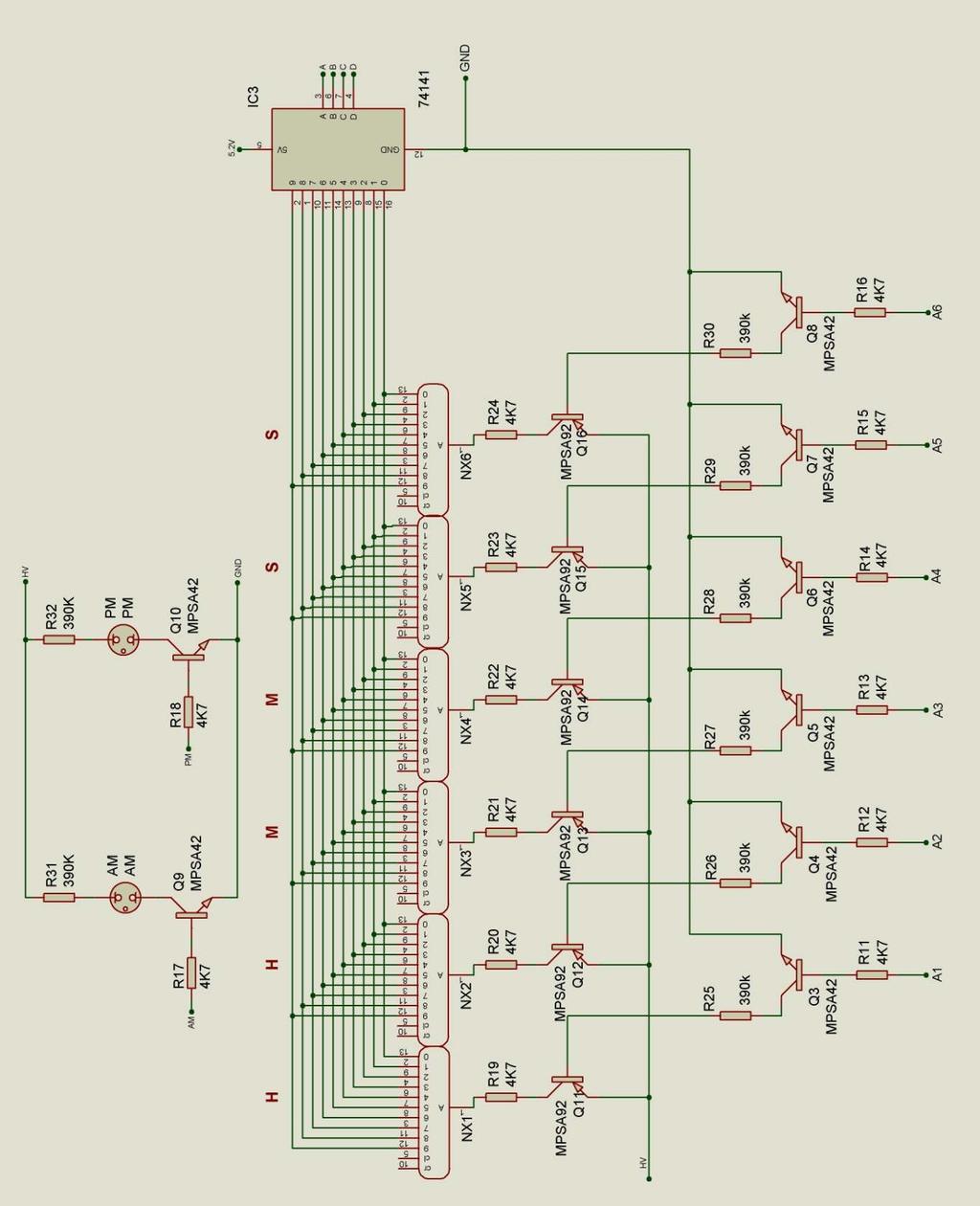
29 9. CIRCUIT DIAGRAM
30 - 30 -
31 10. DIMENSIONED DRAWING
Nixie Clock Type Nixie Maestro
 Assembly Instructions and User Guide Nixie Clock Type Nixie Maestro - 1 - Issue Number Date REVISION HISTORY Reason for Issue 4 01 April 2017 New version with neons for AM / PM 3 10 December 2014 Typing
Assembly Instructions And User Guide. Nixie FunKlock. FunKlock Issue 4 (1 February 2017)
") Assembly Instructions And User Guide Nixie FunKlock - 1 - Issue Number Date REVISION HISTORY 4 1 February 2017 New diode for D2 3 27 December 2013 C7 / C8 error page 15 2 7 November 2013 Errors corrected
Assembly Instructions And User Guide Nixie FunKlock - 1 - Issue Number Date REVISION HISTORY 4 1 February 2017 New diode for D2 3 27 December 2013 C7 / C8 error page 15 2 7 November 2013 Errors corrected
Nixie Clock Type Frank 3'
 Assembly Instructions And User Guide Nixie Clock Type Frank 3' - 1 - REVISION HISTORY Issue Number Date Reason for Issue 4 16 December 2016 New diode for D2 3 12 November 2012 Improved first clock test
Nixie Clock Type Quattro'
 Assembly Instructions And User Guide Nixie Clock Type Quattro' - 1 - Issue Number Date REVISION HISTORY 2 8 Sept 2012 Errors corrected 1 27 July 2012 New document Reason for Issue - 2 - 1.1 Nixie Quattro
Nixie Clock Type IN-8 & NL840 Nixie'
 Assembly Instructions And User Guide Nixie Clock Type IN-8 & NL840 Nixie' - 1 - REVISION HISTORY Issue Number Date 4 15 December 2016 New diode for D2 3 30 August 2014 Typos 2 25 June 2014 Added NL840
Nixie Clock Type Frank 2 Z570M
 Assembly Instructions And User Guide Nixie Clock Type Frank 2 Z570M Software version: 7R PCB Revision: 11 April 09-1 - 1. INTRODUCTION 1.1 About the clock Nixie clock type Frank 2 is a compact design with
SN-Class Nixie Clock Kits
 Assembly Instructions And User Guide SN-Class Nixie Clock Kits - 1 - REVISION HISTORY Issue Date Reason for Issue Number 1 20 November 2017 New document - 2 - 1. INTRODUCTION 1.1 About the How can the
Nixie Clock Type Frank 3
 Assembly Instructions And User Guide Nixie Clock Type Frank 3 Software version: 7R PCB Version: 11 April 09-1 - 1. INTRODUCTION 1.1 About the clock Nixie clock type Frank 3 is a compact design with all
Nixie Clock Type Nixie QTC
 Assembly Instructions And User Guide Nixie Clock Type Nixie QTC - 1 - REVISION HISTORY Issue Number Date Reason for Issue 12 10 September 2015 C6 changed to 33pF 11a 11 December 2014 C5 changed to 10pF.
Nixie Tube Clock Type Marsden
 Assembly Instructions And User Guide Nixie Tube Clock Type Marsden Software version: RTC-1.3 PCB Revision: 16 Aug 10-1 - 1. INTRODUCTION 1.1 About the clock Nixie clock type Marsden is a compact design
Nixie Clock Type Nixie QTC Plus
 Assembly Instructions And User Guide Nixie Clock Type Nixie QTC Plus - 1 - REVISION HISTORY Issue Date Number Draft 1 29 August 2018 New document Reason for Issue - 2 - 1. INTRODUCTION 1.1 Nixie QTC Plus
Assembly Instructions And User Guide. Elite Nixie. Nixie Tube Clock Elite Issue 2 (07 June 2018)
") Assembly Instructions And User Guide Elite Nixie - 1 - REVISION HISTORY Issue Number Date Reason for Issue 2 07 June 2018 Added more NL840 details 1 04 May 2018 New document - 2 - 1. INTRODUCTION Here
Assembly Instructions And User Guide Elite Nixie - 1 - REVISION HISTORY Issue Number Date Reason for Issue 2 07 June 2018 Added more NL840 details 1 04 May 2018 New document - 2 - 1. INTRODUCTION Here
Documentation VFD clock 8 a clock
 Documentation VFD clock 8 a clock This documentation is protected by our copyright. It must not be used for commercial purposes. Congratulations on your purchase of your VFD clock. To guarantee success
Nixie Clock Kit V1.08 Assembly and Operation
 Nixie Clock Kit V1.08 Assembly and Operation Hardware Revision 14.05.2005 Software Version 6.0 Revision 19.04.2006 This document is copyrighted. No parts of this documentation may be used commercially.
7 SEGMENT LED DISPLAY KIT
 ESSENTIAL INFORMATION BUILD INSTRUCTIONS CHECKING YOUR PCB & FAULT-FINDING MECHANICAL DETAILS HOW THE KIT WORKS CREATE YOUR OWN SCORE BOARD WITH THIS 7 SEGMENT LED DISPLAY KIT Version 2.0 Which pages of
Introduction 1. Green status LED, controlled by output signal ST. Sounder, controlled by output signal Q6. Push switch on input D6
 Introduction 1 Welcome to the GENIE microcontroller system! The activity kit allows you to experiment with a wide variety of inputs and outputs... so why not try reading sensors, controlling lights or
Nixie Clock Kit IN-12B color LED backlit Operation Manual Nixie Clock Kit IN-12B V6.0 ( All Right Reserved 2015 )
") Nixie Clock Kit IN-B color LED backlit Operation Manual Nixie Clock Kit IN-B V. ( All Right Reserved ) - - Operation Manual IN-B Nixie Clock Power for your Nixie Clock The clock does not include a wall
Nixie Clock Kit IN-B color LED backlit Operation Manual Nixie Clock Kit IN-B V. ( All Right Reserved ) - - Operation Manual IN-B Nixie Clock Power for your Nixie Clock The clock does not include a wall
N3ZI Digital Dial Manual For kit with Backlit LCD Rev 4.00 Jan 2013 PCB
 N3ZI Digital Dial Manual For kit with Backlit LCD Rev 4.00 Jan 2013 PCB Kit Components Item Qty Designator Part Color/Marking PCB 1 LCD Display 1 LCD 1602 Volt Regulator 1 U1 78L05, Black TO-92 Prescaler
Arduino Nixie Clock Classic Rev4 and Rev5 All In One Modular Rev2
 Arduino Nixie Clock Classic Rev4 and Rev5 All In One Modular Rev2 Operating Instructions Firmware V47 Supported Models: Classic Rev4 Classic Rev5 Modular Rev2 All-In-One NixieClockUserManualV47 About this
Bill of Materials: Super Simple Water Level Control PART NO
 Super Simple Water Level Control PART NO. 2169109 Design a simple water controller in which electrodes are required to sense high and low water levels in a tank. Whenever the water level falls below the
Arduino Nixie Clock Modular Rev3
 Arduino Nixie Clock Modular Rev3 Operating Instructions Firmware V348 Supported Models: Modular Revision 3 NixieClockUserManualV348 About this document This is the user instruction manual for the Nixie
DDS VFO CONSTRUCTION MANUAL. DDS VFO Construction Manual Issue 1.1 Page 1
 DDS VFO CONSTRUCTION MANUAL DDS VFO Construction Manual Issue 1.1 Page 1 Important Please read before starting assembly STATIC PRECAUTION The DDS VFO kit contains the following components which can be
MONO AMPLIFIER KIT ESSENTIAL INFORMATION. Version 2.2 CREATE YOUR OWN SPEAKER DOCK WITH THIS
 ESSENTIAL INFORMATION BUILD INSTRUCTIONS CHECKING YOUR PCB & FAULT-FINDING MECHANICAL DETAILS HOW THE KIT WORKS CREATE YOUR OWN SPEAKER DOCK WITH THIS MONO AMPLIFIER KIT Version 2.2 Build Instructions
ELECTRONIC GAME KIT TEACHING RESOURCES. Version 2.0 BUILD YOUR OWN MEMORY & REACTIONS
 TEACHING RESOURCES SCHEMES OF WORK DEVELOPING A SPECIFICATION COMPONENT FACTSHEETS HOW TO SOLDER GUIDE BUILD YOUR OWN MEMORY & REACTIONS ELECTRONIC GAME KIT Version 2.0 Index of Sheets TEACHING RESOURCES
POINTS POSITION INDICATOR PPI4
 POINTS POSITION INDICATOR PPI4 Monitors the brief positive operating voltage across points motors when they are switched Lights a corresponding led on a control panel to show the last operation of each
VU-1 VU Meter Kit Volume Unit Meter
 VU-1 VU Meter Kit Volume Unit Meter Simplicity Counts, Detail Matters. No part of this document may be reproduced, either mechanically or electronically, posted online on the Internet, in whole or in part,
COLOUR CHANGING USB LAMP KIT
 TEACHING RESOURCES SCHEMES OF WORK DEVELOPING A SPECIFICATION COMPONENT FACTSHEETS HOW TO SOLDER GUIDE SEE AMAZING LIGHTING EFFECTS WITH THIS COLOUR CHANGING USB LAMP KIT Version 2.1 Index of Sheets TEACHING
Christmas LED Snowflake Project
 Christmas LED Snowflake Project Version 1.1 (01/12/2008) The snowflake is a follow-on from my Christmas star project from a few years ago. This year I decided to make a display using only white LEDs, shaped
DIY KIT MHZ 8-DIGIT FREQUENCY METER
 This kit is a stand-alone frequency meter capable of measuring repetitive signals up to a frequency of 50MHz. It has two frequency ranges (15 and 50 MHz) as well as two sampling rates (0.1 and 1 second).
Arduino Nixie Clock Classic Rev4 and Rev5 All In One
 Arduino Nixie Clock Classic Rev4 and Rev5 All In One Operating Instructions Firmware V52 Supported Models: Classic Rev4 Classic Rev5 All-In-One NixieClockUserManualV52 About this document This is the user
QUIZ BUZZER KIT TEACHING RESOURCES. Version 2.0 WHO ANSWERED FIRST? FIND OUT WITH THIS
 TEACHING RESOURCES SCHEMES OF WORK DEVELOPING A SPECIFICATION COMPONENT FACTSHEETS HOW TO SOLDER GUIDE WHO ANSWERED FIRST? FIND OUT WITH THIS QUIZ BUZZER KIT Version 2.0 Index of Sheets TEACHING RESOURCES
TKEY-K16. Touch CW automatic electronic keyer. (No moving parts no contacts) Assembly manual. Last review: March 15, 2018
 Assembly manual. Last review: March 15, 2018") TKEY-K16 Touch CW automatic electronic keyer (No moving parts no contacts) Assembly manual Last review: March 15, 2018 Commands and use manual of the K16 and Updates and news: www.ea3gcy.com Thanks for
TKEY-K16 Touch CW automatic electronic keyer (No moving parts no contacts) Assembly manual Last review: March 15, 2018 Commands and use manual of the K16 and Updates and news: www.ea3gcy.com Thanks for
Tube Cricket Build Guide
 Tube Cricket Build Guide The Tube Cricket is a small-wattage amp that puts out about 1 watt of audio power. With a 12AU7 tube-preamp and a JRC386 power amp, the Tube Cricket gives you great tone in a compact
N3ZI Digital Dial Manual For kit with Serial LCD Rev 3.04 Aug 2012
 N3ZI Digital Dial Manual For kit with Serial LCD Rev 3.04 Aug 2012 Kit properly assembled and configured for Standard Serial LCD (LCD Not yet connected) Kit Components Item Qty Designator Part Color/Marking
Total solder points: 123 Difficulty level: beginner 1. advanced AUDIO ANALYZER K8098. audio gea Give your. . high-tech ILLUSTRATED ASSEMBLY MANUAL
 Total solder points: 123 Difficulty level: beginner 1 2 3 4 5 advanced AUDIO ANALYZER K8098 ra audio gea Give your. look high-tech ILLUSTRATED ASSEMBLY MANUAL H8098IP-1 Features & Specifications Features
ADD AN AUDIO MESSAGE TO YOUR PRODUCT WITH THIS RECORD & PLAYBACK KIT
 ADD AN AUDIO MESSAGE TO YOUR PRODUCT WITH THIS RECORD & PLAYBACK KIT BUILD INSTRUCTIONS Before you start take a look at the Printed Circuit Board (PCB). The components go in the side with the writing on
8 PIN PIC PROGRAMMABLE BOARD (DEVELOPMENT BOARD & PROJECT BOARD)
") ESSENTIAL INFORMATION BUILD INSTRUCTIONS CHECKING YOUR PCB & FAULT-FINDING MECHANICAL DETAILS HOW THE KIT WORKS LEARN ABOUT PROGRAMMING WITH THIS 8 PIN PIC PROGRAMMABLE BOARD (DEVELOPMENT BOARD & PROJECT
ESSENTIAL INFORMATION BUILD INSTRUCTIONS CHECKING YOUR PCB & FAULT-FINDING MECHANICAL DETAILS HOW THE KIT WORKS LEARN ABOUT PROGRAMMING WITH THIS 8 PIN PIC PROGRAMMABLE BOARD (DEVELOPMENT BOARD & PROJECT
Build A Video Switcher
 Build A Video Switcher VIDEOSISTEMAS serviciotecnico@videosistemas.com www.videosistemas.com Reprinted with permission from Electronics Now Magazine September 1997 issue Copyright Gernsback Publications,
Introduction 1. Digital inputs D6 and D7. Battery connects here (red wire to +V, black wire to 0V )
") Introduction 1 Welcome to the magical world of GENIE! The project board is ideal when you want to add intelligence to other design or electronics projects. Simply wire up your inputs and outputs and away
Introduction 1 Welcome to the magical world of GENIE! The project board is ideal when you want to add intelligence to other design or electronics projects. Simply wire up your inputs and outputs and away
16 Stage Bi-Directional LED Sequencer
 16 Stage Bi-Directional LED Sequencer The bi-directional sequencer uses a 4 bit binary up/down counter (CD4516) and two "1 of 8 line decoders" (74HC138 or 74HCT138) to generate the popular "Night Rider"
Mal-2 assembly guide v1.0
 Mal-2 assembly guide v.0 SONIC POTIONS Schematic and BOM The BOM can be found on Google Docs Prepare the PCB Separate the PCBs using some pliers. PCB We start with the lower PCB and assemble it beginning
MAKE AN RGB CONTROL KNOB.
 MAKE AN RGB CONTROL KNOB. This is a knob based colour changing controller that uses a custom programmed microcontroller to pack a lot of features into a small affordable kit. The module can drive up to
LCD Thermometer / Clock S No. 1253
 Installation and Operating Manual LCD Thermometer / Clock S No. 1253 The 3 fold thermometer with crystal clock is purpose build for the mounting in caravans, boats and intervention vehicles. Please read
DTS400B - DZS400BP 3/9/07 10:14 AM Page 1
 DTS400B - DZS400BP 3/9/07 10:14 AM Page 1 18 DTS400B - DZS400BP 3/9/07 10:14 AM Page 3 TABLE OF CONTENTS Section Page Capabilities and Features.......... 1 Installation Instructions............ 2 Instructions
Introduction 1. Green status LED, controlled by output signal ST
 Introduction 1 Welcome to the magical world of GENIE! The project board is ideal when you want to add intelligence to other design or electronics projects. Simply wire up your inputs and outputs and away
Arduino Nixie Clock Modular Rev3
 Arduino Nixie Clock Modular Rev3 Operating Instructions Firmware V352 Supported Models: Modular Revision 3 NixieClockUserManualV352 About this document This is the user instruction manual for the Nixie
DIY Guide - Building Franky v1.1, the SEGA Audio and Videocard for MSX
 DIY Guide - Building Franky v1.1, the SEGA Audio and Videocard for MSX 2015 FRS & MSXpró. Translation by FRS and Supersoniqs. Table of Contents Introduction... 3 Materials needed... 3 Audio volume boost...
RECORD & PLAYBACK KIT
 TEACHING RESOURCES SCHEMES OF WORK DEVELOPING A SPECIFICATION COMPONENT FACTSHEETS HOW TO SOLDER GUIDE ADD AN AUDIO MESSAGE TO YOUR PRODUCT WITH THIS RECORD & PLAYBACK KIT Version 2.1 Index of Sheets TEACHING
Multi-Key v2.4 Multi-Function Amplifier Keying Interface
 Multi-Key v2.4 Multi-Function Amplifier Keying Interface ASSEMBLY & OPERATION INSTRUCTIONS INTRODUCTION The Harbach Electronics, LLC Multi-Key is a multi-function external device designed for the safe
GUIDE TO ASSEMBLY OF ERICA SYNTHS DELAY MODULE
 If you are reading this, most probably, you are about to build Erica Synths DIY DELAY module. The module is 4mm deep, skiff friendly, has solid mechanical construction and doesn t require wiring. Erica
WiFi Time Provider v1 for Arduino Nixie Clock Operating Instructions & Construction Manual
 WiFi Time Provider v1 for Arduino Nixie Clock Operating Instructions & Construction Manual Document V001c Contact Information If you want to get in contact with us, please email to: nixie@protonmail.ch
VU Meter Buffer DIY Kit
 VU Meter Buffer DIY Kit Warning This document is distributed for educational purposes only. This equipment operates at potentially lethal voltages. Only trained, qualified personnel should operate, maintain,
Operating Manual. Basic Control BC16. two-channel for eco moon
 Operating Manual Basic Control BC16 two-channel for eco moon Dear Customer, Thank you for choosing a WALTRON daytime lighting controller. Your daytime lighting controller is a high-quality product that
Timer Modules. MEU11 24 Hour Module, MEU17 7 Day Module (Without Housing)
") Timer Modules MEU11 24 Hour Module, MEU17 7 Day Module (Without Housing) EMU11 24 Hour Module, EMU17 7 Day Module (With Housing Giving panel mounting facility) Installation & Operating Instructions 1 1.
Timer Modules MEU11 24 Hour Module, MEU17 7 Day Module (Without Housing) EMU11 24 Hour Module, EMU17 7 Day Module (With Housing Giving panel mounting facility) Installation & Operating Instructions 1 1.
EPROM pattern generator with "Genlock"
 EPROM pattern generator with "Genlock" This generator uses an EPROM to store several pictures that can then be selected by means of a thumb-wheel switch. Alternatively, if the pictures stored are in a
Analog Style LED Clock
 Analog Style LED Clock Operation and Assembly Manual For use with PCB Rev 2.1 Copyright 2018 All Rights Reserved. Manual version 2.1c, for use with PCB revision 2.1, Software version 2.0.0. The electronic
RSH27 Nixie Tube Socket with LED
 Contents: 1. Applications of the socket 2. Solder instructions of the socket 3. Drawing of the assembled socket 4. Section drawing of the socket with IN-8 tube 5. Drawing and technical data of the tube
FSM User Guide Page 1 of 28
 FSM User Guide Page 1 of 28 Field Strength Meter User Guide and Kit Assembly Instructions PCB V1.1 Important: Always use or print this document in colour as there are references to the colours of components.
Digital Clock. Perry Andrews. A Project By. Based on the PIC16F84A Micro controller. Revision C
 Digital Clock A Project By Perry Andrews Based on the PIC16F84A Micro controller. Revision C 23 rd January 2011 Contents Contents... 2 Introduction... 2 Design and Development... 3 Construction... 7 Conclusion...
Modellbahn Digital Peter Stärz
 Modellbahn Digital Peter Stärz Dresdener Str. 68 D-02977 Hoyerswerda +49 3571 404027 www.firma-staerz.de info@firma-staerz.de 8-fold Track Occupancy Detector for digital systems with two-wire track (e.g.
STX Stairs lighting controller.
 Stairs lighting controller STX-1795 The STX-1795 controller serves for a dynamic control of the lighting of stairs. The lighting is switched on for consecutive steps, upwards or downwards, depending on
Part No. ENC-LAB01 Users Manual Introduction EncoderLAB
 PCA Incremental Encoder Laboratory For Testing and Simulating Incremental Encoder signals Part No. ENC-LAB01 Users Manual The Encoder Laboratory combines into the one housing and updates two separate encoder
XTAL Bank DDS Version 0.02 Sept Preliminary, highly likely to contain numerous errors
 XTAL Bank DDS Version 002 Sept 7 2012 Preliminary, highly likely to contain numerous errors The photo above shows the fully assembled Xtal Bank DDS with 2 DDS modules installed (The kit is normally only
MAIN PCB (The small one) OPEN MAIN BOARD BAG A
 OPEN MAIN BOARD BAG A") THANKS FOR CHOOSING ONE OF OUR KITS! This manual has been written taking into account the common issues that we often find people experience in our workshops. The order in which the components are placed
THANKS FOR CHOOSING ONE OF OUR KITS! This manual has been written taking into account the common issues that we often find people experience in our workshops. The order in which the components are placed
ELECTRONIC GAME KIT ESSENTIAL INFORMATION. Version 2.0 BUILD YOUR OWN MEMORY & REACTIONS
 ESSENTIAL INFORMATION BUILD INSTRUCTIONS CHECKING YOUR PCB & FAULT-FINDING MECHANICAL DETAILS HOW THE KIT WORKS BUILD YOUR OWN MEMORY & REACTIONS ELECTRONIC GAME KIT Version 2.0 Build Instructions Before
Arduino IN-14 Nixie Clock v42 All-In-One Clock Operating Instructions & Construction Manual
 Arduino IN-14 Nixie Clock v42 All-In-One Clock Operating Instructions & Construction Manual NixieClockIN14InstructionManualRev2V42 Contact Information If you want to get in contact with us, please email
Digital Economy Seven Programmer
 Digital Economy Seven Programmer Model: TRTD7N White Installation & Operating Instructions 1. General Information These instructions should be read carefully and retained for further reference and maintenance.
16 Amp Electronic 24 Hour/7 Day Time Controller
 16 Amp Electronic 24 Hour/7 Day Time Controller Model: ELU56 Installation & Operating Instructions 1 1. General Information These instructions should be read carefully and retained for further reference
Installing The PK-AM keyer and. from Jackson Harbor Press Operating: A Morse code keyer chip with pot speed control
 Installing The PK-AM keyer and from Jackson Harbor Press Operating: A Morse code keyer chip with pot speed control The PK-AM keyer is a modification for the PK-AM kit, it changes the AM transmitter to
NETWORK COMPASS USER MANUAL CONTENTS
 CONTENTS NETWORK COMPASS USER MANUAL GENERAL INTRODUCTION TO B&G NETWORK...2 INTRODUCTION TO NETWORK COMPASS...3 COMPASS DISPLAY UNIT...4 EXAMPLE SYSTEMS USING NETWORK COMPASS...4 INITIAL POWER-UP...5
Thank you for purchasing this product. If installing for someone else, please ensure that the instructions are handed to the householder.
 Instruction Manual TPSE201 (181422) - BOSS TM Universal Programmer TPSE101 (569565) - BOSS TM Universal Timeswitch Thank you for purchasing this product. If installing for someone else, please ensure that
ULTRA-VANSTAT WIRELESS PROGRAMMABLE THERMOSTAT FOR CARAVANS
 ULTRA-VANSTAT WIRELESS PROGRAMMABLE THERMOSTAT FOR CARAVANS NOT SUPPLIED PROGRAMMER / TRANSMITTER RECEIVER THIS DOMESTIC STYLE WIRELESS 7 DAY PROGRAMMABLE HEATER CONTROL REPLACES THE TRUMA ULTRAHEAT SWITCH
Parts Checklist - Please note there is no resistor R3. Diodes, LED and transistors are polarized see construction stages
 Xtal Check Kit build Read me first! -------- UPDATED GUIDE------ September 12, 2018--------- The following steps are designed to get your Xtal check kit built and operational. This is a good beginner s
SceneStyle2 User Guide
 SceneStyle2 User Guide Mode Lighting (UK) Limited. The Maltings, 63 High Street, Ware, Hertfordshire, SG12 9AD, UNITED KINGDOM. Telephone: +44 (0) 1920 462121 Facsimile: +44 (0) 1920 466881 e-mail: website:
Arduino Modular IN-14 Nixie Clock Rev2 V45 All-In-One Modular Clock Operating Instructions & Construction Manual
 Arduino Modular IN-14 Nixie Clock Rev2 V45 All-In-One Modular Clock Operating Instructions & Construction Manual NixieClockModularInstructionManualRev2V45 Contact Information If you want to get in contact
Industriefunkuhren. Technical Manual. IRIG-B Generator-Module for analogue / digital Signals of Type: IRIG-B / IEEE C / AFNOR NF S87-500
 Industriefunkuhren Technical Manual IRIG-B Generator-Module for analogue / digital Signals of Type: IRIG-B / IEEE C37.118 / AFNOR NF S87-500 Module 7628 ENGLISH Version: 02.01-06.03.2013 2 / 20 7628 IRIG-B
DL-1A. RF dummy load - 50Ω 20W. Assembly manual. Last update: May 1, Thank you for constructing the DL-1A dummy load kit
 DL-1A RF dummy load - 50Ω 20W Assembly manual Last update: May 1, 2016 ea3gcy@gmail.com Updates and news at: www.qsl.net/ea3gcy Thank you for constructing the DL-1A dummy load kit Have fun assembling it
While the parts are already inventoried at the factory, please verify the inventory check as you go:
 Thank you for purchasing the kit for building the WJ9J DTMF controller. After building, you should read the document on operation (WJ9JDTMFControllerV5.pdf) in order to use. This is also in the link in
Total solder points: 117 Difficulty level: beginner advanced. RGB Controller K8088 ILLUSTRATED ASSEMBLY MANUAL
 Total solder points: 117 Difficulty level: beginner 1 2 3 4 5 advanced RGB Controller K8088 Control incandescent bulbs, LEDs, common anode led strips, etc... ILLUSTRATED ASSEMBLY MANUAL H8088IP-1 Features
Reaction Game Kit MitchElectronics 2019
 Reaction Game Kit MitchElectronics 2019 www.mitchelectronics.co.uk CONTENTS Schematic 3 How It Works 4 Materials 6 Construction 8 Important Information 9 Page 2 SCHEMATIC Page 3 SCHEMATIC EXPLANATION The
Bill of Materials: Magic Color PART NO
 Magic Color PART NO. 2193838 Magic color is a guessing game. With this game you can surprise your friends and leave them with amazement, how the game guesses what they have in their minds. Only two selections
SCS318. User Instructions. SCS318 comprising of SCS317 7 Day Wireless Programmable Room Thermostat and SSR303 Receiver
 SCS318 User Instructions SCS318 comprising of SCS317 7 Day Wireless Programmable Room Thermostat and SSR303 Receiver Programmable room thermostats are widely recognised as one of the best ways in which
FN:4181NX_M1.DOC MC4181NX MASTER CLOCK MC4181NX
 FN:4181NX_M1.DOC MC4181NX MASTER CLOCK MC4181NX TABLE OF CONTENTS 1.0 INTRODUCTION 2.0 SPECIFICATIONS 3.0 INSTALLATION 4.0 GETTING STARTED 4.1 The Auto-Prompt Display 4.2 The Cursor, Entering Data 4.3
Dust Sensor using GP Y
 Dust Sensor using GP Y Dust sensors detect fine dust ( aerosol ) floating in the air. They are used to determine air quality indoor and outdoor. Limits of the GP2Y10 The GP2Y10 sensor was developed to
TECHNOLOGY WILL SAVE US: THE LUMIPHONE
 TECHNOLOGY WILL SAVE US: THE LUMIPHONE This is a step-by-step guide to soldering your own Lumiphone. The equipment you should have at your station: goggles, soldering mat, soldering Iron, solder and side
Master Time Clock MTC Users Manual
 Master Time Clock MTC-6000 Users Manual Midwest Time Control Phone (972)987-4408 Toll Free (888)713-0373 FAX (877)720-9291 www.midwest-time.com sales@midwest-time.com TABLE OF CONTENTS TOPIC PAGE GENERAL
NewScope-7A Operating Manual
 2016 SIMMCONN Labs, LLC All rights reserved NewScope-7A Operating Manual Preliminary May 13, 2017 NewScope-7A Operating Manual 1 Introduction... 3 1.1 Kit compatibility... 3 2 Initial Inspection... 3 3
Azatrax Model Railroad Track Signal Control - Single Track
 Installation Guide Azatrax Model Railroad Track Signal Control - Single Track TS2 What it is: The TS2 operates one or two trackside block signals (one in each direction) on one track to simulate the block
Operating Instructions
 CNTX Contrast sensor Operating Instructions CAUTIONS AND WARNINGS SET-UP DISTANCE ADJUSTMENT: As a general rule, the sensor should be fixed at a 15 to 20 angle from directly perpendicular to the target
Analog/digital watch Multi frequency reception, 4 digit LCD, 3 hands. Preliminary Specification
 Analog/digital watch Multi frequency reception, 4 digit LCD, 3 hands Preliminary Specification Supplier: Asia Limited Unit 125, 1/F., Liven House, 61-63 King Yip Street, Kwun Tong, HK SAR Issued on: 20.12.2005
OPERATION NOTES FOR PSIDEX AUDIO PGP-1A PRE-AMPLIFIER DESCRIPTION INSTALLATION
 OPERATION NOTES FOR PSIDEX AUDIO PGP-1A PRE-AMPLIFIER DESCRIPTION The Psidex Audio Laboratory PGP- 1A is a vacuum tube based microphone preamp and program line amplifier designed to provide solid, robust
SBL /SBLG Series Wireless Clock
 Installation Manual V8.3 SBL /SBLG Series Wireless Clock Current as of August 2018 The Sapling Company, Inc. SBL and SBLG Series Wireless Clocks Table of Contents Table of Contents 2 Important Safety Instructions
Instruction Manual. Universal Flow Controller Model 261 / 261-EC-01
 Universal Flow Controller Model 261 / 261-EC-01 Instruction Manual Type ARS 261-EC 01 Art.-no: 82212264 Table of Contents 1. Safety Instructions 2. Product ID - Dimensions 3. Function Description 4. Installation
Instructions for Use P.154-UP (9/4) P.155-UP (9/8) P.150-UP-12 (9/12) P.150-UP-16 (9/16)
 P.155-UP (9/8) P.150-UP-12 (9/12) P.150-UP-16 (9/16)") Satellite multiswitch Instructions for Use P.154-UP (9/4) P.155-UP (9/8) P.150-UP-12 (9/12) P.150-UP-16 (9/16) EMP-CENTAURI is a registered trademark Dear Customer, Thank you for buying the EMP-Centauri
Satellite multiswitch Instructions for Use P.154-UP (9/4) P.155-UP (9/8) P.150-UP-12 (9/12) P.150-UP-16 (9/16) EMP-CENTAURI is a registered trademark Dear Customer, Thank you for buying the EMP-Centauri
DLP200M 2 Relay Module for Heating and Cooling Plants
 Product Sheet TH6.24 Thermostat Type DLP200M DLP200M 2 Relay Module for Heating and Cooling Plants The DLP 200 M is a relay module for activation of loads (namely thermal actuators or circulators) in wireless
7 Day Digital Light Switch with Optional Dusk Start
 7 Day Digital Light Switch with Optional Dusk Start Model: ZV700B Installation & Operating Instructions 1 1. General Information These instructions should be read carefully and retained for further reference
AXE101 PICAXE-08M2 Cyberpet Kit
 AXE101 PICAXE-08M2 Cyberpet Kit The Cyberpet project uses a PICAXE-08M2 microcontroller with two LEDs as the pets eyes and a piezo sounder as a voice for the pet. The project also uses a switch so that
Fixed Audio Output for the K2 Don Wilhelm (W3FPR) & Tom Hammond (NØSS) v August 2009
 & Tom Hammond (NØSS) v August 2009") Fixed Audio Output for the K2 Don Wilhelm (W3FPR) & Tom Hammond (NØSS) v. 2.1 06 August 2009 I have had several requests to provide a fixed audio output from the K2. After looking at the circuits that
Fixed Audio Output for the K2 Don Wilhelm (W3FPR) & Tom Hammond (NØSS) v. 2.1 06 August 2009 I have had several requests to provide a fixed audio output from the K2. After looking at the circuits that
Aspect 2 Circuit Digital Scene Control
 Aspect 2 Circuit Digital Scene Control S p e c i f i c a t i o n 2 circuits of trailing edge dimming 500W total between the two circuits Both circuits feature independent overload, short-circuit and open-circuit
SPX-5600 Series. Operations Manual. Suprex Reader Extender - RF Wireless Interface SPX-5600MAN. Page 1 of 20
 SPX-5600 Series Operations Manual Suprex Reader Extender - RF Wireless Interface SPX-5600MAN Page 1 of 20 SPX-5600 Series: Cypress Suprex SPX-5600 Series This manual covers the operation and setup of the