Nixie Clock Type Nixie QTC
|
|
|
- Stanley O’Neal’
- 6 years ago
- Views:
Transcription

1 Assembly Instructions And User Guide Nixie Clock Type Nixie QTC - 1 -
2 REVISION HISTORY Issue Number Date Reason for Issue September 2015 C6 changed to 33pF 11a 11 December 2014 C5 changed to 10pF. Typing errors corrected October 2014 New PCB 30 September a 21 March 2014 Errors corrected March 2014 New tube types added and code configuration procedure 9 03 April 2013 Troubleshooting connections chart added ZM1177 tube procedure clarified 8a 09 September 2013 Improved IN14 cell details 8 21 October 2012 WWVB No Longer supported 7 8 October 2012 ZM1177 Tube details added 6 5 August 2012 Component designation errors corrected 5 27 July 2012 New PCB date 5 July June st review 3 29 May 2012 Errors in component listing corrected 2 22 May 2012 Anode resistors corrected to 10KΩ 1 20 May 2012 New document - 2 -
3 1. INTRODUCTION 1.1 What is Nixie QTC? Nixie QTC takes a new path for Nixie Clocks for mid-sized solder-in tubes. Learning from our past experiences of thousands of kits sold, we recognise a major customer concern and possibly the biggest drawback with solder-in tubes: They are soldered in! Previously, a failed tube always meant a treacherous operation to delicately remove the tube whilst trying to preserve all traces intact. Whilst this was certainly possible, It was never easy, and made it uncomfortable to give a Nixe Clock as a gift in case a tube ever failed. With Nixie QTC ( Quick Tube Change ), each tube is soldered only to its own mini tube cell PCB. A tube can be changed in minutes with no danger to the main PCB. The small addition in cost is dwarfed by the huge advantage this gives. A single main board is capable of driving tens of different types of solder-in Nixie Tube. You can even completely change the tube type of your clock by installing new tube cells and tubes. Software But at such a major change in direction, we have also taken the opportunity to build on the solid software foundations of the predecessor Frank 2 format and add some truly useful and productive software features. As before, the main controller is the PIC16F1936 running at 16Mhz. The code is programmed entirely in the C programming language. Drive Mode The former K155ID1 / nixie driver IC is now replaced by a modern HV5812 High Voltage Driver IC by Supertex. With 20 outputs, it is able to drive the six Nixie Tubes in a very comfortable and low noise 3X2 multiplex. GPS Time Synchronisation A radical new clock design deserves a new and exciting GPS receiver module for those that demand the best timekeeping. And, with a groundbreaking price for a GPS receiver, a fully featured Nixie Clock with GPS synchronsation is now within the price range of most buyers
4 1.2 Nixie QTC - Features Nixie clock type Nixie QTC has the following features: - Hours, Minutes and Seconds display - 12 or 24 hour modes - Uses a Quartz Crystal Oscillator as the timebase - Programmable leading zero blanking - Date display in either DD.MM.YY or MM.DD.YY or YY.MM.DD format - Programmable date display each minute - Scrolling display of date or standard display - Alarm, with programmable snooze period - Optional DCF / MSF / GPS synchronisation with status indicator LED - Dedicated DST button to switch between DST and standard time - Supercapacitor backup. Keeps time during short power outages - Simple time setting using two buttons - Programmable leading zero blanking - Five programmable neon colon settings (Flashing AM/PM indication, illuminated AM/PM indication, both flashing, both on, both off) - Seconds can be reset to zero to precisely the set time - Programmable night mode - blanked or dimmed display to save tubes or prevent sleep disturbance - Rear Indicator LEDs dim at night to prevent sleep disturbance - Weekday aware Master Blank function to turn off HV/ tubes and LEDs on weekends or during working hours - Separate modes for colon neons during night mode - Standard or fading change of digits - Standard, fading, or fading with scrollback display modes - Slot Machine Cathode poisoning prevention routine - Programmable RGB tube lighting select YOUR favourite colour palette colours possible. Have a different colour or your choosing every hour, or autochanging colours. - Not AC frequency dependent works in all countries - All user preferences stored to non-volatile memory - 4 -
5 1.3 Tubes Supported Each tube is soldered to a mini PCB 'Cell', making tubes easily changeable. Through the use of 2 different cell types, and 3 different configurations of the microcontroller, it is possible for the kit to drive a wide range of solder-in tubes as detailed in the table below. There are detailed and specific instructions for mounting each type of tube, in sections 5.1 to 5.8 of this manual. Tube types Cell type Code Section Configuration IN-14 IN-14 A 5.1 IN-8-2, ZM1177 IN-8-2 A 5.2 Z570M, Z5700M, Z573M, Z5730M, IN-8-2 A 5.3 Z574M, Z5740M, GN-9A, B570M, TAF1317A, TAU7030, F9080B, F9080BA, TAF1093A, ZM1080, ZM1082, ZM1134, ZM1135, ZM1136, ZM1136A, ZM1136L, ZM1136R, ZM1138A, ZM1138L, ZM1138R GNP-17A IN-8-2 A 5.4 GNP-7A, GNP-7AH IN-8-2 A 5.5 ZM1210, ZM1212 IN-8-2 B 5.6 IN-16 IN-14 C 5.7 CD66, ZM1240, ZM1242, XN11, XN12 IN-8-2 A
6 1.4 SAFETY DANGER: The clock pcb includes a switched-mode voltage booster circuit. This generates nominally 170 Volts DC. Assembly may only be undertaken by individuals who are suitably qualified and experienced in electronics assembly, and are familiar with safe procedures for working with high voltages. If in doubt, refer to a suitably qualified engineer before proceeding. The voltages generated by this circuit can give a potentially LETHAL ELECTRIC SHOCK. DISCLAIMER: This product is supplied as a kit of parts, intended only for suitably qualified electronic engineers, who are suitably qualified and experienced in electronics assembly, and are familiar with safe procedures for working with high voltages. The supplier, his agents or associates accept no liability for any damage, injury or death arising from the use of this kit of parts. This is not a finished product, and the person assembling the kit is responsible for ensuring that the finished product complies with any applicable local regulations governing electrical equipment, eg. UL, CE, VDE
.")
7 2. TOOLS AND EQUIPMENT REQUIRED 2.1 Tools required to assemble the PCB. The following tools will be required to assemble the PCB: - Soldering iron with a small tip (1-2 mm). - Wire cutters to trim the excess component leads after soldering. (TIP: A small pair of nail clippers works very well for this function). - Wire strippers (TIP: A small pair of scissors is quite suitable). - Multimeter for voltage tests and for identifying the resistors. 2.2 Materials you will need. Solder lead / tin solder is highly recommended. USE LEAD/ TIN SOLDER!. Lead free solder, as now required to be used in commercial products in Europe, has a much higher melting point and can be very hard to work with. Desoldering wick (braid) can be useful if you accidentally create solder bridges between adjacent solder joints. 2.3 Other items you will need. The clock kit does not include a power adapter. The following type of adapter should be obtained and used with the kit: Output 12V DC regulated, minimum power output capability of 500 ma Output plug: 2.1mm pin, centre positive. A suitable adapter is shown below: - 7 -
8 3. LIST OF COMPONENTS 3.1 Table of Components Driver Board Circuit Designation Part Description Resistors R1 4.7 KΩ, ¼ Watt R2 390 KΩ, ¼ Watt R3 4.7 KΩ, ¼ Watt R4 390 KΩ, ¼ Watt R5 4.7 KΩ, ¼ Watt R6 - R Ω, ¼ Watt R12 R KΩ, ¼ Watt R15 R KΩ, ¼ Watt R18 R20 10 KΩ, ¼ Watt R21 R KΩ, ¼ Watt R29, R KΩ, ¼ Watt R31 R Ω, ¼ Watt Capacitors C1, C2 220uF Electrolytic C3 1uF, 250V, C4 220uF, 16-25V, Electrolytic C5 10pF Ceramic C6 33pF Ceramic C7 100nF Ceramic C8 0.1F or 0.22F C9, C10 100nF Transistors Q1 IRFD220 MOSFET Q2 Q4 2N7000 MOSFET Q5 Q7 MPSA42 Q8 Q10 MPSA92 Q11 Q13 MPSA42 Diodes D1 D3 1N5819 D4 62V zener D5 UF4004 D6 5mm Yellow LED D7 5mm Green LED D8 5mm Yellow LED D9 62V zener D10 D15 RGB 5mm LED, common anode Integrated Circuits IC1 LM2576 5V voltage regulator IC2 PIC16F bit microcontroller IC3 HV5812 Miscellaneous L1, L2 100uH inductor AM, PM 4mm wire ended neon lamp ALARM, SET, ADJ, DST Miniature push button IC2 Socket 28 Way narrow IC socket for IC2 IC3 Socket PLCC28 IC socket for IC3-8 -
9 J1 GPS / RFT LS1 FUSE Insulation NX1 NX6 X1 2.1mm PCB power socket Surface mount 3.5mm jack socket Piezo sounder 500mA fuse Clear insulation for neons 2X6 way 0.1 header plug KHz watch crystal - 9 -
10 3.2 Parts list / Packing Sheet - Component Bag Part Description Quantity Resistors 270 Ω, ¼ Watt KΩ, ¼ Watt KΩ, ¼ Watt KΩ, ¼ Watt 7 Capacitors 10pF, Ceramic 1 33pF, Ceramic 1 100nF, Ceramic 3 1uF, 250V, Electrolytic 1 220uF, 16-25V, Electrolytic 3 0.1F or 0.22F 1 Transistors IRFD220 MOSFET 1 MPSA42 6 MPSA92 3 2N Diodes 1N UF4004 fast recovery diode 1 62V Zener diode 2 5mm Green LED 1 5mm Yellow LED 2 5mm RGB LED 6 Integrated Circuits LM2576 5V voltage regulator 1 PIC16F bit microcontroller 1 HV Miscellaneous 100uH inductor 2 4mm wire ended neon lamp 2 Miniature push button 4 28 way narrow IC Socket for IC2 1 PLCC28 IC Socket for IC mm PCB power socket 1 Surface mount 3.5mm jack socket 1 Piezo sounder 1 500mA fuse 1 Clear insulation for neons 1 2X6 way 0.1 header plug 6 2X6 way 0.1 header socket KHz watch crystal

11 It is recommended that the kit is checked against the list above, to ensure all parts are present before commencing assembly. Don t be alarmed if there are some extra components, as some component bags are shared between different kit types. The resistors used in the kit are 1% tolerance metal film. They are marked with 4 coloured bands to identify the value. However it is sometimes unclear in which direction the bands should be read. Therefore, we recommend that the resistors be identified with a multimeter. Please note the fuse will look like the picture below. It can easily be confused for a capacitor. It is a self-resetting fuse

 L2 (100uH Inductor) C1, C2 (220uF) Start by installing D1-D4.")
12 4. ASSEMBLY OF THE PCB DUE TO PRODUCT DEVELOPMENT AND IMPROVEMENTS, YOUR PCB MAY NOT LOOK EXACTLY LIKE THE ONE PICTURED. 4.1 Low Voltage Power components: J1, FUSE D1-D3 (1N5819) D4 (62V Zener Diode) IC1 (LM2576) L2 (100uH Inductor) C1, C2 (220uF) Start by installing D1-D4. Align the band on the components with the band marked on the PCB


13 After placement, IC1 can be placed and bent over these diodes to reduce the height of the assembled PCB. Continue to mount C1, C2, J1 and FUSE. C1 and C2 are polarized. The longer lead goes in the hole marked Testing Low Voltage Power Supply. Identify the test GND, 5V and HV test points as shown below. Plug in the power supply, and then test using a DC voltmeter: Touch the black probe on the GND test point and the red probe on the 5V test point. The voltage should measure between 5.6 and 5.9 Volts. If not, disconnect power and check your work. Do not proceed with the assembly until the error is corrected. Once the test is completed, disconnect the power
 R2, R4 (390 KΩ) C3 (1uF) C4 (220uF) Q1 (IRFD220) L1 (100uH Inductor) D5 (UF4004)")
14 4.3 High Voltage Generator components. Socket for IC2 R1, R3 (4.7 KΩ) R2, R4 (390 KΩ) C3 (1uF) C4 (220uF) Q1 (IRFD220) L1 (100uH Inductor) D5 (UF4004) D9 (62V Zener diode)


15 All the resistors on the board need to be mounted upright to save space. The leads need to be formed as shown below. Bend the leads of each resistor as shown and solder in to the correct postion, making sure the component body is as close to the board as possible. Take care that the notched end of the IC socket is at the end shown. Also the MOSFET needs to be placed with the two joined pins at the position shown below. Ensure that the (-) light stripes on C3 and C4 are facing inwards towards each other as shown below

16 4.4 High Voltage Generator Test. - Refer to the warnings on page 5 - Insert IC2 into its socket. Orient the notch on the IC with the notch on the IC socket and the PCB marking. - Power up the PCB, and using the GND and HV test points, measure the high voltage generated using a voltmeter on DC setting. It should be between 165 and 175 Volts. If this is in order, disconnect the power supply. 4.5 C5 (10pF) C6 (33pF) X1 (32.768KHz Crystal) C7, C9, C10 (100nF)

 R18 - R20 (10 KΩ)")
 4.")
17 4.6 R6 - R11 (270 Ω) R5, R12 R14, R21 R28 (4.7 KΩ) R15 - R17, R29, R30 (390 KΩ) R18 - R20 (10 KΩ) 4.7 Q5, Q6, Q7, Q11, Q12, Q13 (MPSA42) 4.8 Q8, Q9, Q10 (MPSA92)


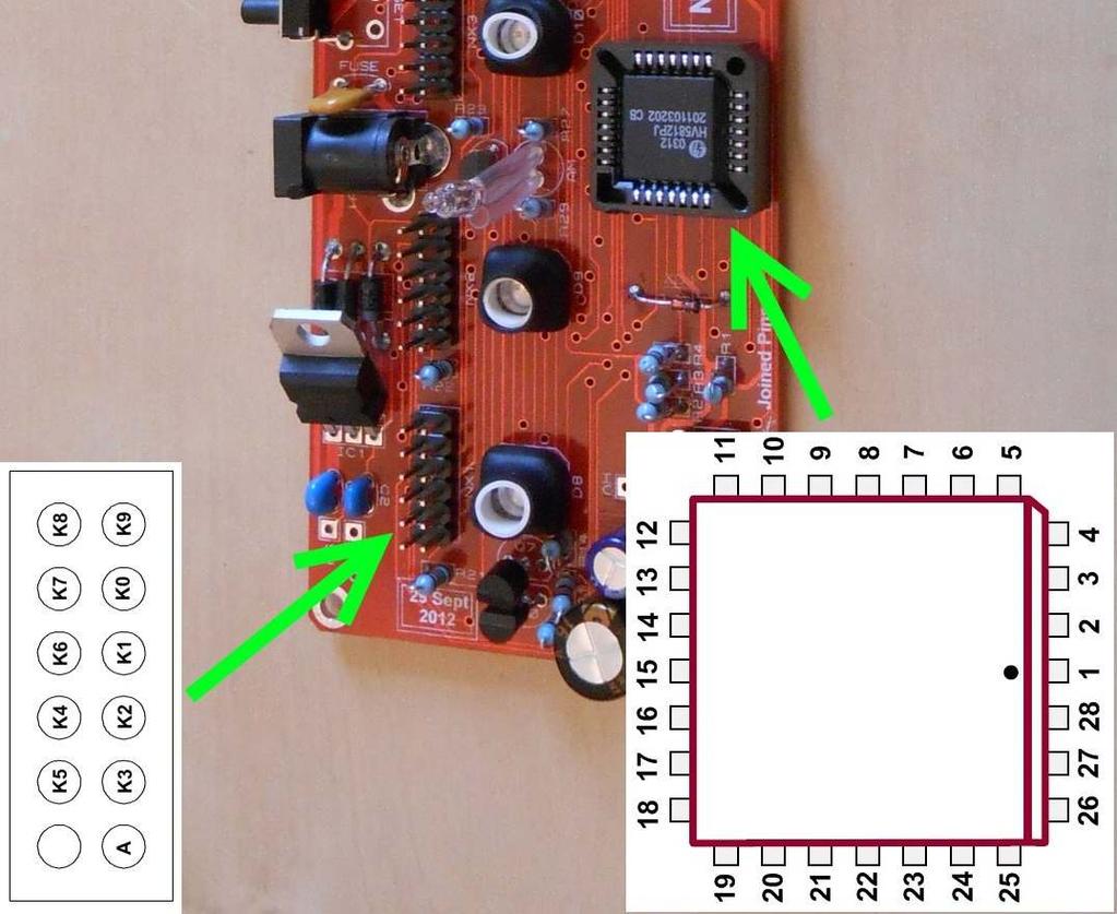
18 This is how the PCB should look now: 4.9 Socket for IC3 Align the notch on one corner of the socket with the marking on the PCB. Be careful not to force in the socket if all pins are not aligned. Ensure all pins are fully pushed through the holes before soldering in place NX1 NX6 (6X2 way male pin header)
 To solder the GPS / RFT connector: First wet one pad on the PCB with solder.")

19 Ensure the connectors are soldered very close to the PCB GPS/ RFT Connector LS1 (Piezo Buzzer) C8 (0.1F) To solder the GPS / RFT connector: First wet one pad on the PCB with solder. Then place the connector in position and re-touch the pad with the soldering iron. This will anchor the component and then you can solder the remaining pads. Ensure the arrows on C8 are aligned with the corresponding arrows on the PCB


20 4.12 D7 (5mm Green LED) D6, D8 (5mm Yellow LED) SET, ADJ, ALARM, DST (Push switches) First, bend the leads of the LEDs as shown below, paying attention to the longer (+) lead being on the left hand side. Then solder in place with the body of the LED just touching the PCB. Then place and solder the 4 push button switches: 4.13 AM, PM Neon Indicators It is a good idea to install these components at the very end of the assembly, when you have a better idea of a suitable height that will look perfect with your design of case. So, do not install them now but remember to install them some time later! Use small pieces of the clear insulation supplied to prevent shorts on the leads

21 5. ASSEMBLING THE NIXIE TUBE CELLS PLEASE REFER TO THE APPROPRIATE SECTION FOR YOUR NIXIE TUBE TYPE. 5.1 IN-14 Nixie Tubes. Tube cell type: IN-14 Code configuration: A NOTE: IN-14 Cells supplied after August 2013 will not have the two holes either side of the anode. Simply clip off the two leads either side of the anode. To facilitate easy insertion of the flying leads into the small holes, it helps enormously to trim the flying leads with a pair of scissors as shown below. Start by identifying the anode lead at the back of the tube. It has a white coating where it enters the glass. Then, working around the tube, cut each sucessive lead approx 2mm shorter than the previous one. This will allow you to feed each lead in in turn

. The tube cell is now complete.")
22 Referring to the picture below, identify the anode pad on the tube cell PCB. The tube is inserted from the side with no white markings: Now you can insert and solder in the tube. Pay attention that the tube sits squarely on the PCB. Then solder on the connector (which may be in two pieces). The tube cell is now complete. Repeat for the other 5 tubes. Then move on to step

23 5.2 IN-8-2 and ZM1177 Nixie Tubes. Tube cell type: IN-8-2 Code configuration: A These tubes have a gap between leads at the back of the tube. The ZM1177 in fact has a small stub of a lead that is trimmed at manufacture. This helps identify the back of the tube, as well as being opposite to the viewing face of the tube. The ZM1177 also has a gap between tubes near the front. Disregard this gap - the wires at either side will fit into adjacent holes on the PCB. Remember: 12 wires into 12 holes. To facilitate easy insertion of the flying leads into the small holes, it helps enormously to trim the flying leads with a pair of scissors as shown below. Start at one of the leads at the back of the tube. Then, working around the tube, cut each sucessive lead approx 2mm shorter than the previous one. This will allow you to feed each lead in in turn. Now you can insert and solder in the tube. Insert the 12 leads into the 12 holes. Insert from the side of the PCB with no markings. Pay attention that the tube sits squarely on the PCB. Ensure the tube is facing perfectly forwards before soldering - you may need to twist it a little. Note that there is one hole that is unused - simply trim off this lead without soldering. Then solder on the connector (which may be in two pieces)

24 The tube cell is now complete. Repeat for the other 5 tubes. Then move on to step


25 5.3 Z570M, Z573M, ZM1080, ZM1082, GN9A, ZM1136 Nixie Tubes. Tube cell type: IN-8-2 Code configuration: A It is necessary to clip off two of the Z570M and equivalent tube leads: Clip off the two leads as shown below: This is how the tube will look after removing the leads: To facilitate easy insertion of the flying leads into the PCB holes, it helps enormously to trim the remaining flying leads with a pair of scissors as shown below. Start at one of the leads at the back of the tube


26 Then, working around the tube, cut each sucessive lead approx 2mm shorter than the previous one. This will allow you to feed each lead in in turn. Now you can insert and solder in the tube. There are 11 leads on the trimmed tube and 12 pads on the PCB. One of the pads on the PCB is unconnected. DO NOT INSERT A LEAD INTO THIS HOLE:

27 Insert from the side of the PCB with no markings. Pay attention that the tube sits squarely on the PCB. Then solder on the connector. The tube cell is now complete. Repeat for the other 5 tubes. Then move on to step


28 5.4 GNP-17A Nixie Tubes. Tube cell type: IN-8-2 Code configuration: A These tubes have 2 leads that need to be removed as shown below. Use the gap to correctly orient the tube: To facilitate easy insertion of the flying leads into the small holes, it helps enormously to trim the flying leads with a pair of scissors. Start at one of the leads at the back of the tube. Then, working around the tube, cut each sucessive lead approx 2mm shorter than the previous one. This will allow you to feed each lead in in turn. Now you can insert and solder in the tube. Insert the 11 leads into the 11 holes with pads as shown below. Insert from the side of the PCB with no markings

29 Pay attention that the tube sits squarely on the PCB. Ensure the tube is facing perfectly forwards before soldering - you may need to twist it a little. Then solder on the connector. The tube cell is now complete. Repeat for the other 5 tubes. Then move on to step

30 5.5 GNP-7A and GNP-7AH Nixie Tubes. Tube cell type: IN-8-2 Code configuration: A These tubes have 2 leads that need to be removed as shown below. Use the gap to correctly orient the tube: To facilitate easy insertion of the flying leads into the small holes, it helps enormously to trim the flying leads with a pair of scissors. Start at one of the leads at the back of the tube. Then, working around the tube, cut each sucessive lead approx 2mm shorter than the previous one. This will allow you to feed each lead in in turn. Now you can insert and solder in the tube. Insert the 11 leads into the 11 holes with pads as shown below. Insert from the side of the PCB with no markings

31 Pay attention that the tube sits squarely on the PCB. Ensure the tube is facing perfectly forwards before soldering - you may need to twist it a little. Then solder on the connector. The tube cell is now complete. Repeat for the other 5 tubes. Then move on to step

32 5.6 ZM1210 and ZM1212 Nixie Tubes. Tube cell type: IN-8-2 Code configuration: B These tubes have 2 leads that need to be removed as shown below. Use the gap to correctly orient the tube: To facilitate easy insertion of the flying leads into the small holes, it helps enormously to trim the flying leads with a pair of scissors. Start at one of the leads at the back of the tube. Then, working around the tube, cut each sucessive lead approx 2mm shorter than the previous one. This will allow you to feed each lead in in turn. Now you can insert and solder in the tube. Insert the 11 leads into the 11 holes with pads as shown below. Insert from the side of the PCB with no markings

33 Pay attention that the tube sits squarely on the PCB. Ensure the tube is facing perfectly forwards before soldering - you may need to twist it a little. Then solder on the connector. The tube cell is now complete. Repeat for the other 5 tubes. Then move on to step


34 5.7 IN-16 Nixie Tubes. Tube cell type: IN-14 Code configuration: C These tubes have 2 leads that need to be removed as shown below. Use the back of the tube to correctly orient the tube: To facilitate easy insertion of the flying leads into the small holes, it helps enormously to trim the flying leads with a pair of scissors. Start at one of the leads at the back of the tube. Then, working around the tube, cut each sucessive lead approx 2mm shorter than the previous one. This will allow you to feed each lead in in turn. Now you can insert and solder in the tube. Insert the 11 leads into the 11 holes with pads as shown below. Insert from the side of the PCB with no markings

35 Pay attention that the tube sits squarely on the PCB. Ensure the tube is facing perfectly forwards before soldering - you may need to twist it a little. Then solder on the connector. The tube cell is now complete. Repeat for the other 5 tubes. Then move on to step

36 5.8 CD66, ZM1242, ZM1240, XN11 and XN12 Nixie Tubes. Tube cell type: IN-8-2 Code configuration: A CD66, ZM1240 and ZM1242: These tubes have 1 lead at the very back of the tube that needs to be removed. Ensure you only clip the lead at the very back of the tube, this will leave you with 11 leads remaining and a gap at the back of the tube. Proceed as for XN11 and XN12 below. XN11 and XN12: These tubes have 11 leads and a gap at the very back of the tube. To facilitate easy insertion of the flying leads into the small holes, it helps enormously to trim the flying leads with a pair of scissors. Start at one of the leads at the back of the tube. Then, working around the tube, cut each sucessive lead approx 2mm shorter than the previous one. This will allow you to feed each lead in in turn. Now you can insert and solder in the tube. Insert the 11 leads into the 11 holes with pads as shown below. Insert from the side of the PCB with no markings. Pay attention that the tube sits squarely on the PCB. Ensure the tube is facing perfectly forwards before soldering - you may need to twist it a little. Then solder on the connector. The tube cell is now complete. Repeat for the other 5 tubes. Then move on to step

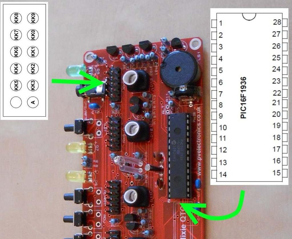
37 6. FIRST CLOCK TEST It is now time to check the basic clock functions and that all tubes are working correctly. 6.1 Insert IC2 and IC3 Insert IC2 and IC3 into their sockets, with the notches aligned as shown below: 6.2 Microcontroller Code Configuration The Microcontroller IC2 needs to be setup for your tube type as the tube connections differ for the 3 types of pinout that the kit supports. However, most tubes use configuration 'A'. If you are using a tube which requires configuration 'A', you can omit this step as the microcontroller is programmed to this configuration as a factory default. However it is still worth noting the procedure below, in case for some reason you accidentally change the configuration you can then change it back. To change the configuration, be sure the supercapacitor is discharged. If it is not discharged, leave the clock unplugged for 6 hours to fully discharge it. Then keep one of the following buttons pressed whilst reconnecting power. This will reconfigure the controller and the change will be stored to non- volatile memory. Configuration A: Press the SET button Configuration B: Press the ADJ button Configuration C: Press the ALARM button After configuring the controller as above you can immediately power off the clock, and proceed to the first tube tests below
38 6.3 First Tube Test Insert the 6 tube cells into the main PCB, ensuring the tubes face forwards (The switches are at the back). Connect a 12V DC power supply (2.1mm central pin type, centre positive) and power up. The clock should start counting 0-9 repeatedly on all tubes. If this does not happen, power off and check all tubes are connected correctly. If the counting order is wrong, go back and repeat step 6.2. Pressing SET will exit the tube test mode with a bleep and the clock will start time display. Do not be tempted to press buttons without knowing the function. If the clock bleeps, shows the time and is incrementing time, this is sufficient at this stage. Power off and disconnect the power supply
 R31 R48 (270 Ω) Start by installing the 18 resistors R31 to R48 and then the 3 transistors Q2, Q3 and Q4.")
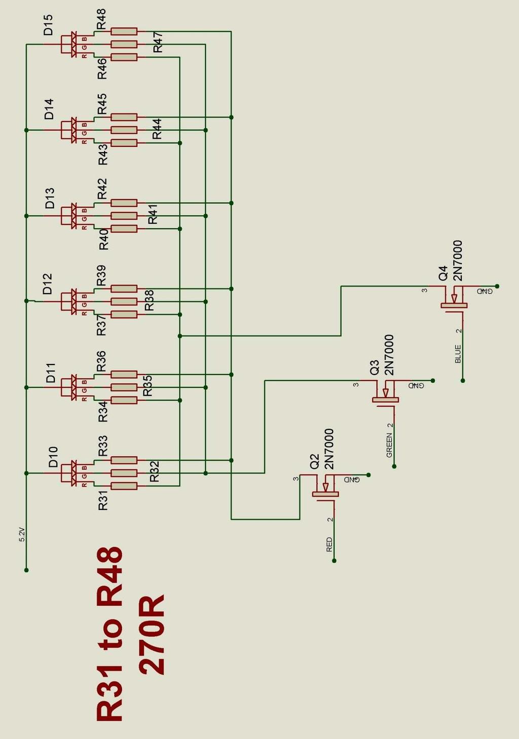
39 7. MOUNTING THE RGB TUBE LIGHTING COMPONENTS 7.1 RGB LEDs D10 D15. Q2 Q4 (2N7000) R31 R48 (270 Ω) Start by installing the 18 resistors R31 to R48 and then the 3 transistors Q2, Q3 and Q4. To install the RGB LEDs, first note the longest of the 4 leads and ensure it goes into the pad marked with the two small circles:

40 Then, place a Nixie Tube assembly into position on the 6X2 connectors. Push the RGB LED gently into position under the tube and then solder in place:
41 8. HOW TO OPERATE THE CLOCK The four buttons have the following functions: SET: Exit tube test routine on cold power-up; Show date; Set time and date; Enter configuration menu; ADJ: Call DCF / MSF; Adjust: time, date, alarm time, configuration parameters; ALARM: Set alarm time; snooze; cancel snooze/alarm; DST: Toggle between DST and Standard Time (+/- 1 Hour) Enter colour setup menu; scroll through colour / time options Entering configuration mode: The principal settings of the clock are stored in flash memory your preferred configuration is stored even after powering off the clock for extended periods. To access the configuration mode press and hold the SET button. After 2 seconds the seconds will become highlighted. Continue holding the button a further 2 seconds until the clock displays in this format: 00-XX-99. The 99 in the seconds digits tells you that you are in the configuration menu. In configuration mode the hours digits diplay the current parameter being adjusted, and the minutes digits display the current value stored against the parameter. For each parameter, and referring to the table below, scroll through the range of possible values by pressing the ADJ button. When the desired value has been reached, move on to the next parameter by pressing the SET button. When the last parameter has been set, pressing SET one more time will revert the clock back to time display mode. The first parameter (0) cannot be changed as it is the software revision number. It will show for several seconds and then move to parameter 1. In all correspondence on support issues, please quote the board type, revision date and software version
42 Parameter Description Values 0 Software revision 10 = version 1.0, 11 = version 1.1 etc 1 12 / 24 Hr mode 0 12 Hr (default) 1 24 Hr 2 Date format 0 = MM.DD.YY (default) 1 = DD.MM.YY 2 = YY.MM.DD (from V1.1 onwards) 3 Leading zero blanking eg. 01:54:32 0 leading zero blanked (default) 1 leading zero displayed 4 Night Mode start hour Night Mode end hour Night Mode 0 Tubes off 1 Dimmed display (default) 7 Master Blank start hour Master Blank end hour Master Blank days 1 0 Off (default) 1 Weekdays 2 - Weekends 3 All days 10 Colon neons mode 0 AM/PM Indication, flashing 1 AM/PM Indication, illuminated 2 Both flash (default) 3 Both illuminated 4 Both off 11 Colon neons during night dimmed mode 2 0 AM/PM Indication, flashing 1 AM/PM Indication, illuminated 2 Both flash 3 Both illuminated (default) 4 Both off 12 Radio time signal source 0 No Radio Time source (default) 3 1 DCF 2 not used 3 MSF 4 - GPS 13 GPS Baud rate Kbps (default) Kbps Kbps Kbps 14 Radio time offset hours 0-13 (default 0) 4 15 Radio time offset mins 0-45 (default 0) 4 16 Radio time offset polarity 0 - Minus time (default) 1 Plus time 17 Reserved leave as Snooze period 0 6 minutes (default) 1 9 minutes 2 12 minutes 3 15 minutes 19 Reserved leave as Time Calibration Factor 0-99 (each unit adjusts by 0.2s per day) 21 Time Calibration Polarity 0 - Make clock slower 1 - Make clock faster
43 Notes: 22 Slots Mode 5 0 Slots disabled 1 Slots every minute 2 - Slots every 10 minutes (default) 3 - Slots every hour 4 Slots at midnight 23 RFT Sync Mode 6 0 DCF / MSF Sync once per day only as per parameter 24 (default) 1 DCF / MSF Sync every hour 24 RFT Daily Sync Hour 0 23 (default 2) 25 RFT Seek Blanking 0 Keep tubes lit for DCF / MSF seek 1 Blank tubes for DCF / MSF seek (default) 26 Display Mode 0 standard change of digits 1 fading digits 2 fading digits with scrollback effect (default) 27 Auto date display each minute 0 Off 1 - Static display of date 2 Scrolling display of date (default) (default 0 gives 15 seconds override) 8 28 Night Mode Override minutes 29 Restore default settings 0 Keep user settings 1 Restore original default settings 9 1. Master Blanking Mode has priority over Night Mode. Use to disable the clock on weekends (eg clock is in office), or during office hours (eg clock is at home). Complete HV shutdown to save power and tube life. 2. Night time neons mode is active when night mode is set to dim. During night time blanking the tubes AND neons are disabled. 3. Clock is fully functional without DCF / MSF / GPS synchronisation. Set time manually. 4. Enter your time zone offset from the synchronisation source. Note that GPS transmits UTC. 5. Visual effect / cathode poisoning prevention all digits on all tubes are cycled for 10 seconds. This setting overrides night blanking or dimming for the duration of the effect (10 seconds). 6. DCF / MSF synchronisation takes place on the hour. If no valid frame is received in 6 minutes, the clock reverts to normal operation. 7. Date will be displayed each minute between 50 and 55 seconds past the minute. 8. Press SET briefly during Night Mode to show time for prescribed period. 9. Set this parameter to 1 to restore original default settings. Internal operations will then load all the original settings and restore the value to
44 Setting the Time and Date: Before setting the time, press 'DST' briefly to toggle between DST and standard time modes. Set according to whether you are currently in DST time or not. From time display mode, press and hold SET button for 2 seconds until the seconds digits are highlighted. Press the ADJ button to reset seconds to zero. Briefly Press SET again and the minutes will be highlighted Press the ADJ button to set the minutes. Briefly Press SET again and the hours will be highlighted. Press the ADJ button to set the hours. Proceed in this fashion to set the calendar: Year, Month and Day. Finally, briefly Press SET again to revert to normal clock operation. Showing Date: From time display mode, briefly press SET button. Date will be shown for 5 seconds, then revert to time display. Auto Date Display: Setting parameter (27) to 1 or 2 will enable auto display of date between 50 and 55 seconds past each minute. Night Blanking Override: During programmed night blanking, the blanking may be overridden to see the time by briefly pressing the SET button. Tubes will remain lit for the period defined in parameter (28). Manual RFT Call: In DCF / MSF modes, pressing ADJ briefly during time display will initiate a manual time seek for maximum 6 minutes, or until a valid time frame is received. Setting Alarm: Press the ALARM Button. The seconds digits show the on / off status of the alarm: 00 (off) or 01 (on). Set on / off status, then minutes followed by hours by using the ALARM and ADJ buttons. When set, the alarm LED will also light
45 Cancelling Alarm: Press ALARM briefly to cancel alarm and enter snooze mode, or a longer press until the clock bleeps, to cancel snooze. Alarm remains set for the next day. Rapid DST Adjustment Press DST briefly to toggle between DST and standard time. The indicator shows whether DST mode is active or not. If time has been synchronised from DCF or MSF sources, this light will be set or cleared automatically. It can still be manually overridden, however the system will re-set the DST status again at the next valid time sync. Note, that GPS time data does not contain DST information, so the DST status will need to be set manually in GPS sync mode as well as manual time-set mode. Calibration of Timekeeping Accuracy Over time you may observe the clock runs faster or slower than an accurate time standard. You can finely adjust the timekeeping by setting configuration parameters 20 and 21. We recommend to precisely set the clock against a known accurate clock, and then record the time drift in seconds after 5 full days (120 hours). Program this value into parameter 20. Set parameter 21 to 0 to slow down the clock and to 1 to speed up the clock

46 9. CONFIGURING THE RGB LED TUBE LIGHTS The clock features a separate and dedicated setup menu for the RGB LED lights, accessed from the DST button. All settings are stored to non-volatile memory, so your favourite colours will still be there after even a long power off. You can set fixed colours and intensities, or program an auto colour cycling effect at your choice of speed. 9.1 Entering RGB LED menu Press and hold the DST button until the display shows: 00: 0:00. NX3 will not be lit. For each hour (0-23), you can set a custom colour Each custom colour can have your choice of RED, GREEN and BLUE values from 0 (colour off) to 8 (maximum brightness) Mix the colours using the SET, ADJ, ALARM buttons. Use low values (1,2 and 3) for low brightness, eg. For night time Set the value to 0 for that colour to be off Once you are happy with the colour for that hour, press DST to move to the next hour Have fun playing with your favourite colours and intensities!
 In the example below, between 19 and 20 hours, the LEDs will be blue with a hint of green ( 0 red, 2 green and 8 blue) -")
47 Colours are displayed live during RGB menu: In the example above, between 11 and 12 hours, the LEDs will be purple (8 red, 0 green and 8 blue) In the example below, between 19 and 20 hours, the LEDs will be blue with a hint of green ( 0 red, 2 green and 8 blue)

48 9.2 Setting auto colour cycling Setting colour RED to value 9 has a special meaning: This will enable auto colour cycling for the specified hour. The speed of the cycling will then be governed by the GREEN value: 0 = very slow change 9 = very fast change This auto colour cycling mode is explained in the picture below: Red = 9, therefore Auto Colour Cycling is enabled for hours Green = 3, so speed is 3. Blue value has no effect. Note: The colours do not cycle live during Auto Colour Cycling setup. The cycling starts only during normal time and date display
49 10. USING A RADIO FREQUENCY TIME RECEIVER OR GPS RECEIVER The clock can automatically synchronise time from DCF (Europe), and MSF (UK) long wave time transmitters. The clock can also receive time from a GPS receiver that transmits information using NMEA-0183 protocol, using the $GPRMC sentence Configuring for RFT or GPS Synchronisation. Set parameter 12: 1: DCF 2: unused 3: MSF 4: GPS If using GPS, set the baud rate in parameter (13) Set parameters 14 and 15 for the hours and minutes your time zone is offset from the synchronisation source. This is usually only whole hours. Examples: o UK is 1 hour offset from the time transmitted by the DCF transmitter o France has no offset from the time transmitted by the DCF transmitter Set parameter (16) to identify whether the offset is minus (0) or positive (1) of the time source. Set parameter (23) to select between hourly seek and daily seek in DCF / MSF modes. If you have selected daily seek, use parameter (24) to set the time of the daily seek in DCF / MSF modes. If you intend to place the RFT receiver module closer to the clock PCB than 6 ft / 2 metres, the clock will need to disable HV and switch off the tubes for time seek, otherwise the switchmode power supply will prevent reception. Select blanking during time seek by setting parameter (25) to

50 10.2 Connecting a Radio Time receiver The clock has been designed for, and tested with our Radio Frequency Time (RFT) Receiver Modules. (available separately from PV Electronics). DCF Module: For receiving time signals from transmitter at Frankfurt, Germany. Reception is possible within a 2000Km radius of Frankfurt. MSF Module: For receiving time signals from the transmitter at Anthorn, UK. Reception is possible within the UK, Eire, Northern France, and Norway. Please note: 1. The long wave signals propagate further at night, so the clock is configured by default to synchronize at 2am. 2. Suitable Power Supplies: If using a switching power supply, it must have an earth connection. Cheap Chinese switching adapters cause too much interference and will not work. Alternatively use an old-fashioned transformer type AC to DC adapter. 3. The time signals are intended that a receiving clock may collect time data intermittently. The signal strength and fidelity is not like a 'TV Signal', where one can get a perfect signal any time at will
51 10.3 Setting Up for First Reception. 1. Ensure the correct setting has been applied to Config 12: 1 = DCF 3 = MSF 2. For the first tests, ensure Config 25 is set to value 1, to make the HV converter switch off for synchronisation. This stops any noise created by the HV converter. 3. Set Config for your location's time zone offset from the transmitter. 4. Connect the receiver, and place horizontally by a window, broadside on to the transmitter as far as is possible. 5. Wait until after dark, and preferable the early hours. 6. Command a manual seek, by pressing the middle 'Adj' button. The tubes should switch off. The LED on the receiver module will now not be affected by the HV converter, and after seconds start to flash regularly, showing the one pulse per second data from the transmitter. If your Module's red LED does not start to flash regularly, go back and check 1-6. of this section. If the red LED does not flash regularly, you will not get synchronisation! 7. At the start of the minute, the clock should start collecting data, and if so it will start flashing the green LED rapidly. Look for any LED activity at the start of the minute, using a known time source as the reference. 8. After 60 seconds of gathering data, the clock will illuminate the green LED, set the time and switch the tubes back on. 9. Once the system has been seen to work correctly, you can experiment with the antenna in different locations, and it may be possible to have the tubes stay on for time synchonisation. 10. Many other electrical applicances such as TVs and mobile phones reception when in close proximity. Metal objects cause reception problems too Place and design your case so the antenna is as far away from the PCB as possible


52 10.4 Connecting a GPS receiver The clock has been designed for, and tested with our Micro GPS Receiver (available separately from PV Electronics)
53 10.5 Function of the GPS / RFT indicator LED (D7): No Radio Synchronisation source installed (parameter (12) = 0) LED is permanently off RFT or GPS Synchronisation enabled (parameter (12) = 1-4) The LED will be ON if the clock has synchronised in the last two hours; slowly flashing if the last synchronisation was between 2 hours and 24 hours ago; and off if the last synchronisation is older than 24 hours. If DCF or MSF mode is selected, the indicator will flash rapidly whilst the clock is actually receiving and processing a valid time frame. Additionally, the indicator will flash very briefly each second whilst seeking a RFT frame. Radio Time Source The function of the RFT indicator LED may be summarised in the table below: Sync < 2 Hrs Sync >2 Hrs Sync < 24 Hrs Sync > 24 Hrs Seeking RFT Frame Aquiring RFT Frame None Off Off Off - - DCF / MSF On Slow Flash Off Intermittent Fast Flash Flash GPS On Slow Flash Off
54 11. CONNECTIVITY DIAGRAM FOR TROUBLESHOOTING Please refer to the diagram on the next page. If you have problems with missing digits from the display or no digits displaying at all (even though High voltage is present and the clock makes bleeps when pressing the 'SET' Button) then you should check all connections to the HV5812 IC using the chart below. Set your meter to continuity setting. This is the setting where it bleeps when you touch the two probes together Data connections from IC2 to IC3 IC3 (HV5812) IC2 (PIC 16F1936) Function Pin Number Pin Number 27 3 Data 15 4 Clock 16 5 Strobe 11.2 Cathode connections from IC3 to tube pin headers IC3 (HV5812) Pin Number NX1, NX2, NX3 Cathode IC3 (HV5812) Pin Number 17 K5 3 KK9 18 K4 4 KK8 19 K6 5 KK7 20 K7 6 KK6 21 K3 7 KK4 22 K2 8 KK5 23 K1 9 KK0 24 K0 10 KK1 25 K9 11 KK2 26 K8 12 KK3 NX4, NX5, NX6 Cathode
55 - 55 -

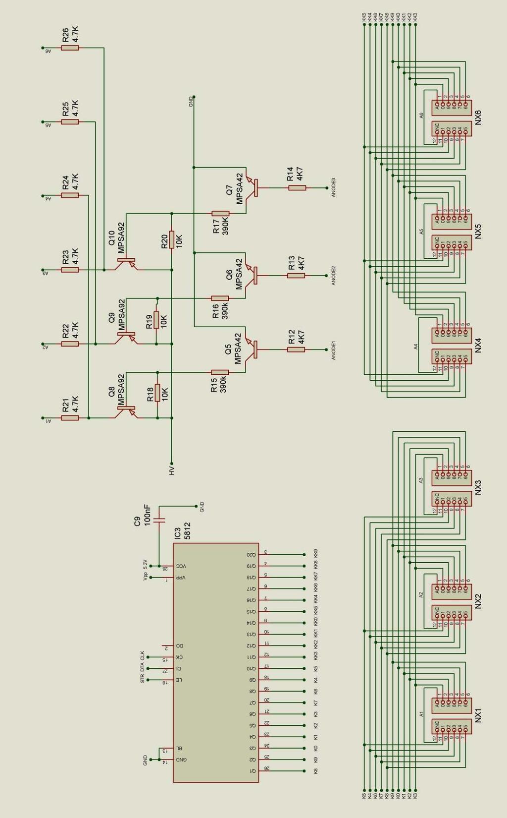
56 12. CIRCUIT DIAGRAM
57 - 57 -
58 - 58 -
Nixie Clock Type Nixie Maestro
 Assembly Instructions and User Guide Nixie Clock Type Nixie Maestro - 1 - Issue Number Date REVISION HISTORY Reason for Issue 4 01 April 2017 New version with neons for AM / PM 3 10 December 2014 Typing
Nixie Clock Type Quattro'
 Assembly Instructions And User Guide Nixie Clock Type Quattro' - 1 - Issue Number Date REVISION HISTORY 2 8 Sept 2012 Errors corrected 1 27 July 2012 New document Reason for Issue - 2 - 1.1 Nixie Quattro
Nixie Clock Type Frank 3'
 Assembly Instructions And User Guide Nixie Clock Type Frank 3' - 1 - REVISION HISTORY Issue Number Date Reason for Issue 4 16 December 2016 New diode for D2 3 12 November 2012 Improved first clock test
Nixie Clock Type IN-8 & NL840 Nixie'
 Assembly Instructions And User Guide Nixie Clock Type IN-8 & NL840 Nixie' - 1 - REVISION HISTORY Issue Number Date 4 15 December 2016 New diode for D2 3 30 August 2014 Typos 2 25 June 2014 Added NL840
Nixie Clock Type SixNix
 Assembly Instructions And User Guide Nixie Clock Type SixNix - 1 - Issue Number Date REVISION HISTORY Reason for Issue 6 20 March 2014 Removed WWVB Support 5 14 July 2012 New Board Issue - 19 July 12 4
Assembly Instructions And User Guide. Nixie FunKlock. FunKlock Issue 4 (1 February 2017)
") Assembly Instructions And User Guide Nixie FunKlock - 1 - Issue Number Date REVISION HISTORY 4 1 February 2017 New diode for D2 3 27 December 2013 C7 / C8 error page 15 2 7 November 2013 Errors corrected
Assembly Instructions And User Guide Nixie FunKlock - 1 - Issue Number Date REVISION HISTORY 4 1 February 2017 New diode for D2 3 27 December 2013 C7 / C8 error page 15 2 7 November 2013 Errors corrected
Nixie Clock Type Nixie QTC Plus
 Assembly Instructions And User Guide Nixie Clock Type Nixie QTC Plus - 1 - REVISION HISTORY Issue Date Number Draft 1 29 August 2018 New document Reason for Issue - 2 - 1. INTRODUCTION 1.1 Nixie QTC Plus
SN-Class Nixie Clock Kits
 Assembly Instructions And User Guide SN-Class Nixie Clock Kits - 1 - REVISION HISTORY Issue Date Reason for Issue Number 1 20 November 2017 New document - 2 - 1. INTRODUCTION 1.1 About the How can the
Nixie Clock Type Frank 2 Z570M
 Assembly Instructions And User Guide Nixie Clock Type Frank 2 Z570M Software version: 7R PCB Revision: 11 April 09-1 - 1. INTRODUCTION 1.1 About the clock Nixie clock type Frank 2 is a compact design with
Nixie Clock Type Frank 3
 Assembly Instructions And User Guide Nixie Clock Type Frank 3 Software version: 7R PCB Version: 11 April 09-1 - 1. INTRODUCTION 1.1 About the clock Nixie clock type Frank 3 is a compact design with all
Assembly Instructions And User Guide. Elite Nixie. Nixie Tube Clock Elite Issue 2 (07 June 2018)
") Assembly Instructions And User Guide Elite Nixie - 1 - REVISION HISTORY Issue Number Date Reason for Issue 2 07 June 2018 Added more NL840 details 1 04 May 2018 New document - 2 - 1. INTRODUCTION Here
Assembly Instructions And User Guide Elite Nixie - 1 - REVISION HISTORY Issue Number Date Reason for Issue 2 07 June 2018 Added more NL840 details 1 04 May 2018 New document - 2 - 1. INTRODUCTION Here
Nixie Tube Clock Type Marsden
 Assembly Instructions And User Guide Nixie Tube Clock Type Marsden Software version: RTC-1.3 PCB Revision: 16 Aug 10-1 - 1. INTRODUCTION 1.1 About the clock Nixie clock type Marsden is a compact design
Nixie Clock Kit V1.08 Assembly and Operation
 Nixie Clock Kit V1.08 Assembly and Operation Hardware Revision 14.05.2005 Software Version 6.0 Revision 19.04.2006 This document is copyrighted. No parts of this documentation may be used commercially.
Documentation VFD clock 8 a clock
 Documentation VFD clock 8 a clock This documentation is protected by our copyright. It must not be used for commercial purposes. Congratulations on your purchase of your VFD clock. To guarantee success
Arduino Nixie Clock Classic Rev4 and Rev5 All In One Modular Rev2
 Arduino Nixie Clock Classic Rev4 and Rev5 All In One Modular Rev2 Operating Instructions Firmware V47 Supported Models: Classic Rev4 Classic Rev5 Modular Rev2 All-In-One NixieClockUserManualV47 About this
Arduino Nixie Clock Modular Rev3
 Arduino Nixie Clock Modular Rev3 Operating Instructions Firmware V348 Supported Models: Modular Revision 3 NixieClockUserManualV348 About this document This is the user instruction manual for the Nixie
Arduino Nixie Clock Classic Rev4 and Rev5 All In One
 Arduino Nixie Clock Classic Rev4 and Rev5 All In One Operating Instructions Firmware V52 Supported Models: Classic Rev4 Classic Rev5 All-In-One NixieClockUserManualV52 About this document This is the user
Introduction 1. Green status LED, controlled by output signal ST. Sounder, controlled by output signal Q6. Push switch on input D6
 Introduction 1 Welcome to the GENIE microcontroller system! The activity kit allows you to experiment with a wide variety of inputs and outputs... so why not try reading sensors, controlling lights or
7 SEGMENT LED DISPLAY KIT
 ESSENTIAL INFORMATION BUILD INSTRUCTIONS CHECKING YOUR PCB & FAULT-FINDING MECHANICAL DETAILS HOW THE KIT WORKS CREATE YOUR OWN SCORE BOARD WITH THIS 7 SEGMENT LED DISPLAY KIT Version 2.0 Which pages of
Nixie Clock Kit IN-12B color LED backlit Operation Manual Nixie Clock Kit IN-12B V6.0 ( All Right Reserved 2015 )
") Nixie Clock Kit IN-B color LED backlit Operation Manual Nixie Clock Kit IN-B V. ( All Right Reserved ) - - Operation Manual IN-B Nixie Clock Power for your Nixie Clock The clock does not include a wall
Nixie Clock Kit IN-B color LED backlit Operation Manual Nixie Clock Kit IN-B V. ( All Right Reserved ) - - Operation Manual IN-B Nixie Clock Power for your Nixie Clock The clock does not include a wall
N3ZI Digital Dial Manual For kit with Backlit LCD Rev 4.00 Jan 2013 PCB
 N3ZI Digital Dial Manual For kit with Backlit LCD Rev 4.00 Jan 2013 PCB Kit Components Item Qty Designator Part Color/Marking PCB 1 LCD Display 1 LCD 1602 Volt Regulator 1 U1 78L05, Black TO-92 Prescaler
DDS VFO CONSTRUCTION MANUAL. DDS VFO Construction Manual Issue 1.1 Page 1
 DDS VFO CONSTRUCTION MANUAL DDS VFO Construction Manual Issue 1.1 Page 1 Important Please read before starting assembly STATIC PRECAUTION The DDS VFO kit contains the following components which can be
Arduino Nixie Clock Modular Rev3
 Arduino Nixie Clock Modular Rev3 Operating Instructions Firmware V352 Supported Models: Modular Revision 3 NixieClockUserManualV352 About this document This is the user instruction manual for the Nixie
8 PIN PIC PROGRAMMABLE BOARD (DEVELOPMENT BOARD & PROJECT BOARD)
") ESSENTIAL INFORMATION BUILD INSTRUCTIONS CHECKING YOUR PCB & FAULT-FINDING MECHANICAL DETAILS HOW THE KIT WORKS LEARN ABOUT PROGRAMMING WITH THIS 8 PIN PIC PROGRAMMABLE BOARD (DEVELOPMENT BOARD & PROJECT
ESSENTIAL INFORMATION BUILD INSTRUCTIONS CHECKING YOUR PCB & FAULT-FINDING MECHANICAL DETAILS HOW THE KIT WORKS LEARN ABOUT PROGRAMMING WITH THIS 8 PIN PIC PROGRAMMABLE BOARD (DEVELOPMENT BOARD & PROJECT
N3ZI Digital Dial Manual For kit with Serial LCD Rev 3.04 Aug 2012
 N3ZI Digital Dial Manual For kit with Serial LCD Rev 3.04 Aug 2012 Kit properly assembled and configured for Standard Serial LCD (LCD Not yet connected) Kit Components Item Qty Designator Part Color/Marking
MONO AMPLIFIER KIT ESSENTIAL INFORMATION. Version 2.2 CREATE YOUR OWN SPEAKER DOCK WITH THIS
 ESSENTIAL INFORMATION BUILD INSTRUCTIONS CHECKING YOUR PCB & FAULT-FINDING MECHANICAL DETAILS HOW THE KIT WORKS CREATE YOUR OWN SPEAKER DOCK WITH THIS MONO AMPLIFIER KIT Version 2.2 Build Instructions
Christmas LED Snowflake Project
 Christmas LED Snowflake Project Version 1.1 (01/12/2008) The snowflake is a follow-on from my Christmas star project from a few years ago. This year I decided to make a display using only white LEDs, shaped
VU-1 VU Meter Kit Volume Unit Meter
 VU-1 VU Meter Kit Volume Unit Meter Simplicity Counts, Detail Matters. No part of this document may be reproduced, either mechanically or electronically, posted online on the Internet, in whole or in part,
WiFi Time Provider v1 for Arduino Nixie Clock Operating Instructions & Construction Manual
 WiFi Time Provider v1 for Arduino Nixie Clock Operating Instructions & Construction Manual Document V001c Contact Information If you want to get in contact with us, please email to: nixie@protonmail.ch
Arduino IN-14 Nixie Clock v42 All-In-One Clock Operating Instructions & Construction Manual
 Arduino IN-14 Nixie Clock v42 All-In-One Clock Operating Instructions & Construction Manual NixieClockIN14InstructionManualRev2V42 Contact Information If you want to get in contact with us, please email
Total solder points: 123 Difficulty level: beginner 1. advanced AUDIO ANALYZER K8098. audio gea Give your. . high-tech ILLUSTRATED ASSEMBLY MANUAL
 Total solder points: 123 Difficulty level: beginner 1 2 3 4 5 advanced AUDIO ANALYZER K8098 ra audio gea Give your. look high-tech ILLUSTRATED ASSEMBLY MANUAL H8098IP-1 Features & Specifications Features
ELECTRONIC GAME KIT TEACHING RESOURCES. Version 2.0 BUILD YOUR OWN MEMORY & REACTIONS
 TEACHING RESOURCES SCHEMES OF WORK DEVELOPING A SPECIFICATION COMPONENT FACTSHEETS HOW TO SOLDER GUIDE BUILD YOUR OWN MEMORY & REACTIONS ELECTRONIC GAME KIT Version 2.0 Index of Sheets TEACHING RESOURCES
GUIDE TO ASSEMBLY OF ERICA SYNTHS DELAY MODULE
 If you are reading this, most probably, you are about to build Erica Synths DIY DELAY module. The module is 4mm deep, skiff friendly, has solid mechanical construction and doesn t require wiring. Erica
Mal-2 assembly guide v1.0
 Mal-2 assembly guide v.0 SONIC POTIONS Schematic and BOM The BOM can be found on Google Docs Prepare the PCB Separate the PCBs using some pliers. PCB We start with the lower PCB and assemble it beginning
Arduino Modular IN-14 Nixie Clock Rev2 V45 All-In-One Modular Clock Operating Instructions & Construction Manual
 Arduino Modular IN-14 Nixie Clock Rev2 V45 All-In-One Modular Clock Operating Instructions & Construction Manual NixieClockModularInstructionManualRev2V45 Contact Information If you want to get in contact
POINTS POSITION INDICATOR PPI4
 POINTS POSITION INDICATOR PPI4 Monitors the brief positive operating voltage across points motors when they are switched Lights a corresponding led on a control panel to show the last operation of each
MAKE AN RGB CONTROL KNOB.
 MAKE AN RGB CONTROL KNOB. This is a knob based colour changing controller that uses a custom programmed microcontroller to pack a lot of features into a small affordable kit. The module can drive up to
COLOUR CHANGING USB LAMP KIT
 TEACHING RESOURCES SCHEMES OF WORK DEVELOPING A SPECIFICATION COMPONENT FACTSHEETS HOW TO SOLDER GUIDE SEE AMAZING LIGHTING EFFECTS WITH THIS COLOUR CHANGING USB LAMP KIT Version 2.1 Index of Sheets TEACHING
Tube Cricket Build Guide
 Tube Cricket Build Guide The Tube Cricket is a small-wattage amp that puts out about 1 watt of audio power. With a 12AU7 tube-preamp and a JRC386 power amp, the Tube Cricket gives you great tone in a compact
16 Stage Bi-Directional LED Sequencer
 16 Stage Bi-Directional LED Sequencer The bi-directional sequencer uses a 4 bit binary up/down counter (CD4516) and two "1 of 8 line decoders" (74HC138 or 74HCT138) to generate the popular "Night Rider"
VU Meter Buffer DIY Kit
 VU Meter Buffer DIY Kit Warning This document is distributed for educational purposes only. This equipment operates at potentially lethal voltages. Only trained, qualified personnel should operate, maintain,
DIY Guide - Building Franky v1.1, the SEGA Audio and Videocard for MSX
 DIY Guide - Building Franky v1.1, the SEGA Audio and Videocard for MSX 2015 FRS & MSXpró. Translation by FRS and Supersoniqs. Table of Contents Introduction... 3 Materials needed... 3 Audio volume boost...
MAIN PCB (The small one) OPEN MAIN BOARD BAG A
 OPEN MAIN BOARD BAG A") THANKS FOR CHOOSING ONE OF OUR KITS! This manual has been written taking into account the common issues that we often find people experience in our workshops. The order in which the components are placed
THANKS FOR CHOOSING ONE OF OUR KITS! This manual has been written taking into account the common issues that we often find people experience in our workshops. The order in which the components are placed
QUIZ BUZZER KIT TEACHING RESOURCES. Version 2.0 WHO ANSWERED FIRST? FIND OUT WITH THIS
 TEACHING RESOURCES SCHEMES OF WORK DEVELOPING A SPECIFICATION COMPONENT FACTSHEETS HOW TO SOLDER GUIDE WHO ANSWERED FIRST? FIND OUT WITH THIS QUIZ BUZZER KIT Version 2.0 Index of Sheets TEACHING RESOURCES
DIY KIT MHZ 8-DIGIT FREQUENCY METER
 This kit is a stand-alone frequency meter capable of measuring repetitive signals up to a frequency of 50MHz. It has two frequency ranges (15 and 50 MHz) as well as two sampling rates (0.1 and 1 second).
Introduction 1. Digital inputs D6 and D7. Battery connects here (red wire to +V, black wire to 0V )
") Introduction 1 Welcome to the magical world of GENIE! The project board is ideal when you want to add intelligence to other design or electronics projects. Simply wire up your inputs and outputs and away
Introduction 1 Welcome to the magical world of GENIE! The project board is ideal when you want to add intelligence to other design or electronics projects. Simply wire up your inputs and outputs and away
Lab 7: Soldering - Traffic Light Controller ReadMeFirst
 Lab 7: Soldering - Traffic Light Controller ReadMeFirst Lab Summary The two-way traffic light controller provides you with a quick project to learn basic soldering skills. Grading for the project has been
Multi-Key v2.4 Multi-Function Amplifier Keying Interface
 Multi-Key v2.4 Multi-Function Amplifier Keying Interface ASSEMBLY & OPERATION INSTRUCTIONS INTRODUCTION The Harbach Electronics, LLC Multi-Key is a multi-function external device designed for the safe
Digital Clock. Perry Andrews. A Project By. Based on the PIC16F84A Micro controller. Revision C
 Digital Clock A Project By Perry Andrews Based on the PIC16F84A Micro controller. Revision C 23 rd January 2011 Contents Contents... 2 Introduction... 2 Design and Development... 3 Construction... 7 Conclusion...
SceneStyle2 User Guide
 SceneStyle2 User Guide Mode Lighting (UK) Limited. The Maltings, 63 High Street, Ware, Hertfordshire, SG12 9AD, UNITED KINGDOM. Telephone: +44 (0) 1920 462121 Facsimile: +44 (0) 1920 466881 e-mail: website:
ADD AN AUDIO MESSAGE TO YOUR PRODUCT WITH THIS RECORD & PLAYBACK KIT
 ADD AN AUDIO MESSAGE TO YOUR PRODUCT WITH THIS RECORD & PLAYBACK KIT BUILD INSTRUCTIONS Before you start take a look at the Printed Circuit Board (PCB). The components go in the side with the writing on
RECORD & PLAYBACK KIT
 TEACHING RESOURCES SCHEMES OF WORK DEVELOPING A SPECIFICATION COMPONENT FACTSHEETS HOW TO SOLDER GUIDE ADD AN AUDIO MESSAGE TO YOUR PRODUCT WITH THIS RECORD & PLAYBACK KIT Version 2.1 Index of Sheets TEACHING
Introduction 1. Green status LED, controlled by output signal ST
 Introduction 1 Welcome to the magical world of GENIE! The project board is ideal when you want to add intelligence to other design or electronics projects. Simply wire up your inputs and outputs and away
Total solder points: 117 Difficulty level: beginner advanced. RGB Controller K8088 ILLUSTRATED ASSEMBLY MANUAL
 Total solder points: 117 Difficulty level: beginner 1 2 3 4 5 advanced RGB Controller K8088 Control incandescent bulbs, LEDs, common anode led strips, etc... ILLUSTRATED ASSEMBLY MANUAL H8088IP-1 Features
TKEY-K16. Touch CW automatic electronic keyer. (No moving parts no contacts) Assembly manual. Last review: March 15, 2018
 Assembly manual. Last review: March 15, 2018") TKEY-K16 Touch CW automatic electronic keyer (No moving parts no contacts) Assembly manual Last review: March 15, 2018 Commands and use manual of the K16 and Updates and news: www.ea3gcy.com Thanks for
TKEY-K16 Touch CW automatic electronic keyer (No moving parts no contacts) Assembly manual Last review: March 15, 2018 Commands and use manual of the K16 and Updates and news: www.ea3gcy.com Thanks for
Scoreboard Operator s Instructions MPCX SCD / DGT / Pitch Time Control
 Scoreboard Operator s Instructions MPCX SCD / DGT / Pitch Time Control Since 1934 Retain this manual in your permanent files Rev. 2/3/2012 135-0136 These Instructions are for the Following Models: LED
Ten-Tec (865) Service Department:(865)
 Service Department:(865)") Ten-Tec (865) 453-7172 Service Department:(865) 428-0364 Installation Instructions for Ten-Tec Jupiter AT538K Tuner Kit The installation of the AT538K is divided into two steps. The first step is to reprogram
Ten-Tec (865) 453-7172 Service Department:(865) 428-0364 Installation Instructions for Ten-Tec Jupiter AT538K Tuner Kit The installation of the AT538K is divided into two steps. The first step is to reprogram
Aspect 2 Circuit Digital Scene Control
 Aspect 2 Circuit Digital Scene Control S p e c i f i c a t i o n 2 circuits of trailing edge dimming 500W total between the two circuits Both circuits feature independent overload, short-circuit and open-circuit
Build A Video Switcher
 Build A Video Switcher VIDEOSISTEMAS serviciotecnico@videosistemas.com www.videosistemas.com Reprinted with permission from Electronics Now Magazine September 1997 issue Copyright Gernsback Publications,
STX Stairs lighting controller.
 Stairs lighting controller STX-1795 The STX-1795 controller serves for a dynamic control of the lighting of stairs. The lighting is switched on for consecutive steps, upwards or downwards, depending on
DL-1A. RF dummy load - 50Ω 20W. Assembly manual. Last update: May 1, Thank you for constructing the DL-1A dummy load kit
 DL-1A RF dummy load - 50Ω 20W Assembly manual Last update: May 1, 2016 ea3gcy@gmail.com Updates and news at: www.qsl.net/ea3gcy Thank you for constructing the DL-1A dummy load kit Have fun assembling it
Revision 1.2d
 Specifications subject to change without notice 0 of 16 Universal Encoder Checker Universal Encoder Checker...1 Description...2 Components...2 Encoder Checker and Adapter Connections...2 Warning: High
Bill of Materials: Super Simple Water Level Control PART NO
 Super Simple Water Level Control PART NO. 2169109 Design a simple water controller in which electrodes are required to sense high and low water levels in a tank. Whenever the water level falls below the
FSM User Guide Page 1 of 28
 FSM User Guide Page 1 of 28 Field Strength Meter User Guide and Kit Assembly Instructions PCB V1.1 Important: Always use or print this document in colour as there are references to the colours of components.
Operating Manual. Basic Control BC16. two-channel for eco moon
 Operating Manual Basic Control BC16 two-channel for eco moon Dear Customer, Thank you for choosing a WALTRON daytime lighting controller. Your daytime lighting controller is a high-quality product that
Timer Modules. MEU11 24 Hour Module, MEU17 7 Day Module (Without Housing)
") Timer Modules MEU11 24 Hour Module, MEU17 7 Day Module (Without Housing) EMU11 24 Hour Module, EMU17 7 Day Module (With Housing Giving panel mounting facility) Installation & Operating Instructions 1 1.
Timer Modules MEU11 24 Hour Module, MEU17 7 Day Module (Without Housing) EMU11 24 Hour Module, EMU17 7 Day Module (With Housing Giving panel mounting facility) Installation & Operating Instructions 1 1.
XTAL Bank DDS Version 0.02 Sept Preliminary, highly likely to contain numerous errors
 XTAL Bank DDS Version 002 Sept 7 2012 Preliminary, highly likely to contain numerous errors The photo above shows the fully assembled Xtal Bank DDS with 2 DDS modules installed (The kit is normally only
FN:4181NX_M1.DOC MC4181NX MASTER CLOCK MC4181NX
 FN:4181NX_M1.DOC MC4181NX MASTER CLOCK MC4181NX TABLE OF CONTENTS 1.0 INTRODUCTION 2.0 SPECIFICATIONS 3.0 INSTALLATION 4.0 GETTING STARTED 4.1 The Auto-Prompt Display 4.2 The Cursor, Entering Data 4.3
LCD Thermometer / Clock S No. 1253
 Installation and Operating Manual LCD Thermometer / Clock S No. 1253 The 3 fold thermometer with crystal clock is purpose build for the mounting in caravans, boats and intervention vehicles. Please read
Analog Style LED Clock
 Analog Style LED Clock Operation and Assembly Manual For use with PCB Rev 2.1 Copyright 2018 All Rights Reserved. Manual version 2.1c, for use with PCB revision 2.1, Software version 2.0.0. The electronic
Lab 7: Soldering - Traffic Light Controller ReadMeFirst
 Lab 7: Soldering - Traffic Light Controller ReadMeFirst Lab Summary The two way traffic light controller provides you with a quick project to learn basic soldering skills. Grading for the project has been
Fixed Audio Output for the K2 Don Wilhelm (W3FPR) & Tom Hammond (NØSS) v August 2009
 & Tom Hammond (NØSS) v August 2009") Fixed Audio Output for the K2 Don Wilhelm (W3FPR) & Tom Hammond (NØSS) v. 2.1 06 August 2009 I have had several requests to provide a fixed audio output from the K2. After looking at the circuits that
Fixed Audio Output for the K2 Don Wilhelm (W3FPR) & Tom Hammond (NØSS) v. 2.1 06 August 2009 I have had several requests to provide a fixed audio output from the K2. After looking at the circuits that
NETWORK COMPASS USER MANUAL CONTENTS
 CONTENTS NETWORK COMPASS USER MANUAL GENERAL INTRODUCTION TO B&G NETWORK...2 INTRODUCTION TO NETWORK COMPASS...3 COMPASS DISPLAY UNIT...4 EXAMPLE SYSTEMS USING NETWORK COMPASS...4 INITIAL POWER-UP...5
ELECTRONIC GAME KIT ESSENTIAL INFORMATION. Version 2.0 BUILD YOUR OWN MEMORY & REACTIONS
 ESSENTIAL INFORMATION BUILD INSTRUCTIONS CHECKING YOUR PCB & FAULT-FINDING MECHANICAL DETAILS HOW THE KIT WORKS BUILD YOUR OWN MEMORY & REACTIONS ELECTRONIC GAME KIT Version 2.0 Build Instructions Before
Installing The PK-AM keyer and. from Jackson Harbor Press Operating: A Morse code keyer chip with pot speed control
 Installing The PK-AM keyer and from Jackson Harbor Press Operating: A Morse code keyer chip with pot speed control The PK-AM keyer is a modification for the PK-AM kit, it changes the AM transmitter to
ULTRA-VANSTAT WIRELESS PROGRAMMABLE THERMOSTAT FOR CARAVANS
 ULTRA-VANSTAT WIRELESS PROGRAMMABLE THERMOSTAT FOR CARAVANS NOT SUPPLIED PROGRAMMER / TRANSMITTER RECEIVER THIS DOMESTIC STYLE WIRELESS 7 DAY PROGRAMMABLE HEATER CONTROL REPLACES THE TRUMA ULTRAHEAT SWITCH
Thank you for purchasing this product. If installing for someone else, please ensure that the instructions are handed to the householder.
 Instruction Manual TPSE201 (181422) - BOSS TM Universal Programmer TPSE101 (569565) - BOSS TM Universal Timeswitch Thank you for purchasing this product. If installing for someone else, please ensure that
FN:4181M5.DOC MC4181N SERIES MASTER CLOCKS MC4181N
 FN:4181M5.DOC MC4181N SERIES MASTER CLOCKS MC4181N TABLE OF CONTENTS 1.0 INTRODUCTION 2.0 SPECIFICATIONS 3.0 INSTALLATION 4.0 GETTING STARTED 4.1 The Auto-Prompt Display 4.2 The Cursor, Entering Data 4.3
Part No. ENC-LAB01 Users Manual Introduction EncoderLAB
 PCA Incremental Encoder Laboratory For Testing and Simulating Incremental Encoder signals Part No. ENC-LAB01 Users Manual The Encoder Laboratory combines into the one housing and updates two separate encoder
Scoreboard Operator s Instructions MPCX Volleyball Control
 Scoreboard Operator s Instructions MPCX Volleyball Control Since 1934 Retain this manual in your permanent files Rev. 2/3/2012 135-0137 These Instructions are for the Following Models: LED models: Incandescent
Safety Information. Camera System. If you back up while looking only at the monitor, you may cause damage or injury. Always back up slowly.
 Table of Contents Introduction...3 Safety Information...4-6 Before Beginning Installation...7 Installation Guide...8 Wiring Camera & Monitor...9-10 Replacement Installation Diagram...11 Clip-On Installation
Analog/digital watch Multi frequency reception, 4 digit LCD, 3 hands. Preliminary Specification
 Analog/digital watch Multi frequency reception, 4 digit LCD, 3 hands Preliminary Specification Supplier: Asia Limited Unit 125, 1/F., Liven House, 61-63 King Yip Street, Kwun Tong, HK SAR Issued on: 20.12.2005
FRQM-2 Frequency Counter & RF Multimeter
 FRQM-2 Frequency Counter & RF Multimeter Usage Instructions Firmware v2.09 Copyright 2007-2011 by ASPiSYS Ltd. Distributed by: ASPiSYS Ltd. P.O.Box 14386, Athens 11510 (http://www.aspisys.com) Tel. (+30)
Timer Modules. EL11 24 Hour Module EL17 7 Day Module. Installation & Operating Instructions
 Timer Modules EL11 24 Hour Module EL17 7 Day Module Installation & Operating Instructions 1 1. General Information These instructions should be read carefully and retained for further reference and maintenance.
RSH27 Nixie Tube Socket with LED
 Contents: 1. Applications of the socket 2. Solder instructions of the socket 3. Drawing of the assembled socket 4. Section drawing of the socket with IN-8 tube 5. Drawing and technical data of the tube
SPX-5600 Series. Operations Manual. Suprex Reader Extender - RF Wireless Interface SPX-5600MAN. Page 1 of 20
 SPX-5600 Series Operations Manual Suprex Reader Extender - RF Wireless Interface SPX-5600MAN Page 1 of 20 SPX-5600 Series: Cypress Suprex SPX-5600 Series This manual covers the operation and setup of the
Inputs and outputs. Connecting leads. Buzzer
 Inputs and outputs Mr Bit experiments are designed to help younger pupils get started with connecting sensors and devices to the BBC micro:bit. They are useful 'warm-up' activities before attempting Mr
Modellbahn Digital Peter Stärz
 Modellbahn Digital Peter Stärz Dresdener Str. 68 D-02977 Hoyerswerda +49 3571 404027 www.firma-staerz.de info@firma-staerz.de 8-fold Track Occupancy Detector for digital systems with two-wire track (e.g.
Troubleshooting CS800/LC900 Bikes
 Troubleshooting CS800/LC900 Bikes CS800/900LC Bike Troubleshooting Entering the Maintenance Mode 15 Touch Screen: The Maintenance Mode is designed to help the tech determine certain faults in the upper
REMOTE DISPLAY WIRELESS DECODER MK II
 REMOTE DISPLAY WIRELESS DECODER MK II INSTALLATION MANUAL Part No. LED-DEC 1. Contents 1. Contents... 1 2. Equipment List... 2 3. Overview... 2 Introduction... 2 Location Selection **Important **... 2
NewScope-7A Operating Manual
 2016 SIMMCONN Labs, LLC All rights reserved NewScope-7A Operating Manual Preliminary May 13, 2017 NewScope-7A Operating Manual 1 Introduction... 3 1.1 Kit compatibility... 3 2 Initial Inspection... 3 3
This Unit may form part of a National Qualification Group Award or may be offered on a free standing basis.
 National Unit Specification: general information CODE F5JJ 11 SUMMARY The Unit is intended for candidates with little or no prior knowledge of Analogue or Digital Electronic Circuits. It provides an opportunity
L, LTC, LTM, LT are registered trademarks of Linear Technology Corporation. Other product
 DESCRIPTION WARNING! Do not look directly at operating LED. This circuit produces light that can damage eyes. Demo Circuit 1265 QUICK START GUIDE LTC3220/LTC3220-1 360mA Universal 18-Channel LED Driver
Peak Atlas IT. RJ45 Network Cable Analyser Model UTP05. Designed and manufactured with pride in the UK. User Guide
 GB05-7 Peak Atlas IT RJ45 Network Cable Analyser Model UTP05 Designed and manufactured with pride in the UK User Guide Peak Electronic Design Limited 2001/2013 In the interests of development, information
OPERATION NOTES FOR PSIDEX AUDIO PGP-1A PRE-AMPLIFIER DESCRIPTION INSTALLATION
 OPERATION NOTES FOR PSIDEX AUDIO PGP-1A PRE-AMPLIFIER DESCRIPTION The Psidex Audio Laboratory PGP- 1A is a vacuum tube based microphone preamp and program line amplifier designed to provide solid, robust
SCS318. User Instructions. SCS318 comprising of SCS317 7 Day Wireless Programmable Room Thermostat and SSR303 Receiver
 SCS318 User Instructions SCS318 comprising of SCS317 7 Day Wireless Programmable Room Thermostat and SSR303 Receiver Programmable room thermostats are widely recognised as one of the best ways in which
Made for LEDs. Quick Start. Version 1.3 Software
 Made for LEDs Quick Start Version 1.3 Software Copyright & disclaimer This product is approved for use in Europe and Australia/New Zealand and conforms to the following standards: EN55103-1 EN55103-2 EN60950
ExtIO Plugin User Guide
 Overview The SDRplay Radio combines together the Mirics flexible tuner front-end and USB Bridge to produce a SDR platform capable of being used for a wide range of worldwide radio and TV standards. This
MG-XV operating instruction. Measuring of norm signals, 4-8-digit. Panel instrument type MG-BV Construction instrument type MG-AV
 MG-XV operating instruction Measuring of norm signals, 4-8-digit Panel instrument type MG-BV Construction instrument type MG-AV Contents 1. Brief description... 3 2. Safety instructions... 3 2.1. Proper
Industriefunkuhren. Technical Manual. IRIG-B Generator-Module for analogue / digital Signals of Type: IRIG-B / IEEE C / AFNOR NF S87-500
 Industriefunkuhren Technical Manual IRIG-B Generator-Module for analogue / digital Signals of Type: IRIG-B / IEEE C37.118 / AFNOR NF S87-500 Module 7628 ENGLISH Version: 02.01-06.03.2013 2 / 20 7628 IRIG-B