LCD Monitor Repair. Brought to you by Jestine Yong.
|
|
|
- Horace Edwards
- 6 years ago
- Views:
Transcription

1 LCD Monitor Repair Brought to you by Jestine Yong
2 You cannot give this E-book away for free. You do not have the rights to redistribute this E-book. All Rights Reserved Warning! This is a copyrighted material; no part of this guide may be reproduced or transmitted in any form whatsoever, electronic, or mechanical, including photocopying, recording, or transmitting by any informational storage or retrieval system without expressed written, dated and signed permission from the author. You cannot alter, change, or repackage this document in any manner. Jestine Yong reserves the right to use the full force of the law in the protection of his intellectual property including the contents, ideas, and expressions contained herein. Be aware that ebay actively cooperates in closing the account of copyright violators and assisting in the legal pursuit of violations. DISCLAIMER AND/OR LEGAL NOTICES The reader is expressly warned to consider and adopt all safety precaution that might be indicated by the activities herein and to avoid all potential hazards. This E-book is for informational purposes only and the author does not accept any responsibilities or liabilities resulting from the use of this information. While every attempt has been made to verify the information provided here, the author cannot assume any responsibility for any loss, injury, errors, inaccuracies, omissions or inconvenience sustained by anyone resulting from this information. Most of the tips and secrets given should only be carried out by suitably qualified electronics engineers/technicians. Please be careful as all electrical equipment is potentially dangerous when dismantled. Any perceived slights of policy, specific people or organizations are unintentional. If you have any information regarding the illegal reselling or duplication of this E-book, please report it to jestineyong@electronicrepairguide.com for your reward. 2
3 Dedication This book is dedicated to my loving wife Michelle and children Noah and Hannah, working partner William Hor, his beautiful wife Stephanie and their daughter Naomi 3
4 Content 1. Understanding Liquid Crystal Display (LCD) Technology 6 2. Overview of LCD Monitor Circuits LCD Monitor Block Diagram Understanding the Power Supply Board Understanding the Main Board/AD Board Understanding the Inverter Board Understanding the Start Circuit Understanding the Backlights Understanding the LCD Panel Understanding LCD Monitor Factory Service Mode The Different Between Plasma and LCD Tools and Test Equipment Secret of Opening LCD Monitor Cover Understanding SMD Resistor Codes and Testing Understanding SMD Capacitor Codes and Testing Understanding SMD Transistor and Diode Codes and Testing Understanding IC Codes in LCD Monitors Schottky Diode Application and Testing Understanding Stuck and Dead Pixel in LCD Monitors
5 20. About Cracked LCD Monitor Panels LCD Monitor Critical Voltage Test Points LCD Monitor Critical Waveform Test Points Troubleshooting Colour Problems Troubleshooting White Display Problem Troubleshooting Intermittent Vertical Line Troubleshooting One Horizontal Line How to Repair LCD Monitor Power Adapter How to Repair No Power Problem in Dell E151FP How to Repair No Display Symptom in Dell E152FPB How to Repair Display Shutdown Problem in Dell E153FPC How to Repair Power Blink Problem in Dell E173FPB How to Repair Intermittent No Power in ACER AL How to Repair No Display Problem in Acer FP How to Repair Black and White Horizontal Bar Across Screen Problem in Samsung 151V How to Repair Dim Display Problem in Samsung 153V How to Repair No Power Problem In Samsung 153V How to Repair No Power Problem in Samsung 510N How to Repair No Display Problem in Samsung 713N Recommended Resources Conclusion

6 Understanding Liquid Crystal Display (LCD) Technology Introduction A LCD Monitor LCD or flat panel computer displays are the latest and greatest offerings in the desktop computer industry. They have been used for years in the portable and notebook computing markets, but recent developments have increase performance and size while reducing costs making them viable in the desktop environment. LCD displays are lightweight, extremely thin and use much less power than CRT based monitors. What is Liquid Crystal and How It Works? Liquid crystal was discovered by the Austrian botanist named Fredreich Rheinizer in Liquid crystal is an unusual organic material and it is neither solid nor liquid. That means although it is liquid in form and appearance, Liquid Crystal exhibits a crystalline molecular structure that resembles a solid. Liquid crystals are rod-shaped molecules whose molecules can be aligned precisely when subjected to electrical fields. As a liquid they are able to flow over and around small grooves and can change their position depending on applied voltage. When properly aligned, the liquid crystals allow light to pass through makes the desired images appear. 6
7 Molecules are arranged in a loosely ordered fashion with their long axes parallel. When coming into contact with a finely grooved surface (alignment layer). Molecules line up parallel along grooves. Crystal Molecules in Natural state An LCD monitor consists of six layers: a backlight, a sheet of polarized glass (polarizer), TFT glass, a layer of liquid crystal solution, colour filter/glass and a second polarized sheet of glass. Photo source (courtesy of Samsung Electronics) A fluorescent light source, known as the backlight, makes up the rearmost slice of bread. Light is shined from behind the panels. This light passes through the first of two polarizing filters. The polarized light then passes through a layer that contains thousands of liquid crystal blobs arrayed in tiny containers called cells. The cells are, in turn, arrayed in rows across the screen; one or more cells make up one pixel (the smallest discernible dot on a display). Electric leads around the edge of the LCD create an electric field that twists the crystal molecule, which lines the light up with the second polarizing filter and allows it to pass through. Each crystal either allows light to pass through or blocks the light. The configuration of the crystals forms the image. 7
 passing through each pixel, which filtered to form the intended colour.")
8 Types of LCD s There are two basic kinds of LCD colour displays: passive-matrix and active-matrix. In a colour LCD panel, each pixel is made up of three liquid crystal cells. Pixels do not actually generate the colours that you see. It is the white light (backlight) passing through each pixel, which filtered to form the intended colour. The front glass is coated with colour filter material in front of each red, green and blue dot (cell). Light passing through the filtered cells creates the colours you see on the LCD. Each cell or subpixel, can be individually addressed with a control voltage. This means, for example, that a 15 LCD Monitor screen that have the resolution of 1024 x768 contains 2, subpixels (1024 x 768 x 3). Occasionally the mechanism that sends the electrical current to one or more pixels fails; in those instances you'll see a completely dark cell (bad cell) or a "bad" pixel. Read more information about bad pixel in the chapter of Stuck and Dead Pixel in LCD Monitors. 8

9 Passive Matrix LCD Passive-matrix LCD Monitors use a simple grid to supply the voltage to a particular pixel on the display. Creating the grid is quite a process! It starts with two glass layers called substrates. One substrate is given columns and the other is given rows made from a transparent conductive material. The rows or columns are connected to integrated circuits that control when a charge is sent down a particular column or row. The liquid crystal (LC) material is sandwiched between the two glass substrates, and a polarizing film is added to the outer side of each substrate. To turn on a pixel, the integrated circuit sends a charge down the correct column of one substrate and a ground activated on the correct row of the other. The row and column intersect at the designated pixel, and that delivers the voltage to untwist the liquid crystals at that pixel. For example, if the dot at row 0, column 0 is supposed to be red, the green and blue dots turn On at that point to block white light through all but the red filter. White light travels through the red filter on the front glass where it emerges as red. When the red, green and blue dots are all on, all light is blocked and the pixel appears black. If all three dots are off, all light passes through and the pixel appears white. There are disadvantages although the simplicity of the passive-matrix system is beautiful. First, the response time is slow. Response time refers to the LCD's ability to refresh the image displayed. The easiest way to observe slow response time in a passive-matrix LCD is to move the 9
, animation and motion video.")
10 mouse pointer quickly from one side of the screen to the other. You will notice a series of "ghosts" following the pointer. Such slow update times make passive displays poor choices for fast graphic operations (like games), animation and motion video. Second, their contrast ratio is poor which generally results in washed out or hazy pictures. Third, the viewing angles for colour passive matrix LCD s also are poor at around 45 degrees. That means your clearest view of the display will be to look at it straight on. Active-matrix or TFT (thin film transistor) technology TFT stand for thin film transistor (or active-matrix) produces colour images that are as sharp as traditional CRT displays. Basically, TFTs are tiny switching transistors and capacitors. The three elements provide the red, green and blue light source for each pixel that your eye perceives. They are arranged in a matrix on a glass substrate. To address a particular pixel, the proper row is switched on, and then a charge is sent down the correct column. Since all of the other rows that the column intersects are turned off, only the capacitor at the designated pixel receives a charge. The capacitor is able to hold the charge until the next refresh cycle. And 10

11 if we carefully control the amount of voltage supplied to a crystal, we can make it untwist only enough to allow some light through. This means that the switching occurs right at the cell turning the white light on or off and the result is faster response times, and less crosstalk between cells. When the red, green and blue elements are all off, white light shines through the three elements, and the pixel appears white. If the red, green and blue elements are all on, all light is blocked, and the pixel appears black. Active-matrix LCD S response time is very fast-approximately 16ms and better. Such fast response time provides excellent performance for graphics or animation applications. The active matrix screen also provides a comfortable viewing angle of 90 degrees and above. Additionally, higher drive signals can be used which creates much brighter and higher contrast images. The disadvantage of active matrix LCD S is that the price is still high due to the high cost of building TFT factories and expensive technology used to fabricate all the tiny transistors (FET) onto the glass plate. Nearly all modern colour LCDs--both in notebooks and for desktop monitors is using the active matrix LCD (TFT). Screen Size When you purchase a 17-inch CRT monitor, you usually get 16.1 inches or a bit more of actual viewing area, depending on the brand and 11

12 manufacturer of a specific CRT. The difference between the "monitor size" and the "view area" is due to the large bulky frame of a CRT. Unlike CRT monitors, LCD displays are marketed by the actual screen dimensions. That means if you purchase a 17" LCD monitor, you actually get a full 17" viewable area, or very close to a 17". This is the measurement of the displayable area of the screen from the lower corner to the opposite upper corner of the display. Below is the rough guide for the screen size: 17 CRT = 15 TFT 19 CRT = TFT 21 CRT = TFT Obviously these are not always exact, but it is a good rough guide to the sizes. For instance a 21 CRT may offer a viewable area of more like 20. Nowadays, 15 and 17 LCD Monitors are fairly rare in the market because manufacturers are focusing in making 19 model and above and they also has shifted to producing Widescreen format monitors too. A diagonal view (screen size) of a widescreen LCD Monitor 12
 to go from active (black) to inactive (white) and back to active (black) again.")
13 What is Response Time? Response Time is the specification which many people, especially gamers, have come to regard as the most important. It translates to the amount of time it takes for a liquid crystal cell (pixel) to go from active (black) to inactive (white) and back to active (black) again. In practical terms, it refers to the speed of the pixels and how fast they can change from one colour to another, and therefore how fast the picture can be redrawn. The faster this transition can change the better. This helps reduce the effects of ghosting/ blurring in games and movies which can result if the response time is too slow. The response time is measured in milliseconds or (ms). Lower numbers mean faster is the transitions time (e.g. 16 ms is faster than 25 ms.). If you visit any computer dealers and get the brochure from them you could see a small word (ms) printed besides the LCD Monitor price list. This is to tell you that the particular LCD Monitor is running on what milliseconds. Generally the lower the milliseconds (response time) the more expensive is the LCD Monitor price. Native Resolutions The physical structure of some types of displays, including LCD Monitors/TVs and plasma panels, defines how many pixels can be displayed at once. The display produces the sharpest picture when used at its so-called native resolution. This is the physically number of horizontal and vertical pixels that make up the LCD matrix of the display. Setting a computer display to a resolution lower than this resolution will either cause the monitor to use a reduced visible area of the screen or it will have to do extrapolation. This extrapolation attempts to blend multiple pixels together to produce a similar image to what you would see if the monitor were to display it at the given resolution but it can result in fuzzy images. 13
14 Below are some of the common native resolutions found in LCD monitors: 14-15": 1024x768 (XGA) 17-19": 1280x1024 (SXGA) 20"+: 1600x1200 (UXGA) 19 (Widescreen): 1440x900 (WXGA+) 20 (Widescreen): 1680x1050 (WSXGA+) 24 (Widescreen): 1920x1200 (WUXGA) 30 (Widescreen): 2560x1600 Contrast Ratio Contrast ratio is a big marketing tool by the manufacturers and one that is not easy for consumers to grasp. Contrast ratio relates to the display's comparative difference between its brightest white values and its darkest black values. As a rule of thumb, the higher the contrast ratio, the better. A higher contrast ratio will have truer colours with less "wash out." The standard offering for lower end models is commonly 700:1. Many experts recommend a contrast ratio of 1000:1 or better. Be wary of quoted specs however, as sometimes they can be exaggerated. Some technologies boast the ability to dynamically control contrast and offer contrast ratios of 3000:1 and above! Brightness Brightness is a measure of the brightest white the LCD Monitor can display. Typically LCD Monitors are far too bright for comfortable use, and the On Screen Display (OSD) is used to adjust the brightness setting down. Higher brightness is good as it leads to a better contrast ratio and can be useful for dark scenes in games / movies where it might be difficult to distinguish between shades of grey. Viewing Angles A CRT monitor can be viewed from almost any angle, but with an LCD this is often a problem. The viewing angle is an especially important consideration if you plan to have multiple people viewing the LCD monitor at any given time. When you use an LCD, your view changes as you move different angles and distances away from the monitor. At some odd angles, you may notice the picture fade (wash out), and possibly look as if it will disappear from view. The reason for this is because LCD's 14


15 produce their image by having a film that when a current runs through the pixel, it turns on that shade of colour. The problem with the LCD film is that this colour can only be accurately represented when viewed straight on. The LCD monitors are generally rated for their visible viewing angle for both horizontal and vertical which refers to the degree you can stray from dead centre before the picture starts to wash out. A theoretical viewing angle of 180 degrees would mean that it is fully visible from any angle in front of the screen. Many recommend a viewing angle of at least 140 degrees horizontal and 120 degrees vertical. The wider the viewing angles, the better. High contrast levels usually go hand-in-hand with wider viewing angles. Digital and analogue connections LCD Monitors are digital devices and thus have to convert analogue (VGA) signals before they can be displayed. A graphics card with a digital video interface (DVI) can send the signal straight to the display in digital format and no conversion required. Many LCD Monitors come with an analogue input (featuring a D-shaped connector that has 15 pins arranged in three rows, sometimes labelled D-Sub), some come with both, and only a very few come with just a digital input. This is a digital interface that is supposed to allow for a cleaner and brighter picture compared to standard VGA connectors. Nevertheless, at this point, many LCD Monitors do such a good job of signal conversion that digital connections are not as important as they used to be. Digital input 15


16 Portrait/Landscape modes Some LCD Monitors pivot so that the longer edge can go horizontal (Landscape mode) or vertical (Portrait mode). This feature can be very useful for desktop publishing, Web surfing, and viewing large spreadsheets, but don't pay extra for it if you won't use it. Portrait mode LCD Monitor Life span Life span, this is typically the time taken (viewing hours) for the average backlight to dim to 50% of their original brightness. Generally, LCD monitors last longer than CRTs. A typical LCD lifespan is 50,000 hours of use compared to 15,000 to 25,000 for a CRT. A longer monitor lifespan can provide a better return on investment. LCD application LCD panels are used in various applications ranging from smaller portable electronic equipment to larger fixed location units. Applications such as the display device for digital watches, portable calculators, LCD Monitor and TV, laptop and notebook, arcade game machines, automobile navigation systems, industrial machine, video and digital cameras. 16
17 Overview of LCD Monitor Circuits Most LCD Monitors can be broken down into 6 major circuits. Each circuit have its own function and in this page I will just briefly explain to you the overview of LCD Monitor and more throughout explanation on each circuit function will be clearly explain in the following chapters. Power Supply Circuit As it name suggests, the role of the power supply is to provide power to the rest of the circuits in the LCD Monitor. Normally the output voltages are 12V and 5 Volts and the 5 Volts were brought it down again to 3.3 V and 2.5 Volts through voltage regulator. However in some LCD Monitor designs, the output voltages may not be the values I ve mentioned above. You have to test it with your digital multimeter Inverter Circuit Provide high voltages and current required by the backlight (lamps). Inverter generates from 600 up to 1000 plus VAC from one, two or even four high voltage transformer depending on how many backlights were used. 17
 Generate a consistent, uniform")

18 Internal view of LCD Monitor Backlight (lamps) Generate a consistent, uniform light source. The light generated from the backlight focused through the LCD. 18

19 Main board/ad board Convert the RGB analogue signal into digital signal and channel it to the LCD driver/controller board. LCD Driver/Controller board Accepts additional display information from the Main Board and drive the transistors in the LCD panel. LCD Panel Controls light throughout using the liquid crystal material. 19
20 LCD Monitor Block Diagram 20

21 Understanding Power Supply Board The switch mode power supply used to power up LCD Monitor can be either the external or internal type. The function of the power supply is to convert the main supply AC 230 volts into DC output voltages to supply to the necessary boards in LCD Monitor. 21
 where the big filter capacitor filtered off the ripple so that the power supply will have a nice constant")
22 The internal type power supply 230 Volts AC supply enters the power supply and to the bridge rectifier ac pins (normally is the 2 nd and the 3 rd leg). The AC supply is then converted into DC output voltage (about 300 VDC-in USA about 155 VDC) where the big filter capacitor filtered off the ripple so that the power supply will have a nice constant of DC voltage. This high voltage DC supply is then given to a switching power FET Transistor. This switching FET transistor circuit is switched on and off at a very high speed by a control circuit (power IC) which generates very high frequency square wave pulses. The power FET and power IC (UC3842B) are separated The switching FET transistor circuit switches the given high voltage DC, on and off at the same high frequency and gives square wave pulses as the output. These square wave pulses are then given to the primary winding of Switch Mode Power Transformer. These pulses induce a voltage at the primary winding of the transformer which will generate voltage at the secondary winding. This voltage at the secondary winding is then rectified and filtered to produce the required output. The build in power supply have output of usually 12 volts and 5 volts where the 12 volts enters the inverter IC and also audio power amp IC. 22


23 The 5 volts will go through one or two voltage regulators to get the 3.3 and 2.5 volts to power the Scalar IC, MCU, EEprom and even the LCD driver/controller board. The power FET transistor already integrated into the power IC Please take note that many latest designs of LCD Monitor power supply designs have the switching power FET transistor already integrated into the power IC thus you will not find the power FET in the power supply board. The External type power supply 23

24 Internal view of external power supply The specification of a LCD Monitor power adapter The output from the external power supply is usually 12, 14 or 18 volts with amperes ranging from 2 to 4 amps. If you want to get a new replacement for the power adapter, make sure you get a specification that 24

25 is same or higher than the original one in terms of ampere but not the voltage. The voltage specification has to be the same! Once the voltage enters the LCD Monitor, the voltage again will go through few voltage regulators to produce 5, 3.3 and 2.5 Volts output to supply to main board and LCD controller board. Connecting external power supply input jack to LCD Monitor main board Testing external power supply If you want to test whether the external power supply is good or bad, you need to connect the AC supply and look at the LED light on top of the casing. If there is no light then obviously the power adapter is bad but first you have to make sure there is ac supply voltage is entering to the adapter. Even if the LED is lit you still need to confirm with your multimeter whether the output voltage is according to the specification or not. Sometimes a bad filter capacitor in the power adapter circuit may cause the output voltage to drop for several volts and you may think that the output voltage is good since the LED have light. 25

26 The right way to test the voltage of a power adapter I came across power adapter that tested good (output voltage according to the specification) with multimeter but failed when plugged in to the LCD Monitor. The faulty power adapter caused the LCD Monitor to have power blink or even display shutdown after few seconds. The question arises like how do we know if the power adapter is at fault or the LCD Monitor that causing the problem? It is very simple to diagnose-use a 24 volts automobile rear light bulb and connects it to the output jack of power adapter. The light bulb should instantly lit without any voltage drop when checks with a digital meter. If there is a slight voltage drop or the LED blinks one time the moment the light bulb is connected, we can considered the power adapter may have a problem. This most probably due to high ESR value in the output filter capacitors where it can t sustain the output voltage when there is a load (light bulb) connected to it. You have two choices- get a new power adapter or ask your customer whether you can have the permission to open up the power adapter casing. Most of the power adapter casing was sealed and you need to use a small saw to cut it open. Let your customer know also that once the power adapter is repaired, there may be some slight bent marking. If your 26
27 customer agrees to your request you then can straight away open the casing and perform electronic repair. Check all the electrolytic capacitors first before touching on other components unless the power adapter had gone through a severe lightning strike and etc. Once you have done the repair job, seal it with epoxy internally (you can easily get it from any hardware shop). If the power adapter has many components burned in it then consider getting a new one as the power adapter is beyond economical repair! Using automobile light bulb to test the regulation of the power adapter 27

28 Understanding Main board/ AD board Some technicians called it as Main board, to some is AD board and also some referred to it as Logic board or Scalar board. The purpose of this board is to convert the RGB analogue signal into digital signal and send it to the LCD controller and driver circuit and finally to the LCD screen. This board contains of a Scalar IC, MCU (microcontroller unit), EEprom s, Crystal, Voltage regulator and other surrounding SMD components. This board normally powered by 2.5 v, 3.3 v and 5 Volts. In some designs like Samsung, the Main board have lots of problem like no display, intermittent no display, optimum mode error OSD display and etc while to some designs like DELL, it was very robust. Here are the functions of each IC in the Main board: Scalar IC- It consists of Pre-Amp, ADC (Analogue to Digital Converter), Auto Adjustment, PLL (Phase Locked Loop), On Screen Display (OSD), Dual LVDS (Low Voltage Differential Signalling) transmitter and the Scaling IC in it. The scaling IC inside the Scalar IC will convert analogue input signals of Red, Green and Blue to 8 or 16 bits (depends on the MCU used) digital signals of Red, Green and Blue that the controller IC in the LCD panel can acknowledge. The auto adjustment function provides automatic frequency, phase, H/V position and white balance 28
 A Microcontroller is a small computer which is contained in one IC and is programmed for one group of specific tasks.")
29 tuning at any screen condition. For older LCD Monitor the ADC, OSD and the LVDS transmitter are not integrated into the Scalar IC. MCU (Microcontroller) A Microcontroller is a small computer which is contained in one IC and is programmed for one group of specific tasks. The microcontroller includes a CPU, SRAM, DAC, A/D Converter and a 64K-byte internal program Flash ROM. It improved write / erase and data retention performance for Flash (allowing the user to define their own preferred programs), faster programming and erase times of the Flash memory and Flash can be used to emulate EEPROM. The schematic of a LCD Monitor MCU circuit 29

30 EEprom IC s- EEPROM stands for Electrical Erasable Programmable Read Only Memory and also referred to as E²PROM. As the name suggest, an EEPROM can be both erased and programmed with electrical pulses. Since it can be both electrically written into and electrically erased, the EEPROM can be rapidly programmed and erased in circuit for reprogramming without removing them from the circuit board. EEPROM is also called a non-volatile memory because when power is turned off the stored data in the EEPROM will not be erased or intact. New EEPROM have no data in it and usually have to program with a programmer before it can be use. Information stored in this type of memory can be retained for many years without a steady power supply. What is the function of EEPROM? EEPROMs are used to store user programmable information. EEPROM in LCD Monitor performs two functions: When a LCD Monitor is switch on it will copies all data or information from the EEPROM to the microcontroller (MCU). For example, the EEPROM will let the microcontroller know the frequencies at which the monitor is going to operate. The EEPROM is used to store the current settings of the LCD Monitor. The settings of the monitor will not be erased even when the monitor is turned off. Anytime a change is made in the monitor settings, the 30
 current setting.")
31 microcontroller updates the setting in the EEPROM. When the monitor is turn on again, the stored settings are used to set up the monitor for operation. What are the symptoms if LCD Monitor EEPROM data is corrupted or damaged? No Display Horizontal or vertical frequencies run. Cannot save (store) current setting. Certain control functions like sound, brightness and contrast control does not functioning. On Screen Display (OSD) does not function or the OSD will have a corrupted display. What is an EEPROM programmer or copier? EEPROM seldom fail, they just lose or have their memory (data) corrupted Once reprogrammed they are as good as new. As mentioned earlier, new EEPROMs are blank and need information or data to be loaded in order for it to functions. The job of copying the data into an EEPROM is done by a programmer or a copier. Here are the few common EEprom part numbers found in LCD Monitor 24C02 or 24C21-This EEprom contains (stored) DDC (Display Data Channel) data and communicate with PC through signal cable. These 31
32 DDC standards support Plug and Play features. The DDC standard simplifies the monitor installation for the user. The DDC technology provides a mechanism for the video subsystem firmware and operating system to automatically determine the capabilities of the attached monitor, and then configures the monitor's operating parameters accordingly. 24C04, 24C08 or 24C16- These EEprom stores the current settings of the LCD Monitor. If there is a change made in the LCD Monitor setting (for example setting the contrast to maximum), the microcontroller will updates the settings in the EEprom IC. So when the LCD monitor is turn on again, the stored setting (maximum contrast) is used to set up the monitor for operation. Crystal- The function is to keep the frequency of the clock from drifting. If the signal from this clock stops producing frequency, or is weak, or the pulses begin to vary or change, the LCD Monitor might show intermittent problems or might stop altogether. Make sure there are sine waveform when check with an oscilloscope. Voltage regulator- Providing a constant supply of 2.5 V, 3.3 V and 5 Volts to all the IC s in the Main board and Controller board. A low or missing one of the supply voltages could cause no display and the power LED wouldn t light up too. 32


33 Understanding Inverter Board For a newer LCD Monitor design, the inverter board is joining together with the power board as shown in the above photo. Older LCD Monitor has the inverter board separated from the power board as shown below 33
34 There are four types of inverter designs (topologies) used in the LCD Monitors. 1) Buck Royer inverter 2) Push pull inverter (Direct Drive) 3) Half bridge inverter and (Direct Drive) 4) Full bridge inverter (Direct Drive) Number 2, 3 and 4 are called Direct Drive because it eliminates the need for the inductor (buck choke) and resonant capacitors found in a conventional Royer Oscillator. In other words, Direct Drive architecture reduces component count, lower production cost and most importantly improved transformer designs that optimize performance. 1) Buck Royer Inverter Block diagram of Buck Royer inverter 34

35 35

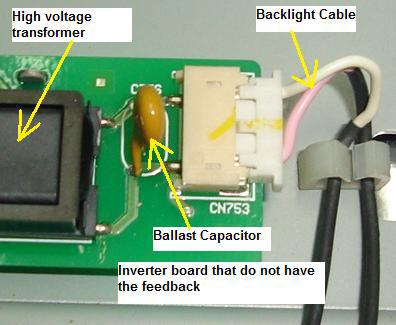
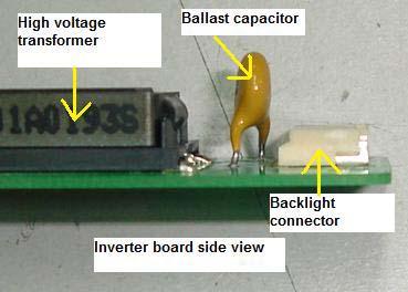
36 Buck Royer Inverter Schematic in LCD Monitor In order to drive the Backlights (CCFL lamps) embedded in the panel module, an inverter circuit is required to convert the 12 volt DC up to hundreds or even a thousand plus AC voltage output. The inverter is formed by symmetric circuitry, in order to drive the separate lamp modules. The input stage (buck converter circuit) consists of Inverter IC (PWM IC), Buck P-channel FET, Buck Choke and Buck Diode. The Buck converter circuit converts a DC voltage to a lower DC voltage. The other stage consists of a tuning capacitors, high voltage transformer, and push-pull transistor pair to boost ac output to hundreds of voltage. The ballast capacitor controls current amplitude through the lamp negative impedance by dropping an approximately equal voltage across its positive impedance. The feedback circuit is for protection purposes and will shut down the inverter IC just in case if the high voltage produced by the high voltage transformer exceeded the normal value and also it can detect bad or a flicker backlights. The inverter IC also used to control the brightness of the CCFL lamps. The AC frequency of the high voltage transformer is typically run at 30 to 70 KHz. The higher the frequency, the greater is the light output. Note: Some LCD Monitor design has the Buck type P-channel FET integrated into an IC thus in order to successfully testing them you can use the comparison method with another known good FET (comparing the ohms value between pins) or by using the Peak Atlas Analyzer test equipment. The IC can be in Dual in Line package or SMD type. 36


37 The above two IC s can have one or two Mosfet in it. 37

38 It is easy to test the FET that already integrated into IC with Peak Atlas Analyzer The common Buck P-channel FET is FU9024N, J598 and etc. The SMD FET IC s are 4431, BE3V1J and etc. The common push pull transistors part numbers are C5706, C5707 and etc. 2) Push Pull Inverter (Direct Drive) The push pull inverter shown above when Q1 switches on, current flows through the 'upper' half of T1's primary and the magnetic field in T1 expands. The expanding magnetic field in T1 induces a voltage across T1 38
, Q2 conducts, current flows through the 'lower' half of")
39 secondary. When Q1 turns off, the magnetic field in T1 collapses and after a period of dead time (dependent on the duty cycle of the PWM drive signal), Q2 conducts, current flows through the 'lower' half of T1's primary and the magnetic field in T1 expand. Now the direction of the magnetic flux is opposite to that produced when Q1 conducted. The expanding magnetic field induces a voltage across T1 secondary. After a period of dead time, Q1 conducts and the cycle repeats. The above diagram only showing a single channel IC that is driving the Q1 and Q2. Some inverter IC can have two channels in order to drive two high voltage transformers. Each output from the transformer can drive more than one lamp. Please take note of this! 3) Half Bridge Inverter (Direct Drive) The half bridge inverter is similar to the push pull inverter, but a centre tapped primary is not required. The reversal of the magnetic field is achieved by reversing the direction of the primary winding current flow. This type of inverter is found in many LCD Monitor too. The control circuit of a half bridge inverter is similar to that of a push-pull inverter. This design has optimal utilization of transformer core and primary winding (one vs. two for push pull). The above diagram only showing a single channel IC that is driving the Q1 and Q2. Some inverter IC can have two channels in order to drive two high voltage transformers. 39

 Full")
40 Each output from the transformer can drive more than one lamp. Please take note of this too! A Half Bridge inverter schematic 4) Full Bridge Inverter (Direct Drive) 40

41 The full bridge inverter is similar to the push pull inverter, but a centre tapped primary is not required. The reversal of the magnetic field is achieved by reversing the direction of the primary winding current flow. This type of inverter is found in many latest LCD Monitors. Diagonal pairs of transistors will alternately conduct, thus achieving current reversal in the transformer primary. This can be illustrated as follows - with Q1 and Q4 conducting, current flow will be 'downwards' through the transformer primary and with Q2 and Q3 conducting, and current flow will be 'upwards' through the transformer primary. The control circuit monitors V out and controls the duty cycle of the drive waveform to Q1, Q2, Q3 and Q4. The control circuit operates in the same manner as for the push-pull inverter and half-bridge inverter, except that four transistors (FET) are being driven rather than two. In some LCD Monitor like the HP1703 that uses the OZ960 inverter IC, the output from inverter IC can parallel out to drive another high voltage transformer as seen from the picture in the next page. A Full Bridge Inverter Board 41
) in it. Two IC s were used to drive each high voltage transformer.")

42 The full bridge inverter design has 4 IC s (each IC have two FET (N and P channel)) in it. Two IC s were used to drive each high voltage transformer. A Dual N and P channel PowerTrench Mosfet IC Remember that the dual N and P channel PowerTrench Mosfet IC can be in SMD type or Dual in Line package. 42
43 Common faults found in inverter board 1) Dry Joints (Very common in the buck choke and high voltage transformer pins) 2) Shorted or burnt high voltage transformers 3) Shorted or leaky push pull transistors 4) Capacitance value open (out) in tuning capacitors 5) Shorted buck P-channel FET 6) Inverter Pico fuse open circuit or turned high ohm 7) Ballast capacitors value out causing shutdown and brightness fluctuate 8) Burnt pins or loose connection in the backlights connector Surprisingly the inverter IC s are very robust and seldom fail. Some common part numbers for inverter IC s are TL1451ACN, 0Z960, 0Z962, 0Z965, BIT3105, BIT3106, TL5001 and etc. In order to measure the voltage and waveform in the inverter board please refer to the chapter of LCD Monitor Critical Voltage and Waveform Test Points. 43
.")
44 Understanding the Start Circuit Most of the LCD Monitor has a Start Circuit to control the voltage from the power supply to the supply pin of Inverter IC. The main control signal comes from the Main board and the voltage is from 0 and few Volts (2-5 Volts). If the signal is Zero Volts, then the inverter IC would not receive any supply voltage from the power supply and if the signal is 2 Volts (On) then the inverter IC would be On and the high voltage transformer would energized and the backlights will light up. The Start Circuit is a good starting point to diagnose why the LCD Monitor has no display, display shutdown and intermittent no display problem. Showing the On/Off marking in Inverter Board 44
 the Main board would first send out an On (BL-ON) signal (about 2 to 5 Volts")
45 Let s take a look from the schematic diagram below how this Start Circuit works. Whenever a good LCD Monitor is turn ON (assuming the VGA connector is already plugged into the Computer system CPU) the Main board would first send out an On (BL-ON) signal (about 2 to 5 Volts depending on the LCD Monitor designs) to the base of Q751. The ON signal caused the Q751 to turn ON and this lead to Q752 also ON. Thus the 12 Volts could flow from the emitter and out at the collector pin and reach the VCC (supply) pin of TL1451ACN (Inverter IC). F751 is a Pico fuse (some is SMD fuse) and rated at 2 Amp 125 Volt. A Start Circuit Schematic in LCD Monitor If the Main board didn t send the ON signal (due to problems in Main board) to the base of Q751, the transistor Q752 would not turn On thus no voltage will flow to the VCC (supply) pin of the inverter IC causing no display in LCD Monitor. 45
 as shown in the picture below. Both transistors are digital transistors and it have resistors (4k7 + 4k7) built into the transistor.")
46 Typical Start Circuit in LCD Monitor Other designs may use the C945 and A733 as the combination pair in Start Circuit while some design like the Samsung 153V used the A6J (PNP digital transistor) and the A8J (NPN digital transistor) as shown in the picture below. Both transistors are digital transistors and it have resistors (4k7 + 4k7) built into the transistor. Example of Digital transistors I received many s asked about how to diagnose LCD Monitor problem that have power but with no display symptom. Actually it is very easy to check if the problem is in the Main board, Start Circuit or even in the inverter IC itself. 46


47 Place the red probe of your digital meter to the On/off pin as shown in the photo below then the black probe to any cold ground. Now switch ON the LCD Monitor and look at the voltage. If there is a voltage (say 2 to 5 Volts) you can confirm that the Main board is working and sending a right signal. If no voltage measured by the meter then this indicates the Main board is having problem. Samsung LCD Monitor with the models of 153V, 173V, 510N, 710N, 713N and 910N are very famous for no display problem (not sending the On signal) and intermittent no display problem and was caused by a failure in the microcontroller (MCU). Another Start circuit in LCD Monitor 47
48 Next if there is an ON signal then expects about 9 to 12 Volts at the VCC supply pin of inverter IC. If there are input signal to the base of the Start Circuit transistor and no output to the inverter supply pin, suspect defective components in the Start Circuit area or even a faulty Pico fuse preventing the supply voltage from flowing to the inverter IC. Do not overlook that a shorted inverter IC may pulling down the supply voltage to a very low value if the fuse did not open circuit. If possible, direct replace the inverter IC and retest the LCD Monitor again. For an intermittent no display problem you could actually see from your meter that the On/off signal voltage is rising and falling and this is a clear sign of the microcontroller (MCU) fault. Do more practical testing on a good LCD Monitors and it would not take you long to find out if the fault is in the Main board, Start circuit or in the inverter circuit area. 48


49 Understanding the BackLight (Lamps) Cold Cathode Tube Or CCFL The LCD panel itself cannot emit light. Therefore, a backlight system that supplies the light from behind is normally required. The backlight system consists of a light emitting device that produces light, a conductor panel that distributes the light to the entire LCD surface uniformly, and a power supply that drives the light emitting device. Backlights can comes in many types of lengths and shapes too. 49

50 Internal Parts in LCD Monitor Currently, the most commonly used light emitting device is a fluorescent tube called a cold cathode tube or CCFL. The CCFL is called a cold cathode tube because even though the principle of illumination is the same as that of the hot cathode tubes used by indoor lamps, this lamp does not require preheating of the filament. Also, the electrodes at the end of the bulb stay at a low temperature while emitting light. CCFL also enjoy a long life (approx 50,000 hours) without serious degradation. A special power supply, inverter, which generates approximately 600 to 1000 AC is required to drive a CCFL. This inverter is a small power supply used to make this CCFL illuminate, and is one of the important functional parts of a complete LCD display. Display Flicker and Reddish Normally a reddish display and display flicker in LCD Monitor were caused by one of the defective backlight (either top or bottom backlight). For those LCD Monitors that do not have the feedback circuit in the inverter board, even though the backlight have problem the LCD Monitor continue to work and never shutdown. This is totally different in LCD Monitors that have the feedback circuit in the inverter board because even a slight flicker in the display caused by a defective backlight, the LCD Monitor would immediately shutdown. 50


51 Showing the dark end in LCD Monitor backlight 51

52 52


53 Replacing Backlight The right way to retrieve a backlight from the LCD panel In order to successfully replace the backlight you must gently pull out the backlight together with its casing as shown in the photo above. Some backlight can be easily removed while some were tough. For those backlight that had been totally sealed up, you must be careful when retrieving the back light. 53
54 I once accidentally torn off the tape carrier package (TCP) when removing a backlight and the LCD panel can t be use anymore because the display has a thick black bar at the side of the display. The TCP is very fragile and you should put more attention to it when you try to disassemble the LCD panel in order to check or replace the backlight. Once the TCP broken there is no way to repair it Questions related to the backlight 1) How do we know if a backlight is good or bad? By using another known good backlight either from a new backlight you bought as a spare or from another working LCD Monitor. If the backlight connector is compatible, just connect it and test. If the display is reddish or have flicker chances are high is the backlight fault. Again you have to remove the backlight and see if there is any dark end or not. 54
55 2) Can I install a 15 backlight into a 17 LCD Monitor? Yes you can, but the top and bottom display would not properly covered up (due to the 15 backlight is shorter than a 17 backlight) and you could see some darker area at the edge of the display. 3) Can I replace a backlight from other brands of same size LCD Monitors (assuming from a 15 to 15 LCD Monitor)? Yes, you definitely can but again you have to check the intensity of the backlight from other LCD Monitor even though it is the same size of Monitor. If the replacement looks a little bit darker compare to the original backlight (assuming you have replaced the top backlight) then I guess you have to replace the bottom backlight too (even though the bottom backlight is good) for balance of light intensity purposes. You can keep the bottom backlight (the good backlight) for future use. 4) At where I can order LCD Monitor backlights? You may check out the websites at the recommended resources in the last chapter of this book. 5) Should I buy some of the backlights and keep? It depends on your budget; you can order some to keep as spare and troubleshooting purposes. There would be no waiting time if you come across LCD Monitors that have backlight problem. Extra backlights may also help you to diagnose a problem fast. You will immediately know if the LCD Monitor problems like display shutdown, flicker, reddish, dim and etc were cause by a faulty backlight or not by replacing with a known good working backlight. Secret Tips How To Solve Display Flicker Without Replacing The BackLight Normally in a newer design of LCD Monitor (that have feedback circuit) when a display flicker (even very slight flicker) the display would immediately went into shutdown. This could happen especially to LCD Monitors that is using the OZ960 series inverter IC. Carefully observe from the screen at where the flicker starts first. If it start from 55

56 the top and spread to the bottom suspect a faulty top backlight. If it start from the bottom and spread to the top portion of the screen suspect a bad bottom backlight. Yes you can actually see at where the flickering starts first but with one condition, you have to focus and pay attention on the screen even if it takes you sometime. Once you have locate the defective backlight (assuming the top backlight) you will then replace it with a new backlight am I right? Well it is not always the case, sometimes for a minor flicker backlight problem you can actually modify the feedback circuit to make the LCD Monitor to continue to run without shutting down. The inverter board How I suppose to modify the feedback circuit? Trace from the bottom backlight feedback circuit and look for any resistor that goes to cold ground. Remove that resistor and replace it with a preset. Switch On the Monitor and tune till it don t shutdown anymore. 56


57 True case example A HP1702 LCD Monitor came in with slight flicker problem at the top backlight. I traced from the feedback circuit and found a resistor (R120) that connects to cold ground. I replaced it with a 1Kilo Ohm preset and switch On the Monitor. Then I tune the preset until it don t shutdown anymore. I remove the preset and measure the Ohm 57


58 value and it reads 238 Ohm. I then replace the preset with a 240 Ohm resistor and the LCD Monitor worked beautifully with no more flickering! However if the LCD Monitor have a very bad flickering and reddish the only way is to replace it with a new backlight. Warning! Please do not touch on a broken lamp with bare hands as it contains mercury. Mercury is known to be very poisonous to our human body! 58
, Polarizer, Diffuser film, Light Guide Plate and Reflector film. The whole purpose of the LCD panel is to controls light throughout using the liquid crystal material.")
59 Understanding LCD Monitor Panel The LCD panel consists of Mechanical frame, Controller board, Tape carrier package (TCP), Tape Automatic Bonding, LCD Driver IC s, Backlights (lamps), Polarizer, Diffuser film, Light Guide Plate and Reflector film. The whole purpose of the LCD panel is to controls light throughout using the liquid crystal material. 59

60 Mechanical frame Provides mechanical housing to hold LCD panel and to help in reducing the electromagnetic interference (EMI). Controller Board The purpose of the Controller board is to accept additional display information from the MAIN Board and then drive the column driver transistors and row driver transistors as to which pixel in the LCD panel should light or off. These driver transistors in the LCD panel are operated by digital control signals generated by the LCD driver IC and controlled by the Controller IC. 60


61 Tape Carrier Package Tape Carrier Package (TCP) package provides both mechanical and electrical support to the LCD driver semiconductors (IC s) between the LCD panel and the driving module for the application in flat panel displays. 61

62 Tape Automatic Bonding (TAB) Tape Automated Bonding is an interconnect technology between the substrate (In LCD Screen) and the IC (in TCP); using a prefabricated carrier with copper leads adapted to the IC pads instead of single wires. Backlight Generate a consistent, uniform light source. The light generated from the backlight focused through the LCD. Polarizer A polarizer is a thin film that allows light to pass in only one orientation. In between the polarizer films contains the Colour filter, Colour filter glass, Liquid Crystal and TFT glass. 62
 Light guide plates uniformly distribute light from the backlights, which are installed at the top and bottom of displays, over the entire screen.")
63 Photo source (Courtesy from Samsung Electronics) Diffuser film Diffusion films are used in the manufacture of LCD panels to ensure that the display illumination is uniform, with as much light as possible reaching the viewer. Light Guide Plate (LGP) Light guide plates uniformly distribute light from the backlights, which are installed at the top and bottom of displays, over the entire screen. 63
64 Reflector Film Receive light from Backlights to redirect the light into the light guide plate. Replacement of LCD Panel If the LCD panel has problems such as cracked, white display, rainbow colours, bad controller board, one or few vertical lines, big horizontal black bar across screen, broken TCP and etc, the only way to solve it is to replace with a similar type of LCD panel. You can t replace with a different type of LCD panel because the specification is different in terms of connectors, signal flows, voltage and etc. That s why it is wise to buy over LCD Monitors that was beyond repair (bad power supply or inverter but with a good LCD panel) from your customers. Most of my customers would sell it if you can offer them a much higher price. 64
65 LCD Monitor Factory Service Mode Most LCD Monitors have factory service mode. So what is exactly factory service mode? When Monitor manufacturers design the LCD Monitor, they designed two types of control i.e. one for the end user to control the display setting (the front panel button in LCD Monitor) and the other control are reserve for the manufacturers to do the internal settings. What are the internal settings in LCD Monitor? Some LCD Monitors have lots of internal settings while to some there are only a few ordinary functions. RGB colours balance, position, size, languages, information (hours used) in backlights and LCD panel and etc. What are the consequences if you have wrongly changed the settings in the factory service mode? If you have mistakenly set the wrong setting in the factory service mode you may end up ruin the display (due to data lost and etc). We as a repair technician have to hold responsibility if the internal settings has gone out of value! Therefore it is advisable to write down the original value first before changing the setting in any LCD Monitors. If you are not sure about the functions settings then please do not change the value setting. What are the benefits of using the Factory Service Mode on LCD Monitor? a) You can check the accumulation time (hours) of how long a particular LCD Monitor have been used like the backlights and LCD panel. This will surely benefit to those who wants to buy the second hand or refurbish LCD Monitor provided if he or she knows how to go into the factory service mode. In general the less time (hours) that LCD Monitor used, it is better for a longer lasting operation. b) You also can check the LCD Monitor manufacturer date. This will let you know when you buy a new LCD Monitor; if is it a new model/version or vice versa. By the way not all factory service modes will display the manufacturer date. 65

66 c) You can find out the LCD panel model/part number from the factory service mode. This save your time because you can directly place an order for a new LCD panel without dissembles the whole LCD Monitor unit in order to get the model/part number. Again, not all LCD Monitor factory service modes will display such information. d) If you have reprogrammed the EEprom IC with a programmer and find out that there are still some dissatisfaction in the quality of the picture (like unbalance in colours, position and size) you can always use the factory service modes to adjust the settings until you are satisfy with the display. Will Factory Service Modes solve the no display, display shutdown and display shaking problems? No, those problems mentioned above were due to electronic circuit fault (in the power, main board, inverter and LCD panel) and it can t be solved by the factory service modes! How do we enter into the factory service mode in LCD Monitors? Different manufacturers have different way to enter into the Factory Service Modes. The login Factory Service Modes information are available only to the service technicians and engineers in the manufacturers and also to the authorized service centres but sometimes you can try login by pressing certain keys in the front panel control of the LCD Monitor. Below are the pictures that I have taken to guide you on how to enter into the Factory Service Modes for Samsung 510N LCD Monitor. 66


67 Here you are the Samsung 510N Factory Service Mode. You can try this setting on other Samsung LCD Monitor models. 67
, the LCD panel model number (INNO.VO), colour settings and etc.")
68 The above photo is for the ACER AL1916W Factory Service Modes. You could see lots of useful functions in it such as how long the LCD Monitor already in used (203 hours), the LCD panel model number (INNO.VO), colour settings and etc. Note: Different LCD Monitor brands have different way to enter into the Factory Service Modes. You can either visit electronic repair forum to ask for the login details or get the LCD Monitor training manuals that have the login information or from your electronic repair friends. 68

69 Different Between Plasma and LCD Plasma Panel A Samsung Plasma TV Plasma displays are comprised of hundreds of thousands of gas-filled cells (argon, neon, and xenon) sandwiched between two sheets of glass or clear plastic. In a Plasma TV, the panel itself emit light, so the entire screen produces bright images with deep, expressive blacks under typical living room lighting conditions. The phosphoric elements lifetime in Plasma TV has been extended in recent years to give them a practical duration of up to 60,000 hours. That's eights hours of daily operation for more than 20 years before the screen reaches half of its original brightness. Plasmas also offer an advantage in colour saturation. Each pixel contains its own red, green, and blue elements, so they have what is referred to as very accurate chromaticity coordinates. Technically, resolution is limited on smaller plasma displays. Each cell, with its red, green, and blue phosphors, acts as an individual pixel. The necessary size of these cells means only the largest plasma screens can present a true native high-definition resolution of pixels. Recent plasma screens have caught up to LCDs in contrast ratio (the measure of the relationship between darkest black to brightest white), thanks to newly developed internal algorithms that block the power going to particular pixels in order to render a pixel truly dark. This can produce contrast ratios up to 10,000:1 in the latest models. The light-blocking technology of commercial LCDs has kept them limited to contrast ratios of 1200:1, although consumer versions will soon top 1600:1. This can be important or not: The impact on the viewer depends upon additional 69

70 factors such as overall brightness and ambient light. Tests have shown that even when looking at a contrast ratio of 700:1, most people's eyes are satisfied with the apparent level of blackness. LCD Panel Humax LCD TV LCDs pack more pixels per square inch, so they can attain higher resolutions on smaller screens. LCD screens use a matrix of tiny liquid crystal cells sandwiched between sheets of glass or clear plastic, with a matrix of thin film transistors (TFTs) supplying voltage to the cells. When electrically charged, the crystals untwist to pass light from a source behind them. Depending on the degree of the twist, or polarization, the crystals block out specific parts of the colour spectrum the white light generates until they produce the desired colour by a process of subtraction. The white light source can be replaced when it grows dim, so the lifespan of LCD displays can be extended. Recent advances in LCD substrate material have also increased the practical viewing angle to between 130 degrees to 140 degrees. Some of the latest models can reach 170 degrees, which rivals the viewing angle of most plasma screens. 70

71 Tools and Test Equipment Tools In order to successfully repair LCD Monitors, you need some extra tools to help to repair the LCD Monitor fast. Here are just some of the tools that you must have in your technical department: Tweezers- Use it to hold on those SMD components so that it won t easily slip away from your repair bench. Our fingers are just too big for these little components. Thin and Strong Metal plate- Use it to easily open up LCD Monitor cover. Please do not use a normal screw driver to force open the LCD cover as it may cause the plastic cover to have a mark on it. The best is to 71


72 split open a good tweezers into half. Buy a good quality tweezers because some cheap tweezers metal can bend over when you try open up the LCD cover. Magnifying Glass- If possible get a x10 magnifying glass with LED light built into it. This tool is important to identify SMD component marking on top of its body. Without magnifying glass, you will have difficulty to recognize the coding of the SMD components. 72


73 A binocular microscope If you have the budget you may get a more powerful magnifying glass like the binocular microscope. Automobile Light Bulb- You will need the car rear light bulb to isolate problem in LCD power supply. Get a 12 volts and a 24 volts rear light bulb to easily find out the faults in any LCD power supply problem fast. 73


74 Small Set of Screw Drivers- Most LCD Monitor panel have very small screws used to cover the driver board. You need a set of small screw drivers in order to successfully open up the casing. Fishing Tackle Box- Yes, you may use a fishing tackle box or whatever box you found it to be good in storing all the tools for easy access when comes to troubleshooting and repairing LCD Monitor or even Motherboard. SMD Rework Station- This is a must tool for you to troubleshoot LCD Monitors. Removing and resoldering SMD components need this specialize tool. Do you know that a SMD rework station can solve of lots of SMD components dry joint in the PCB? 74


75 Test Equipment Besides having the basic test equipment such as the analogue and digital meter, digital capacitance meter, ESR meter, Flyback tester and oscilloscope, you will also need these specialize test equipment to easily identify faults in SMD components. The test equipment that I m referring to is Peak Atlas Component Analyzer and the Smart Tweezers. With such testers you will surely have more confident in repairing LCD Monitors. A Peak Atlas Component Analyzer A Smart Tweezers 75
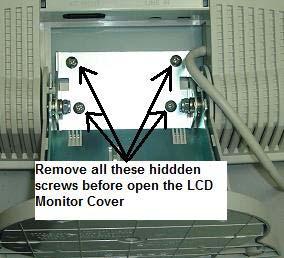
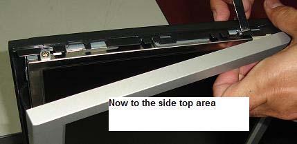
76 Secret Of Opening LCD Monitor Cover In order to successfully open LCD Monitors without leaving a mark or dent on the plastic cover, you must use a flat, wide and strong metal. Do not use a screw driver to open the cover as it would definitely leave a deep mark on the plastic cover. The plastic cover is not that really hard and the moment you use a screw driver to peel out the cover, the soft plastic would be dented. The metal you can actually use one from a split tweezers. Do not get a cheap tweezers as the material is quite soft and would not hold on at tight LCD Monitor cover. Buy a quality tweezers and break open it into two and use the end to peel off the cover. Always start to remove LCD Monitor cover from the bottom. Make sure you have removed the STAND of the LCD Monitor before you try open up the cover. Many LCD Monitor screws were located behind the STAND-so be aware of this. Once the bottom corner cover had been removed, you then can start to peel off the cover at the side and eventually to the top and another side of the cover. In some LCD Monitors, you can use both of your hands to gently (but with a little bit of pressure) to remove the side cover. Look at the photos next page for easy reference. 76


77 77


78 78


79 79


80 80

81 Understanding SMD Resistor Codes and Testing SMD resistor Understanding SMD resistor code is very important if you want to be able to repair LCD Monitors. Each SMD resistor has a numeric number on top of its body. It would not take you a long time to understand it as the below guidance will show you exactly how you can calculate the ohms value easily. 0= Jumper 000= Jumper 6R8= 6.8 Ohm 100= 10 Ohm 81


82 750= 75 Ohm 101= 100 Ohm 164= = 160 Kilo Ohm 472= 4.7 Kilo Ohm 1200= 120 Ohm 1201=1200 Ohm= 1.2 Kilo Ohm 1001=1000 Ohm= 1 Kilo Ohm 2000= 200 Ohm 1182= 11800= 11.8 Kilo ohm 1003= = 1 Mega Ohm These SMD resistor coding is the same as the SMD network resistor. SMD network resistor is actually consisting of few resistors that have same ohms value in a single package. A SMD network resistor The A512 means there are four 5.1 K ohm resistors inside the package. 82
.")


83 Testing SMD resistor The testing method is the same as when you check the normal type of resistor (carbon film, wire wound and etc). Calculate the SMD resistor code first, once you have the value then only you test it with a digital meter. Please do not use analogue meter as it won t show an accurate reading compare to digital meter. Place the test probes across the two ends of the SMD resistor on board and read the result directly from the digital meter LCD display. Sometimes checking on board won t give you an exact reading due to 83
 in the Main board but not in power supply board.")
84 back circuits thus you have to remove it out from the board with either a solder gun or with the help of a rework station. Usually SMD resistor is very robust (rarely give problem) in the Main board but not in power supply board. Certain brands of LCD Monitor power supply board do use SMD resistors and once if there is any problems in the power supply (surge, short circuit and etc); some of the SMD resistors may get burnt! Once the SMD resistor burnt, the only way to find out the value is through schematic diagram and comparison from the same LCD Monitor model. You may call up your repair friends to ask if they have the same model of Monitor or not to find out the real value of the burnt resistor. 84

85 Understanding SMD Capacitors Codes and Testing The capacitive value is indicated on the surface of the component, using body colour and one letter, or one letter and one number. For example, a leadless capacitor with a red body and coded with the letter A is a 1-pF capacitor. If the body was black with the letter A, it equals 10pF. Pentax Leadless Capacitor Values. A Colour Alphabet BODY COLOUR ALPHABET VALUE Red A C E G J L N Q S 1 (pf) 2 (pf) 3 (pf) 4 (pf) 5 (pf) 6 (pf) 7 (pf) 8 (pf) 9 (pf) 85
86 Black Red Black A C E G J L N Q S U W Y EXAMPLE: A A 10 (pf) 12 (pf) 15 (pf) 18 (pf) 22 (pf) 27 (pf) 33 (pf) 39 (pf) 47 (pf) 56 (pf) 68 (pf) 82 (pf) 1 (pf) 10 (pf) Pentax Standart two place code. = 2.2 x 10³ (1000) Examples = 2200 pf S2 = 4.7 x 100 = 470 pf J3 b0 = 3.5 x 1.0 = 3.5 pf Multiplier (0 9) Value (1 st & 2 nd sig. digits) Value (33 value symbols ) upper-and lowercase letters A B C D E F G H J K a L M N b p Q d R e S f T U m V W n X t Y y Z Multiplier 0 = x = x 10 2 = x = x = x
 uppercase letters only A B C D - - - - 10 11 12 13 F G H J K E - 15 5 = x 100000 etc.")
87 Samsung Alternate two code numbers. -Values below 100 pf- Value Read Directly 05 -Values 100 pf and above-letter/number code = 5 pf = 10 x 10 A1 = 100 pf Multiplier (1-9) Value 1 st & 2 nd sig. digits 82 = 33 x 1000 = 82 pf = pf = 0.33 mf N3 Value (24 value symbols) uppercase letters only A B C D F G H J K E = x etc L M N P Q R S T U V W X Y Z Multiplier 1 = x 10 2 = x = x = x
88 Samsung standard single place code of chip capacitors. pf W (ORANGE) = 4.7 x 1.0 = 4.7 pf Examples R (Green) = 3.3 x 100 = (Blue) = 8.2 x 1000 = 8200 pf Colour - multiplier Symbol-value Value (33 value symbols) upper-and lowercase letters A B C D E H I J K L N O R S T V W X Y Z Multiplier ORANGE = x 1.0 BLACK = x 10 GREEN = x 100 BLUE = x 1000 VIOLET = x RED = x The above tables for SMD capacitor codes were only limited to their own brands. Others manufacturers have their own code thus making us as a repair technician have difficulties in finding the SMD capacitor value. There is one way where you can find out the capacitor value. Assuming you found a red colour SMD capacitor shorted in a LCD Monitor Main board, what you can do next is to look around the surrounding circuit for the same size and same colour of the SMD capacitor. Remove it out from the circuit and measure the capacitor value; once you got the value you can then replace a new capacitor on the shorted red colour SMD capacitor. I have done that before and it worked! 88

89 Testing SMD capacitor There are few ways you can test a SMD capacitor found in LCD Monitor board. The first way is to use specialize test equipment that was designed to test SMD components like the famous Smart Tweezers by AdvanceDevices.com. Smart Tweezers Just place the tips across the SMD capacitor and you can read directly from the LCD display. I found that the result were not that accurate when measuring the SMD capacitors on board most probably due to back circuits and you need to solder it out and test off board for accurate reading. 89


90 Testing a SMD capacitor On board with Smart Tweezers Next, we have the digital capacitance meter to check the SMD capacitor values. In order to get a good result we have to solder it out and test. Place the probes across the SMD capacitor, select the proper capacitance range and read from the LCD display. The only disadvantage using this way to test SMD capacitor is the probes are too big for the small component. Anyway it should not be a problem to us as electronic repairer as we could easily modify the probes to test the tiny components. Sometimes by measuring only the capacitance value will not guarantee that the capacitor is good and you need to perform another test to make 90

91 sure that the capacitor is not breaking down when under full load. How are we going to do that? The third testing method will answer your question. By using analogue meter set to X10 K Ohms we can accurately test SMD capacitors that breakdown when under full operating voltage. Just place your test probes across the capacitor and the pointer should not show any low ohms reading. If the capacitor value is big, it may cause the pointer to kick up a little and go back down to its original position (infinity). Swap the test probes and retest again and you will still get back the same result. This proved that the capacitor is working fine! Take note: No matter what types of SMD capacitor you are measuring, the pointer should not stay at low ohms reading either way (test probes) you test it with analogue meter. Conclusion- In order to successfully confirm that a SMD capacitor is good, you must perform two tests; first is to measure the capacitance value and the other one is to check the capacitor with analogue meter set to X10 K ohm and make sure it is not shorted. 91


92 Understanding SMD Transistor and Diode Codes and Testing In order to successfully test SMD transistor and diodes, you first need to find out the meaning of the codes printed on the devices. A 3 legs SMD diode you may think is a transistor. A digital transistor you may think it is a normal transistor and so on. If you do not know the meaning of the codes, I believe you will have a hard time to test the components. A good component you may think it is bad and this will eventually cause you to lose more of your troubleshooting time in electronic repair. 92
93 Below are just some of the SMD transistor and diode codes specification. In the market there are lots of SMD codes and markings on the components thus this notes can t covers all of the codes. You have to visit this website for reference and look for any updates on the SMD codes. Once you know what type of components the codes belongs to, then you can use the necessary testing method to check it. Code Device Name Manufacturer Base Package Leaded Equivalent / Data A BA892 Sie I SCD80 35V 100mA pin A 1SS355 Roh I USM 100V 50mA sw A MRF947 Mot N SOT323 npn RF 8 GHz A-Q 2PD1820AQ Phi N SOT323 gp sw amp 50V npn hfe A-Q 2PD1820AR Phi N SOT323 gp sw amp 50V npn hfe A-S 2PD1820AS Phi N SOT323 gp sw amp 50V npn hfe A0 HSMS-2800 HP C SOT23 HP2800 schottky A0 HSMS-280B HP C SOT323 HP2800 schottky A03 VAM-03 MC AQ - modamp MAR 3 Similar A06 VAM-06 MC AQ - modamp MAR 6 Similar A07 VAM-07 MC AQ - modamp MAR 7 Similar A1 HSMS-2801 HP K - HP2800 schottky A1 BAW56W Phi A SOT323 dual ca BAW62 (1N4148) A1 BAW56 Phi A SOT23 High-speed double diode A1 BAW56W Phi A SOT323 High-speed double diode A1 BAW56T Phi A SOT416 High-speed double diode A11 MMBD1501A Fch C SOT23 180V 200mA diode A13 MMBD1503A Fch D SOT23 180V 200mA dual diode series A14 MMBD1504A Fch B SOT23 180V 200mA dual diode cc A15 MMBD1505A Fch A SOT23 180V 200mA dual diode ca A16 ZC934A Zet C SOT pF hyperabrupt varicap A17 ZC933A Zet C SOT pF hyperabrupt varicap A1p BAW56 Phi A SOT23 High-speed double diode A1s BAW56W Sie A SOT323 dual ca BAW62 (1N4148) A1s BAW56 Sie A SOT23 dual ca BAW62 (1N4148) A1s BAW56U Inf A SC74 dual ca BAW62 (1N4148) A1s BAW56 Inf A SOT23 Common Anode A1s BAW56T Inf A SC75 Common Anode A1s BAW56W Inf A SOT323 Common Anode A1s BAW56S Inf DA SOT363 Double Common Anode Testing SMD Transistor Testing SMD transistor is a little bit different from testing normal bipolar transistor because lots of SMD transistors are from the digital transistor family where internally it has additional resistors causing the reading from your analogue multimeter to be different. 93

94 A PNP Digital Transistor (observe the two resistors in the package) A SOT-323 package for SMD Transistor The only way to test it is through comparison and you have to compare with the same part number. 94


95 Testing Diode A 1N4148 SMD Diode 1N4000 series SMD Diode Set to X10K Ohm to test SMD diode Checking SMD diode is just like testing normal silicon diode. You have to use analogue meter set to X10 K ohm to test SMD diode. A good SMD diode should have one reading and if you get two reading that means the diode already shorted. You also have to beware that SMD Schottky diode would have two reading but not shorted reading. Please refer back to testing Schottky diode chapter to learn how to test a Schottky diode. 95
 RT9164-25CG = Voltage regulator output 2.")
96 Typical IC codes in LCD Monitor A 3.3 Volts Voltage regulator AIC = Voltage regulator output 3.3 volts (input 5 v) KA278R33 = Voltage regulator output 3.3 volts (input 5 v) RT CG = Voltage regulator output 2.5 volts LM2596 = Voltage regulator output 5 volts (input 12 v) AMC =Voltage regulator output 5 volts (input 12 v) 78M05 = Voltage regulator output 5 volts 78M12 = Voltage regulator output 5 volts APL5522KCTR = Dual output voltage regulator (pin1 =3.3v, pin 4=2.5v) input voltage 5 volts. TDA7053A= Audio amplifier IC TDA8227p= Audio Amplifier IC 96

97 TDA7496= Audio Amplifier IC 97


98 These are just some of the example of IC s code used in LCD Monitor. Due to the unending release of new LCD Monitor in the market every now and then, I suggest you to look up at the internet to refer to the latest codes for any IC s part number. You may also do your own research to find out if a device that have 3 legs is a voltage regulator or not by performing some voltage testing. Sometimes a 3 legs device could be a Mosfet so please take note on this. Note: In the future you might discover that there are 4 voltage regulator IC s in a single package since now they already have the dual voltage regulator in a single IC. Just be alert and flexible. 98
 circuit, switching regulator and etc.")

99 Schottky Diode Rectifier Application and Testing Figure 1 The Schottky diode or Schottky barrier rectifier is designed for uses in high efficiency rectification essential for applications like switched mode power supply (SMPS) circuit, switching regulator and etc. The function of Schottky diodes is to convert AC to DC voltage so that the DC voltages can be use by other circuit such as CPU, EEprom, inverter and etc. If you observe any electronic schematic diagrams and layout, Schottky rectifier symbol looks exactly the same as a normal diode. Typical Schottky Diode 99

100 Even the outlook, shape and designed just like a normal diode. The major difference between a normal diode and Schottky barrier diode is the part number. Because of the same outlook, many electronic repairers think that measuring Schottky diodes is just the same way as testing a normal diode. If you use the normal diode checking method to test on Schottky diode then chances are high that you will not solve the problem. You also find that it was quite common in LCD Monitor to see two Schottky diodes in a single package as shown in photo below. Both Schottky diodes are pointing to each other and the testing method is just the same as when you are checking a single diode. I will show you the right method to test Schottky diode so that you will not confuse anymore. Using the semiconductor data book and with the help of search engines, you will easily find out whether the diode you are checking is Schottky, normal diode, ultra fast recovery or even damper diode. In electronic repair, you should not guess what component you are measuring, just locate the data and confirmed it so that you are 100% sure what is the best methods to check it. Once you have confirmed that the diode you are going to test is a Schottky diode then you have to use the right way to measure it. Using analogue multimeter, set to X1 Ohm and place the red probe to centre pin and the black probe to either side of the pin, you should get a low ohms reading. Now reverse the probe where the black probe to centre pin and the red probe to either side of the pin and should not get any reading. If you get a reading then the Schottky diode is considered shorted. Usually it just shorted at one side and I m rarely see two Schottky diodes breakdown at the same time. 100


101 101


102 102


103 Now set your analogue meter to times 10k ohm range and put the red probe to the cathode and the black probe to the anode. You should see the pointer moved to full scale. Now, reverse the probe and you will get some leakage reading. In other words, the pointer will move up a little bit. This is the good characteristic of a Schottky diode when you get this type of reading. However if you test a normal diode using the X10 K Ohms range and you discovered that it has two readings then the diode is said to be defect and need replacement. 103

104 A shorted Schottky barriers diode will show two full scale readings registered at the meter of the panel. Assuming if an electronic repairer don t know how to test a Schottky diode, he or she may think that the leakage reading at X10 K Ohm means a defective diode. Sometimes replacing a Schottky with a normal diode may cause the equipment to be unstable especially in the sensitive circuit. The best is to replace with original part number or a specification that is higher voltage and current than or same spec with the original diode. Typical part numbers for Schottky diodes are SBL1040CT, STPR10, SB530 and etc. Refer to your favourite semiconductor replacement book for datasheet and find out the specification of these part numbers. If you have one, try testing it with your analogue meter and you will be surprised that there are two readings at X10K Ohm but not shorted reading. By the way the failure in Schottky diodes were quite common thus you have to know what you are measuring. 104
. This can often be fixed. What is a stuck pixel? A stuck pixel is a common pixel defect on LCD screens.")

105 Stuck and Dead Pixel in LCD Monitors If you come across LCD Monitors that has a stuck or dead pixel (a point on the screen that is always lit or always dark), it is usually due to a transistor malfunction or uneven distribution of liquid in the liquid crystal display (TFT LCD). This can often be fixed. What is a stuck pixel? A stuck pixel is a common pixel defect on LCD screens. A stuck pixel is a bright dot of colour on a screen which emits colour when it is not supposed to. Stuck pixels are most easily noticed on dark or black screens where it will appear red, green, blue, or any combination of the three colours including yellow, purple or even white. Solid red, green, or blue, are the most common stuck pixels. Many people often falsely labelled stuck pixel as dead pixel, whose one of the three sub-pixels are permanently off, producing a black pixel. Stuck pixels are common on LCD Monitors, LCD televisions and portable devices such as PSP Play station. Each pixel on an LCD screen 105

106 is composed of three cells (sub-pixels), one red, one green, and one blue, which produce the visible colour of the pixel by their relative brightness. A stuck pixel results from a manufacturing defect which leaves one or more of these cells turned on. Stuck pixels are not easily noticeable on a white background and you need to make sure that the background is dark (black) in order to locate stuck pixel. Visit this website to turn your LCD Monitor to any background you prefer. How to fix stuck pixel? Pressure Method 1. Turn On the LCD Monitor and display a black image so that you can clearly locate where the stuck pixel is. 2. Use a damp washcloth and fold the washcloth around your finger so that when pressure is applied, you won t scratch the screen. 3. Gently apply little pressure (massaging) on only the stuck pixel area otherwise you may create more stuck pixels. While still applying pressure you can turn the screen off and back On again for several times 4. Continue to apply the pressure on the stuck pixel until it totally gone (sometimes the stuck pixel may appeared again so you have to do it few more rounds). 5. If the stuck pixel is still there even after you have used the pressure method then I guess you have to use the software method. 106

107 Software Method 1. Try running pixel fixing software where you can get it at Stuck pixels can often be re-energized by rapidly turning them on and off. 2. If the stuck pixels still won t go away even after you have run the software for many hours, then it could no longer be repair and the only way is to replace the LCD panel or just send the LCD Monitor back to your customers telling them about the problem. Normally customers will accept it as one or two stuck pixels won t really affect them. If the LCD Monitor is under warranty then you have to inform your supplier about this but usually the supplier only will replace if there are more than 10 stuck or dead pixels in the LCD screen! What is a dead pixel and how to fix it? A dead pixel is a defective pixel that remains unlit on an LCD screen. Dead pixels are always black and are most noticeable on a white background. A dead pixel occurs when the transistor that activates the amount of light that shows through all three sub-pixels malfunctions and results in a permanently black pixel. Dead pixels appear black while stuck pixels can be one constant colour like red, blue or green. Dead pixels can not usually be fixed. However, you still can use the method (fixing stuck pixel) and try on dead pixel. I came across intermittent dead pixel before in IBM 15 LCD Monitor and I managed to fixed it using the pressure method-there is no harm trying it. 107


108 A Dead pixel in LCD Screen Warnings 1. Do not attempt to open the LCD Monitor as it will void the warranty and the manufacturer will not replace it. 2. Make sure you don't get any electrical equipment wet. 3. Do not apply too much pressure on LCD screen as it can break (crack) easily. 108

109 This Is How a Cracked LCD Panel Look Like LCD panel cracked due to many reasons and mostly it was caused by a fall or drop from the computer table or accidentally slipped from your hands while you are holding it. Sometimes if you are not careful and applied too much force on it while cleaning the LCD panel, it may crack also. Is there a way to repair a cracked LCD panel? For your information no one can repair cracked LCD Screen. In order to solve the LCD panel cracked problem, the best is to replace with a known good LCD panel. The LCD panel you either bought it from your repair friends who have it lying in their store room or the one you bought it cheap from your customers where the LCD Monitor was beyond repaired due to lightning strike on the power and Main board/scalar board 109


110 You may also try searching at Ebay.com to look out for any used LCD Monitor that has a good LCD panel. Replace only with the same size and model. Some LCD Monitors is OEM, for example certain DELL LCD Monitors is the same with BENQ LCD Monitor thus their boards and LCD panel can be swapped! 110
 fast because I have ready stocks but of course not the LCD panel. Warning!")
111 Usually if I come across LCD panel that was cracked I would offer my customer a certain price so that I can salvage the internal boards (power board, Main board, inverter boards and etc) and even lamps for future use. This way I can save a lot and sometimes I could repair another customer LCD Monitor (same model) fast because I have ready stocks but of course not the LCD panel. Warning! A cracked panel in BenQ 15 LCD Monitor The liquid crystal that may leak from the panel is poisonous if it enters the eyes or mouth. If any part of the skin or body parts comes in direct contact with the panel, please wash thoroughly. If some physical symptoms result, please consult your doctor. 111

112 LCD Monitor Critical Voltage Test Points Critical voltage test points are the fastest way to determine at where the faulty section or even faulty components located. Many professional electronic repairers use test points to locate fault to the exact location. Here you will have the opportunity to learn voltage testing and start to identify faulty section in LCD Monitor. Danger - Before you begin to test any points in the LCD Monitor, I highly suggest that you get help from your experienced repair friends and make sure the AC Voltage is coming from an isolation transformer (so that it can protect you just in case if there is any electrical shocked happen). Treat electricity with respect and make sure you are completely known what you are doing. Okay let s begin if you are ready! First locate the bridge rectifier and then place the test probes across the AC pins. Hold the test probes tight so that it won t slip away and touch on other pins. Since you are measuring the AC voltage the test probes can be in either way. 112


113 If you get a reading of about 230 Volts AC (in USA is 110 Volts) then this proved the presence of AC voltage from the AC outlet and the fuse is working. If it is zero volts then you have to check the circuit before the bridge rectifier. It could be a bad fuse; the AC outlet was not turned On, loose connection, broken AC cable and etc. 113

114 Testing the filter capacitor voltage Once you have confirmed that the bridge rectifier has AC supply input, you should now expect about 300 Volts DC present (for USA about 150 Volts DC) at the pin of the filter capacitor. Please make sure you hold tight to your test probes and carefully touch on the capacitor pins. If you accidentally touch the pins while doing the test, it might generate a great spark and blow the power section. If you don t have the confident to do the job get a repair friend to help you out. The black probe has to be at the negative pin side and the red probe to positive side as shown from the photo. You get DC voltage because the bridge rectifier already converted it from AC supply. If you get the expected DC voltage then move on to test the supply voltage of the power IC, if not troubleshoot the area to locate if there is any problem with the circuit like dry joints, broken track and etc. Testing the supply voltage (VCC) of power IC I m using another power board to clearly show you how to test the supply voltage of power IC. First locate the VCC pin of the power IC from the data book or from the internet. Once you have found the VCC pin, now place the red probe to the VCC pin and the black probe to HOT ground (primary filter capacitor negative pin) and switch On the power. You 114


115 should get a DC volt reading from 16 to about 20 volts (depending on LCD Monitor designs). In the below photo, we got DC volts. If you get the right voltage this mean that the bridge rectifier, filter capacitor and the start up resistors is doing its job and you should now perform the next test. Don t waste unnecessary time changing the bridge rectifier, filter capacitor or even checking the resistance value of start up resistor. 115


116 Testing the secondary output voltages It is very simple to do this test. Just place the red probe at the diode cathode side and the black probe to cold ground (the chassis ground) and power On. You should get a DC volts reading from all the secondary output diodes. 116


117 Using our common sense we can conclude that since we got the right output voltages at the secondary side, this clearly indicates that ALL the components or the primary side of the power supply is functioning. If you spend your time testing the components in the power side, you are just wasting your time. That s why there is a good advantage of performing the voltage testing to confirm which parts in the LCD Monitor is having problem. Since there is correct voltages presence at the secondary outputs, your next step would be finding faults that are located after the secondary output diodes. 117

118 Testing the voltage regulator If the output voltages are good, next you have to test the supply voltage to the Main board. Look out for a 3 pin IC and most probably it is the voltage regulator that supplying voltage to the Main IC s. Just place the red probe to the output of the voltage regulator (normally pin 3 is the output pin) and read from the meter. If it show 2.5 V or 3.3 Volt then the voltage regulator is good. If not you have to start troubleshoot backward from the input pin (pin 1) and sometimes the voltage regulator itself can be defective too! Testing the Inverter Board In order for the inverter board to function, the inverter IC must first receive a supply voltage (VCC) from the power supply. The voltage is somewhere from 12 to 16 Volts DC (depending on the design of the LCD Monitor) and also supplying to the Buck Royer circuit and the transformer. If the voltage is not present or too low for the inverter IC, the LCD Monitor would not have display (dark display) or even intermittent shut down. Thus it is important to make sure that the inverter IC must received a steady voltage from the power supply. 118


119 Place the red probe to the Pico fuse and black probe to cold ground. Read from your meter and it should have a DC volt. If there is low or no voltage, suspects the defective Pico fuse and the secondary diode or even the power supply. Sometimes a shorted component upstream (further down the electronic circuit) may have dragged down the voltage. Lift up one leg of the fuse and retest again. If you got a normal voltage then this proved that the upstream circuits or components have problem. Now, assuming if you get the right voltage at the supply pin of inverter IC then this proved that the Start Circuit and the Main board are working fine. If you get zero volt and the Pico fuse have about 12 to 16 volts then suspect a faulty Main board (not sending the On signal to Start Circuit) or even the Start Circuit itself have problem. 119


120 Testing the high voltage transformer 120

.")
121 Testing LCD Monitor high voltage transformer is like checking power supply SMPS transformer. Why it is called high voltage transformer? It is because the transformer is a step up transformer that s mean it step up AC input voltage from 10 to 20 over volts to several hundreds AC output voltage! There are 3 ways to test the transformer, you can use the resistance test or with the help of a flyback tester which is more accurate in finding shorts between winding or even you can perform the voltage test. Resistance test The primary winding have less winding thus the resistance is very low (most meters will show zero ohms). The secondary have more winding thus the resistance is higher than the primary side. Ohmmeter only showing whether is there any broken winding in it or not and it is not a 121


122 good meter to test shorted between windings turn. You need the flyback tester to test shorted between winding turns. Make sure also that you set your analogue meter to X10 Kilo Ohms to measure between the primary and the secondary winding. It has to be no reading; if you got any reading that s mean there is an internal short circuit between the primary and the secondary winding. For a burnt or shorted transformer, the only way to solve it is to replace with a new transformer. Shorted winding test Getting a good resistance measurement does not mean that the transformer is good. You need to perform the shorted winding (turn) test with a flyback tester in order to confirm that the winding is indeed good. Primary winding seldom shorted but secondary winding have the higher 122

123 chance due to more turns in it. Simply place the flyback tester across the secondary winding and read from the LED bars. Depends on transformer windings some good one will light up the 1 st LED and the second LED will blink. Some will light up the 2 nd LED and the third LED will blink and to some it will light up the 3 RD LED and the fourth LED will blink. These are the good measurement of high voltage transformer. If you get no reading at all, then most probably the transformer winding has gone shorted. You may build your own flyback tester with the help from this website: Voltage test The third test is to perform voltage measurement on the output pin of the transformer. Switch On the LCD Monitor and set your analogue meter to 1000AC range. Hold the red test probe and quickly touch on the pin of the backlight connector as shown from the photo in the next page. The moment the probe touch on the pin, you could clearly see that the meter s pointer kick up very fast. You have to release the probe fast otherwise the LCD Monitor will go into shutdown mode due to the feedback circuit had detected unusual changes in the output voltage. For the black probe just leave it and no need to connect to cold ground. If you could see the pointer moved up very fast, this is a good sign that the transformer is working fine. Again if the inverter IC have problem, the transformer would not be energized and you cannot use this method to 123


124 test it. After few LCD Monitors has come across your repair bench, I m sure you will know which methods to use to test the transformer. The Frequency Test There is another unique way to test if the inverter board or the transformer is working or not. Just place your digital meter red probe on top of the transformer and select the frequency test (make sure your meter have the capability to measure higher range of frequency) and the meter will pick up the frequency. This again proved that the transformer is working and the best is still doing the voltage test. The disadvantage of this way is that if the LCD Monitor have shutdown problem, the meter might not fast enough to capture the frequency measurement. 124

125 LCD Monitor Critical Waveform Test Points With the help of oscilloscope we can easily determine if a particular section or a component is working or not in any electronic equipment. If you haven t invest one I strongly suggest you to do so as with scope it can cut down our troubleshooting time. You can get a used analogue or a digital oscilloscope and if you have the budget you can always buy a new unit. You may also bid one from Ebay dot com. I don t use scope quite often but I have to use it whenever I want to see the shape of the waveform and also to see if the waveform present or not in a particular test point. Normal meters can t test the present of a good signal and you need a scope to help you out. The oscilloscope that I have bought already paid back many times the investment. Power supply test points With the help of oscilloscope I could measure the output waveform of power IC. First you need to locate which pin of the power IC is the output. You can get the information either from a data book or search the internet. I suggest you to look up the internet because it can provide many latest IC s pin out for many different part numbers. Data book is limited and only updated every 3 to 4 years. Once you found the output pin you then can place the oscilloscope at the pin and see the output waveform. In 125
 has to be connected to the primary power supply ground (HOT ground).")
126 the example given below, pin 8 is the output (gate) because it goes to the gate pin of power FET. The oscilloscope ground (black color probe of the oscilloscope) has to be connected to the primary power supply ground (HOT ground). The best location is to clip the probe at the negative pin of filter capacitor. If you want to check the secondary side then clips the probe at the cold ground. 126


127 Note: Hot ground and Cold ground is different! The example of waveform you get when measuring the output of power IC is like the picture below. Of course some power supply designs may have a slightly different waveform but it has to be a pulse square wave. 127

128 Once you got the waveform, this means that the IC is receiving the supply voltage and is working fine. If there is no waveform but with supply input, then it could be cause by many factors like a defective power IC itself, shorted power FET that dragged down the output waveform, dry joints, shorted components in secondary side that shutdown the power IC through feedback circuit, faulty surrounding components near power IC and etc. Secondary output test points If you want to confirm whether the secondary output voltages have clean DC or not you just place the oscilloscope s main probe on the secondary output diode s cathode and the black probe to cold ground. The waveform should show a straight line without any interference (ripple) in it. Once you got this kind of waveform you will immediately know that the primary filter capacitor and the secondary filter capacitors are working fine. You can use this method to test on any switch mode power supply (SMPS). Place the scope ground to cold ground if you want to test the secondary side 128

129 Main board test points The waveform test points for the Main board are Crystals and output waveforms from the Scalar IC. Testing Crystal Simply place the scope s probe to either one of the Crystal pin as shown in the next page and expect a sine waveform. If you don t get waveform (the LCD Monitor would not have display) then it could be due to no supply voltage entering the Main board (Scalar IC), faulty Crystal or even defective surrounding components. From experienced, the surrounding SMD capacitors can easily develop short circuit. Check these capacitors using analogue meter set to X 10 K Ohms and it should not show any reading! 129


130 Testing the Scalar IC output Assuming there were supply voltage to all the IC s and good waveform found at the Crystal pins then your next test would be finding out if the SCALAR IC is working or not. Place the oscilloscope probe to the output pins as seen from the photo in the next page. The Scalar IC has lots of outputs and you just want to make sure that the IC is sending out signals. Just touch the probe on any of the outputs and observe for any waveform activities. This type of waveform is totally different from what we got when we measure the CRT Monitor test points. It is a digital waveform and our normal oscilloscope can t really tell whether it is carrying the right signal or not but at least we know that that are signals coming out from the Scalar IC. If you get a one straight line on all the output points then this clearly indicates that the Scalar IC is not functioning. If the Scalar IC found to be faulty the only way is to replace the whole Main board. It s difficult to find new Scalar IC for replacement. 130

131 Please take note: Different Main Board have different types of output waveforms! Inverter board test points If you want to make sure that the inverter IC is working, you have to test the output for a square wave pulse waveform. Some inverter IC have single output (channel) while some have two outputs like the famous TL1451ACN inverter IC used in many inverter boards. First make sure there is supply voltage (about 12 to 16 Volts) present at the VCC pin of the inverter IC. Next we need to test for the output waveforms at pin 7 and 10 of the inverter IC (because this inverter IC has two channels). You must get the square wave pulse waveform at the output pins. If you don t get any waveform then suspect a defective inverter IC or the surrounding components may have problems. 131

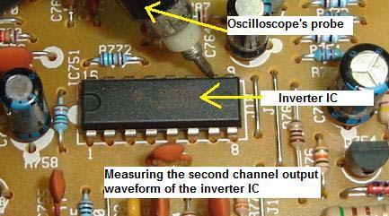

132 132


133 You can perform this kind of test on any inverter IC s but first you must get the IC data from the internet to find out which is the output pin before you do the measurement. Be careful not to short the scope probe on other pins otherwise you may end up killing the Inverter IC. If you get a good waveform then you have to perform the last test which is the frequency test. Frequency Test By placing the scope probe on top of the high voltage transformer you could see a sine waveform at your oscilloscope. The scope could pick up the frequency and this shows that the transformer is working. If the inverter board is not working due to faults in inverter IC, circuit, shutdown or etc your oscilloscope will only show a straight line. With all these waveforms test that I have clearly explained to you I believe troubleshooting LCD Monitors will be much easier for you 133
, missing one of the primary colour (either red, green or blue), lots of")

134 Color Problems In LCD Monitor Among all the problems in LCD Monitors, colour problems are the hardest to diagnose. There are many types of colour problems found in LCD Monitor such as rainbow colour (colour patches all over the screen), missing one of the primary colour (either red, green or blue), lots of vertical colour lines across the screen, wash out colour, lots of horizontal colour lines across the screen, distorted colour and etc. From experienced, colour problems usually indicates that the power supply, inverter board and the backlights are working fine and the real cause is in the Main board, loosen cable (wire or flex cable) and controller board (LCD panel) problem. Diagnosing cable is not a problem as you can reseat the cable or even use a multimeter set to continuity range to test the connection between the two points of the Main board and the Controller board. 134
 from the Scalar IC to the Controller IC in")


135 A faulty Scalar IC many times still could generate a good waveform measured by your oscilloscope but the waveform is not necessary carrying the entire data (information) from the Scalar IC to the Controller IC in the controller board. Even missing few of the bits during the data transfer, the display could produced display colour problems as mentioned above. Likewise even if the Controller IC is receiving the full data from Scalar IC, if the controller IC itself have problem it won t send the necessary signal or it send a distorted signal to the LCD driver IC in the tape carrier package (TCP) thus causing colour problems in the display. 135

136 After done many research there is still no proven way that one can accurately measure all the information in the data. Digital signal is totally different from when you are using oscilloscope to measure RGB signal in CRT Monitor. In the LCD Monitor, a single wire that connects between the Main Board and the Controller Board could carry lots of signals (information) and it is difficult to measure them. In order to repair the colour problems, one has to compare with a known good Main board or LCD panel. Either the Main board or the Controller board (LCD panel) could cause colour problems (assuming the cables is tested good). This way you can really save your time but the question is how are we going to get the same model of LCD Monitor for comparison? Assuming if you can t find the same LCD Monitor to compare and you have confirmed that the cable (wire or the flex cable) is in working condition then I guess there is no point of fixing them because the Main board and the LCD panel is very expensive and usually customers opt not to repair it and they rather prefer to get a new unit. Even if you have the same board and LCD panel for comparison, chances is still high your customers would not repair it due to the high cost. But you can do it to get some experience about LCD Monitor repair. If there is a LCD Monitor with colour problems and I have confirmed that the cable (between the Main board and the Controller board) and all the main voltages are good (2.5 V, 3.3 V, 5 V and 12 V) I would then try to reflow the Scalar IC and the Controller IC with a rework station (just in case if there are any dry joints). I would also scan all the SMD capacitors for short circuit surrounding the Scalar IC, MCU and the Controller IC. Sometimes the data in MCU can be lost and you need a programmer to reprogram it. If all have been done and the colour problems still exist, I would tell the customer it is either the Main board or the LCD panel were at fault and expect to pay higher fees in order to replace the parts. 136


137 How To Secured the Connector with Cloth Tape 137


138 White Display Problem in LCD Monitor If you see a white display in LCD Monitor this proved that the power supply, inverter board and the backlight is working fine and you need to troubleshoot other areas to locate the fault that caused white display problem. There are few reasons why a LCD Monitor can have white display problem: 1. Loose connection between the cable of the Main board and the Controller board. If the cable came out the Main board can t send the signal to the controller IC thus you get white display. In some LCD Monitor, it wills shutdown if no signal flows to the controller board. In order to solve the problem, try reseating the cable and retest the Monitor. 138


139 2. Bad Main board- Yes a faulty Main board itself can t send signals to the Controller IC. A defective voltage regulator, Scalar IC, MPU, EEprom and shorted surrounding SMD components could cause white display problem. Make sure there is signals flowing to the Controller board before you confirm is the Main board problem. You can test it by using Oscilloscope on the points at the connector either in the Main board or the Controller board side. 139


140 3. Bad SMD fuse in the controller board. There is a small SMD fuse located in the VCC supply line to the controller board. If this fuse open circuit then there would be no supply voltage going into the controller IC. Even though the controller IC is receiving the signals from the Main board but there are no signal outputs flowing to the LCD driver IC s located on the Tape Carrier Package (TCP) thus no image produced and only white screen produced by the backlights. Simply use a meter to test the SMD fuse to see if it for open circuit or not but before you do this make sure you have discharge yourself from static charge first by using a wrist strap. Components in the Controller board are very sensitive to static charge. Please take note on this. If the fuse tested good and there is signal flowing to the Controller IC, the only way to solve it is to replace the panel. 4. If you read the first sentence I mentioned that it is not a power supply problem but there was one LCD Monitor that intermittently produced white screen and it was caused by faulty electrolytic capacitors. When I check the ESR of the capacitors the ohms reading were very high. Replacing the faulty e-caps solved the intermittent display white problem. In future if you see a LCD Monitor with white screen problem please check on the secondary electrolytic capacitors first before you move on to test on other circuits that I have listed out in number 1, 2 and 3 above. 140


141 Vertical Line Across The Screen in Philip C LCD Monitor The complaint was one vertical line across the left screen of Philip LCD Monitor. First I did not know it was intermittent until I pressed on the top screen location where the vertical line was located. The moment I pressed the screen the vertical line goes off and the display was back to normal. When I released my hand the vertical line came back. Normally a one vertical line problem is hard to repair and most of the time it was the LCD panel fault (bad LCD driver IC, TCP package torn and controller IC). 141

142 After the controller board aluminium casing was removed, I search for the Tape Carrier Package (TCP) that located right to the vertical line with the help of the white tape. Please make sure you discharge all the static from your body by using a wrist strap before opening the controller cover as the components in the controller board are extra sensitive. When I pressed on the suspected TCP I found that the vertical line gone so it is confirmed that it was dry contact problem (connection problem) between the TCP and the controller board. There is no way we can solder the board as the soldering gun will immediately melts the TCP. The bond was done in factory and the factories have a special type of equipment to do the bonding job. 142


 between the TCP and the controller board as shown in the")
143 Since I could not do any soldering on the TCP I decided to use the pressure method. Now get a good quality rubber where the elasticity will last for many years. One way to get the rubber is to get it from the CRT picture tube. Those rubbers located at the side of the CRT yoke coils and you could easily see one the moment you open up a CRT Monitor cover. Cut some of the rubber and place it on the joint (bonding) between the TCP and the controller board as shown in the picture. Just place the rubber on top of it and gently cover back the controller board with the aluminium casing. The cover will put some pressure on it and press against the contact between the TCP and the controller board. 143


144 After everything was done, I let it run for many days and it worked perfectly okay and even until today there was no similar complaint from the customer. You can apply this tip too on problem with one horizontal line across screen. 144

.")
145 One Horizontal Line Across LCD Monitor Screen There could be three possibilities why one horizontal line across screen can happen in LCD Monitor. First it could be a missing signal from the Controller IC to LCD driver IC, second it could be the LCD driver IC itself defective and third it might be a dry contact in the tape carrier package (TCP). If you have read the previous chapter of how I solved the one vertical line problem across screen, you will get some idea how to diagnose the problem. 145

146 If the problem still the same (even if you have press the TCP contact point) then chances is very high it could be the LCD screen problem. There is no way you can repair this type of problem because you cannot get parts for the LCD driver and the Controller IC. Even if you can find the LCD driver IC there is no way you can do the soldering work as the solder gun can melt the TCP. The best way is still replace with a new LCD screen or panel if there is no dry contact problem in the TCP. 146


147 How to Repair LCD Monitor Power Adapter Repairing LCD monitor power supply pack is easier than the CRT monitor power supply. It is small and compact and usually has only one output which is 12 volt and ranges from 2 ampere to over 4 ampere. Some designed have 18 and 24 volts also. Nowadays most LCD power supplies are build into the main board such as the Dell E151FP LCD Monitor while the older type were separated as power pack module. The power pack module type is easy to diagnose because you can replace another working unit just to make sure is the power pack that giving problem. You may also use an external dc power supply to power up the LCD to confirm if the power pack is faulty or not. If you do not have the external dc power supply, you can always use this method to isolate the problem especially the symptoms are no power, low power and power blink. Using the rear light bulb (24 Volts) from a car and connect it to the power pack output jack. If it light brightly (not even a flick) then the power pack is okay. If it blink or dim the power pack have problem. Why have to use this method (light bulb) to test it? If there are components shorted or leaky at the LCD Monitor Main board, it will 147
 in the")
148 affect the power supply performance as well. From experienced, most of the LCD power supply problems whether in the power pack or built into Main board type were due to the failure of electrolytic capacitors (most probably due to heat) in the primary and secondary section. Most of the capacitors have a high ESR which causes the power supply to produce low output, blink or no power at all. Typical value electrolytic capacitors in the primary side are 47 and 100 micro farad 50 Volt and the secondary sides are 1000 to 2200 micro farad 25 volt. Sometimes you can see the capacitor top casing became bulged and the sleeve that covered the capacitor casing turned into darker colour like brownish. The power section in some of the LCD Monitors is still using the UC3842 pulse width modulation (PWM) IC. This type of IC is quite easy to find in the market compare to some power IC which is very difficult to get. Samsung 153V LCD monitor is using the TOP247F power IC which is quite easy to troubleshoot if power failed in this model. 148
149 Testing the power pack to see if the output is good or not If you suspect the primary power side having problem, what you could do is check all the components in it. If you are good in testing electronic components, you will only takes about 15 to 20 minutes to complete the job. If you are not sure how to test electronic components, then I strongly recommend you to visit to learn how to test electronic components like a professional. For more information on how to repair the power supply problem please go to the chapters of How to Repair No Power Problem in Dell E151FP and Samsung 510N LCD Monitor. Some power pack came in with only minor burnt and after cleaning it and replaced the fuse; it will work as good as a new one. Troubleshooting LCD power supply is not that difficult provided if you know how to test electronic components and how a power supply work. 149


150 Case Study- How to Repair Sharp LCD LL-T15G2 Power Adapter. The customer complaint of this Sharp LCD LL-T15G2 LCD Monitor was no power in the power adapter and LCD screen. The moment I opened up the casing I saw the internal cover and the power supply board had burnt mark on it. First I thought it was hit by lightning but upon carefully inspect the board I found that the yellow wire was touching one of the bridge rectifier diodes pin. You could also clearly see that one part of the track had broken. Surprisingly the fuse didn t open circuit! The darken board have to be clean with Thinner solution before I begin starting to check on the suspected components. First make sure the filter capacitor have no voltage checked with the help of your voltmeter, if 150
151 there is voltage you can discharge it with a 2.2 k ohm 10 watt resistor place across the capacitor leads. This is just a normal procedure as I don t want any of my readers who are new in this field to get discharge through his body from the capacitor charge. Once I have confirmed that there are no more voltage in the filter capacitor, I will then use my analogue meter set to x1 ohms to test on the power FET (part number is 2sk3114). Place the black probe to the centre pin of power FET and the red probe to the other two pins one at a time. The meter should not register any reading, if there are readings; it could be the power FET has shorted. In order to confirm it the best way is to remove the FET from circuit and check it. If the power FET didn't blow, chances is very high the pulse width modulation IC (PWM) KA3842B is good. The resistors in the primary side checked to be okay too. 151


152 After this test I will use the Dick Smith flyback tester to place across the power transformer primary winding to see if the winding is shorted or not. The readout was 8 full bars and this proves that not only the primary winding is okay, the secondary diodes as well. With this meter, I can say that it truly save my troubleshooting time. If either the primary winding or the secondary diode shorted, the meter readout would drop to very low or totally goes off. 152


153 Now, I would just scan all the electrolytic capacitors with my ESR meter although I knew that the chances for the capacitors to go bad is very slim due to the problem was short circuit between the yellow wire and one of the bridge diodes and it definitely would not affect the capacitors. Okay coming back to the bridge diodes, one can always check the diodes while it still on boards with your analogue meter set to x1 ohm. It should not register two similar readings. If you are not sure about the reading you can always compare with the other diodes. Checking the diodes on board I found one to be defective and I removed all of them and replaced with 4 new 1N4007 diodes. For your information, if one of the diodes shorted or opens circuit, one has to replace the other 3 diodes as well. I do not know about you, but from my years of electronic repair experienced, I do came across problem where after sending back the equipment (after replacing one of the bridge diodes), few days or weeks later the same customer came back with the same problem i.e.; no power 153


154 (caused by another shorted diode in the bridge circuit). For reliability reason and to prevent the customer from sending back the equipment for warranty claim, the best is to replace all of them if found one diode to be faulty. This diode is not expensive compare to the time loss and it may affect your reputation too as an electronic repairer. After the replacement of the new diodes, you need to join back the broken track with the help of a lead cut from a 2 watt resistor. Before you switch on the power supply, one must always connect a 100 watt light bulb to test. The reason for using the light bulb is to prevent the power supply components that you have just replaced to blow again just in case if there is short circuit somewhere in the power supply that you have missed to check. 154


155 Simply remove the fuse and connect the two wires of the light bulb across it. Now switch on the power supply and observe the light bulb. If the bulb lit brightly and stays there for a long time, this means that there are still problems in the power supply. If the bulb didn t lit, you can now put your probe at the output to check for the presence of 12 volt. Once you get the output, you can put back the fuse and close back the cover. When I plug the 12 volt jack to the LCD Monitor, there was no power. I presumed the short circuit in the power pack/adapter may have caused the LCD internal fuse to blow as well. True enough, after opening up the LCD cover and check on the fuse, it found to be open circuit. Solving the internal fuse and the power supply problem put the Sharp LCD Monitor back to life again. Not only you gained the satisfaction from repairing the power supply, you get paid also from your customers too! That s all for it, take care my friend. 155
 burnt at the side and you could still recognized the resistor colour code. The current sense resistor (0.")
156 How to Repair DELL E151FP LCD Monitor with No Power Symptom The DELL E151FP LCD Monitor came in with no power symptom and upon opening up the cover I saw few components that were burnt. R623 (4.7 ohm) burnt at the side and you could still recognized the resistor colour code. The current sense resistor (0.68 ohm) outer layer partly had came off and slightly burnt and the filter capacitor C605 (68uf 400v) one of the pins had became rusted and came off when I tried to desolder the pin. This is not a new model and I believe lots of experienced techs had solved the problem. But for those who haven t come across this problem, you may use the procedure to troubleshoot and repair any other type of LCD Monitor with power problem. 156

157 I will first remove the power transformer and make sure it rings okay with dick smith flyback tester. I do this first because I don t want to waste my time checking other components and later only found out that the power transformer is the caused of the power problem. Once it rings okay I will measure all the secondary diode. For your information most LCD Monitor power supply widely used the dual schottky type diodes and the specification usually in the 10 to 20 amp with about 40 volts. However I do come across some designed are still uses the ultra fast recovery type diodes in the secondary section. Make sure you know how to check a normal diode and a schottky diode. Refer back to Schottky diode testing methods in my previous chapter. I will then check for the ESR of electrolytic capacitors too. Once I confirmed that the secondary side components are all tested okay, I would then proceed to remove all the components in the primary side. Some components in the primary side you can check on board like the bridge rectifier and fuse. If you are new in LCD Monitor repair I would suggest you to check all components off board (with a lead removed from board). With this way you will be sure that all components that you have scanned through are okay. 157


158 These are the components that I found defective; fuse-2a, R ohm, R613-1K, R ohm, R ohm, D604-1N4148, Q601- SSS6N60A, C605-68UF 400V and IC601-UC3842B. Total was nine components and it took me less than 20 minutes to check all the components in primary side. Now is the time to search for spare parts. After spending about 5 minutes in the spare part compartment I managed to find all components except the power FET SSS6N60A. Though this part number is mostly used in switch mode power supply, my electronic supplier does not have this in stock. I would then browse 158

159 through the semiconductor data book to search for equivalent part number. From the book, it suggests to use the K1118 as replacement. After all the new components have put into their original place or location and of course with the power transformer soldered, I don t immediately switch on the power supply. I would first use a 100watt light bulb connected in series with the live line. The best place to put the light bulb is the fuse holder area. Remove one of the fuse lead and connect the light bulb across it. Power it on and begin to observe the bulb. If it brightly lit and stays that way for couples of minutes then there is still problem in the power supply. However, if the bulb doesn t light at all then this is a good sign that the power supply may be working. Use a multimeter (analogue or digital meter) to place the red probe at the centre pin of the Schottky diode (and black probe to cold ground) and switch On the power. If you get some accurate voltage reading from the outputs and the bulb doesn t light at all, then this confirmed that the power supply is working. Switch off the power supply and connect back the fuse and turn the LCD Monitor On again. I m very sure the LCD Monitor will now work. 159
 then you")

160 Assuming the output Schottky diodes are stand alone type (normal ultra fast recovery diode) then you need to place your red probe to the cathode and black probe to cold ground as shown in the below photos: 160

161 The right way to connect the black probe to cold ground Monitor finally come back to life after the replacement of parts Whether you are troubleshooting the DELL E151FP LCD Monitor or other brands, you can always use the procedure given above to repair the power supply problem. This method can be even use to repair other types of power supply too. No matter what types of power supply you are troubleshooting, just make sure you know how to check and test the basic electronic components. If you ever missed one, sad to say you would not be able to solve the problem or it might just take you many of your precious hours to complete the job. Happy hunting! Visit the website TestingElectronicComponents.com and learn how you can become a professional in testing electronic components. 161

162 How to Repair Dell E152Fpb LCD Monitor with No Display Symptom The complaint for this DELL E152Fpb LCD Monitor was when switched ON has power (LED lit) but no display. LCD Monitor is different from the CRT Monitor where you could feel the static at the front of the picture tube or hear the rushing sound from the high voltage produced by the flyback transformer. In LCD, if no display you won t be able to know if the inverter board is working or not unless you use an oscilloscope to point near the inverter board and the scope could display a waveform indicating the inverter board is functioning. A faulty Main board may cause no display problem in LCD Monitor. If there is a problem in the Main board, it would not send an On (enable) signal to the soft start circuit and no voltage will flow to the supply pin of inverter IC thus no waveform produced by the output of high voltage transformer. 162
 IC-some preferred to call it as inverter IC.")

163 In the above case, after the cover was removed, the first thing I check was the VCC (supply voltage) to the inverter IC. This model is using the famous TL1451ACN Pulse width modulation (PWM) IC-some preferred to call it as inverter IC. Pin 9 is the VCC supply input and it should have about 12 to 14 Volts when the power is On. Measuring the pin with my faithful digital multimeter, it reads only about 3 volts which indicates there s a problem in the supply line. It could be components that are faulty that dragged down the line or it could be the switch mode power supply itself that don t produce enough power. In order to find the answer as which section is giving problem, the first clue was that the power LED indicator lit and this prove that the IC is supplying enough power to the circuit. Another clue was that the meter is registering about 16 volts at the input of the 2A Pico fuse. Because of these clear answers, we can conclude that the switch mode power supply is working fine. You can also use a 24 volt light bulb to confirm it. You may have already read my other LCD Monitor repair chapter which talks about using 24 volt light bulb for troubleshooting purposes. I kept on asking myself, why the voltage drop to 3 volts after the fuse. Before the fuse it reads about 16 volt but after the fuse it reads only 3 volts! I didn t suspect the fuse, because the fuse can only either yes or no 163

 I direct replaced, afraid they would breakdown when under load. The only component that I didn t check was the fuse!")
164 and no in between. The first circuit that I checked was the start circuit but all components checked to be okay. I even desoldered the pin 9 of TL1451ACN inverter IC just to make sure it is not this IC that pulled down the voltage. This problem really challenges my troubleshooting and repairing skill, because almost all suspected components already checked to be working. Even the start circuit transistors (C945 & A733) I direct replaced, afraid they would breakdown when under load. The only component that I didn t check was the fuse! By using my meter placed across the fuse, instead of getting low ohms or zero ohm reading I got Kilo ohms! I ve got a surprised and don t believe that a fuse can actually go into high ohms instead of open circuit. I always thought that a fuse is either close or open circuit. 164
165 A fuse with low or zero ohms turned into high ohm thus the 16 volts dropped to 3 volts! I ve came across lots of this type of Pico fuse but this is the first time a fuse changed into high resistance. Replacing only the fuse put the DELL E152Fpb LCD Monitor back to life. The lesson learned from here is that don t assume that a component is always in a good working condition. You have to confirm it with your meter and if you still suspect the component is giving problem, simply replace it with a known good one and retest the equipment. For your information, electronic components can breakdown when under full operating voltage. 165


166 How to Repair Dell E153Fpc LCD Monitor with Display Shutdown Problem Repairing the DELL E153Fpc LCD Monitor with the complaint of display shutdown after few seconds (power LED still on) was not difficult. Normally when this type of problem happens, we would first suspect the inverter board, then the filter capacitors and lastly the main board. A defective in one of the lamps and a faulty TL1451AC PWM IC or inverter IC may cause the display to shutdown as well. If the lamp is defective, it will send a feedback to pin 3 or 14 of TL1451AC IC and caused it to stop producing output signal thus the display just shut off once you switch it On. The power board is using a SG6841D PWM IC and a FQPF7N80 power FET. If this power section blow, it is quite easy to troubleshoot because it 166


167 has fewer components. You can also use other part numbers to substitute the power FET like the K1118. As usual, after opening up the cover, I would first check for any burnt components, loose connector, cracked board, dry joints and etc before doing the voltage test. As for the lamps, I would check it last because lamps were seldom spoilt. Upon scanning for any bad components before starting the voltage test, I found a filter capacitor that had turned into darker colour. Using the ESR meter revealed the ESR ohm has shoot up to 12 ohms. This filter capacitor located at C922 with the value of 1000 micro farad 16 volt. If you don t have the ESR meter you can always use the digital capacitance meter. The value that I got from measuring the bad capacitor was 57 microfarad. If you don t have ESR meter, make sure you get oneit s fast and accurate. Now, the question is why a filter capacitor can cause the display to shutdown? If you carefully see the picture, I ve drawn the yellow path to show you how the voltage is flowing. By the way, the voltage at the bad filter capacitor line is 12 volt. The voltage passed through a SMD transistor in the start circuit and flow straight to pin 9 (VCC) of TL1451AC IC. In order to let the 12 volt to 167
, both transistors in the Start Circuit can t be turned on and no voltage will follow through the IC.")
168 flow through the transistor and reach the VCC pin of the IC, first, an ON signal must be sent from the main board to trigger the transistor. If no signal send to the transistors (off signal), both transistors in the Start Circuit can t be turned on and no voltage will follow through the IC. Thus if the Main board or any of the Start Circuit components spoilt, there will be power but no display because the TL1451AC would not send signal to the Royer type L, C resonant and boost circuit (that consists of C5706 transistors, capacitor, transformer, coil, FET, diode and resistors) so no high voltage produced by the high voltage transformer and this will lead to no display. In the above case, the LCD Monitor display shutdown was due to the ripple because of the bad filter capacitor. The ripple caused the TL1451AC IC to be unstable and eventually shutdown the output signal. Replacing only the filter capacitor solved the DELL E153Fpc LCD Monitor shutdown problem. 168

169 Conclusion, don t always presumed that LCD Monitor is very tough or difficult to repair. From the above article, you could see that the caused of the shutdown problem was only a bad capacitor. If you fully understood how LCD Monitor works, then chances for you to successfully repair the monitor is very high but again it depends on the availability of spare parts. If you ever come across any LCD Monitor sent to you for repair for the first time, go ahead and start troubleshoot it. Who knows one day LCD Monitor repair could become one of the major source of income to you and your business. 169

170 How to Repair Power Blink in Dell E173fpb LCD Monitor Troubleshooting DELL E173FPB LCD Monitor with power blink symptom is quite easy if you know the right procedure to test it. There are two sections in the monitor that can cause power to blink. It is either primary or secondary section or even sometimes both sections can be faulty. So to isolate as which section is giving problem. I used an automobile 24 Volt light bulb (brake light) and connect it between the 12 volt supply line and cold ground with the Pico fuse (along the 12 Volts line) removed. If the bulb still blink chances is very high the power primary section have problem. Do not overlook the other voltages line as well such as the 3.3 and 5 volts. If any components shorted that gets the supply from the 5 and 3.3 volts, the power also may blink. If the 24 Volts bulb lights up we can assumed that the power supply is working fine and something shorted further down the line that makes the power supply to blink. If the bulb lights and you continue to check the power section, it will be going to waste your time. You should now concentrate on the secondary section circuit such as the four transistors C5707 that drive the high voltage transformer in the inverter board. 170


171 Just think these transistors like the horizontal output transistor (HOT) in the CRT monitor that drive the flyback transformer where it worked so hard and chances for it to breakdown is very high. Checking the four transistors off board found one of them has a shorted reading with an ohmmeter. This transistor can get faulty by itself or it could be some others components that caused it to develop a short circuit such as a defective high voltage transformer but all of the four high voltage transformers checked to be okay with ringer and ohmmeter test. 171

172 Now, here is the secret that I m going to reveal to you. If you just replace the defective transistor only, chances is very high the transistor or another C5707 transistor will breakdown again. Usually what a technician does is to test the other transistors with either an analogue or digital meter. If you use both meters to test the transistors then you have missed out on the faulty transistor because both meters won t reveal to you the hfe reading of the transistors. Only some digital meters have the hfe checking feature. In other words, you have to test the hfe reading of a transistor. Although you can replace the other three transistors directly, why not we do some detective work to find the cause of the problem? 172


173 Using the Peak electronic atlas component analyzer, I could clearly see the different between a good and a bad transistor. A good C5707 transistor has hfe reading from 320 to about 390 but the bad one reads 467! The other two C5707 transistors have reading about 350. In the above case only two C5707 transistors were replaced and you save the other two. I have burned in test this LCD monitor for many days and it worked perfectly fine. Conclusion- Whether you repair the DELL E173FPB LCD Monitor or any other model such as the E172FPB or E171FPB, basically the testing method is the same. You could also use this testing procedure on other brand of LCD Monitor too. Please check also to see if there are any dry joints (solder) in the surrounding circuit like the legs of the high voltage transformer. A Peak Electronic Atlas Component Analyser 173


174 How to Repair Intermittent No Power in Acer AL511 The complaint for the ACER AL511 LCD Monitor was intermittent no power. That s mean when the front power button was pressed the power would sometime comes and sometime no response at all. When there is power the display would appear and it worked perfectly fine until when you switch the power off and then switch it on again. Most of the time it will work but sometimes the power LED just doesn t light. My first impression was the defective power push button micro switch. 174


175 If the intermittent no power problem happens in the CRT Monitor, then most probably it is the start up circuit resistors fault. The start up resistors value may have gone too high causing it to have intermittent no power symptom. It could also be a defective on/off power switch too. Let s get back to this ACER AL511 LCD Monitor problem. The reason I don t suspect start up resistors fault in this ACER AL511 LCD Monitor was because the power on/off switch signal was derived from the CPU. Unless you talk about LCD Monitor that used mechanical on/off switch where it have the same function as the CRT type of Monitors. Opening up the cover was very easy and you can clearly see the three boards i.e. the main board, power/inverter board and the control panel board. The LCD controller board was located at the back and beneath the metal casing. Using my analogue meter set to X 1 ohm to check on the micro switches at the control panel board found two of them to have intermittent problem. Sometimes the meter s pointer would kick when the button was pressed and sometimes it won t. 175


176 Next is to solder out the faulty micro switches and replaced them with a known good one. After the soldering job was done, I checked on the power/inverter board just in case if there are any dry joints that need fresh solder. Well, it seems that only the micro switches have problem and now the power button was pressed and the display immediately appeared. I deliberately pressed many times the power button just to check if the intermittent problem had been solved. Yes, the display and power comes whenever the button was pressed. In the above case, it proved that LCD Monitor problem can be caused by a minor fault and it is not necessary must be a major problem. 176


177 How to Repair No Display Problem in Acer FP558 LCD Monitor This Monitor that belongs to my company just out of sudden became no display and with amber LED light On. Since the power LED already lit, I presumed the output voltages from the power supply should be working fine. If you are unsure about the output voltages, you can always measure it again with a digital multimeter. Main board need few voltages to run (2.5V, 3.3V and 5 Volts). However some older LCD Monitors may only use the 3.3V and 5 Volts. 177


178 Placing my red probe to the VCC supply pin of EEprom and my black probe to cold ground, the digital meter read 5 Volts which indicates there was supply going in into the Main board. Next I use an oscilloscope to check on the crystal waveform. In order for the MCU to work correctly, the crystal oscillator must have a waveform. Without waveform, this indicates either the crystal, surrounding crystal components or MCU have problem. True enough when my oscilloscope probe placed on the pin of the crystal, there was no waveform and showing only one straight line which was abnormal. Since I have a similar working LCD Monitor with me and the MCU was located in an IC socket, I decided to replace the MCU first before changing the crystal. 178

179 The moment after I replaced with a working MCU and power ON, the display immediately appeared and the power LED light turned green! I use my scope to check on the crystal and yes there was a waveform. From the above test, it was very clear that the MCU is the culprit. Unfortunately there is no way for me to get the original MCU and I kept the Monitor as spare parts for future use. 179

180 From above I believe you have some ideas how to troubleshoot and repair any LCD Monitor with no display and the power LED turned amber colour. Sometimes it may not be the MCU fault, it could be a defective crystal or even shorted components in the crystal circuit area. If you do not have an oscilloscope make sure you get one for easy troubleshooting. 180


181 How to Repair Samsung 151V With Black and White Horizontal Bar Across Screen This Monitor has the complaint of many black and white many horizontal white bars across screen. Because there was display we can conclude that the power supply, inverter board and the backlights were working fine. The suspected bad parts could be either the Main board or the LCD panel. 181

182 In order to find out which parts is the cause of the problem, I first check the output signals from the Main board to the LCD panel. Using oscilloscope you could clearly see if there are any waveform signals flowing from the Main board to the controller board in LCD panel. By placing the black probe of oscilloscope to cold ground and the main probe to the connector of the Main board, I could see lots of signal activities and this shows that there were signals flowing in into the controller board in LCD panel. Because there were signals flowing in into the LCD panel, chances that the LCD panel have problem was very high. 182


183 I have a working same model of LCD Monitor in my store room so I took the LCD panel out and fixed it on the bad LCD Monitor. Guess what? A nice display came out and this 100% confirmed that the horizontal black and white bar problem was caused by a defective LCD panel. In LCD Monitor repair, we sometimes have to keep some working LCD Monitors for comparison. The parts in the controller board were just too small and very sensitive to static charge. Even though you have confirmed that the controller IC is the cause of the problem, there is no way you could ordered one. The best is still directly replacing the LCD panel. 183

184 How to Repair Samsung 153V LCD Monitor With Dim Display Problem One of the common problems in Samsung 153v LCD Monitor was display dim. If you get closer to the screen and begin to observe the display under dark environment you actually could see the display but it was very dim. If you press the front panel button, the On Screen Display (OSD) would appeared and this proved that the Main board and LCD panel is working and the problem is in the inverter board. You may also use a torch light to shine on the LCD panel to see if it is dim display or no display at all. The function of inverter board is to generate an ac wave from dc voltage to power up the lamps which was located at the top and bottom of the LCD Monitor. If the inverter board has problems it would not light up the lamps and what you could see only a dim display. I still could recall when I first encountered such problems long time ago and because of lack of information, I could not solve it. I did call up my repair friends to asked about the solution but no one able to give me an answer. Due to this I have to do my own research to find the answer and I ve never give up. Winston Churchill once said Never, never, never give up. 184

185 Let s start now! Once the cover and the internal aluminium casing were opened I saw two bulged filter capacitors at the secondary side of switch mode power supply. The value was 470 and 1000 microfarad 25 volts. I saw four more electrolytic capacitors located at the inverter board have changed colour and the value was 47 micro farad 25 volts. Browsing through the whole board with my ESR meter I found another capacitor faulty (220 uf 25 volts) which was near the fuse (3amp). Since this capacitor was located at the same line with the fuse, I presumed that the fuse may give way as well. True enough, checking the fuse with an ohmmeter revealed that it has open circuit. 185


186 Now, the real problem faced by many electronic repairers who deals with this model was, after replacing all of the components above the LCD Monitor still would not work-it s still dim! First you have to ask yourself why the fuse blown? Could it be caused by the defective capacitors or something shorted beyond the fuse line? The nearest circuit to the fuse was the start circuit that consisted of a pair of NPN and PNP digital transistor (4k7 +4k7 resistor built into the transistor). Some other LCD monitor designed used the combination of C945 and A733 in start circuit. 186
 that caused the fuse to blow but in the above case both digital transistors are tested okay.")
187 By the way the part number for Samsung 153V start circuit transistors were the A6J (PNP digital transistor) and the A8J (NPN digital transistor) as shown in the picture. Sometimes only these transistors have problems (shorted) that caused the fuse to blow but in the above case both digital transistors are tested okay. Since both transistors were working, now the concentration have to be in the four IC s that drive the high voltage transformers because the 12 volts voltage was supplying to each of these IC s. These 4 IC s have many part numbers and the most common one that the manufacturer used was 4532m. Some board used the AD4E10 and BBD3N13 part number. At the moment it is quite hard to get the datasheet or technical specification for this number even from the internet. 187

, pin 4 (gate) and pin 5 & 6 (drain and both pins joint internally). From the above test I found two of these IC s have shorted.")
188 Do you know what is inside these IC s? It is actually a pair of P-channel and an N-channel Mosfet built into it. And do you know that it can be test with a meter? Yes, if you use the Peak atlas component analyzer, it would prompt to you the result. From the result what I got were N channel FET located at pin 1 (source), pin 2 (gate), pin 7 & 8 (drain and both pins joint together internally). As for P channel FET, pin 3 (source), pin 4 (gate) and pin 5 & 6 (drain and both pins joint internally). From the above test I found two of these IC s have shorted. Replacing these two shorted IC with the capacitors and fuse put the LCD Monitor back to life! One more thing I would like to share on this model was that the inverter PWM IC BIT1305 was quite robust and rarely gave problem. 188

189 How to Repair No Power Problem in Samsung 153V LCD Monitor Repairing Samsung 153V LCD power supply is just like troubleshooting those CRT type. This monitor came in with no power symptom. If you are first time repairing this type of power supply, I recommend you to first remove the switch mode power transformer. Then check every single component in the primary section, before you continue to check the secondary section. You have to be good in testing basic electronic components in order to detect the fault. You can always visit my other website TestingElectronicComponents.com just in case you do not know how to test basic electronic components. If you do not know the right way to test, you might miss out a bad component and this will lead you not able to solve the problem. After carefully inspect all the components in the power supply section, I found the filter capacitor do not have any reading using digital capacitance meter (open), the two round type fuse also open circuit, 1N4744 (15 Volt zener diode) short circuit and lastly the power IC TOP247F blown! Testing the switch mode power supply primary winding with a dick smith flyback tester shown green LED bar which indicates good winding. 189
. Now we have confirmed that only five components found to be faulty.")

190 What we left here were the secondary diode and filter capacitor. Upon checking them with analogue meter and ESR meter, I found all of them to be good condition. Other area like Main board and inverter board also looks okay (Power failure rarely affect these two circuit). Now we have confirmed that only five components found to be faulty. One by one the components were replaced and just before you switch on the power supply, make sure you connect a 100 watt light bulb in series with the live ac line (remove one of the round type fuse). Once it is done you can then proceed to switch on the LCD monitor to look at the brightness of the bulb. If the bulb is very bright and didn t go off even On for couples of minutes, this suggests that there is still short circuit somewhere in the power section. If it dim or totally goes off, you can now place your red probe to the secondary side to check if any DC voltages present at their respective line. If there are DC voltages present at the output, you can switch off the power, discharge the filter capacitor (for safety purposes), remove the light bulb and connect back the new fuse to its original location. 190


191 You are now hundred percent sure that the LCD power supply won t blow once you switch it On. By the way the filter capacitor is rated at 105 Celsius and you cannot replace it with the 85 Celsius type otherwise it may open up again after using for couple of weeks or months. The ventilation in LCD monitor is not as good as the CRT Monitor, because the power supply is fully covered by a large aluminium plate and it can get hot pretty fast. After installing the fuse and power On the Monitor, it worked perfectly fine! Conclusion, whether you are troubleshooting Samsung 153V LCD power supply or other brand of LCD monitor, the procedure is the same. Who knows the power problem in this LCD Monitor is a common fault and in the future you can tackle this brand of power supply problem in the shortest time. To check electronic components is not that difficult, but to get the original parts like the power IC will consumed you lots of time. 191


192 How to Repair No Power Problem in Samsung 510BN LCD Monitor The complaint for this Samsung 510BN LCD monitor was no power; after the cover was opened I found that the power filter capacitor still hold some charged and the voltage was quite high. A good monitor by right the filter capacitor stored voltage should be discharged in less than 10 seconds. This indicates that there was something not right in the circuit. If you happen to repair this type of power problem, make sure you discharge the filter capacitor first before checking on others components. 192

193 You can use a 2.2 K ohm 10 watt resistor to place across the filter capacitor to discharge the voltage. After the filter capacitor voltage already discharged, I use a dick smith flyback tester to measure across the primary winding of the switch mode power transformer to see if there are any short circuit occurred. The result of the test was the flyback tester LED light all goes off which means there must be components shorted either in the primary or secondary section, sometimes the primary winding can go shorted also. A shorted power IC (this monitor is using the 4 pins 5L0365R power IC) in the primary section or a shorted diode in the secondary section would pulled down the flyback tester LED bar to the lowest. If the flyback tester LED have 8 full bars, this means that the components such as power IC (power FET if have), power transformer primary winding and all the secondary diodes are not shorted. 193


194 To isolate if the shorts is either in the primary or secondary section, you must desolder the power transformer. Check the primary winding of the power transformer off board first before you test on all the secondary diodes using analogue meter set to times 10 K ohm. A shorted diode will show two reading registered at the analogue meter. In this Samsung 510bn LCD monitor power supply, the caused of the no power and filter capacitor take longer time to discharge was due to a 194
195 shorted secondary diode which was from the Schottky type with the part number of SB5H100. Searching the internet, I found this diode s technical datasheet; it is a 100Volt 5A Schottky diode. This shorted diode is located at the 12 volt rail which means it converts the ac to 12 Volt dc. After the diode replacement was done, the LCD monitor work perfectly fine! Whether you are troubleshooting the Samsung 510BN LCD Monitor power supply or any type of switch mode power supply, basically the procedure of testing it is the same. Of course there are many more methods to locate the shorted secondary diode such as directly test the diodes, but this method can check for components shorted even without using the soldering gun. This means, if the flyback tester shown 8 full bars, then don t waste your time to test on all the secondary diodes again. Get one dick smith flyback tester and you could see how valuable this meter is in performing variety test for you such as checking the computer monitor B+ coil, flyback transformer, CRTt horizontal yoke coil, ballast and many more. Download the schematic and build your own flyback tester at: 195
 and then for couples of seconds the power led light goes off.")

196 Repairing Samsung 713N LCD Monitor with OSD Problem. This Samsung 713N LCD monitor came in with no display symptom and no power. In other words, once you switched on you could see the power LED lights up (no display) and then for couples of seconds the power led light goes off. When I removed the signal cable and switched on, now I could see the check signal cable OSD appeared at the screen. This proved that the inverter board, lamp and power supply is working. Again, I plugged in the signal cable, the display and power LED light went off. After opened up the cover, I check the on/off signal from the Main board to the start circuit but no voltage flowing in it. By right it should have at least few volts to trigger the Start Circuit. With signal cable in, there was 196

197 no on/off signal to the start circuit but when the signal cable was disconnected, you could clearly see from your meter there is an on/off signal going into the start circuit thus the OSD display appeared with the word check signal cable. From this test, it is very obvious the Main board problem. To confirm whether the Main board have problem or not, you have to use a similar Samsung 713N model to confirm it. True enough, after substitution with a known good board, the monitor is okay. So now we can confirm is the Main board faulty. As mentioned in previous articles, to troubleshoot LCD monitor is easy but to get the part is a little bit difficult. Samsung don t sell you the Main board, if you send to them for repair, they will charge a very high price which is not worth to repair. Swapping the Microcontroller (MCU) with a known good one proved that the MCU is the caused of the no display and OSD running across the screen problem. In fact this problem is a common fault in many models of Samsung LCD Monitor. 197

 and once")
198 Recently I stumbled upon a Chinese forum while surfing the internet and found a picture of a programmer that can do the job of reprogramming the MCU in LCD Monitors. I did not order from them because I do not know how reliable about that company. I will continue to surf the internet and find the solution for this kind of problem (MCU lost data) and once I got it I will post into my blog. And here is the photo of the programmer. 198
These are used for producing a narrow and sharply focus beam of electrons.
 CATHOD RAY TUBE (CRT) A CRT is an electronic tube designed to display electrical data. The basic CRT consists of four major components. 1. Electron Gun 2. Focussing & Accelerating Anodes 3. Horizontal
Technology White Paper Plasma Displays. NEC Technologies Visual Systems Division
 Technology White Paper Plasma Displays NEC Technologies Visual Systems Division May 1998 1 What is a Color Plasma Display Panel? The term Plasma refers to a flat panel display technology that utilizes
Display Devices & its Interfacing
 Display Devices & its Interfacing 3 Display systems are available in various technologies such as i) Cathode ray tubes (CRTs), ii) Liquid crystal displays (LCDs), iii) Plasma displays, and iv) Light emitting
VIDEO 101 LCD MONITOR OVERVIEW
 VIDEO 101 LCD MONITOR OVERVIEW This provides an overview of the monitor nomenclature and specifications as they relate to TRU-Vu industrial monitors. This is an ever changing industry and as such all specifications
LA1500R USER S GUIDE.
 LA1500R USER S GUIDE www.planar.com The information contained in this document is subject to change without notice. This document contains proprietary information that is protected by copyright. All rights
Product General Specification
 . General Description The is a Color Active Matrix with an integral Cold Cathode Fluorescent Tube(CCFT) back light system. The matrix employs asi Thin Film Transistor as the active element. It is a transmissive
Liquid Crystal Displays
 Liquid Crystal Displays Cosmin Ioniţă - Spring 2006 - A brief history 1888 - Friedrich Reinitzer, an Austrian chemist working in the Institute of Plant Physiology at the University of Prague, discovered
16 Stage Bi-Directional LED Sequencer
 16 Stage Bi-Directional LED Sequencer The bi-directional sequencer uses a 4 bit binary up/down counter (CD4516) and two "1 of 8 line decoders" (74HC138 or 74HCT138) to generate the popular "Night Rider"
Simple Way To Brighten Up A 17 Computer Monitor Picture Tube
 Simple Way To Brighten Up A 17 Computer Monitor Picture Tube By Jestine Yong http://www.electronicrepairguide.com Give a copy to a friend This article is free. You can post this article to your website.
Application Note [AN-007] LCD Backlighting Technologies and Configurations
![Application Note [AN-007] LCD Backlighting Technologies and Configurations](/thumbs/81/83266365.jpg "Application Note [AN-007] LCD Backlighting Technologies and Configurations") Application Note [AN-007] LCD Backlighting Technologies Introduction Liquid Crystal Displays (LCDs) are not emissive i.e. they do not generate their own light. Transmissive and transflective displays require
Application Note [AN-007] LCD Backlighting Technologies Introduction Liquid Crystal Displays (LCDs) are not emissive i.e. they do not generate their own light. Transmissive and transflective displays require
2013, 2014 Hewlett-Packard Development Company, L.P.
 User Guide 2013, 2014 Hewlett-Packard Development Company, L.P. The only warranties for HP products and services are set forth in the express warranty statements accompanying such products and services.
Uni700 LCD Controller
 Landmark Technology Inc. Uni700 LCD Controller For TFT LCDs with Resolution up to 1,920 x 1,200 (Version A) January 27, 2009 1 1. Introduction The Uni700 controller board is designed for LCD panels of
High Performance TFT LCD Driver ICs for Large-Size Displays
 Name: Eugenie Ip Title: Technical Marketing Engineer Company: Solomon Systech Limited www.solomon-systech.com The TFT LCD market has rapidly evolved in the last decade, enabling the occurrence of large
15 Inch CGA EGA VGA to XGA LCD Wide Viewing Angle Panel ID# 833
 15 Inch CGA EGA VGA to XGA LCD Wide Viewing Angle Panel ID# 833 Operation Manual Introduction This monitor is an open frame LCD Panel monitor. It features the VESA plug & play system which allows the monitor
Liquid Crystal Display (LCD)
") Liquid Crystal Display (LCD) When coming into contact with grooved surface in a fixed direction, liquid crystal molecules line up parallelly along the grooves. When coming into contact with grooved surface
Liquid Crystal Display (LCD) When coming into contact with grooved surface in a fixed direction, liquid crystal molecules line up parallelly along the grooves. When coming into contact with grooved surface
USER MANUAL. 27 Full HD Widescreen LED Monitor L270E
 USER MANUAL 27 Full HD Widescreen LED Monitor L270E TABLE OF CONTENTS 1 Getting Started 2 Control Panel/ Back Panel 3 On Screen Display 4 Technical Specs 5 Care & Maintenance 6 Troubleshooting 7 Safety
Introduction...2. Features...2 Safety Precautions...2. Installation...4
 PE1900 Contents Introduction...2 Features...2 Safety Precautions...2 Installation...4 Unpacking the Display...4 Locations and Functions of Controls...4 Connections...5 Using Your Display...7 Turning the
High-resolution screens have become a mainstay on modern smartphones. Initial. Displays 3.1 LCD
 3 Displays Figure 3.1. The University of Texas at Austin s Stallion Tiled Display, made up of 75 Dell 3007WPF LCDs with a total resolution of 307 megapixels (38400 8000 pixels) High-resolution screens
ID C10C: Flat Panel Display Basics
 ID C10C: Flat Panel Display Basics Renesas Electronics America Inc. Robert Dunhouse, Display BU Engineering Manager 12 October 2010 Revision 1.1 Robert F. Dunhouse, Jr. Displays Applications Engineering
Flat Panel Displays: LCD Technologies and Trends
 Flat Panel Displays: LCD Technologies and Trends Robert Dunhouse, Sr. Engineering Manager, Display BU Class ID: 4C01B Renesas Electronics America Inc. Robert F. Dunhouse, Jr. Sr. Engineering Manager, Display
1 Your computer screen
 U.S.T.H.B / C.E.I.L Unit 7 Computer science L2 (S2) 1 Your computer screen Discuss the following questions. 1 What type of display do you have? 2 What size is the screen? 3 Can you watch TV on your PC
User Manual. PC / HD Scaler. with advanced video processing. VGA to Component Video Component Video to VGA VGA to VGA Component to Component
 User Manual PC / HD Scaler with advanced video processing VGA to Component Video Component Video to VGA VGA to VGA Component to Component Model 1366 WARNINGS Read these instructions before installing or
Types of CRT Display Devices. DVST-Direct View Storage Tube
 Examples of Computer Graphics Devices: CRT, EGA(Enhanced Graphic Adapter)/CGA/VGA/SVGA monitors, plotters, data matrix, laser printers, Films, flat panel devices, Video Digitizers, scanners, LCD Panels,
26 Inch CGA/EGA/VGA/DVI to WXGA/1080p LCD - ID#703
 26 Inch CGA/EGA/VGA/DVI to WXGA/1080p LCD - ID#703 Operation Manual Introduction This monitor is an open frame LCD Panel monitor. It features the VESA plug & play system which allows the monitor to automatically
How to Match the Color Brightness of Automotive TFT-LCD Panels
 Relative Luminance How to Match the Color Brightness of Automotive TFT-LCD Panels Introduction The need for gamma correction originated with the invention of CRT TV displays. The CRT uses an electron beam
Sep 09, APPLICATION NOTE 1193 Electronic Displays Comparison
 Sep 09, 2002 APPLICATION NOTE 1193 Electronic s Comparison Abstract: This note compares advantages and disadvantages of Cathode Ray Tubes, Electro-Luminescent, Flip- Dot, Incandescent Light Bulbs, Liquid
Overview of All Pixel Circuits for Active Matrix Organic Light Emitting Diode (AMOLED)
") Chapter 2 Overview of All Pixel Circuits for Active Matrix Organic Light Emitting Diode (AMOLED) ---------------------------------------------------------------------------------------------------------------
Chapter 2 Overview of All Pixel Circuits for Active Matrix Organic Light Emitting Diode (AMOLED) ---------------------------------------------------------------------------------------------------------------
apple Service Source Apple Studio Display 17" LCD (ADC) Updated 6 Decenber Apple Computer, Inc. All rights reserved.
 Updated 6 Decenber Apple Computer, Inc. All rights reserved.") apple Service Source Apple Studio Display 17" LCD (ADC) Updated 6 Decenber 2004 2003 Apple Computer, Inc. All rights reserved. apple Service Source Take Apart Apple Studio Display 17" LCD (ADC) 2003 Apple
apple Service Source Apple Studio Display 17" LCD (ADC) Updated 6 Decenber 2004 2003 Apple Computer, Inc. All rights reserved. apple Service Source Take Apart Apple Studio Display 17" LCD (ADC) 2003 Apple
USER MANUAL. 27 Full HD Widescreen LED Monitor L27ADS
 USER MANUAL 27 Full HD Widescreen LED Monitor L27ADS TABLE OF CONTENTS 1 Getting Started 2 Control Panel/ Back Panel 3 On Screen Display 4 Technical Specs 5 Care & Maintenance 6 Troubleshooting 7 Safety
1. General Description
 LP2X05 Product Specification. General Description The LP2X05 is a Color Active Matrix with an integral Cold Cathode Fluorescent Lamp(CCFL) backlight system. The matrix employs asi Thin Film Transistor
User Manual. Model 1365 Video Scaler
 User Manual Model 1365 Video Scaler Model 1365 PC/HD Video Converter Table Of Contents 1.0 Introduction........................3 2.0 Specifications....................... 4 3.0 Checking Package Contents................5
SingMai Electronics SM06. Advanced Composite Video Interface: HD-SDI to acvi converter module. User Manual. Revision 0.
 SM06 Advanced Composite Video Interface: HD-SDI to acvi converter module User Manual Revision 0.4 1 st May 2017 Page 1 of 26 Revision History Date Revisions Version 17-07-2016 First Draft. 0.1 28-08-2016
Warning & Cautions. Warning. Cautions
 Contents 1. Warning & Cautions 2. Components 3. Monitor Buttons 4. Connecting Monitor Cables 5. On Screen Display Menu 6. Display Specifications 7. Monitor Specifications 8. Troubleshooting (When using
Table of Contents Precautions... 2
 Table of Contents Precautions... 2 Special notes on LCD monitors... 2 Package contents... 3 Installation instructions... 3 Assembling the monitor... 3 Adjusting the viewing angle... 4 Connecting the devices...
LX600 LCD TV Technical Information
 LX600 LCD TV Technical Information TC-32LX600 Outline Features Overall Block Diagram A Board Main Layout Power On Sequence Protection Shutdown Troubleshooting Adjustments 1 Features Model TC-LX60 TC-LX600
User Manual 15" LCD Open frame SAW Touch Monitor KOT-0150US-SA4W. Table of Contents
 User Manual 15" LCD Open frame SAW Touch Monitor KOT-0150US-SA4W Table of Contents Chapter 1. Introduction...2 1.1 Product Description 1.2 About the Product Chapter 2. Installation and Setup...2 2.1 Unpacking
Chapter 9 MSI Logic Circuits
 Chapter 9 MSI Logic Circuits Chapter 9 Objectives Selected areas covered in this chapter: Analyzing/using decoders & encoders in circuits. Advantages and disadvantages of LEDs and LCDs. Observation/analysis
P XGA TFT Monitor. User s Manual
 P6151 15 XGA TFT Monitor User s Manual Disclaimers This manual has been carefully checked and believed to contain accurate information. Axiomtek Co., Ltd. assumes no responsibility for any infringements
Module 7. Video and Purchasing Components
 Module 7 Video and Purchasing Components Objectives 1. PC Hardware A.1.11 Evaluate video components and standards B.1.10 Evaluate monitors C.1.9 Evaluate and select appropriate components for a custom
Development of Simple-Matrix LCD Module for Motion Picture
 Development of Simple-Matrix LCD Module for Motion Picture Kunihiko Yamamoto* Shinya Takahashi* Kouki Taniguchi* * A1203 Project Team Abstract A simple-matrix LCD module (12.1-in. SVGA) has been developed
USER MANUAL. 22" Class Slim HD Widescreen Monitor L215DS
 USER MANUAL 22" Class Slim HD Widescreen Monitor L215DS TABLE OF CONTENTS 1 Getting Started Package Includes Installation 2 Control Panel / Back Panel Control Panel Back Panel 3 On Screen Display 4 Technical
SingMai Electronics SM06. Advanced Composite Video Interface: DVI/HD-SDI to acvi converter module. User Manual. Revision th December 2016
 SM06 Advanced Composite Video Interface: DVI/HD-SDI to acvi converter module User Manual Revision 0.3 30 th December 2016 Page 1 of 23 Revision History Date Revisions Version 17-07-2016 First Draft. 0.1
NewScope-7A Operating Manual
 2016 SIMMCONN Labs, LLC All rights reserved NewScope-7A Operating Manual Preliminary May 13, 2017 NewScope-7A Operating Manual 1 Introduction... 3 1.1 Kit compatibility... 3 2 Initial Inspection... 3 3
TRANSDUCTION USER S MANUAL. TR-LCD1900-OCD 19 Rack/Panel Mount TFT LCD Monitor with Front LCD Controls
 TRANSDUCTION USER S MANUAL Version 1.0 07/02/09 TR-LCD1900-OCD 19 Rack/Panel Mount TFT LCD Monitor with Front LCD Controls 5155-23 Spectrum Way, Mississauga, ON, Canada L4W 5A1 TEL: 1-800-268-0427, 905-625-1907
Documentation VFD clock 8 a clock
 Documentation VFD clock 8 a clock This documentation is protected by our copyright. It must not be used for commercial purposes. Congratulations on your purchase of your VFD clock. To guarantee success
How smart dimming technologies can help to optimise visual impact and power consumption of new HDR TVs
 How smart dimming technologies can help to optimise visual impact and power consumption of new HDR TVs David Gamperl Resolution is the most obvious battleground on which rival TV and display manufacturers
the Most Popular Display Technology?
 Why is LCD the Most Popular Display Technology? History of Liquid Crystal Display (LCD) As early as 1889, scientists discovered that chemicals such as cholesteryl benzoate, when melted into liquid form,
Data Sheet. Electronic displays
 Data Pack F Issued November 0 029629 Data Sheet Electronic displays Three types of display are available; each has differences as far as the display appearance, operation and electrical characteristics
Acer AL1917 Service Guide. Service guide files and updates are available on the CSD web: for more information, Please refer to http: csd.acer.com.
 Acer AL1917 Service Guide Service guide files and updates are available on the CSD web: for more information, Please refer to http: csd.acer.com.tw 1 2 3 4 5 6 Table of Contents Chapter 1 Monitor Features..
CATHODE RAY OSCILLOSCOPE. Basic block diagrams Principle of operation Measurement of voltage, current and frequency
 CATHODE RAY OSCILLOSCOPE Basic block diagrams Principle of operation Measurement of voltage, current and frequency 103 INTRODUCTION: The cathode-ray oscilloscope (CRO) is a multipurpose display instrument
PMCL300 Series TFT LCD Monitor 17-INCH, 19-INCH, OR 19-INCH WIDE, WITH MULTIMODE FUNCTIONALITY
 PRODUCT SPECIFICATION viewing solutions PMCL300 Series TFT LCD Monitor 17-INCH, 19-INCH, OR 19-INCH WIDE, WITH MULTIMODE FUNCTIONALITY Product Features Space-Saving, Flat Panel Design Picture-Frame-Style
12.1 Inch CGA EGA VGA SVGA LCD Panel - ID #492
 12.1 Inch CGA EGA VGA SVGA LCD Panel - ID #492 Operation Manual Introduction This monitor is an open frame LCD Panel monitor. It features the VESA plug & play system which allows the monitor to automatically
USER MANUAL Full HD Widescreen LED Monitor L215ADS
 USER MANUAL 21.5 Full HD Widescreen LED Monitor L215ADS TABLE OF CONTENTS 1 Getting Started 2 Control Panel/ Back Panel 3 On Screen Display 4 Technical Specs 5 Care & Maintenance 6 Troubleshooting 7 Safety
GME. User s Manual. Rev 1.3
 GME User s Manual Rev 1.3 TEST INSTRUMENT SAFETY GUIDELINES WARNING An electrical shock of over 10 milliamps of current to pass through the heart will stop most human heartbeats. Voltage as low as 35 volts
USER MANUAL Full HD Widescreen LED Monitor L215IPS
 USER MANUAL 21.5 Full HD Widescreen LED Monitor L215IPS TABLE OF CONTENTS 1 Getting Started 2 Control Panel/ Back Panel 3 On Screen Display 4 Technical Specs 5 Care & Maintenance 6 Troubleshooting 7 Safety
Monitor and Display Adapters UNIT 4
 Monitor and Display Adapters UNIT 4 TOPIC TO BE COVERED: 4.1: video Basics(CRT Parameters) 4.2: VGA monitors 4.3: Digital Display Technology- Thin Film Displays, Liquid Crystal Displays, Plasma Displays
User's Manual. Rev 1.0
 User's Manual Rev 1.0 Digital TV sales have increased dramatically over the past few years while the sales of analog sets are declining precipitously. First quarter of 2005 has brought the greatest volume
Hitachi Europe Ltd. ISSUE : app084/1.0 APPLICATION NOTE DATE : 28/04/99
 APPLICATION NOTE DATE : 28/04/99 Design Considerations when using a Hitachi Medium Resolution Dot Matrix Graphics LCD Introduction Hitachi produces a wide range of monochrome medium resolution dot matrix
Brief Description of Circuit Functions
 Exhibit 4 Brief Description of Circuit Functions Function Description for Hudson4 190P5 1. General 190P5 is the newest generation of Hudson 19 TFT Flat Panel Display Monitor. It designed with hyper integrity,
Basically we are fooling our brains into seeing still images at a fast enough rate so that we think its a moving image.
 Basically we are fooling our brains into seeing still images at a fast enough rate so that we think its a moving image. The formal definition of a Moving Picture... A sequence of consecutive photographic
apple Service Source Apple Cinema HD Display 23" LCD (ADC) 11 April Apple Computer, Inc. All rights reserved.
 11 April Apple Computer, Inc. All rights reserved.") apple Service Source Apple Cinema HD Display 23" LCD (ADC) 11 April 2003 2003 Apple Computer, Inc. All rights reserved. apple Service Source Take Apart Apple Cinema HD Display 23" LCD (ADC) 2003 Apple
apple Service Source Apple Cinema HD Display 23" LCD (ADC) 11 April 2003 2003 Apple Computer, Inc. All rights reserved. apple Service Source Take Apart Apple Cinema HD Display 23" LCD (ADC) 2003 Apple
ACUBRITE 23 SS. Manual. Stainless Steel Chassis 23" LCD Display. Content
 ACUBRITE 23 SS Stainless Steel Chassis 23" LCD Display Manual Introduction... 2 Hardware Installation... 2 The Display Timing... 5 The Display Outline Dimensions... 6 The Display Controls... 7 The Screen
Brief Description of Circuit Functions. The brief ckt. description of V20 107E5 17 Monitor
 Exhibit 4 Brief Description of Circuit Functions The brief ckt. description of V20 107E5 17 Monitor 0. Functional Block Diagram 1. General Description 2. Description of Circuit Diagram A. Power Supply
MASTR II BASE STATION 12/24V POWER SUPPLY 19A149979P1-120 VOLT/60 Hz 19A149979P2-230 VOLT/50 Hz
 Mobile Communications MASTR II BASE STATION 12/24V POWER SUPPLY 19A149979P1-120 VOLT/60 Hz 19A149979P2-230 VOLT/50 Hz CAUTION THESE SERVICING INSTRUCTIONS ARE FOR USE BY QUALI- FIED PERSONNEL ONLY. TO
Product G e n e r a l S p e c i f i c a t i o n
 . General Description The LCD is a Color Active Matrix Liquid Crystal Display with an integral Cold Cathode Fluorescent Tube(CCFT) back light system. The matrix employs asi Thin Film Transistor as the
Christmas LED Snowflake Project
 Christmas LED Snowflake Project Version 1.1 (01/12/2008) The snowflake is a follow-on from my Christmas star project from a few years ago. This year I decided to make a display using only white LEDs, shaped
Elements of a Television System
 1 Elements of a Television System 1 Elements of a Television System The fundamental aim of a television system is to extend the sense of sight beyond its natural limits, along with the sound associated
VARIOUS DISPLAY TECHNOLOGIESS
 VARIOUS DISPLAY TECHNOLOGIESS Mr. Virat C. Gandhi 1 1 Computer Department, C. U. Shah Technical Institute of Diploma Studies Abstract A lot has been invented from the past till now in regards with the
Display Technologies CMSC 435. Slides based on Dr. Luebke s slides
 Display Technologies CMSC 435 Slides based on Dr. Luebke s slides Recap: Transforms Basic 2D Transforms: Scaling, Shearing, Rotation, Reflection, Composition of 2D Transforms Basic 3D Transforms: Rotation,
Display Systems. Viewing Images Rochester Institute of Technology
 Display Systems Viewing Images 1999 Rochester Institute of Technology In This Section... We will explore how display systems work. Cathode Ray Tube Television Computer Monitor Flat Panel Display Liquid
Arduino Nixie Clock Classic Rev4 and Rev5 All In One Modular Rev2
 Arduino Nixie Clock Classic Rev4 and Rev5 All In One Modular Rev2 Operating Instructions Firmware V47 Supported Models: Classic Rev4 Classic Rev5 Modular Rev2 All-In-One NixieClockUserManualV47 About this
Arduino Nixie Clock Modular Rev3
 Arduino Nixie Clock Modular Rev3 Operating Instructions Firmware V348 Supported Models: Modular Revision 3 NixieClockUserManualV348 About this document This is the user instruction manual for the Nixie
CP-304 VGA to HDMI Video Scaler
 CP-304 VGA to HDMI Video Scaler Operation Manual DISCLAIMERS The information in this manual has been carefully checked and is believed to be accurate. Cypress Technology assumes no responsibility for
Bill of Materials: Super Simple Water Level Control PART NO
 Super Simple Water Level Control PART NO. 2169109 Design a simple water controller in which electrodes are required to sense high and low water levels in a tank. Whenever the water level falls below the
DIAMOND DIGITAL DV197/DV197SB
 DIAMOND DIGITAL DV197/DV197SB Colour TFT LCD Monitor 19 (48 cm) LCD Panel Size Copyright 2005, Mitsubishi Electric Australia Pty. Ltd. All rights reserved. No part of this publication may be reproduced,
Display Subsystem Power Measurement Recommendations. Revision 2.0
 Display Subsystem Power Measurement Recommendations Revision 2.0 The document and information contained herein is not a license, either expressly or impliedly, to any intellectual property owned or controlled
USER MANUAL Full HD Widescreen LED Monitor L236VA
 USER MANUAL 23.6 Full HD Widescreen LED Monitor L236VA TABLE OF CONTENTS 1 Getting Started 2 Control Panel/ Back Panel 3 On Screen Display 4 Technical Specs 5 Care & Maintenance 6 Troubleshooting 7 Safety
D-ILA PROJECTOR DLA-G15 DLA-S15
 D-ILA PROJECTOR DLA-G15 Outstanding Projection Im Breakthrough D-ILA projector offers high-contrast 350:1, 1500 ANSI lumen brightness and S-XGA resolution Large-size projection images with all the sharpness
Warranty Information
 Accuform Signs does not handle the warranty for the Digital Signage Displays. Please read below for details on the warranty of your product. If you are having trouble and need assistance, please contact
2.2. VIDEO DISPLAY DEVICES
 Introduction to Computer Graphics (CS602) Lecture 02 Graphics Systems 2.1. Introduction of Graphics Systems With the massive development in the field of computer graphics a broad range of graphics hardware
PX1710M LCD Monitor USER S GUIDE
 PX1710M LCD Monitor USER S GUIDE www.planar.com The information contained in this document is subject to change without notice. This document contains proprietary information that is protected by copyright.
COLOUR TFT LCD MONITOR USER S MANUAL Model: C172
 COLOUR TFT LCD MONITOR USER S MANUAL Model: C172 The display comes with a three year on site warranty. To activate your warranty please register your display at http://www.edge10.com by clicking on the
S op o e p C on o t n rol o s L arni n n i g n g O bj b e j ctiv i e v s
 ET 150 Scope Controls Learning Objectives In this lesson you will: learn the location and function of oscilloscope controls. see block diagrams of analog and digital oscilloscopes. see how different input
Electrical & Electronic Measurements: Class Notes (15EE36) Module-5. Display Devices
 Module-5. Display Devices") Module-5 Display Devices Syllabus: Introduction Character formats Segment displays Dot matrix displays Bar graph displays Cathode ray tubes Light emitting diodes Liquid crystal displays Nixies Incandescent
Module-5 Display Devices Syllabus: Introduction Character formats Segment displays Dot matrix displays Bar graph displays Cathode ray tubes Light emitting diodes Liquid crystal displays Nixies Incandescent
MODIFYING A SMALL 12V OPEN FRAME INDUSTRIAL VIDEO MONITOR TO BECOME A 525/625 & 405 LINE MULTI - STANDARD MAINS POWERED UNIT. H. Holden. (Dec.
 MODIFYING A SMALL 12V OPEN FRAME INDUSTRIAL VIDEO MONITOR TO BECOME A 525/625 & 405 LINE MULTI - STANDARD MAINS POWERED UNIT. H. Holden. (Dec. 2017) INTRODUCTION: Small open frame video monitors were made
User Guide. Single-Link DVI Active Cable Extender. DVI-7171c
 User Guide Single-Link DVI Active Cable Extender DVI-7171c TABLE OF CONTENTS SECTION PAGE PRODUCT SAFETY...1 PRODUCT LIABILITY...1 1.0 INTRODUCTION...2 2.0 SPECIFICATIONS...3 3.0 PACKAGE CONTENTS...4 4.0
Chapter 3. Display Devices and Interfacing
 Chapter 3 Display Devices and Interfacing Monitor Details Collection of dots Matrix of dots creates character Monochrome monitor screen is collection of 350 *720 350 rows and each rows having 720 dots
Arduino Nixie Clock Classic Rev4 and Rev5 All In One
 Arduino Nixie Clock Classic Rev4 and Rev5 All In One Operating Instructions Firmware V52 Supported Models: Classic Rev4 Classic Rev5 All-In-One NixieClockUserManualV52 About this document This is the user
Litile34 OPERATION MANUAL
 Litile34 OPERATION MANUAL Seamless Tiled Panel Wall Solution for Large Area Digital Signage Display (1st Edition 3/25/2009) All information is subject to change without notice. Approved by Checked by Prepared
HP EliteDisplay LED Backlit Monitors. User Guide
 HP EliteDisplay LED Backlit Monitors User Guide 2013 Hewlett-Packard Development Company, L.P. Microsoft and Windows are U.S. registered trademarks of Microsoft Corporation. The only warranties for HP
Operating Instructions
 CNTX Contrast sensor Operating Instructions CAUTIONS AND WARNINGS SET-UP DISTANCE ADJUSTMENT: As a general rule, the sensor should be fixed at a 15 to 20 angle from directly perpendicular to the target
CATHODE-RAY OSCILLOSCOPE (CRO)
") CATHODE-RAY OSCILLOSCOPE (CRO) I N T R O D U C T I O N : The cathode-ray oscilloscope (CRO) is a multipurpose display instrument used for the observation, measurement, and analysis of waveforms by plotting
CATHODE-RAY OSCILLOSCOPE (CRO) I N T R O D U C T I O N : The cathode-ray oscilloscope (CRO) is a multipurpose display instrument used for the observation, measurement, and analysis of waveforms by plotting
28 North Lotts, Dublin 1, Ireland Tel: info [AT] phonevolts.com
![28 North Lotts, Dublin 1, Ireland Tel: info [AT] phonevolts.com](/thumbs/91/104995975.jpg "28 North Lotts, Dublin 1, Ireland Tel: info [AT] phonevolts.com") www.phonevolts.ie 28 North Lotts, Dublin 1, Ireland Tel: 01 8728722 Email: info [AT] phonevolts.com PhoneVolts is owned and operated by GSMsolutions.ie What is an LCD? A liquid crystal display (commonly
www.phonevolts.ie 28 North Lotts, Dublin 1, Ireland Tel: 01 8728722 Email: info [AT] phonevolts.com PhoneVolts is owned and operated by GSMsolutions.ie What is an LCD? A liquid crystal display (commonly
Electrical and Electronic Laboratory Faculty of Engineering Chulalongkorn University. Cathode-Ray Oscilloscope (CRO)
") 2141274 Electrical and Electronic Laboratory Faculty of Engineering Chulalongkorn University Cathode-Ray Oscilloscope (CRO) Objectives You will be able to use an oscilloscope to measure voltage, frequency
2141274 Electrical and Electronic Laboratory Faculty of Engineering Chulalongkorn University Cathode-Ray Oscilloscope (CRO) Objectives You will be able to use an oscilloscope to measure voltage, frequency
PROFESSIONAL D-ILA PROJECTOR DLA-G11
 PROFESSIONAL D-ILA PROJECTOR DLA-G11 A new digital projector that projects true S-XGA images with breakthrough D-ILA technology Large-size projection images with all the sharpness and clarity of a small-screen
Troubleshooting CS800/LC900 Bikes
 Troubleshooting CS800/LC900 Bikes CS800/900LC Bike Troubleshooting Entering the Maintenance Mode 15 Touch Screen: The Maintenance Mode is designed to help the tech determine certain faults in the upper
PROFESSIONAL D-ILA PROJECTOR DLA-G11
 PROFESSIONAL D-ILA PROJECTOR DLA-G11 A new digital projector that projects true S-XGA images with breakthrough D-ILA technology Large-size projection images with all the sharpness and clarity of a small-screen
HDMI Demystified. Industry View. Xiaozheng Lu, AudioQuest. What Is HDMI? Video Signal Resolution And Data Rate
 HDMI Demystified Xiaozheng Lu, AudioQuest Industry View The release of the new HDMI 1.3 specification in June 2006 created both excitement and confusion in the consumer electronics industry. The discussion
USER MANUAL. 27" 2K QHD LED Monitor L27HAS2K
 USER MANUAL 27" 2K QHD LED Monitor L27HAS2K TABLE OF CONTENTS 1 Getting Started 2 Control Panel/ Back Panel 3 On Screen Display 4 Technical Specs 5 Troubleshooting 6 Safety Info & FCC warning 1 GETTING
User Guide. HDMI Fiber Optic Extender. DVI-7350a
 User Guide HDMI Fiber Optic Extender DVI-7350a Table of Contents Section Page Product Safety.................................... 1 1.0 Introduction...2 2.0 Specifications...3 3.0 Package Contents...3 4.0