HighSpeed aus dem Bereich Oszilloskope & Digitaltechnik. Markus Stocklas Digital Vertrieb Agilent Technologies Böblingen
|
|
|
- Derrick Copeland
- 6 years ago
- Views:
Transcription


1 HighSpeed aus dem Bereich Oszilloskope & Digitaltechnik Markus Stocklas Digital Vertrieb Agilent Technologies Böblingen


2 Agilent Oscilloscopes - Industry s Largest Portfolio Infiniium 600MHz 80GHz New DCA-X Series Q-Series X-Series Fastest Growing Scope Company 9000 Series Series Economy 20MHz 200MHz Handheld USB InfiniiVision 70MHz 1GHz New New 7000 Series U1600A Series U2700 Series 2000X Series 3000X Series 6000/6000L Series September 1, 2010

 probe head 28 GHz")


3 InfiniiMax III Series Probing System Probe amps InfiniiMax III probe amps 16 GHz, 20 GHz, 25 GHz, 30 GHz 4 models 16 GHz - 30 GHz Bandwidth upgradeable Probe heads InfiniiMax III ZIF (zero insertion force) probe head 28 GHz InfiniiMax III ZIF probe tips Browser 30 GHz 2.92mm /3.5mm/SMA Probe adapter 28 GHz Solder-in Probe head 16 GHz Probe adapters Sampling scope Adapter Hi impedance probe adapter Precision BNC 50 ohm adapter Performance verification & Deskew fixture
4 The Q-Series Overview Orderable: February 1 st / Public Intro April 11 th DSO/DSA 92004Q 92504Q 93304Q 95004Q 95004Q 2 Channel BW 20 GHz 25 GHz 33 GHz 50 GHz 63 GHz 4 Channel BW 20 GHz 25 GHz 33 GHz 33 GHz 33 GHz Sample Rate (2/4 ch) 80 / 80 GS 160 / 80 GS Memory Depth (Std/Max) 20 Mpts DSO / 50 Mpts DSA to 2 Gpts Max Memory Depth Noise at 50 mv/div 0.375% 0.435% 0.502% 1.185% >1.185% Jitter Measurement Floor Maximum Probing BW PrecisionProbe Enabled 75 fs 30 GHz Yes to 63 GHz


5 Upgradeability The Q-Series Upgradable from 20 GHz to 63 GHz in the following step: 20 to 25 GHz 25 to 33 GHz 33 to 50 GHz 50 to 63 GHz The X to Q Series Upgradable at two bandwidth points: 20 to 20 GHz 33 to 33 GHz


6 Technology Leveraged from the X-Series Orderable: February 1 st / Public Intro April 11 th Probe Amp ADC Amp Trigger IC Indium Phosphide Chips InP Chipset Input Preamp Calibration IC Sampling DeMux IC Process Performance InP Benefits Captive process High-speed & high-voltage Flat response Extensible


7 Technology Leveraged from the X-Series Orderable: February 1 st / Public Intro April 11 th Probe Amp ADC Amp InP Chipset Input Preamp Trigger IC Calibration IC Sampling DeMux IC Packaging Quick Film 3D Packaging Custom Agilent technology Exceptional signal integrity Substrate keeps chipset cool and reliable


8 Technology Leveraged from the X-Series Orderable: February 1 st / Public Intro April 11 th Probe Amp ADC Amp InP Chipset Input Preamp Trigger IC Calibration IC Sampling DeMux The World s Fastest Most Accurate Oscilloscope Differentiating Technology Exclusive 33 GHz InP preamplifier Packaged for highest signal integrity Pipelined A/D architecture Enables Differentiating Performance True-analog bandwidth to 63 GHz Industry leading low-noise & jitter Industry s only 30 GHz probing system In The World s Fastest and Most Accurate Scope
9 First Demonstrated Measurements at > 60 GHz Orderable: February 1 st / Public Intro April 11 th 5.1 ps rise time (20/80) 60 GHz sine wave


10 Challenges In Digital Design Today Higher Data Rates Are Causing Signal Integrity (SI) Problems: Signal Integrity = Where the electrical properties of the interconnects can cause significant distortions in digital signals. >1 GHz of bandwidth <1 ns risetime Typically >2 Gb/s data rate with embedded clock Signal Integrity = Paying attention to RF effects, ie. Impedance FPGAs Are Commonplace Standards Evolve Every 2-3 Years: PCI Express 8 Gb/s 5 Gb/s 2.5 Gb/s HIT 2011 Agilent Restricted March 2011
11 What is Jitter? What is an Eye Diagram? Jitter is another word for shaky, quiver, tremulous speaks of degree of instability of location. In the Digital Design world, jitter has been defined as: The short term phase variation of the significant instants of a digital signal from their ideal positions in time. Page 11
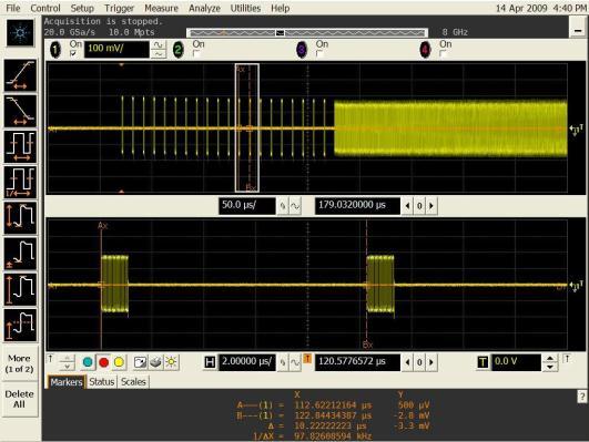
12 How Do Real Time Scopes Measure Jitter on Data? NRZ Serial Data Recovered Clock Jitter Trend Jitter Spectrum Units in Time Units in Time Jitter Histogram Page 12
13 How Do Real Time Scopes Measure Jitter on Data? NRZ Serial Data Recovered Clock Jitter Trend Jitter Spectrum Units in Time Units in Time Jitter Histogram Page 13
14 Where Does Jitter Come From? Transmitter Media Receiver Lossy interconnect (ISI) Impedance mismatches (ISI) Crosstalk (PJ) Thermal Noise (RJ) DutyCycle Distortion (DCD) Power Supply Noise (RJ, PJ) On chip coupling (PJ) Termination Errors (ISI) Thermal Noise (RJ) DutyCycle Distortion (DCD) Power Supply Noise (RJ, PJ) On chip coupling (PJ) Page 14

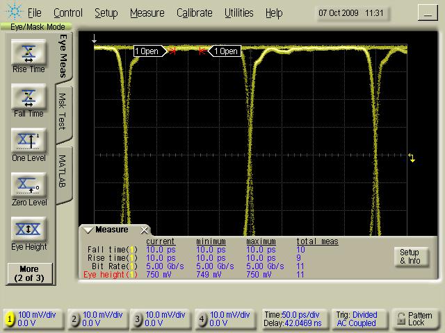
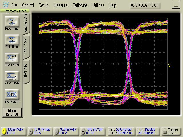
15 The Eye Diagram and Sampling Point E 1 Single transition Left Edge Nominal Sampling Point Eye Crossing Points Right Edge E 0 x = 0 x = 1/2 T x = T The EYE Diagram Unit Interval Oscilloscope Eye Overlaid transitions Total Jitter, J PP Ideal Sampling Point Probability Density Function Page 15

16 What is the Eye Diagram? Eye Diagrams Superimposed Bit Sequences Page 16 ADVA Training 86100C DCA-J Basics

17 Why Do We Care About Jitter? The only reason we analyze jitter is to Limit the Bit Error Ratio! A low Signal to Noise Ratio causes errors Voltage Noise vertical fluctuations across the sampling point Undesirable Amplitude Modulation Jitter describes the same effect but horizontally timing noise Jitter horizontal fluctuations across the sampling point Undesirable Phase Modulation Page 17

18 Which Eye Has Worse Jitter? A B You can t know unless you measure the Total Jitter or measure the jitter components! Page 18
 j UB (t) Random Jitter (RJ) j UB (t)= Gaussian Inter-symbol Interference (ISI) j B (t)=f(bw, data) Duty Cycle Distortion (DCD) j B (t)= d Periodic Jitter PJ j B (t)=a")
19 Decomposing Jitter Signal jitter can be composed of several types from several mechanisms Data-Correlated j B (t) Total Jitter (TJ) Data-Uncorrelated j B (t) Deterministic Jitter (DJ) j UB (t) Random Jitter (RJ) j UB (t)= Gaussian Inter-symbol Interference (ISI) j B (t)=f(bw, data) Duty Cycle Distortion (DCD) j B (t)= d Periodic Jitter PJ j B (t)=a sin(2pft)

20 Agilent Fixture De-embedding & Equalization
21 Source of Measurement Inaccuracies impedance mismatches probing effects smaller geometries test cables and adapters fixturing device packaging, etc. SCOPE NOISE FLOOR! There are multiple ways to offset these measurement impairments. calibration methods mathematical signal processing de-embedding/embedding techniques Scope noise can be amplified by de-embedding techniques


22 Connector Connector De-embedding Loss Compensation or Gain Function (De-convolve) Compensate for Probing and Fixture Loss Add Margin to Transmitter Characterization PCI Express, SATA, and Custom Compliance Requirement for Gen 2, 3 Tx PHY Channel S4P Rx PHY
 Virtual Probe and")


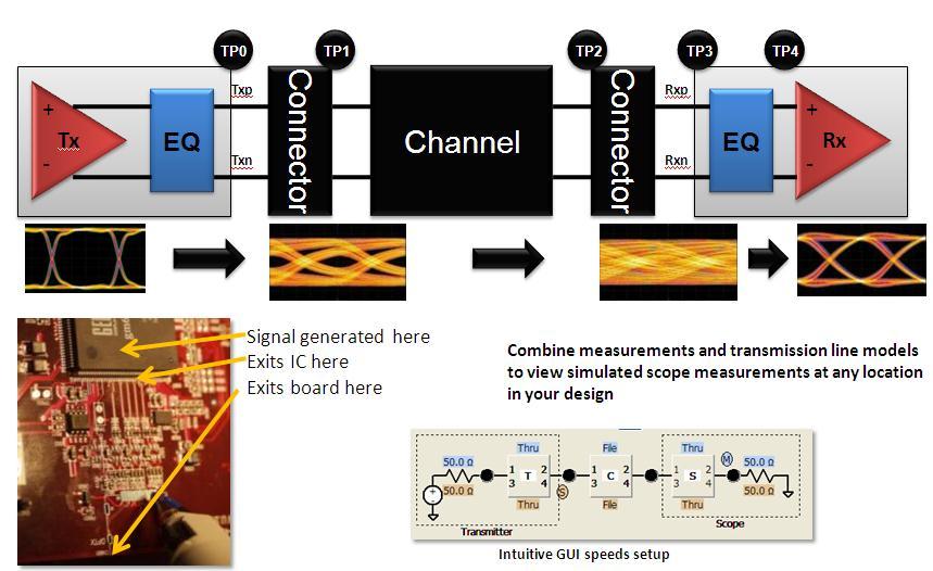
23 Connector Connector Embedding Loss Function (Convolve) Virtual Probe and Deemphasis/Equalization Connector Pin Rx TP1 TP2 TP3 Simulate Channel Loss on Signal Measured at Tx Simulate Equalization/Deemphasis at Rx Tx Signal Tx PHY Channel Channel.s4p+ conn.s4p+package.s4p Rx PHY Virtual Probe Rx Equalization TP1 TP3 TP2

24 Waveform Transformation Waveform Transformation maps an acquired waveform to another waveform mathematically using a transfer function model of the customer s system. The system may be real using actual customer components or may be virtual. Components may be described using RLC or S-Parameters. Look Here Look Here Look Here M Digital Source Connector Fixture Cable Cable Model And Look Here!

25 Product Briefing for N5465A Measure anywhere! Listen for these words: - De-Embedding - Fixture Removal - Cable Insertion - Virtual Probing - Probe Loading compensation InfiniiSim Waveform Transformation Toolset enables our customers to define the measurement environment to obtain the best measurement possible.

26 <Product> Position versus other Agilent Products <Visual of where <product> is positioned in product family> Probe at VIA De-embed Probe Probe at BGA RT BGA = 390 ps RT VIA = 183 ps RT De-embed = 175 ps


27 Serial Data Equalization Software for Infiniium Series Oscilloscopes DFE CTLE FFE automatic tap optimization Up to 40 Tabs


28 Transmitter De-emphasis We can account for loss through the channel at the transmitter with transmitter de-emphasis. De-emphasis off, measured at receiver De-emphasis is also called preemphasis. The amount of de-emphasis may be programmable. De-emphasis on, measured at transmitter De-emphasis on, measured at receiver


29 Key measure is eye quality Unequalized 1Gb/s Unequalized 3Gb/s Unequalized 5Gb/s Unequalized 8Gb/s
30 Feed-Forward Equalization r(t-ntd) is the input waveform n tap delays before the present time TD is the tap delay Cn is the nth coefficient (tap e(t) is the equalized waveform at time t Each voltage level is multiplied by its corresponding tap value and then all of these products are summed together to give the new equalized voltage for the location of interest
 V(k) is the correction voltage added to the decision threshold used when determining the logic value of bit k.")
31 Decision Feedback Equalization r(t) is the unequalized analog waveform voltage at time t s(k n) is the logic value (either upper target or lower target) for the bit n tap delays prior to the current bit Cn is the nth coefficient (tap) V(k) is the correction voltage added to the decision threshold used when determining the logic value of bit k. Each previous bit used in the algorithm is determined to be either high or low and is then multiplied by its corresponding tap value. These voltage/tap products are summed to determine how much to shift the waveform relative to the logical decision threshold.
32 Differentiation between FFE & DFE Uses voltage levels of the received waveform associated with previous and current bits to correct the voltage level of the current bit 2x taps can open up the eye dramatically Makes logical decisions (zero or one) and then feeds that information back to help determinie whether the current bit is a 1 or 0. The only location of the eye that a receiver sees is at the clock (center of the eye).


33 N5461A SDE software: Equalization for 5Gb/s Unequalized(5Gb/s): upper left FFE: lower middle 2 taps Eye width of 1/3 DFE: lower right 3 taps Eye width of 0 FFE DFE


34 Equalizer Setup Window for FFE and DFE settings
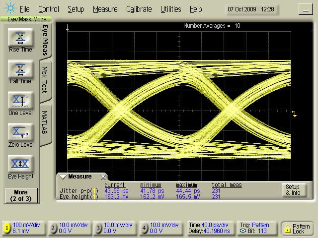
35 Precision Probe Characterize and correct for cable, switch, and test fixture loss using only an oscilloscope
36 The Importance of a Flat Frequency Response Why do we care about a flat frequency response? - The flatter the response the more accurately the scope will depict the signal - Measurements become more repeatable Frequency response of the Agilent X- Series
37 Cables and channels are lossy Response of cable rated to 20 GHz Notice that the 3dB down point is actually at 18 GHz instead of 20 GHz Bandwidth roll-off means attenuated signal at high bandwidth Frequency response is not flat
38 Every input path in a switch can vary A real life example: 112 different inputs, every one with slightly different loss, phase, and response characteristics Measurements can from channel to channel Technologies continue to push us to use more inputs (for example: PCIE gen3 now has 16 inputs) How much actual bandwidth does this system have?
39 Every input path in a switch can vary A real life example: 112 different inputs, every one with slightly different loss, phase, and response characteristics Measurements can from channel to channel Technologies continue to push us to use more inputs (for example: PCIE gen3 now has 16 inputs) Customer thought: 12 GHz BW Actual: 4.5 GHz BW

40 Why is this an issue? Inaccurate, non-repeatable measurements Solution? The solution is to: 1. Understand what the characteristic of the system is, and 2. Compensate for this system variation


41 Traditional De-embedding Takes Time Option 1: Six steps (you would need to do the following) Find a VNA Find someone that knows how to use a VNA and measure the cable Create s- parameter file Save s-parameter file to thumbdrive and load on scope Learn waveform transformation software and correctly remove loss Analyze the data As a result, we tend to choose to ignore the cable loss and channel variation entirely


42 How it works Agilent s X- Series uses its world class 200 GHz Indium Phosphide technology to provide a <15ps edge to the oscilloscope Comparing the baseline measurement with the cables influence, proper characterization is done and corrections can be made Infiniium s custom InP calibration edge Fast edge or Baseline Calibration edge is then measured by the X-Series Edge with lossy cable Lossy cable is then measured against the fast edge


43 PrecisionProbe: 3 Easy Steps 1. Measure baseline 2. Measure loss due to cable 3. Save File

44 Cables: The result Applied corrected filter Corrected cable response Response of cable with no correction
45 Cable correction results Before PrecisionProbe After PrecisionProbe S21 cable loss is removed through compensation Rise Time improves from 67 ps to 21 ps!

46 Jitter results Before PrecisionProbe S21 cable loss is removed through compensation Notice how there is 50% less ISI on the corrected waveform, resulting in less Total Jitter After PrecisionProbe
47 The real time eye Results: More margins! 20% less jitter 33% more eye height Slightly wider eye
48 Cabled Environment Benefits By characterizing and compensating for cable loss increased margins. Higher accuracy Faster than traditional VNA/de-embedding method


49 Probe characteristics are different from probe to probe 1. InfiniiMax II browser will have a different voltage transfer function than in InfiniiMax III with a browser 2. Two InfiniiMax II s with a browser could be different 3. Even changing the span on a browser can change the voltage transfer function of a probe


50 Measuring the Probe No probe Probe 1. Measure baseline 3. Save File 2. Measure loss due to probe Improve your measurement quality


51 Probe characterization: final results Transfer function of probe with no correction 1. Transfer function is now flat for the entire bandwdith of the probe 2. 6dB of loss is now compensated

52 Summary: 1. Cables, probes, fixtures, switches are lossy and cause measurement errors Uncorrected 2. Traditional de-embedding technology is time-consuming and equipment intensive. 3. Precision Probe make deembedded incredibly simply. Corrected PrecisionProbe will further increase your margins without adding significant time or extra equipment


53 Protocol Decode on the Infiniium Series USB 2.0 Example Multi-tab protocol viewer, time aligned with analog Header view With formatted frame content Payload view Search by packet type Jump to next search The competition has no equivalent for any of these Agilent protocol features. 53

54 Agilent Decode Ease-of-Use Advantage Setup multiple decodes simultaneously and quickly switch back and forth between them in the Decode Listing window. This button automatically sets up the scope parameters for your specific decode. With this Auto Setup button, you can be decoding data in less than a minute. If you want to see what values were set during the Auto Setup process or if you want to change certain parameters, use this Manual Setup button.
 serial protocolls:")
55 Infiniium Protocol Analysis Timecorrelated Protocol detailled level Search and capture Multi Serial Bus Colorcoded representation Available for ALL (most) serial protocolls:

56 Supports both MSO Digital and Analog Channels I2C + SPI Example Using MSO channels for protocol decode Using analog channels for protocol decode


57 View decode in waveform area, or...


58 Simultaneous decode of up to 4 Serial Buses Protocol trigger/decode sources can come from any of the following: 4 analog channels +16 digital + 4 functions + 4 waveform memories Anticipated usage primarily for protocols with explicit clocks such as I 2 C, SPI, CAN, LIN, MIPI, USB 2.0, RS-232/UART...

59 InfiniScan the real nice way to trigger!! Apply up to 8 Zone to trigger the signal individually Trigger on Measurement parameters Find and trigger non-monotic Edges Serial Pattern Trigger

60 InfiniScan the real nice way to trigger!!


61 Market Trends 1. Analog continues to go digital Vinyl record Videotape Photo Camera Cellphone CD DVD, Blue Ray Digital Camera Digital Cellphone 2. More integration at lower cost 3. Higher speed and lower power 4. High reliability delivered in less time
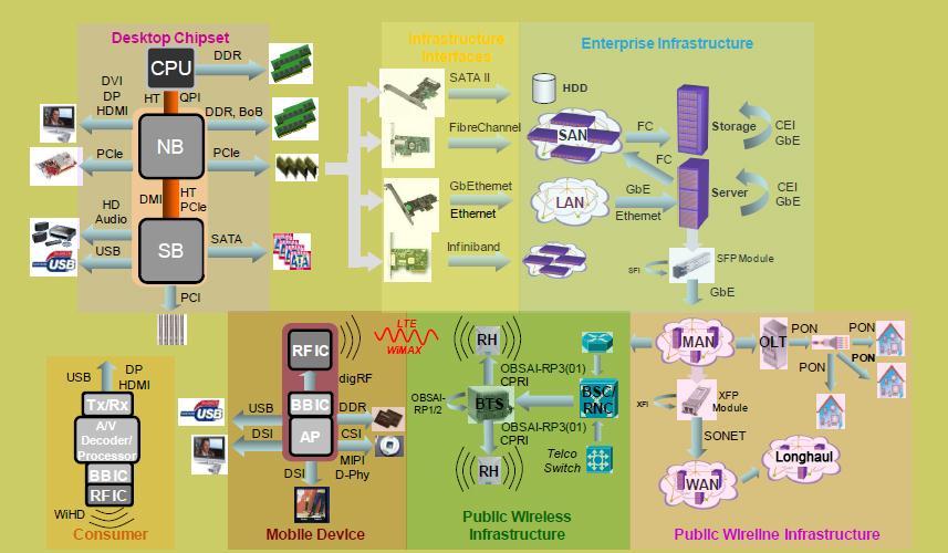
62 Ecosystem

 USB-Implementers Forum (USB-IF) Mobile Industry")

63 Agilent Digital Test Standards Program Our solutions are driven and supported by Agilent experts involved in international standards committees: Joint Electronic Devices Engineering Council (JEDEC) PCI Special Interest Group (PCI-SIG ) Video Electronics Standards Association (VESA) Serial ATA International Organization (SATA-IO) USB-Implementers Forum (USB-IF) Mobile Industry Processor Interface (MIPI) Alliance Optical Internetworking Forum (OIF) We re active in standards meetings, workshops, plugfests, and seminars Our customers test with highest confidence and achieve compliance faster


64 We understand your future requirements, because we help shape them Rick Eads PCI-Sig Board Member Brian Fetz DisplayPort Phy CTS Editor VESA Board Member Jim Choate USB-IF Compliance Committee USB 3.0 Electrical Test Spec WG Min-Jie Chong SATA/SAS PHY Contributor MIPI-PHY WG Contributor Roland Scherzinger MIPI Contributor The Agilent Pyramid team maintains engagement in the top high tech standards organizations SATA / SAS Test Challenges Page 64 Agilent Restricted


65 A Digital system: Serial Data Link Life Cycle of a Transported bit Die Bonding wire/pins PC transmission line Standard connector Cable Standard connector PC transmission line Bonding wire/pins Die Starts in here and ends in here Page 65 HIT 2011 Agilent Restricted March 2011


66 ADS EMPro, and SystemVue Pulse Pattern Generator Infiniium X-Series More Info A range of essential tools measurement and simulation that will help you cut through the challenges of gigabit digital designs. Blog: N1930B Physical Layer Test System (PLTS) Series Logic Analyzers Bit Error Ratio Testers (BERTs) 86100D Infiniium DCA-X ENA-TDR 66 HIT 2011 Agilent Restricted March 2011
67 SuperSpeed Communication Physical Layer Focus Point to point communication, concurrent data flow Low power mode Link training Independent clock domains both using Spread Spectrum Clocking (SSC) Non- Super Speed TX RX TX RX Non- Super Speed Super Speed TX RX RX TX Super Speed -or- -or- Transmitter (TX) De-emphasis 8B/10B coding Data scrambling Insertion of Skip Cable / Channel Backward compatible EMI requirements Signal integrity requirements Receiver (RX) Channel equalization Clock recovery Re-timing (deletion or insertion of addition Skips) How to handle USB 3.0 physical layer test requirements October 28, 2009
 TX RX Channel / Cable TX")


68 Physical Layer Test Solutions Non- Super Speed Super Speed -or- -or- TX Trans- RX mitter (TX) TX RX Channel / Cable TX Non- Super RX Receiver Speed RX TX (RX) Super Speed Agilent series Infiniium Oscilloscopes Agilent U7243A USB 3.0 Transmitter Compliance Test Software Agilent E5071C Network Analyzer 86100C DCA-J TDR Agilent J-BERT N4903B with N4916A/B De-emphasis Signal Converter Agilent 81250A ParBERT All physical layer tests: test adapter Agilent U7242A USB 3.0 Test Fixture N5990A Automated Compliance and Characterization Test Software How to handle USB 3.0 physical layer test requirements October 28, 2009
69 SuperSpeed Measurement Requirements Transmitter Compliance Testing: Compliance will be measured at the end of the compliance channel SMA termination for TX signals, phase matched SMA cable Terminate link under test with high speed oscilloscope Measure transmitted waveform with high speed oscilloscope Use compliance pattern 1M UI of data Compute: eye diagram, Rj, Dj, BER, average data rate, rise/fall time, Test requirement for SSC Slew Rate USB 3.0 Technical Review Page

70 Transmitter test requirements USB 3.0 Technical Review Page


71 Compliance Channels Compliance Channels are being developed to test SQ for worst case channel conditions Back panel USB route solution Channel loss will dominate Front Panel USB route solution Reflections will dominate losses Back Panel Front Panel USB 3.0 Technical Review Page
72 USB 3.0 Test fixture Support for Tx and Rx Testing SMA edge launch terminations SS A and SS B for host, device or cross hub testing USB 3.0 Test Fixtures (available now) Early Customer Needs and Development USB 3.0 Technical Review Page

73 Normative Transmitter Compliance Test Setup Scope SMA TP0 DSO 90K Scope SMA USB 3.0 Technical Review Page


74 USB 3.0 Technical Review Page


75 Summary report of testing with Statistics USB 3.0 Technical Review Page

76 Agilent TX Compliance and Validation Solution Report Summary TX Compliance Test With USB Org Test Tool USB 3.0 Technical Review Page
77 USB 3.0 Protocol Decode: on scope Page 77


78 SS Test Adapter Eliminate All Doubt: 5Gb/s Test Signal Example No SSC, Sj / Rj shown on screen shots 1 50Ω 50Ω trigger 2 N4915A-005 Switch Channe l 3 TP RX - + TX - How to handle USB 3.0 physical layer test requirements October 28, 2009


79 Typical SuperSpeed Link Turn-on Sequence LTSSM states: Host Power-up Rx. Detect. Reset Rx. Detect. Active Polling. LFPS Polling. RxEQ Polling. Active Polling. Configuration Polling. Idle Loopback warm reset de-assert termination detected LFPS handshake TSEQ transmitted TS1 received TS2 received if directed Device Complianc e warm reset Rx. Detect. Reset Rx. Detect. Active Polling. LFPS Polling. RxEQ Polling. Active Polling. Configuration Polling. Idle Loopback multiple states Power-up How to handle USB 3.0 physical layer test requirements October 28, 2009


80 Characteristical Eye Closure by Sinusoidal Jitter Eye Diagram BER Scan How to handle USB 3.0 physical layer test requirements October 28, 2009

 pins Receiver (RX) elastic buffer compensates for clock difference How to handle USB")
81 Why is Spread Spectrum Clocking Included in Receiver Compliance Test? SSC stresses clock recovery and elastic buffer, required for compliance test Max. SSC deviation is 5000ppm, modulation rate between 30kHz and 33kHz Nominal data rate: 5Gb/s Frequency downspread: 5000ppm i.e Gb/s Receiver EQ FF CR TX Non-SS SuperSpeed RX RX loop- error back count TX read 1 2 -or- 1 2 skp s k p skp s k p skp s k p s k p s k p s kp s kp s kp s kp s kp s kp s p k p s k Original un-modulated data at 5Gb/s Data with SSC at receiver (RX) pins Receiver (RX) elastic buffer compensates for clock difference How to handle USB 3.0 physical layer test requirements October 28, 2009


82 Characteristical Eye Closure by Random Jitter Eye Diagram BER Scan bounded Rj unbounded Rj How to handle USB 3.0 physical layer test requirements October 28, 2009


83 Hands-on in der Ausstellung Herzlichen Dank für Ihr Interesse
84 Thank you for Attending Questions? USB 3.0 Technical Review Page
Emphasis, Equalization & Embedding
 Emphasis, Equalization & Embedding Cleaning the Rusty Channel Gustaaf Sutorius Application Engineer Agilent Technologies gustaaf_sutorius@agilent.com Dr. Thomas Kirchner Senior Application Engineer Digital
Combating Closed Eyes Design & Measurement of Pre-Emphasis and Equalization for Lossy Channels
 Combating Closed Eyes Design & Measurement of Pre-Emphasis and Equalization for Lossy Channels Why Test the Receiver? Serial Data communications standards have always specified both the transmitter and
Combating Closed Eyes Design & Measurement of Pre-Emphasis and Equalization for Lossy Channels
 Combating Closed Eyes Design & Measurement of Pre-Emphasis and Equalization for Lossy Channels Why Test the Receiver? Serial Data communications standards have always specified both the transmitter and
Receiver Testing to Third Generation Standards. Jim Dunford, October 2011
 Receiver Testing to Third Generation Standards Jim Dunford, October 2011 Agenda 1.Introduction 2. Stressed Eye 3. System Aspects 4. Beyond Compliance 5. Resources 6. Receiver Test Demonstration PCI Express
PAM4 signals for 400 Gbps: acquisition for measurement and signal processing
 TITLE PAM4 signals for 400 Gbps: acquisition for measurement and signal processing Image V1.00 1 Introduction, content High speed serial data links are in the process in increasing line speeds from 25
Draft Baseline Proposal for CDAUI-8 Chipto-Module (C2M) Electrical Interface (NRZ)
 Electrical Interface (NRZ)") Draft Baseline Proposal for CDAUI-8 Chipto-Module (C2M) Electrical Interface (NRZ) Authors: Tom Palkert: MoSys Jeff Trombley, Haoli Qian: Credo Date: Dec. 4 2014 Presented: IEEE 802.3bs electrical interface
Draft Baseline Proposal for CDAUI-8 Chipto-Module (C2M) Electrical Interface (NRZ) Authors: Tom Palkert: MoSys Jeff Trombley, Haoli Qian: Credo Date: Dec. 4 2014 Presented: IEEE 802.3bs electrical interface
USB3.1 / Type-C / Power Delivery Test Challenge and Solution
 Woo Jun-Hyung / Choi Seok-Keun USB3.1 / Type-C / Power Delivery Test Challenge and Solution Page USB Type C Connector and USB3.1 Test Solution Agenda Page 3 Introduction to the USB Type C Connector USB3.1
PCI Express. Francis Liu Project Manager Agilent Technologies. Nov 2012
 PCI Express Francis Liu Project Manager Agilent Technologies Nov 2012 PCI Express 3.0 Agilent Total Solution Physical layer interconnect design Physical layertransmitter test Physical layerreceiver test
Prepare for Next Generation USB Technology Testing
 Prepare for Next Generation USB Technology Testing Disclaimer The USB 3.1 compliance test requirements are not final therefore all opinions, judgments, recommendations, etc., that are presented herein
Eye Doctor II Advanced Signal Integrity Tools
 Eye Doctor II Advanced Signal Integrity Tools EYE DOCTOR II ADVANCED SIGNAL INTEGRITY TOOLS Key Features Eye Doctor II provides the channel emulation and de-embedding tools Adds precision to signal integrity
How advances in digitizer technologies improve measurement accuracy
 How advances in digitizer technologies improve measurement accuracy Impacts of oscilloscope signal integrity Oscilloscopes Page 2 By choosing an oscilloscope with superior signal integrity you get the
Why Engineers Ignore Cable Loss
 Why Engineers Ignore Cable Loss By Brig Asay, Agilent Technologies Companies spend large amounts of money on test and measurement equipment. One of the largest purchases for high speed designers is a real
Practical De-embedding for Gigabit fixture. Ben Chia Senior Signal Integrity Consultant 5/17/2011
 Practical De-embedding for Gigabit fixture Ben Chia Senior Signal Integrity Consultant 5/17/2011 Topics Why De-Embedding/Embedding? De-embedding in Time Domain De-embedding in Frequency Domain De-embedding
SV1C Personalized SerDes Tester
 SV1C Personalized SerDes Tester Data Sheet SV1C Personalized SerDes Tester Data Sheet Revision: 1.0 2013-02-27 Revision Revision History Date 1.0 Document release Feb 27, 2013 The information in this
Tektronix Inc. DisplayPort Standard
 DisplayPort Standard 06-12-2008 DisplayPort Standard Tektronix MOI for Sink Tests (AWG Jitter Generation using Direct Synthesis and calibration using Real Time DPO measurements for Sink Devices) DisplayPort
100G EDR and QSFP+ Cable Test Solutions
 100G EDR and QSFP+ Cable Test Solutions (IBTA, 100GbE, CEI) DesignCon 2017 James Morgante Anritsu Company Presenter Bio James Morgante Application Engineer Eastern United States james.morgante@anritsu.com
GT Dual-Row Nano Vertical SMT High Speed Characterization Report For Differential Data Applications
 GT-16-95 Dual-Row Nano Vertical SMT For Differential Data Applications 891-011-15S Vertical SMT PCB 891-001-15P Cable Mount Revision History Rev Date Approved Description A 6/3/2016 R. Ghiselli/D. Armani
SDLA Visualizer Serial Data Link Analysis Visualizer Software Printable Application Help
 SDLA Visualizer Serial Data Link Analysis Visualizer Software Printable Application Help *P076017306* 076-0173-06 SDLA Visualizer Serial Data Link Analysis Visualizer Software Printable Application Help
SDAIII-CompleteLinQ Multi-Lane Serial Data, Noise and Crosstalk Analysis
 SDAIII-CompleteLinQ Multi-Lane Serial Data, Noise and Crosstalk Analysis TOOLS TO MEET SERIAL DATA ANALYSIS CHALLENGES Key Features Most complete jitter decomposition, eye diagram and analysis tools Up
Synthesized Clock Generator
 Synthesized Clock Generator CG635 DC to 2.05 GHz low-jitter clock generator Clocks from DC to 2.05 GHz Random jitter
Switching Solutions for Multi-Channel High Speed Serial Port Testing
 Switching Solutions for Multi-Channel High Speed Serial Port Testing Application Note by Robert Waldeck VP Business Development, ASCOR Switching The instruments used in High Speed Serial Port testing are
Logic Analysis Basics
 Logic Analysis Basics September 27, 2006 presented by: Alex Dickson Copyright 2003 Agilent Technologies, Inc. Introduction If you have ever asked yourself these questions: What is a logic analyzer? What
Logic Analysis Basics
 Logic Analysis Basics September 27, 2006 presented by: Alex Dickson Copyright 2003 Agilent Technologies, Inc. Introduction If you have ever asked yourself these questions: What is a logic analyzer? What
M809256PA OIF-CEI CEI-56G Pre-Compliance Receiver Test Application
 M809256PA OIF-CEI CEI-56G Pre-Compliance Receiver Test Application Find us at www.keysight.com Page 1 Table of Contents Key Features... 3 Description... 3 Calibrations and Tests Covered by M809256PA Pre-Compliance
Agilent Technologies Pulse Pattern and Data Generators Digital Stimulus Solutions
 Agilent Technologies Pattern and Data Generators Digital Stimulus Solutions Leading pulse, pattern, data and clock generation for all test needs in digital design and manufacturing Pattern Generators Agilent
GT Dual-Row Nano Vertical Thru-Hole High Speed Characterization Report For Differential Data Applications
 GT-16-97 Dual-Row Nano Vertical Thru-Hole For Differential Data Applications 891-007-15S Vertical Thru-Hole PCB 891-001-15P Cable Mount Revision History Rev Date Approved Description A 8/31/2016 R. Ghiselli/G.
Agilent E4887A HDMI TMDS Signal Generator Platform
 Agilent E4887A HDMI TMDS Signal Generator Platform Data Sheet Version 1.9 Preliminary E4887A- 007 E4887A- 037 E4887A- 003 Page Convenient Compliance Testing and Characterization of HDMI 1.3 Devices The
QPHY-USB3 USB3.0 Serial Data Operator s Manual
 QPHY-USB3 USB3.0 Serial Data Operator s Manual Revision A April, 2009 Relating to the Following Release Versions: Software Option Rev. 5.8 USB3 Script Rev. 1.0 Style Sheet Rev. 1.2 LeCroy Corporation 700
PicoScope 6407 Digitizer
 YE AR PicoScope 6407 Digitizer HIGH PERFORMANCE USB DIGITIZER Programmable and Powerful 1 GHz bandwidth 1 GS buffer size 5 GS/s real-time sampling Advanced digital triggers Built-in function generator
Comparison of NRZ, PR-2, and PR-4 signaling. Qasim Chaudry Adam Healey Greg Sheets
 Comparison of NRZ, PR-2, and PR-4 signaling Presented by: Rob Brink Contributors: Pervez Aziz Qasim Chaudry Adam Healey Greg Sheets Scope and Purpose Operation over electrical backplanes at 10.3125Gb/s
SV1C Personalized SerDes Tester. Data Sheet
 SV1C Personalized SerDes Tester Data Sheet Table of Contents 1 Table of Contents Table of Contents Table of Contents... 2 List of Figures... 3 List of Tables... 3 Introduction... 4 Overview... 4 Key Benefits...
DisplayPort TX & RX Testing Solutions
 DisplayPort TX & RX Testing Solutions Agenda DP Technology Overview DPC TX Solution DPC RX Solution 2 DP Technology Overview 3 DisplayPort Standards Standards DP 1.2 May, 2012 DP over Type-C Spec Aug,
Advanced Troubleshooting with Oscilloscopes 9000 Scope Hands-on Labs
 Advanced Troubleshooting with Oscilloscopes 9000 Scope Hands-on Labs Page Lab 1: Scope-based Protocol Analysis 2 Lab 2: Measurements & Analysis 10 Lab 3: InfiniiScan Zone-qualified Triggering 19 Lab 4:
Manual Supplement. This supplement contains information necessary to ensure the accuracy of the above manual.
 Manual Title: 9500B Users Supplement Issue: 2 Part Number: 1625019 Issue Date: 9/06 Print Date: October 2005 Page Count: 6 Version 11 This supplement contains information necessary to ensure the accuracy
BRR Tektronix BroadR-Reach Compliance Solution for Automotive Ethernet. Anshuman Bhat Product Manager
 BRR Tektronix BroadR-Reach Compliance Solution for Automotive Ethernet Anshuman Bhat Product Manager anshuman.bhat@tektronix.com Agenda BroadR-Reach Automotive Market Technology Overview Open Alliance
立肯科技 LeColn Technology
 DisplayPort PHY Validation 立肯科技 LeColn Technology 1 DisplayPort Basics Maximum bit rate DP1.2b 1.62Gb/s( RBR = reduced bit rate) 2.7Gb/s( HBR = high bit rate) 5.4Gb/s( HBR2 =high bit rate 2) DP1.3/1.4
Keysight Technologies M8048A ISI Channels
 Keysight Technologies M8048A ISI Channels Master Your Next Designs Data Sheet Key features Emulate a wide range of channel loss with cascadable ISI traces with fine resolution 4 short (7.7 to 12.8 ) and
Draft 100G SR4 TxVEC - TDP Update. John Petrilla: Avago Technologies February 2014
 Draft 100G SR4 TxVEC - TDP Update John Petrilla: Avago Technologies February 2014 Supporters David Cunningham Jonathan King Patrick Decker Avago Technologies Finisar Oracle MMF ad hoc February 2014 Avago
MSO-28 Oscilloscope, Logic Analyzer, Spectrum Analyzer
 Link Instruments Innovative Test & Measurement solutions since 1986 Store Support Oscilloscopes Logic Analyzers Pattern Generators Accessories MSO-28 Oscilloscope, Logic Analyzer, Spectrum Analyzer $ The
Keysight Technologies CAN/LIN Measurements (Option AMS) for InfiniiVision Series Oscilloscopes
 for InfiniiVision Series Oscilloscopes") Ihr Spezialist für Mess- und Prüfgeräte Keysight Technologies CAN/LIN Measurements (Option AMS) for InfiniiVision Series Oscilloscopes Data Sheet Introduction Debug the signal integrity of your CAN and
Ihr Spezialist für Mess- und Prüfgeräte Keysight Technologies CAN/LIN Measurements (Option AMS) for InfiniiVision Series Oscilloscopes Data Sheet Introduction Debug the signal integrity of your CAN and
Keysight Technologies HDMI and DisplayPort Design and Test A Better Way. Thorough characterization and validation of your display designs
 Keysight Technologies HDMI and DisplayPort Design and Test A Better Way Thorough characterization and validation of your display designs New Challenges Transmitter TP1 TP2 Sink (Display) Data Tx TMDS (AV
InfiniBand Trade Association
 InfiniBand Trade Association Revision 1.02 3/30/2014 IBTA Receiver MOI for FDR Devices For Anritsu MP1800A Signal Analyzer and Agilent 86100D with module 86108B and FlexDCA S/W for stressed signal calibration
GHz Sampling Design Challenge
 GHz Sampling Design Challenge 1 National Semiconductor Ghz Ultra High Speed ADCs Target Applications Test & Measurement Communications Transceivers Ranging Applications (Lidar/Radar) Set-top box direct
Exceeding the Limits of Binary Data Transmission on Printed Circuit Boards by Multilevel Signaling
 Exceeding the Limits of Binary Data Transmission on Printed Circuit Boards by Multilevel Signaling Markus Grözing, Manfred Berroth INT, in cooperation with Michael May Agilent Technologies, Böblingen Prof.
PicoScope 6407 Digitizer
 YE AR HIGH PERFORMANCE USB DIGITIZER Programmable and Powerful 1 GHz bandwidth 1 GS buffer size 5 GS/s real-time sampling Advanced digital triggers Built-in function generator USB-connected Signals Analysis
Meeting Embedded Design Challenges with Mixed Signal Oscilloscopes
 Meeting Embedded Design Challenges with Mixed Signal Oscilloscopes Introduction Embedded design and especially design work utilizing low speed serial signaling is one of the fastest growing areas of digital
Next Generation 인터페이스테크놀로지트렌드
 Next Generation 인터페이스테크놀로지트렌드 (USB3.1, HDMI2.0, MHL3.2) 텍트로닉스박영준부장 Agenda USB3.1 Compliance Test update What s different for USB3.1 Transmitter and Receiver Compliance Test HDMI2.0, MHL3.2 overview Q &
InfiniBand Trade Association
 InfiniBand Trade Association Revision 1.04 2/27/2014 IBTA Receiver MOI for FDR Devices For Tektronix BERTScope Bit Error Rate Tester and Agilent 86100D with module 86108B and FlexDCA S/W for stressed signal
High-Speed Digital Interface 4.0 (PCIe, SAS) Insight and Test Solutions. Francis Liu Senior Project Manager Keysight Technologies
 Insight and Test Solutions. Francis Liu Senior Project Manager Keysight Technologies") High-Speed Digital Interface 4.0 (PCIe, SAS) Insight and Test Solutions Francis Liu Senior Project Manager Keysight Technologies Page 1 Agenda PCIe 4.0 Ecosystem and Timeline PCIe 4.0 TX Testing and Tools
High-Speed Digital Interface 4.0 (PCIe, SAS) Insight and Test Solutions Francis Liu Senior Project Manager Keysight Technologies Page 1 Agenda PCIe 4.0 Ecosystem and Timeline PCIe 4.0 TX Testing and Tools
Agilent MOI for HDMI 1.4b Cable Assembly Test Revision Jul 2012
 Revision 1.11 19-Jul 2012 Agilent Method of Implementation (MOI) for HDMI 1.4b Cable Assembly Test Using Agilent E5071C ENA Network Analyzer Option TDR 1 Table of Contents 1. Modification Record... 4 2.
Agilent 86100C Infiniium DCA-J
 Agilent 86100C Infiniium DCA-J The fastest way to the right answer Time Domain Reflectometer Digital Communications Analyzer The multi-functional analysis tool Wide Band Oscilloscope Jitter Analyzer DCA-J:
32 G/64 Gbaud Multi Channel PAM4 BERT
 Product Introduction 32 G/64 Gbaud Multi Channel PAM4 BERT PAM4 PPG MU196020A PAM4 ED MU196040A Signal Quality Analyzer-R MP1900A Series Outline of MP1900A series PAM4 BERT Supports bit error rate measurements
Memory-Depth Requirements for Serial Data Analysis in a Real-Time Oscilloscope
 Memory-Depth Requirements for Serial Data Analysis in a Real-Time Oscilloscope Application Note 1495 Table of Contents Introduction....................... 1 Low-frequency, or infrequently occurring jitter.....................
Next Generation Ultra-High speed standards measurements of Optical and Electrical signals
 Next Generation Ultra-High speed standards measurements of Optical and Electrical signals Apr. 2011, V 1.0, prz Agenda Speeds above 10 Gb/s: Transmitter and Receiver test setup Transmitter Test 1,2 : Interconnect,
SMPTE STANDARD Gb/s Signal/Data Serial Interface. Proposed SMPTE Standard for Television SMPTE 424M Date: < > TP Rev 0
 Proposed SMPTE Standard for Television Date: TP Rev 0 SMPTE 424M-2005 SMPTE Technology Committee N 26 on File Management and Networking Technology SMPTE STANDARD- --- 3 Gb/s Signal/Data Serial
Jitter and Eye Fundamental & Application. Jacky Huang AE, Tektronix Taiwan
 Jitter and Eye Fundamental & Application Jacky Huang AE, Tektronix Taiwan Agenda Background Information Jitter Basics What is Jitter? TIE vs. Period Jitter vs. Cycle-to-Cycle Clock Recovery Jitter Visualization
New Serial Link Simulation Process, 6 Gbps SAS Case Study
 ew Serial Link Simulation Process, 6 Gbps SAS Case Study Donald Telian SI Consultant Session 7-TH2 Donald Telian SI Consultant About the Authors Donald Telian is an independent Signal Integrity Consultant.
USB 3.1 ENGINEERING CHANGE NOTICE
 Title: SSP System Jitter Budget Applied to: USB_3_1r1.0_07_31_2013 Brief description of the functional changes: Change to the 10Gbps system jitter budget. The change reduces the random jitter (RJ) budget
Analyzing 8b/10b Encoded Signals with a Real-time Oscilloscope Real-time triggering up to 6.25 Gb/s on 8b/10b encoded data streams
 Presented by TestEquity - www.testequity.com Analyzing 8b/10b Encoded Signals with a Real-time Oscilloscope Real-time triggering up to 6.25 Gb/s on 8b/10b encoded data streams Application Note Application
C-PHY Essentials Transmitter Test Solution TekExpress C-PHY Essentials Tx
 C-PHY Essentials Transmitter Test Solution TekExpress C-PHY Essentials Tx Applications Camera CMOS Image sensors Display Driver ICs Application processor for Mobile devices Tektronix C-PHY TX Essentials
40 Gb/s PatternPro Programmable Pattern Generator PPG4001 Datasheet
 40 Gb/s PatternPro Programmable Pattern Generator PPG4001 Datasheet Applications Semiconductor device testing Optical component testing Transceiver module testing The Tektronix PPG4001 PatternPro programmable
Solutions to Embedded System Design Challenges Part II
 Solutions to Embedded System Design Challenges Part II Time-Saving Tips to Improve Productivity In Embedded System Design, Validation and Debug Hi, my name is Mike Juliana. Welcome to today s elearning.
ECE 5765 Modern Communication Fall 2005, UMD Experiment 10: PRBS Messages, Eye Patterns & Noise Simulation using PRBS
 ECE 5765 Modern Communication Fall 2005, UMD Experiment 10: PRBS Messages, Eye Patterns & Noise Simulation using PRBS modules basic: SEQUENCE GENERATOR, TUNEABLE LPF, ADDER, BUFFER AMPLIFIER extra basic:
Agilent N5431A XAUI Electrical Validation Application
 Agilent N5431A XAUI Electrical Validation Application Methods of Implementation s Agilent Technologies Notices Agilent Technologies, Inc. 2008 No part of this manual may be reproduced in any form or by
CAN/LIN Measurements (Option AMS) for Agilent s InfiniiVision Series Oscilloscopes
 for Agilent s InfiniiVision Series Oscilloscopes") CAN/LIN Measurements (Option AMS) for Agilent s InfiniiVision Series Oscilloscopes Data Sheet Debug the signal integrity of your CAN and LIN designs faster Introduction The Agilent Technologies InfiniiVision
CAN/LIN Measurements (Option AMS) for Agilent s InfiniiVision Series Oscilloscopes Data Sheet Debug the signal integrity of your CAN and LIN designs faster Introduction The Agilent Technologies InfiniiVision
Electrical Sampling Modules Datasheet 80E11 80E11X1 80E10B 80E09B 80E08B 80E07B 80E04 80E03 80E03-NV
 Electrical Sampling Modules Datasheet 80E11 80E11X1 80E10B 80E09B 80E08B 80E07B 80E04 80E03 80E03-NV The DSA8300 Series Sampling Oscilloscope, when configured with one or more electrical sampling modules,
SignalTap Plus System Analyzer
 SignalTap Plus System Analyzer June 2000, ver. 1 Data Sheet Features Simultaneous internal programmable logic device (PLD) and external (board-level) logic analysis 32-channel external logic analyzer 166
Systematic Tx Eye Mask Definition. John Petrilla, Avago Technologies March 2009
 Systematic Tx Eye Mask Definition John Petrilla, Avago Technologies March 2009 Presentation Overview Problem statement & solution Comment Reference: P802.3ba D1.2, Comment 97 Reference Material Systematic
Serial Data Link Analysis Visualizer (SDLA Visualizer) Option SDLA64, DPOFL-SDLA64
 Option SDLA64, DPOFL-SDLA64") Serial Data Link Analysis Visualizer (SDLA Visualizer) Option SDLA64, DPOFL-SDLA64 SDLA Visualizer and DPOJET with simultaneous views of a PCI Express 3.0 acquired signal, signal after compliance channel
Serial Data Link Analysis Visualizer (SDLA Visualizer) Option SDLA64, DPOFL-SDLA64 SDLA Visualizer and DPOJET with simultaneous views of a PCI Express 3.0 acquired signal, signal after compliance channel
SDTV 1 DigitalSignal/Data - Serial Digital Interface
 SMPTE 2005 All rights reserved SMPTE Standard for Television Date: 2005-12 08 SMPTE 259M Revision of 259M - 1997 SMPTE Technology Committee N26 on File Management & Networking Technology TP Rev 1 SDTV
Keysight Method of Implementation (MOI) for VESA DisplayPort (DP) Standard Version 1.3 Cable-Connector Compliance Tests Using E5071C ENA Option TDR
 for VESA DisplayPort (DP) Standard Version 1.3 Cable-Connector Compliance Tests Using E5071C ENA Option TDR") Revision 1.00 February 27, 2015 Keysight Method of Implementation (MOI) for VESA DisplayPort (DP) Standard Version 1.3 Cable-Connector Compliance Tests Using E5071C ENA Option TDR 1 Table of Contents 1.
Revision 1.00 February 27, 2015 Keysight Method of Implementation (MOI) for VESA DisplayPort (DP) Standard Version 1.3 Cable-Connector Compliance Tests Using E5071C ENA Option TDR 1 Table of Contents 1.
2 MHz Lock-In Amplifier
 2 MHz Lock-In Amplifier SR865 2 MHz dual phase lock-in amplifier SR865 2 MHz Lock-In Amplifier 1 mhz to 2 MHz frequency range Dual reference mode Low-noise current and voltage inputs Touchscreen data display
CDAUI-8 Chip-to-Module (C2M) System Analysis #3. Ben Smith and Stephane Dallaire, Inphi Corporation IEEE 802.3bs, Bonita Springs, September 2015
 System Analysis #3. Ben Smith and Stephane Dallaire, Inphi Corporation IEEE 802.3bs, Bonita Springs, September 2015") CDAUI-8 Chip-to-Module (C2M) System Analysis #3 Ben Smith and Stephane Dallaire, Inphi Corporation IEEE 802.3bs, Bonita Springs, September 2015 Supporters Ali Ghiasi, Ghiasi Quantum LLC Marco Mazzini,
CDAUI-8 Chip-to-Module (C2M) System Analysis #3 Ben Smith and Stephane Dallaire, Inphi Corporation IEEE 802.3bs, Bonita Springs, September 2015 Supporters Ali Ghiasi, Ghiasi Quantum LLC Marco Mazzini,
WAVEEXPERT SERIES OSCILLOSCOPES WE 9000 NRO 9000 SDA 100G. The World s Fastest Oscilloscope
 WAVEEXPERT SERIES OSCILLOSCOPES WE 9000 NRO 9000 SDA 100G The World s Fastest Oscilloscope The Fastest Oscilloscope in the Marketplace The WaveExpert and SDA 100G are the first instruments to combine the
Generation of Novel Waveforms Using PSPL Pulse Generators
 Generation of Novel Waveforms Using PSPL Pulse Generators James R. Andrews, Ph.D, IEEE Fellow & Bob McLaughlin PSPL Founder & former President (retired) PSPL Sales Engineer Picosecond Pulse Labs (PSPL)
Benefits of the R&S RTO Oscilloscope's Digital Trigger. <Application Note> Products: R&S RTO Digital Oscilloscope
 Benefits of the R&S RTO Oscilloscope's Digital Trigger Application Note Products: R&S RTO Digital Oscilloscope The trigger is a key element of an oscilloscope. It captures specific signal events for detailed
PBR-310C E-BERT. 10Gb/s BERT System with Eye Diagram Tracer
 PBR-310C E-BERT 10Gb/s BERT System with Eye Diagram Tracer rate from 8.5~11.1Gb/s and extend data rate down to 125M~5Gb/s Support up to four channels Eye Diagram and Mask Test* Eye Contour and Histogram*
Datasheet SHF A
 SHF Communication Technologies AG Wilhelm-von-Siemens-Str. 23D 12277 Berlin Germany Phone +49 30 772051-0 Fax ++49 30 7531078 E-Mail: sales@shf.de Web: http://www.shf.de Datasheet SHF 19120 A 2.85 GSa/s
DisplayPort 1.4 Link Layer Compliance
 DisplayPort 1.4 Link Layer Compliance Neal Kendall Product Marketing Manager Teledyne LeCroy quantumdata Product Family neal.kendall@teledyne.com April 2018 Agenda DisplayPort 1.4 Source Link Layer Compliance
Agilent N6467A BroadR-Reach Compliance Test Application. Methods of Implementation
 Agilent N6467A BroadR-Reach Compliance Test Application Methods of Implementation s1 Notices Agilent Technologies, Inc. 2013 No part of this manual may be reproduced in any form or by any means (including
Ali Ghiasi. Nov 8, 2011 IEEE GNGOPTX Study Group Atlanta
 Ali Ghiasi Nov 8, 2011 IEEE 802.3 100GNGOPTX Study Group Atlanta 1 Overview I/O Trend Line card implementations VSR/CAUI-4 application model cppi-4 application model VSR loss budget Possible CAUI-4 loss
Technical Article MS-2714
 . MS-2714 Understanding s in the JESD204B Specification A High Speed ADC Perspective by Jonathan Harris, applications engineer, Analog Devices, Inc. INTRODUCTION As high speed ADCs move into the GSPS range,
FOM-1090 FOM-1090 FOM FOM-1090 w/ DB-25 Female FOM-1091 w/ DB-25 Male
 Serial Data Communications Synchronous, Asynchronous or Isochronous Signal rates: DC to 20 MHz FOM-1090 w/ DB-25 Female FOM-1091 w/ DB-25 Male Supported Interface Standards TIA-530, TIA-530A TIA-232 TIA-574
PCIe: EYE DIAGRAM ANALYSIS IN HYPERLYNX
 PCIe: EYE DIAGRAM ANALYSIS IN HYPERLYNX w w w. m e n t o r. c o m PCIe: Eye Diagram Analysis in HyperLynx PCI Express Tutorial This PCI Express tutorial will walk you through time-domain eye diagram analysis
ELECTRICAL PERFORMANCE REPORT
 CIRCUITS & DESIGN ELECTRICAL PERFORMANCE REPORT DENSIPAC 4 ROW Date: 06-12-2006 Circuits & Design EMEA Circuits & Design 1/21 06/12/2006 1 INTRODUCTION... 3 2 CONNECTORS, TEST BOARDS AND TEST EQUIPMENT...
100Gb/s Single-lane SERDES Discussion. Phil Sun, Credo Semiconductor IEEE New Ethernet Applications Ad Hoc May 24, 2017
 100Gb/s Single-lane SERDES Discussion Phil Sun, Credo Semiconductor IEEE 802.3 New Ethernet Applications Ad Hoc May 24, 2017 Introduction This contribution tries to share thoughts on 100Gb/s single-lane
Advanced Skills with Oscilloscopes
 Advanced Skills with Oscilloscopes A Hands On Laboratory Guide to Oscilloscopes using the Rigol DS1104Z By: Tom Briggs, Department of Computer Science & Engineering Shippensburg University of Pennsylvania
The Challenges of Measuring PAM4 Signals
 TITLE The Challenges of Measuring PAM4 Signals Panelists: Doug Burns, SiSoft Stephen Mueller, Teledyne LeCroy Luis Boluña, Keysight Technologies Mark Guenther, Tektronix Image Jose Moreira, Advantest Martin
Senior Project Manager / AEO
 Kenny Liao 2018.12.18&20 Senior Project Manager / AEO Measurement Demo Prepare instrument for measurement Calibration Fixture removal Conclusion What next? Future trends Resources Acquire channel data
Agilent N4876A 28 Gb/s Multiplexer 2:1
 Agilent N4876A 28 Gb/s Multiplexer 2:1 Data Sheet Revision 1.0 Features and Benefits Variable data rate up to 28.4 Gb/s Multiplexes two generator channels Front-end box for J-BERT or ParBERT Control via
Portable Performance for Debug and Validation
 WaveJet 300A Oscilloscopes 100 MHz 500 MHz Portable Performance for Debug and Validation A UNIQUE TOOLSET FOR PORTABLE OSCILLOSCOPES Key Features 100 MHz, 200 MHz, 350 MHz and 500 MHz bandwidths Sample
Optimizing BNC PCB Footprint Designs for Digital Video Equipment
 Optimizing BNC PCB Footprint Designs for Digital Video Equipment By Tsun-kit Chin Applications Engineer, Member of Technical Staff National Semiconductor Corp. Introduction An increasing number of video
Duobinary Transmission over ATCA Backplanes
 Duobinary Transmission over ATCA Backplanes Majid Barazande-Pour John Khoury November 15-19, 2004 IEEE 802.3ap Backplane Ethernet Task Force Plenary Meeting San Antonio Texas Outline Introduction Adaptive
MR Interface Analysis including Chord Signaling Options
 MR Interface Analysis including Chord Signaling Options David R Stauffer Margaret Wang Johnston Andy Stewart Amin Shokrollahi Kandou Bus SA May 12, 2014 Kandou Bus, S.A 1 Contribution Number: OIF2014.113
Introduction This application note describes the XTREME-1000E 8VSB Digital Exciter and its applications.
 Application Note DTV Exciter Model Number: Xtreme-1000E Version: 4.0 Date: Sept 27, 2007 Introduction This application note describes the XTREME-1000E Digital Exciter and its applications. Product Description
PicoScope 9300 Series migration guide
 sampling oscilloscopes since 2009 The 9300 Series is a leading-edge product family resulting from a long program of product development. From late 2017, in the process of adding new 15 GHz and 25 GHz models,
DesignCon Tips and Advanced Techniques for Characterizing a 28 Gb/s Transceiver
 DesignCon 2013 Tips and Advanced Techniques for Characterizing a 28 Gb/s Transceiver Jack Carrel, Robert Sleigh, Agilent Technologies Heidi Barnes, Agilent Technologies Hoss Hakimi, Mike Resso, Agilent
DesignCon Pavel Zivny, Tektronix, Inc. (503)
") DesignCon 2009 New methods of measuring the performance of equalized serial data links and correlation of performance measures across the design flow, from simulation to measurement, and final BER tests
DesignCon 2009 New methods of measuring the performance of equalized serial data links and correlation of performance measures across the design flow, from simulation to measurement, and final BER tests
Proposal for 10Gb/s single-lane PHY using PAM-4 signaling
 Proposal for 10Gb/s single-lane PHY using PAM-4 signaling Rob Brink, Agere Systems Bill Hoppin, Synopsys Supporters Ted Rado, Analogix John D Ambrosia, Tyco Electronics* * This contributor supports multi-level
Agilent Infiniium X-Series Oscilloscopes
 Agilent Infiniium 90000 X-Series Oscilloscopes Data Sheet Combining deep logic analysis with the industry s highest performance oscilloscope Featuring the world s fastest mixed signal oscilloscope Engineered