Digital Logic Design ENEE x. Lecture 24
|
|
|
- Victor Park
- 6 years ago
- Views:
Transcription
1 Digital Logic Design ENEE x Lecture 24
2 Announcements Homework 9 due today Thursday Office Hours (12/10) from 2:30-4pm Course Evaluations at the end of class today. Log in with directory id and password Final exam info: Wednesday, Dec. 16 1:30-3:30pm in EGR 1108 (our regular classroom). Review session next class and during Thursday s recitation Information about final exam and review problems for the review sessions will be up on course webpage by tonight.
3 Agenda Last Time: The State Assignment Problem (7.5) Completing the Design of Clocked Synchronous Sequential Networks (7.6) This Time: Synchronous Sequential network design using PLDs (7.6) Algorithmic State Machines ( )

4 Realizations of Synchronous Sequential Networks using PLDs
5 PROM Realization
6 PROM Realization
7 PLA Realization

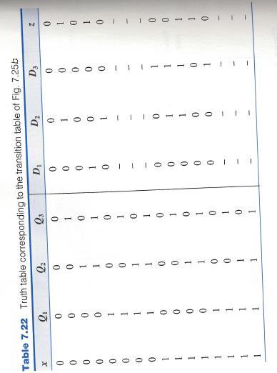
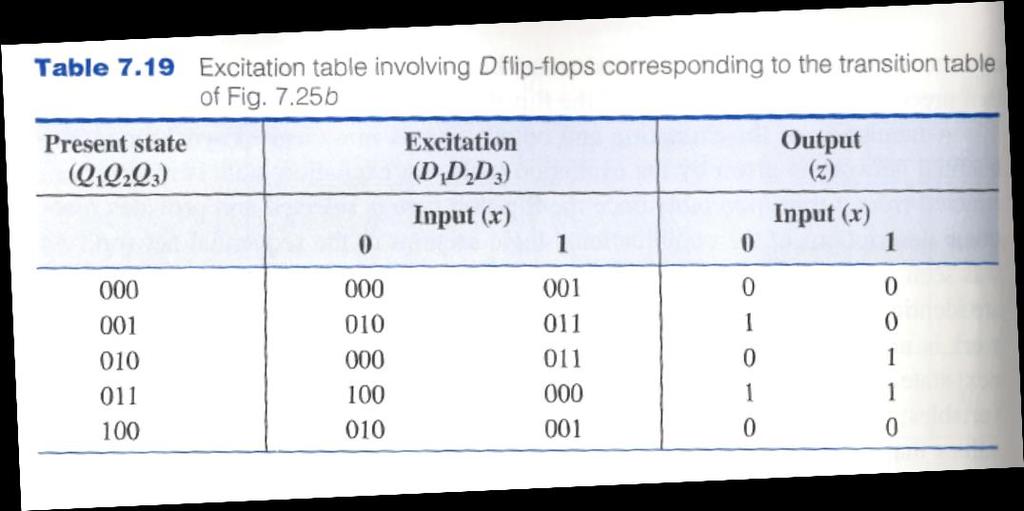
8 PLA Realization D 1 = Q 2 Q 3 x D 2 = Q 2 Q 3 + Q 1 x + Q 2 Q 3 x D 3 = Q 3 x + Q 2 x z = Q 2 x + Q 3 x
9 PLA Realization
10 Final Topic: Algorithmic State Machines Previous chapter dealt with the classical approach to clocked synchronous sequential network design Used models of Mealy and Moore Also called Finite State Machines Algorithmic State Machines (ASM) Different approach to clocked synchronous network design Approach is higher-level Uses flow-charts as in high-level programming We explicitly name and use variables! Capable of handling more complex systems

11 Algorithmic State Machine Partitions the system into two entities: Controller Controlled architecture (data processor) Data processor includes: Flip-flops, shift registers, counters, adders/subtractors, comparators, etc. Controller supplies a time sequence of commands to the devices of the data processer E.g. shift left, shift right, add, subtract, increment, reset. Data processor supplies information about the status of its various devices. The controller is a hardware algorithm (thus is called an algorithmic state machine (ASM).

12 Model of an ASM Mealy Moore


13 ASM Charts Components State Box: The state output list contains output variables that are only a function of the state. Such variables that have logic-1 value are placed in this box. Decision Box

14 Conditional Output Box: ASM Charts Components The conditional output list contains output variables that are a function of the state and external inputs. Such variables that have logic-1 value are placed in this box.

15 ASM Blocks Consists of the interconnection of a single state box along with a collection of decision and conditional output boxes. One entry path, one or more exit paths leading to another state box. A path through an ASM block from its state box to an exit path is called a link path.
16 Rules for ASM blocks For any valid combination of values to the decision-box variables, all simultaneously selected link paths must lead to the same exit path. i.e. next state is uniquely determined There can be no closed loops that do not contain at least one state box State box is the only component that is time dependent.

17 Simple ASM Charts

18 From State Diagram to ASM Chart

19 From State Diagram to ASM Chart
20 Material after this slide is NOT on the Final Exam
21 Examples of ASM Charts
22 A Sequence Recognizer Recognize input sequence of pairs x 1 x 2 = 01,01,11,00 An output z is to be 1 when x 1 x 2 = 00 if and only if the three preceding pairs of inputs are x 1 x 2 = 01,01,11 in that order.

23 A Sequence Recognizer

24 A Parallel Binary Multiplier A C M B Bits of answer are shifted out one at a time
25 A Parallel Binary Multiplier Variables: S = 1 indicates the multiplication is to start M 1 is the multiplier bit appearing at the rightmost end of register M. Z = 1 indicates the content of the counter is 0. INIT = 1 indicates initialization should be performed: 1. Setting flip-flop C and register A to 0 2. Setting counter to the number of bits in the multiplier, N 3. Parallel loading the multiplier and multiplicand into registers M, B. DECREM = 1 enables the counter for decrementing ADD = 1 indicates A and B should be added and resulting N+1 bits entered into register A and flip-flop C SR = 1 indicates the contents of flip-flop C, register A and register M should be shifted one bit position to the right while entering a 0 into flip-flop C. COMPLETE = 1 indicates the multiplication process is complete.

26 A Parallel Binary Multiplier Variables: S = 1 indicates the multiplication is to start M 1 is the multiplier bit appearing at the rightmost end of register M. Z = 1 indicates the content of the counter is 0. INIT = 1 indicates initialization should be performed: 1. Setting flip-flop C and register A to 0 2. Setting counter to the number of bits in the multiplier, N 3. Parallel loading the multiplier and multiplicand into registers M, B. DECREM = 1 enables the counter for decrementing ADD = 1 indicates A and B should be added and resulting N+1 bits entered into register A and flip-flop C SR = 1 indicates the contents of flip-flop C, register A and register M should be shifted one bit position to the right while entering a 0 into flip-flop C. COMPLETE = 1 indicates the multiplication process is complete.
ELCT 501: Digital System Design
 ELCT 5: Digital System Lecture 8: System Dr. Mohamed Abd El Ghany, Algorithmic State Machine (ASM) For large machines, the designers often use a different form of representation, called the algorithmic
Final Exam review: chapter 4 and 5. Supplement 3 and 4
 Final Exam review: chapter 4 and 5. Supplement 3 and 4 1. A new type of synchronous flip-flop has the following characteristic table. Find the corresponding excitation table with don t cares used as much
Microprocessor Design
 Microprocessor Design Principles and Practices With VHDL Enoch O. Hwang Brooks / Cole 2004 To my wife and children Windy, Jonathan and Michelle Contents 1. Designing a Microprocessor... 2 1.1 Overview
UNIVERSITY OF MASSACHUSSETS LOWELL Department of Electrical & Computer Engineering Course Syllabus for Logic Design Fall 2013
 UNIVERSITY OF MASSACHUSSETS LOWELL Department of Electrical & Computer Engineering Course Syllabus for 16.265 Logic Design Fall 2013 I. General Information Section 201 Instructor: Professor Anh Tran Office
Administrative issues. Sequential logic
 Administrative issues Midterm #1 will be given Tuesday, October 29, at 9:30am. The entire class period (75 minutes) will be used. Open book, open notes. DDPP sections: 2.1 2.6, 2.10 2.13, 3.1 3.4, 3.7,
Course Administration
 EE 224: INTRODUCTION TO DIGITAL CIRCUITS & COMPUTER DESIGN Lecture 5: Sequential Logic - 2 Analysis of Clocked Sequential Systems 4/2/2 Avinash Kodi, kodi@ohio.edu Course Administration 2 Hw 2 due on today
Sequencing and Control
 Sequencing and Control Lan-Da Van ( 范倫達 ), Ph. D. Department of Computer Science National Chiao Tung University Taiwan, R.O.C. Spring, 2016 ldvan@cs.nctu.edu.tw http://www.cs.nctu.edu.tw/~ldvan/ Source:
Lecture 11: Synchronous Sequential Logic
 Lecture 11: Synchronous Sequential Logic Syed M. Mahmud, Ph.D ECE Department Wayne State University Aby K George, ECE Department, Wayne State University Contents Characteristic equations Analysis of clocked
Digital Logic Design ENEE x. Lecture 19
 Digital Logic Design ENEE 244-010x Lecture 19 Announcements Homework 8 due on Monday, 11/23. Agenda Last time: Timing Considerations (6.3) Master-Slave Flip-Flops (6.4) This time: Edge-Triggered Flip-Flops
Register Transfer Level in Verilog: Part II
 Source: M. Morris Mano and Michael D. Ciletti, Digital Design, 4rd Edition, 2007, Prentice Hall. Register Transfer Level in Verilog: Part II Lan-Da Van ( 范倫達 ), Ph. D. Department of Computer Science National
Logic and Computer Design Fundamentals. Chapter 7. Registers and Counters
 Logic and Computer Design Fundamentals Chapter 7 Registers and Counters Registers Register a collection of binary storage elements In theory, a register is sequential logic which can be defined by a state
Objectives. Combinational logics Sequential logics Finite state machine Arithmetic circuits Datapath
 Objectives Combinational logics Sequential logics Finite state machine Arithmetic circuits Datapath In the previous chapters we have studied how to develop a specification from a given application, and
Logic Design II (17.342) Spring Lecture Outline
 Spring Lecture Outline") Logic Design II (17.342) Spring 2012 Lecture Outline Class # 05 February 23, 2012 Dohn Bowden 1 Today s Lecture Analysis of Clocked Sequential Circuits Chapter 13 2 Course Admin 3 Administrative Admin
Logic Design II (17.342) Spring 2012 Lecture Outline Class # 05 February 23, 2012 Dohn Bowden 1 Today s Lecture Analysis of Clocked Sequential Circuits Chapter 13 2 Course Admin 3 Administrative Admin
ELCT201: DIGITAL LOGIC DESIGN
 ELCT201: DIGITAL LOGIC DESIGN Dr. Eng. Haitham Omran, haitham.omran@guc.edu.eg Dr. Eng. Wassim Alexan, wassim.joseph@guc.edu.eg Lecture 8 Following the slides of Dr. Ahmed H. Madian محرم 1439 ه Winter
BCN1043. By Dr. Mritha Ramalingam. Faculty of Computer Systems & Software Engineering
 BCN1043 By Dr. Mritha Ramalingam Faculty of Computer Systems & Software Engineering mritha@ump.edu.my http://ocw.ump.edu.my/ authors Dr. Mohd Nizam Mohmad Kahar (mnizam@ump.edu.my) Jamaludin Sallim (jamal@ump.edu.my)
Digital Logic Design I
 Digital Logic Design I Synchronous Sequential Logic Mustafa Kemal Uyguroğlu Sequential Circuits Asynchronous Inputs Combinational Circuit Memory Elements Outputs Synchronous Inputs Combinational Circuit
Digital Fundamentals: A Systems Approach
 Digital Fundamentals: A Systems Approach Counters Chapter 8 A System: Digital Clock Digital Clock: Counter Logic Diagram Digital Clock: Hours Counter & Decoders Finite State Machines Moore machine: One
CprE 281: Digital Logic
 CprE 28: Digital Logic Instructor: Alexander Stoytchev http://www.ece.iastate.edu/~alexs/classes/ Registers and Counters CprE 28: Digital Logic Iowa State University, Ames, IA Copyright Alexander Stoytchev
Chapter 6. Flip-Flops and Simple Flip-Flop Applications
 Chapter 6 Flip-Flops and Simple Flip-Flop Applications Basic bistable element It is a circuit having two stable conditions (states). It can be used to store binary symbols. J. C. Huang, 2004 Digital Logic
Advanced Devices. Registers Counters Multiplexers Decoders Adders. CSC258 Lecture Slides Steve Engels, 2006 Slide 1 of 20
 Advanced Devices Using a combination of gates and flip-flops, we can construct more sophisticated logical devices. These devices, while more complex, are still considered fundamental to basic logic design.
Control Unit. Arturo Díaz-Pérez Departamento de Computación Laboratorio de Tecnologías de Información CINVESTAV-IPN
 Control Unit Arturo Díaz-Pérez Departamento de Computación Laboratorio de Tecnologías de Información CINVESTAV-IPN Large Digital Systems In both combinational and sequential circuit design: small circuits
Figure 30.1a Timing diagram of the divide by 60 minutes/seconds counter
 Digital Clock The timing diagram figure 30.1a shows the time interval t 6 to t 11 and t 19 to t 21. At time interval t 9 the units counter counts to 1001 (9) which is the terminal count of the 74x160 decade
We are here. Assembly Language. Processors Arithmetic Logic Units. Finite State Machines. Circuits Gates. Transistors
 CSC258 Week 5 1 We are here Assembly Language Processors Arithmetic Logic Units Devices Finite State Machines Flip-flops Circuits Gates Transistors 2 Circuits using flip-flops Now that we know about flip-flops
problem maximum score 1 28pts 2 10pts 3 10pts 4 15pts 5 14pts 6 12pts 7 11pts total 100pts
 University of California at Berkeley College of Engineering Department of Electrical Engineering and Computer Sciences EECS150 J. Wawrzynek Spring 2002 4/5/02 Midterm Exam II Name: Solutions ID number:
Previous Lecture Sequential Circuits. Slide Summary of contents covered in this lecture. (Refer Slide Time: 01:55)
") Previous Lecture Sequential Circuits Digital VLSI System Design Prof. S. Srinivasan Department of Electrical Engineering Indian Institute of Technology, Madras Lecture No 7 Sequential Circuit Design Slide
Previous Lecture Sequential Circuits Digital VLSI System Design Prof. S. Srinivasan Department of Electrical Engineering Indian Institute of Technology, Madras Lecture No 7 Sequential Circuit Design Slide
Introduction. Serial In - Serial Out Shift Registers (SISO)
") Introduction Shift registers are a type of sequential logic circuit, mainly for storage of digital data. They are a group of flip-flops connected in a chain so that the output from one flip-flop becomes
Introduction Shift registers are a type of sequential logic circuit, mainly for storage of digital data. They are a group of flip-flops connected in a chain so that the output from one flip-flop becomes
DIGITAL SYSTEM DESIGN UNIT I (2 MARKS)
") DIGITAL SYSTEM DESIGN UNIT I (2 MARKS) 1. Convert Binary number (111101100) 2 to Octal equivalent. 2. Convert Binary (1101100010011011) 2 to Hexadecimal equivalent. 3. Simplify the following Boolean function
DIGITAL SYSTEM DESIGN UNIT I (2 MARKS) 1. Convert Binary number (111101100) 2 to Octal equivalent. 2. Convert Binary (1101100010011011) 2 to Hexadecimal equivalent. 3. Simplify the following Boolean function
Logic Design ( Part 3) Sequential Logic- Finite State Machines (Chapter 3)
 Sequential Logic- Finite State Machines (Chapter 3)") Logic esign ( Part ) Sequential Logic- Finite State Machines (Chapter ) Based on slides McGraw-Hill Additional material 00/00/006 Lewis/Martin Additional material 008 Roth Additional material 00 Taylor
Logic esign ( Part ) Sequential Logic- Finite State Machines (Chapter ) Based on slides McGraw-Hill Additional material 00/00/006 Lewis/Martin Additional material 008 Roth Additional material 00 Taylor
Synchronous sequential circuits
 8.6.5 Synchronous sequential Table of content. Combinational circuit design. Elementary combinatorial for data transmission. Memory structures 4. Programmable logic devices 5. Algorithmic minimization
Logic Design. Flip Flops, Registers and Counters
 Logic Design Flip Flops, Registers and Counters Introduction Combinational circuits: value of each output depends only on the values of inputs Sequential Circuits: values of outputs depend on inputs and
Modeling Digital Systems with Verilog
 Modeling Digital Systems with Verilog Prof. Chien-Nan Liu TEL: 03-4227151 ext:34534 Email: jimmy@ee.ncu.edu.tw 6-1 Composition of Digital Systems Most digital systems can be partitioned into two types
Digital Circuit And Logic Design I. Lecture 8
 Digital Circuit And Logic Design I Lecture 8 Outline Sequential Logic Design Principles (1) 1. Introduction 2. Latch and Flip-flops 3. Clocked Synchronous State-Machine Analysis Panupong Sornkhom, 2005/2
Digital Circuit And Logic Design I
 Digital Circuit And Logic Design I Lecture 8 Outline Sequential Logic Design Principles (1) 1. Introduction 2. Latch and Flip-flops 3. Clocked Synchronous State-Machine Panupong Sornkhom, 2005/2 2 1 Sequential
CPSC 121: Models of Computation Lab #5: Flip-Flops and Frequency Division
 CPSC 121: Models of Computation Lab #5: Flip-Flops and Frequency Division Objectives In this lab, we will see the sequential circuits latches and flip-flops. Latches and flip-flops can be used to build
Latches, Flip-Flops, and Registers. Dr. Ouiem Bchir
 Latches, Flip-Flops, and Registers (Chapter #7) Dr. Ouiem Bchir The slides included herein were taken from the materials accompanying Fundamentals of Logic Design, 6 th Edition, by Roth and Kinney. Sequential
ECSE-323 Digital System Design. Datapath/Controller Lecture #1
 1 ECSE-323 Digital System Design Datapath/Controller Lecture #1 2 Synchronous Digital Systems are often designed in a modular hierarchical fashion. The system consists of modular subsystems, each of which
CSE115: Digital Design Lecture 23: Latches & Flip-Flops
 Faculty of Engineering CSE115: Digital Design Lecture 23: Latches & Flip-Flops Sections 7.1-7.2 Suggested Reading A Generic Digital Processor Building Blocks for Digital Architectures INPUT - OUTPUT Interconnect:
1. a) For the circuit shown in figure 1.1, draw a truth table showing the output Q for all combinations of inputs A, B and C. [4] Figure 1.
![1. a) For the circuit shown in figure 1.1, draw a truth table showing the output Q for all combinations of inputs A, B and C. [4] Figure 1.](/thumbs/88/117492374.jpg "1. a) For the circuit shown in figure 1.1, draw a truth table showing the output Q for all combinations of inputs A, B and C. [4] Figure 1.") [Question 1 is compulsory] 1. a) For the circuit shown in figure 1.1, draw a truth table showing the output Q for all combinations of inputs A, B and C. Figure 1.1 b) Minimize the following Boolean functions:
[Question 1 is compulsory] 1. a) For the circuit shown in figure 1.1, draw a truth table showing the output Q for all combinations of inputs A, B and C. Figure 1.1 b) Minimize the following Boolean functions:
CHAPTER1: Digital Logic Circuits
 CS224: Computer Organization S.KHABET CHAPTER1: Digital Logic Circuits 1 Sequential Circuits Introduction Composed of a combinational circuit to which the memory elements are connected to form a feedback
Sequential Logic. Analysis and Synthesis. Joseph Cavahagh Santa Clara University. r & Francis. TaylonSi Francis Group. , Boca.Raton London New York \
 Sequential Logic Analysis and Synthesis Joseph Cavahagh Santa Clara University r & Francis TaylonSi Francis Group, Boca.Raton London New York \ CRC is an imprint of the Taylor & Francis Group, an informa
Combinational / Sequential Logic
 Digital Circuit Design and Language Combinational / Sequential Logic Chang, Ik Joon Kyunghee University Combinational Logic + The outputs are determined by the present inputs + Consist of input/output
ECE 331 Digital System Design
 ECE 331 Digital System Design Counters (Lecture #20) The slides included herein were taken from the materials accompanying Fundamentals of Logic Design, 6 th Edition, by Roth and Kinney, and were used
ECE 301 Digital Electronics
 ECE 301 Digital Electronics Counters (Lecture #20) The slides included herein were taken from the materials accompanying Fundamentals of Logic Design, 6 th Edition, by Roth and Kinney, and were used with
ECE 341. Lecture # 2
 ECE 341 Lecture # 2 Instructor: Zeshan Chishti zeshan@pdx.edu October 1, 2014 Portland State University Announcements Course website reminder: http://www.ece.pdx.edu/~zeshan/ece341.htm Homework 1: Will
1. Convert the decimal number to binary, octal, and hexadecimal.
 1. Convert the decimal number 435.64 to binary, octal, and hexadecimal. 2. Part A. Convert the circuit below into NAND gates. Insert or remove inverters as necessary. Part B. What is the propagation delay
Analysis of Clocked Sequential Circuits
 Analysis of Clocked Sequential Circuits COE 202 Digital Logic Design Dr. Muhamed Mudawar King Fahd University of Petroleum and Minerals Presentation Outline Analysis of Clocked Sequential circuits State
CSE Latches and Flip-flops Dr. Izadi. NOR gate property: A B Z Cross coupled NOR gates: S M S R Q M
 CSE-4523 Latches and Flip-flops Dr. Izadi NOR gate property: A B Z A B Z Cross coupled NOR gates: S M S R M R S M R S R S R M S S M R R S ' Gate R Gate S R S G R S R (t+) S G R Flip_flops:. S-R flip-flop
CPSC 121: Models of Computation Lab #5: Flip-Flops and Frequency Division
 CPSC 121: Models of Computation Lab #5: Flip-Flops and Frequency Division Objectives In this lab, you will see two types of sequential circuits: latches and flip-flops. Latches and flip-flops can be used
Lecture 12. Amirali Baniasadi
 CENG 24 Digital Design Lecture 2 Amirali Baniasadi amirali@ece.uvic.ca This Lecture Chapter 6: Registers and Counters 2 Registers Sequential circuits are classified based in their function, e.g., registers.
Flip-flop and Registers
 ECE 322 Digital Design with VHDL Flip-flop and Registers Lecture Textbook References n Sequential Logic Review Stephen Brown and Zvonko Vranesic, Fundamentals of Digital Logic with VHDL Design, 2 nd or
Flip-Flops and Sequential Circuit Design
 Flip-Flops and Sequential Circuit Design ECE 52 Summer 29 Reading ssignment Brown and Vranesic 7 Flip-Flops, Registers, Counters and a Simple Processor 7.5 T Flip-Flop 7.5. Configurable Flip-Flops 7.6
COE328 Course Outline. Fall 2007
 COE28 Course Outline Fall 2007 1 Objectives This course covers the basics of digital logic circuits and design. Through the basic understanding of Boolean algebra and number systems it introduces the student
Chapter 3. Boolean Algebra and Digital Logic
 Chapter 3 Boolean Algebra and Digital Logic Chapter 3 Objectives Understand the relationship between Boolean logic and digital computer circuits. Learn how to design simple logic circuits. Understand how
Read-only memory (ROM) Digital logic: ALUs Sequential logic circuits. Don't cares. Bus
 Digital logic: ALUs Sequential logic circuits. Don't cares. Bus") Digital logic: ALUs Sequential logic circuits CS207, Fall 2004 October 11, 13, and 15, 2004 1 Read-only memory (ROM) A form of memory Contents fixed when circuit is created n input lines for 2 n addressable
Digital logic: ALUs Sequential logic circuits CS207, Fall 2004 October 11, 13, and 15, 2004 1 Read-only memory (ROM) A form of memory Contents fixed when circuit is created n input lines for 2 n addressable
Digital Systems Laboratory 1 IE5 / WS 2001
 Digital Systems Laboratory 1 IE5 / WS 2001 university of applied sciences fachhochschule hamburg FACHBEREICH ELEKTROTECHNIK UND INFORMATIK digital and microprocessor systems laboratory In this course you
(CSC-3501) Lecture 7 (07 Feb 2008) Seung-Jong Park (Jay) CSC S.J. Park. Announcement
 Lecture 7 (07 Feb 2008) Seung-Jong Park (Jay) CSC S.J. Park. Announcement") Seung-Jong Park (Jay) http://www.csc.lsu.edu/~sjpark Computer Architecture (CSC-3501) Lecture 7 (07 Feb 2008) 1 Announcement 2 1 Combinational vs. Sequential Logic Combinational Logic Memoryless Outputs
Seung-Jong Park (Jay) http://www.csc.lsu.edu/~sjpark Computer Architecture (CSC-3501) Lecture 7 (07 Feb 2008) 1 Announcement 2 1 Combinational vs. Sequential Logic Combinational Logic Memoryless Outputs
Electrical and Telecommunications Engineering Technology_TCET3122/TC520. NEW YORK CITY COLLEGE OF TECHNOLOGY The City University of New York
 NEW YORK CITY COLLEGE OF TECHNOLOGY The City University of New York DEPARTMENT: SUBJECT CODE AND TITLE: COURSE DESCRIPTION: REQUIRED: Electrical and Telecommunications Engineering Technology TCET 3122/TC
Eng. Mohammed Samara. Fall The Islamic University of Gaza. Faculty of Engineering. Computer Engineering Department
 Fall 2011 The Islamic University of Gaza Faculty of Engineering Computer Engineering Department ECOM 4111 - Digital Systems Design Lab Lab 7: Prepared By: Eng. Mohammed Samara Introduction: A counter is
Finite State Machine Design
 Finite State Machine Design One machine can do the work of fifty ordinary men; no machine can do the work of one extraordinary man. -E. Hubbard Nothing dignifies labor so much as the saving of it. -J.
Chapter Contents. Appendix A: Digital Logic. Some Definitions
 A- Appendix A - Digital Logic A-2 Appendix A - Digital Logic Chapter Contents Principles of Computer Architecture Miles Murdocca and Vincent Heuring Appendix A: Digital Logic A. Introduction A.2 Combinational
Logic Design II (17.342) Spring Lecture Outline
 Spring Lecture Outline") Logic Design II (17.342) Spring 2012 Lecture Outline Class # 03 February 09, 2012 Dohn Bowden 1 Today s Lecture Registers and Counters Chapter 12 2 Course Admin 3 Administrative Admin for tonight Syllabus
Logic Design II (17.342) Spring 2012 Lecture Outline Class # 03 February 09, 2012 Dohn Bowden 1 Today s Lecture Registers and Counters Chapter 12 2 Course Admin 3 Administrative Admin for tonight Syllabus
CS6201 UNIT I PART-A. Develop or build the following Boolean function with NAND gate F(x,y,z)=(1,2,3,5,7).
=(1,2,3,5,7).") VALLIAMMAI ENGINEERING COLLEGE SRM Nagar, Kattankulathur-603203 DEPARTMENT OF COMPUTER SCIENCE AND ENGINEERING Academic Year: 2015-16 BANK - EVEN SEMESTER UNIT I PART-A 1 Find the octal equivalent of hexadecimal
VALLIAMMAI ENGINEERING COLLEGE SRM Nagar, Kattankulathur-603203 DEPARTMENT OF COMPUTER SCIENCE AND ENGINEERING Academic Year: 2015-16 BANK - EVEN SEMESTER UNIT I PART-A 1 Find the octal equivalent of hexadecimal
Computer Organization & Architecture Lecture #5
 Computer Organization & Architecture Lecture #5 Shift Register A shift register is a register in which binary data can be stored and then shifted left or right when a shift signal is applied. Bits shifted
CprE 281: Digital Logic
 CprE 281: igital Logic Instructor: Alexander Stoytchev http://www.ece.iastate.edu/~alexs/classes/ Registers CprE 281: igital Logic Iowa State University, Ames, IA Copyright Alexander Stoytchev Administrative
EECS150 - Digital Design Lecture 3 Synchronous Digital Systems Review. Announcements
 EECS150 - Digital Design Lecture 3 Synchronous Digital Systems Review September 1, 2011 Elad Alon Electrical Engineering and Computer Sciences University of California, Berkeley http://www-inst.eecs.berkeley.edu/~cs150
CprE 281: Digital Logic
 CprE 281: igital Logic Instructor: Alexander Stoytchev http://www.ece.iastate.edu/~alexs/classes/ Registers CprE 281: igital Logic Iowa State University, Ames, IA Copyright Alexander Stoytchev Administrative
Other Flip-Flops. Lecture 27 1
 Other Flip-Flops Other types of flip-flops can be constructed by using the D flip-flop and external logic. Two flip-flops less widely used in the design of digital systems are the JK and T flip-flops.
CSC258: Computer Organization. Combinational Logic
 CSC258: Computer Organization Combinational Logic 1 Anonymous: Quizzes and Fairness... A lot of students in earlier sections share the quiz question with students who have the tutorial later in the evening...
IE1204 Digital Design F11: Programmable Logic, VHDL for Sequential Circuits
 IE1204 Digital Design F11: Programmable Logic, VHDL for Sequential Circuits Elena Dubrova KTH/ICT/ES dubrova@kth.se This lecture BV pp. 98-118, 418-426, 507-519 IE1204 Digital Design, HT14 2 Programmable
Chapter 3 Unit Combinational
 EE 200: Digital Logic Circuit Design Dr Radwan E Abdel-Aal, COE Logic and Computer Design Fundamentals Chapter 3 Unit Combinational 5 Registers Logic and Design Counters Part Implementation Technology
Dr. Shahram Shirani COE2DI4 Midterm Test #2 Nov 19, 2008
 Page 1 Dr. Shahram Shirani COE2DI4 Midterm Test #2 Nov 19, 2008 Instructions: This examination paper includes 13 pages and 20 multiple-choice questions starting on page 3. You are responsible for ensuring
INC 253 Digital and electronics laboratory I
 INC 253 Digital and electronics laboratory I Laboratory 9 Sequential Circuit Author: ID Co-Authors: 1. ID 2. ID 3. ID Experiment Date: Report received Date: Comments For Instructor Full Marks Pre lab 10
VeriLab. An introductory lab for using Verilog in digital design (first draft) VeriLab
 VeriLab") VeriLab An introductory lab for using Verilog in digital design (first draft) VeriLab An introductory lab for using Verilog in digital design Verilog is a hardware description language useful for designing
VeriLab An introductory lab for using Verilog in digital design (first draft) VeriLab An introductory lab for using Verilog in digital design Verilog is a hardware description language useful for designing
1.b. Realize a 5-input NOR function using 2-input NOR gates only.
 . [3 points] Short Questions.a. Prove or disprove that the operators (,XOR) form a complete set. Remember that the operator ( ) is implication such that: A B A B.b. Realize a 5-input NOR function using
Ryerson University Department of Electrical and Computer Engineering EES508 Digital Systems
 1 P a g e Ryerson University Department of Electrical and Computer Engineering EES508 Digital Systems Lab 5 - VHDL for Sequential Circuits: Implementing a customized State Machine 15 Marks ( 2 weeks) Due
 WWW.STUDENTSFOCUS.COM + Class Subject Code Subject Prepared By Lesson Plan for Time: Lesson. No 1.CONTENT LIST: Introduction to Unit III 2. SKILLS ADDRESSED: Listening I year, 02 sem CS6201 Digital Principles
Flip-Flops and Registers
 The slides included herein were taken from the materials accompanying Fundamentals of Logic Design, 6 th Edition, by Roth and Kinney, and were used with permission from Cengage Learning. Flip-Flops and
Experiment 8 Introduction to Latches and Flip-Flops and registers
 Experiment 8 Introduction to Latches and Flip-Flops and registers Introduction: The logic circuits that have been used until now were combinational logic circuits since the output of the device depends
Chapter 5 Synchronous Sequential Logic
 Chapter 5 Synchronous Sequential Logic Chih-Tsun Huang ( 黃稚存 ) http://nthucad.cs.nthu.edu.tw/~cthuang/ Department of Computer Science National Tsing Hua University Outline Introduction Storage Elements:
CprE 281: Digital Logic
 CprE 28: Digital Logic Instructor: Alexander Stoytchev http://www.ece.iastate.edu/~alexs/classes/ Registers and Counters CprE 28: Digital Logic Iowa State University, Ames, IA Copyright Alexander Stoytchev
Digital Principles and Design
 Digital Principles and Design Donald D. Givone University at Buffalo The State University of New York Grauu Boston Burr Ridge, IL Dubuque, IA Madison, Wl New York San Francisco St. Louis Bangkok Bogota
Introduction to Digital Logic Missouri S&T University CPE 2210 Exam 3 Logistics
 Introduction to Digital Logic Missouri S&T University CPE 2210 Exam 3 Logistics Egemen K. Çetinkaya Egemen K. Çetinkaya Department of Electrical & Computer Engineering Missouri University of Science and
Unit 11. Latches and Flip-Flops
 Unit 11 Latches and Flip-Flops 1 Combinational Circuits A combinational circuit consists of logic gates whose outputs, at any time, are determined by combining the values of the inputs. For n input variables,
Flip Flop. S-R Flip Flop. Sequential Circuits. Block diagram. Prepared by:- Anwar Bari
 Sequential Circuits The combinational circuit does not use any memory. Hence the previous state of input does not have any effect on the present state of the circuit. But sequential circuit has memory
Last time, we saw how latches can be used as memory in a circuit
 Flip-Flops Last time, we saw how latches can be used as memory in a circuit Latches introduce new problems: We need to know when to enable a latch We also need to quickly disable a latch In other words,
TMEL53, DIGITALTEKNIK. INTRODUCTION TO SYNCHRONOUS CIRCUITS, FLIP-FLOPS and COUNTERS
 LINKÖPING UNIVERSITY Department of Electrical Engineering TMEL53, DIGITALTEKNIK INTRODUCTION TO SYNCHRONOUS CIRCUITS, FLIP-FLOPS and COUNTERS Mario Garrido Gálvez mario.garrido.galvez@liu.se Linköping,
ELCT201: DIGITAL LOGIC DESIGN
 ELCT201: DIGITAL LOGIC DESIGN Dr. Eng. Haitham Omran, haitham.omran@guc.edu.eg Dr. Eng. Wassim Alexan, wassim.joseph@guc.edu.eg Lecture 7 Following the slides of Dr. Ahmed H. Madian محرم 1439 ه Winter
6.3 Sequential Circuits (plus a few Combinational)
") 6.3 Sequential Circuits (plus a few Combinational) Logic Gates: Fundamental Building Blocks Introduction to Computer Science Robert Sedgewick and Kevin Wayne Copyright 2005 http://www.cs.princeton.edu/introcs
6.3 Sequential Circuits (plus a few Combinational) Logic Gates: Fundamental Building Blocks Introduction to Computer Science Robert Sedgewick and Kevin Wayne Copyright 2005 http://www.cs.princeton.edu/introcs
DIGITAL TECHNICS II. Dr. Bálint Pődör. Óbuda University, Microelectronics and Technology Institute
 26.3.9. DIGITAL TECHNICS II Dr. Bálint Pődör Óbuda University, Microelectronics and Technology Institute 5. LECTURE: ANALYSIS AND SYNTHESIS OF SYNCHRONOUS SEQUENTIAL CIRCUITS 2nd (Spring) term 25/26 5.
 UNIT 1 NUMBER SYSTEMS AND DIGITAL LOGIC FAMILIES 1. Briefly explain the stream lined method of converting binary to decimal number with example. 2. Give the Gray code for the binary number (111) 2. 3.
Universal Asynchronous Receiver- Transmitter (UART)
") Universal Asynchronous Receiver- Transmitter (UART) (UART) Block Diagram Four-Bit Bidirectional Shift Register Shift Register Counters Shift registers can form useful counters by recirculating a pattern
Universal Asynchronous Receiver- Transmitter (UART) (UART) Block Diagram Four-Bit Bidirectional Shift Register Shift Register Counters Shift registers can form useful counters by recirculating a pattern
CMSC 313 Preview Slides
 CMSC 33 Preview Slides These are draft slides. The actual slides presented in lecture may be different due to last minute changes, schedule slippage,... UMBC, CMSC33, Richard Chang CMSC
Good Evening! Welcome!
 University of Florida EEL 3701 Fall 2012 Dr Eric M Schwartz Page 1/11 Exam 2 Instructions: Turn off all cell phones, beepers and other noise making devices Show all work on the front of the test papers
DIGITAL TECHNICS. Dr. Bálint Pődör. Óbuda University, Microelectronics and Technology Institute
 27.2.2. DIGITAL TECHNICS Dr. Bálint Pődör Óbuda University, Microelectronics and Technology Institute 6. LECTURE (ANALYSIS AND SYNTHESIS OF SYNCHRONOUS SEQUENTIAL CIRCUITS) 26/27 6. LECTURE Analysis and
ECE 545 Digital System Design with VHDL Lecture 2. Digital Logic Refresher Part B Sequential Logic Building Blocks
 ECE 545 igital System esign with VHL Lecture 2 igital Logic Refresher Part B Sequential Logic Building Blocks Lecture Roadmap Sequential Logic Sequential Logic Building Blocks Flip-Flops, Latches Registers,
MASSACHUSETTS INSTITUTE OF TECHNOLOGY Department of Electrical Engineering and Computer Sciences
 MASSACHUSETTS INSTITUTE OF TECHNOLOGY Department of Electrical Engineering and Computer Sciences Introductory Digital Systems Lab (6.111) Quiz #2 - Spring 2003 Prof. Anantha Chandrakasan and Prof. Don
IE1204 Digital Design. F11: Programmable Logic, VHDL for Sequential Circuits. Masoumeh (Azin) Ebrahimi
 Ebrahimi") IE1204 Digital Design F11: Programmable Logic, VHDL for Sequential Circuits Masoumeh (Azin) Ebrahimi (masebr@kth.se) Elena Dubrova (dubrova@kth.se) KTH / ICT / ES This lecture BV pp. 98-118, 418-426, 507-519
IE1204 Digital Design F11: Programmable Logic, VHDL for Sequential Circuits Masoumeh (Azin) Ebrahimi (masebr@kth.se) Elena Dubrova (dubrova@kth.se) KTH / ICT / ES This lecture BV pp. 98-118, 418-426, 507-519
ELCT201: DIGITAL LOGIC DESIGN
 ELCT201: DIGITAL LOGIC DESIGN Dr. Eng. Haitham Omran, haitham.omran@guc.edu.eg Dr. Eng. Wassim Alexan, wassim.joseph@guc.edu.eg Lecture 6 Following the slides of Dr. Ahmed H. Madian ذو الحجة 1438 ه Winter
Counter dan Register
 Counter dan Register Introduction Circuits for counting events are frequently used in computers and other digital systems. Since a counter circuit must remember its past states, it has to possess memory.
Spring 2017 EE 3613: Computer Organization Chapter 5: The Processor: Datapath & Control - 1
 Spring 27 EE 363: Computer Organization Chapter 5: The Processor: atapath & Control - Avinash Kodi epartment of Electrical Engineering & Computer Science Ohio University, Athens, Ohio 457 E-mail: kodi@ohio.edu