Communications Signal Analyzer
|
|
|
- Scott Barton
- 6 years ago
- Views:
Transcription
 Automatic ITU/ANSI Mask Testing Normal, Infinite, Variable Persistence and Color Graded Display Modes Intuitive User Interface Large Color Display (10 in.")
1 Features & Benefits Automatic Communication Measurements (RZ and NRZ) Q-factor Extinction Ratio Optical Power Signal-to-Noise Ratio Jitter Wide Bandwidth (DC to 70+ GHz* 1 with up to 12.5 GHz Trigger) Automatic ITU/ANSI Mask Testing Normal, Infinite, Variable Persistence and Color Graded Display Modes Intuitive User Interface Large Color Display (10 in.) MS Windows Operating System Modular Architecture Fast Acquisition Rate Communications Signal Analysis Solutions Specifically designed for high-performance Modularity and Flexibility communications applications, the The supports a large and growing Communications Signal Analyzer is the family of optical and electrical plug-in ideal tool for design evaluation and manufacturing modules. This modular architecture lets test of datacom and telecom you configure the instrument with the right components, transceiver subassemblies features for your application both now and and transmission systems. in the future. The generates measurement The available optical modules provide results, not just raw data, with time and complete optical test solutions for both amplitude histograms, mask testing and telecom (155 Mb/s to 43 Gb/s) and datacom statistical measurements. It provides a (FibreChannel, InfiniBand and Gigabit communications-tailored measurement Ethernet) applications. set that includes jitter, noise, duty cycle, Each optical module includes all of the overshoot, undershoot, extinction ratio, elements necessary for communications Q-factor, mean optical power and amplitude measurements for both RZ and testing, including an optical to electrical converter, an average power monitor, up NRZ signals. to five data rate filters, a full bandwidth In addition, mask testing of SDH/SONET, path and a low-noise electrical sampler. Gigabit Ethernet and other standards In addition, clock recovery is available as simplifies conformance testing. an option for most optical modules. A large, full color display helps you to The electrical plug-ins include a variety of discriminate waveform details. Colorgrading modules with bandwidths up to 70+ GHz of waveform data adds a third and specialized features such as Time dimension, sample density, to your Domain Reflectometry (TDR). High bandwidth signal acquisitions and analyses. probes are also available for constructing a total acquisition and measurement solution. Excellent Signal Fidelity (Jitter <800 fsec RMS Typical) FrameScan Acquisition Mode Isolate Data Dependent Faults Examine Low-power PRBS Signals Eliminate Random Noise and Jitter Via Averaging Windows 2000 for Enhanced Network Security Applications Manufacturing/Testing for ITU/ANSI Conformance Designing/Verification of Telecom and Datacom Elements * 1 Bandwidth is determined by plug-in modules and may exceed 70 GHz should higher speed modules become available in the future. 1
2 2
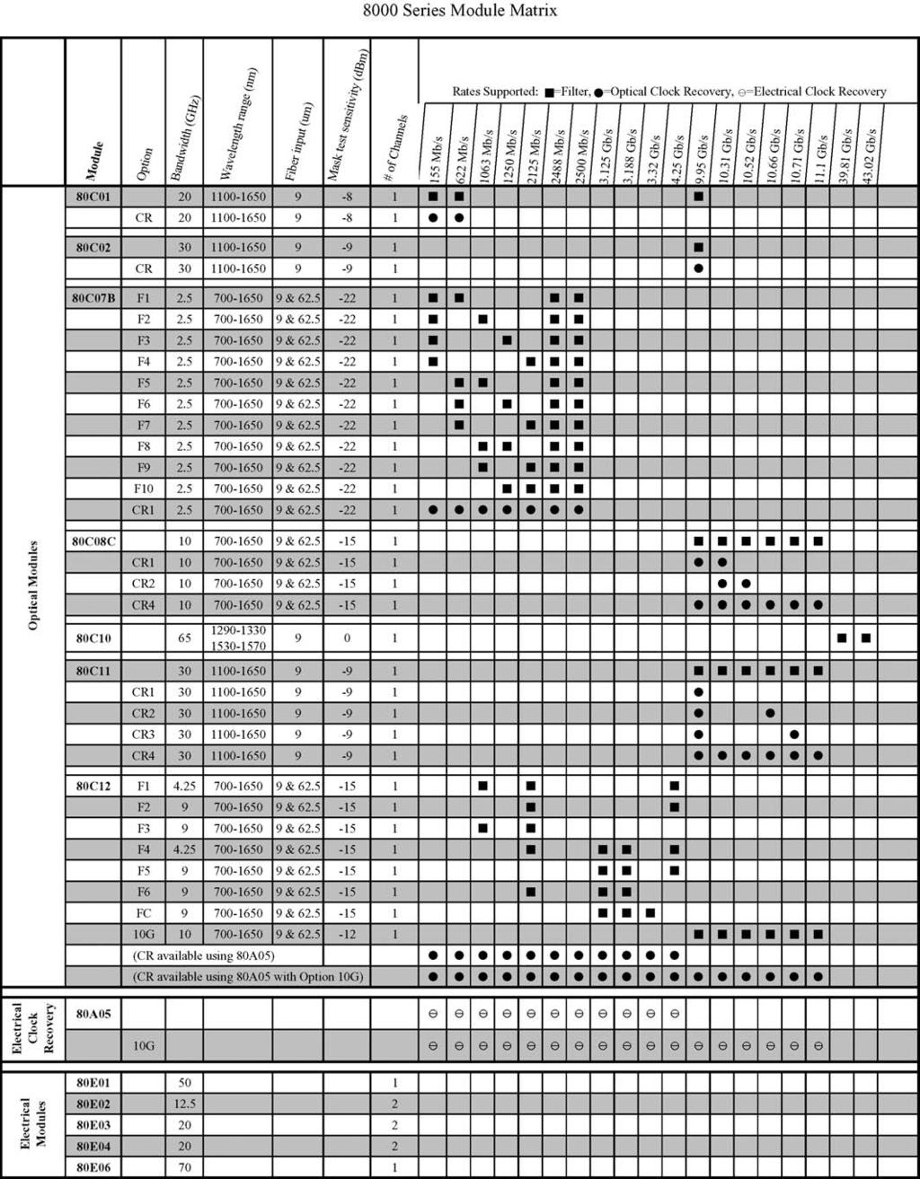
3 Superior Performance With its industry-best horizontal timebase stability, trigger jitter, signal sensitivity and noise performance, the ensures the most accurate acquired signal for high-speed optical communications testing. The s multi-processor architecture, with dedicated per channel digital signal processors (DSP), also provides industry-best waveform acquisition rates that shorten test times. The s FrameScan TM acquisition mode can be used with a variety of BERTs and/or protocol analyzers to isolate pattern dependent effects in transmitters or show the bit sequence leading up to a mask violation. FrameScan acquisition mode also allows averaging of eye diagrams. This can be used to extract a clean eye diagram from noisy low-level signals Series Sampling Oscilloscope Platform The is built on Tektronix sampling oscilloscope platform that combines familiar MS Windows-based PC technologies with world-class waveform acquisition technology. This platform provides a wide array of standard instrumentation and communications interfaces (such as GPIB, Parallel Printer Port, RS-232-C and USB Serial Ports and an Ethernet LAN connection). In addition, the platform includes several mass storage devices (floppy disk, removable hard drive and CD-ROM). Gated triggering, a feature that allows the exclusion of selected time periods from being measured, is offered as an option. Finally, because the system supports an Open Windows environment, new levels of data analysis can be done directly on the instrument using commercially available software packages. Additionally, TekVISA TM, a standard software accessory, allows the instrument to be placed under the control of software applications (e.g., LabView, LabWindows, Visual Basic, Microsoft Excel, C, etc.) running on the instrument, or on external PC workstations network connected to the instrument, without the need for a GPIB hardware interface. Plug and play drivers for LabView and other programs are also supplied Series Sampling Oscilloscope Optical Modules 80C01 Multi-rate Telecom Sampling Module The 80C01 module supports waveform conformance testing of longwavelength (1100 to 1650 nm) signals at 622, 2488 Mb/s and Gb/s as well as general-purpose testing with up to 20 GHz optical bandwidth. With its clock recovery option, the 80C01 provides testing solutions for 622 and 2488 Mb/s telecom applications. 80C02 High-performance Telecom Sampling Module The 80C02 module is optimized for testing of long-wavelength (1100 to 1650 nm) signals at Gb/s (SONET OC-192/SDH STM-64). With its high optical bandwidth of 30 GHz (typical), it is also well-suited for general-purpose highperformance optical component testing. The 80C02 can be optionally configured with clock recovery that supports Gb/s telecom standards. 80C07B Multi-rate, Datacom & Telecom Optical Sampling Module The 80C07B module is a broad wavelength (700 to 1650 nm) multi-rate optical sampling module optimized for testing datacom/telecom signals from 155 to 2500 Mb/s. With its amplified O/E converter design, this module provides excellent signal-to-noise performance, allowing users to examine low-power optical signals. The 80C07B can be optionally configured with clock recovery that supports 155, 622, 1063, 1250, 2125, 2488, 2500 and 2666 Mb/s rates. 80C08C Multi-rate, Datacom & Telecom Optical Sampling Module with 10 GbE Forward Error Correction The 80C08C module is a broad wavelength (700 to 1650 nm) multi-rate optical sampling module providing datacom rate testing for 10GbE applications at 9.953, , Gb/s and 10G FibreChannel applications at Gb/s. The 80C08C also provides telecom rate testing at 9.953, , and Gb/s. With its amplified O/E converter design, this module provides excellent signal-to-noise performance and high optical sensitivity, allowing users to examine low-power level optical signals. The 80C08C can be optionally configured with clock recovery options that can support any standard or user defined rate in the continuous range from 9.8 to 12.6 Gb/s. 80C10 65 GHz 40 Gbps Optical Sampling Module with 43 Gbps ITU-T G.709 Forward Error Correction The 80C10 module provides integrated and selectable reference receiver filtering, enabling conformance testing at either 1310 nm or 1550 nm for Gbps (OC-768/STM-256) and Gbps (43 Gbps ITU-T G.709 FEC) rates. In addition to the filter rates, the user may also choose selectable bandwidths of 30 GHz or 65 GHz for optimal noise vs. bandwidth performance for accurate signal characterization. 80C11 Multi-rate, Datacom & Telecom Optical Sampling Module The 80C11 module is a long wavelength (1100 to 1650 nm) multi-rate optical sampling module optimized for testing 10 Gb/s datacom and telecom standard rates at 9.953, , 3
4 , , , and Gb/s. With its high optical bandwidth of up to 30 GHz (typical) it is well-suited for general purpose high-performance 10 Gb/s optical component testing. The 80C11 can be optionally configured with clock recovery options that can support any standard or user defined rate in the continuous range from 9.8 to 12.6 Gb/s. 80C12 Multi-rate, Datacom & Telecom Optical Sampling Module The 80C012 module is a broad wavelength (700 to 1650 nm) multi-rate optical sampling module providing multi-rate telecom and datacom testing. This highly flexible module can be configured to support either lower data rate applications (1 to 4 Gb/s) or a wide variety of 10Gb/s applications. The low data rate applications include: 1, 2, and 4 Gb/s FibreChannel and by 4 wavelength division multiplex standards such as 10GBase-X4 and 4-Lane 10 Gb/s FibreChannel. The supported 10Gb/s application includes both datacom and telecom application. The supported 10Gb/s datacom applications include 10GbE applications at 9.953, , Gb/s and 10G FibreChannel applications at Gb/s. The 80C12 also provides telecom rate testing at 9.953, , and Gb/s. With its amplified O/E converter design, this module provides excellent signal-to-noise performance and high optical sensitivity, allowing users to examine low-power level optical signals. Clock recovery for the 80C12 is provided via the 80A05 (sold separately) Series Sampling Oscilloscope Electrical Modules 80E01 Sampling Module The 80E01 is a single-channel, 50 GHz bandwidth sampling module. The 80E01 has a measured bandwidth of 50 GHz or more and a calculated rise time of 7.0 ps or less. Displayed noise is typically 1.8 mv RMS. The front-panel connector is female 2.4 mm and an adapter is provided (2.4 mm male to 2.92 mm female) to maintain compatibility with SMA connector systems. 80E02 Low-noise Sampling Module The 80E02 is a dual-channel, 12.5 GHz sampling module specifically designed for low-noise measurements in digital communications and device characterization applications. It provides an acquisition rise time of 28 ps and typically 400 µv RMS of displayed noise. The 80E02 is the ideal instrument for low-noise applications. Common applications for the 80E02 are capturing and displaying switching characteristics of high-speed communications circuits, making accurate statistical measurements of signal noise and signal timing jitter or obtaining stable timing measurements of fast digital ICs. 80E03 Sampling Module The 80E03 is a dual-channel, 20 GHz sampling module. This sampling module provides an acquisition rise time of 17.5 ps. 80E04 TDR Sampling Module The 80E04 is a dual-channel, 20 GHz sampling module with TDR capability. This sampling module provides an acquisition rise time of 17.5 ps, with a typical 20 GHz equivalent bandwidth. The TDR feature provides high resolution with true differential capability and fast 35 ps reflected rise time of the TDR slope. 80E GHz Sampling Module The 80E06 is a single channel, 70+ GHz (typical bandwidth) sampling module with 5.0 ps calculated rise time. Typical RMS noise is 1.8 mv. This sampling module provides a 1.85 mm (Type V) front-panel connector and a precision adapter to 2.92 mm with a 50 Ω SMA termination. 1 meter or 2 meter length Extender Cables can be ordered for remote operation of the sampling module from the sampling oscilloscope mainframe. 80A05 Electrical Clock Recovery Module The 80A05 enables clock recovery for electrical signals, as well as internal triggering on the recovered clock. The module recovers clocks from serial data streams for all of the most common electrical standards in the 50 Mb/s to 4.26 Gb/s range. Option 10G adds support for standard rates up to 12.6 Gb/s. The module accepts either single-ended or differential signals at its input, providing both single-ended and differential clock recovery. This module also serves as the clock recovery module for the 80C12. Characteristics Signal Acquisition Acquisition Modes Sample (normal), envelope and average. Number of Sampling Modules Accommodated Up to four, dual-channel electrical and two, singlechannel optical sampling modules. Number of Simultaneously Acquired Inputs Eight channels maximum (eight electrical or two optical and six electrical). Vertical Systems Rise Time/Bandwidth Determined by the sampling modules used. Vertical Resolution 14 bits over the sampling modules dynamic range. Horizontal System Main and Magnification View Timebases 1ps/div to 5 ms/div in sequence or 1 ps increments. Maximum Trigger Rate 200 khz. Typical Acquisition Rate 150 Ksamples/sec per channel. Time Interval Accuracy Horizontal scale: <21 ps/div: 1 ps + 1% of interval. Horizontal scale: 21 ps/div: 8 ps +0.1% of interval (short-term optimized mode). 8 ps % of interval (locked to 10 MHz mode). Horizontal Deskew Range: 500 ps to +100 ns on any individual channel in 1 ps increments. Record Length 20, 50, 100, 250, 500, 1000, 2000 or 4000 samples. Magnification Views In addition to the main timebase, the supports two magnification views. These magnifications are independently acquired using separate timebase settings which enable higher resolution sampling. 4
5 Trigger System Trigger Sources External direct trigger. External pre-scaled trigger. Internal clock trigger: Internally connected to direct trigger. Clock recovery triggers (from optical sampling modules) internally connected to pre-scaled trigger. Trigger Sensitivity External direct trigger output: 50 mv, DC 4 GHz (typical). 100 mv, DC 3 GHz (guaranteed). Pre-scaled trigger input: 800 mv, 2 to 3 GHz (guaranteed). 600 mv, 3 to 10 GHz (guaranteed) mv, 10 to 12, 5 GHz (typical). Jitter Short-term jitter optimized mode: 0.8 ps RMS +5 ppm (typical). 1.2 ps RMS +10 ppm (max.). Locked to 10 MHz reference: 1.6 ps RMS ppm of position (typical). 2.5 ps RMS ppm of position (max.). Internal Clock Adjustable from 25 to 200 khz (drives TDR, internal clock output and calibrator). Trigger Level Range ±1.0 V. Trigger Input Range ±1.5 V. Trigger Holdoff Adjustable 5 µs to 100 ms in 2 ns increments. External Trigger Gate (optional) TTL logic 1 enables gate, a TTL logic 0 disables gate, maximum non-destruct input level ±5 V. Display Features Touch Screen Display 10.4 in. diagonal, color. Colors 16,777,216 (24 bits). Video Resolution 640 horizontal by 480 vertical displayed pixels. Math/Measurement System Measurements The supports up to eight simultaneous measurements, updated three times per second with optional display of per measurement statistics (min, max, mean and standard deviation). Measurement Set Automated Measurements include RZ, NRZ, and Pulse signal types and the following: Amplitude Measurements: High, Low, Amplitude, Max, Mid, Min, +Width, Eye Height, Eye Opening Factor, Pulse Symmetry, Peak-to-Peak, Pk-Pk, +Overshoot, Overshoot, Mean, +Duty Cycle, Cycle Mean, RMS, Cycle RMS, AC RMS, Gain, Extinction Ratio (Ratio, %, db), Suppression Ratio (Ratio, %, db), Peak to Peak Noise, RMS Noise, Q-Factor, SNR, Average Optical Power, (dbm, watts), Phase, Optical Modulation Amplitude. Timing Measurements: Rise, Fall, Period, Bit Rate, Bit Time, Frequency, Crossing (%, Level, Time), +Cross, Cross, Jitter (pk-pk, RMS), Eye Width, +Width, Width, Burst Width, +Duty Cycle, Duty Cycle, Duty Cycle Distortion, Delay, Phase. Area Measurements: Area, Cycle Area. Cursors Dot, vertical bar and horizontal bar cursors. Waveform Processing Up to eight math waveforms can be defined and displayed using the following math functions: Add, Subtract, Multiply, Divide, Average, Differentiate, Exponentiate, Integrate, Natural Log, Log, Magnitude, Min, Max, Square Root and Filter. In addition, measurement values can be utilized as scalars in math waveform definitions. Mask Testing In addition to user-defined masks, the following predefined masks are built-in: Standard Rate (Gb/s) unless otherwise noted STM-0/OC Mb/s STM-1/OC Mb/s STM-4/OC Mb/s STM-16/OC STM-64/OC STM-256/OC FEC FEC FEC FEC 43 Gb/s G FEC FC-10 G FC Mb/s FC Mb/s FC Mb/s FC FC FC G BASE-X G BASE-W G BASE-R GbE FEC InfiniBand Gigabit Ethernet Power Requirements Line Voltage and Frequency 100 to 240 VAC ±10% 50/60 Hz. 115 VAC ±10% 400 Hz. Environmental Temperature Operating: +10 ºC to +40 ºC. Nonoperating: 22 ºC to +60 ºC. Relative Humidity Operating: Floppy disk and CD-ROM not installed: 20% to 80% at or below 40 ºC (upper limit derates to 45% relative humidity at 40 ºC). Nonoperating: 5% to 90% at or below 60 ºC (upper limit de-rates to 20% relative humidity at +60 ºC). Altitude Operating: 3,048 m (10,000 ft.). Nonoperating: 12,190 m (40,000 ft.). Electromagnetic Compatibility 89/336/EEC. Safety UL3111-1, CSA1010.1, EN , IEC Physical Characteristics for Optical Sampling Modules Dimensions Weight (mm/inches) (kg/lb) Width Height Depth Net 80C01 165/6.5 25/ /12.0 <2.61/< C02 165/6.5 25/ /12.0 <2.61/< C07B 165/6.5 25/ /12.0 <1.36/<3.0 80C08C 165/6.5 25/ /12.0 <1.22/<2.7 80C10 165/6.5 25/ /12.0 >2.61/> C11 165/6.5 25/ /12.0 <1.22/<2.7 80C12 165/6.5 25/ /12.0 <2.61/<5.75 5
6 Optical Sampling Module Characteristics (Refer to Optical Sampling Module User Manual for more detailed information) Application Type Standard and Supported Number of Effective Calibrated Wavelengths Data Filtering Rates Input Channels Wavelength Range 80C01 Tributary Telecom OC-12/STM-4 (622 Mb/s), nm to 1650 nm 1310 nm and 1550 nm (±20 nm) OC-48/STM-16 (2.488 Gb/s), OC-192/STM-64 (9.953 Gb/s) 80C02 10 Gb/s Telecom OC-192/STM-64 (9.953 Gb/s) nm to 1650 nm 1310 nm and 1550 nm (±20 nm) 10GBASE-W (9.953 Gb/s) 80C07B Tributary Standard Included: nm to 1650 nm 780 nm, 850 nm, 1310 nm, Datacom/Telecom OC-48/STM-16 (2.488 Gb/s), and 1550 nm (±20 nm) InfiniBand, 2 GbE (2.500 Gb/s); Optional (choose any two): OC-3/STM-1 (155 Mb/s), OC-12/STM-4 (622 Mb/s), FibreChannel (1.063 Gb/s), GbE (1.250 Gb/s), 2G FibreChannel (2.125 Gb/s) 80C08C 10 Gb/s OC-192/STM-64 (9.953 Gb/s), nm to 1650 nm 780 nm, 850 nm, 1310 nm, Datacom/Telecom 10GBASE-W (9.953 Gb/s), and 1550 nm (±20 nm) 10GBASE-R (10.31 Gb/s), 10G FibreChannel (10.52 Gb/s), ITU-T G.975 FEC ( Gb/s), ITU-T G.709 ( Gb/s), 10 GbE FEC (11.1 Gb/s) 80C10 40 Gb/s Telecom OC-768/STM-256 ( Gb/s), nm and 1550 nm 1310 nm and 1550 nm (±20 nm) ITU-T G.709 FEC ( Gb/s) 80C11 10 Gb/s OC-192/STM-64 (9.953 Gb/s), nm and 1650 nm 1310 nm and 1550 nm (±20 nm) Datacom/Telecom 10GBASE-W (9.953 Gb/s), 10GBASE-R (10.31 Gb/s), 10G FibreChannel (10.52 Gb/s), ITU-T G.975 FEC ( Gb/s), ITU-T G.709 ( Gb/s), 10 GbE FEC (11.1 Gb/s) 80C12 FibreChannel, Option 10G: OC192/STM nm to 1650 nm 850, 1310 and Datacom rates Gb/s 1550 nm (±20 nm) between 2.5 Gb/s 10GBase-W Gb/s and 10 Gb/s 10GBase-R Gb/s Option 10G: 10 Gb/s 10 GFC Gb/s multistandard G.975 FEC Gb/s low cost G.709 FEC Gb/s 10 GbE FEC Gb/s Option F1: Gb/s, Gb/s, and 4.25 Gb/s FC Option F2: Gb/s, 4.25 Gb/s FC, 9 GHz Option F3: Gb/s, Gb/s FC, 9 GHz Option F4: Gb/s, 10GBase-LX4, Gb/s, 4.25 Gb/s FC Option F5: 10GBase-LX4, Gb/s, 4.25 Gb/s FC, 9 GHz Option F6: Gb/s FC, 10GBase-LX4, Gb/s, 9 GHz Option FC: 11GBase-LX4 filter, Gb/s, GHz, 9 GHz 6
7 Optical Sampling Module Characteristics (continued) Clock Recovery Clock Recovery Unfiltered Optical Absolute Maximum Internal Fiber (Optional) Outputs Bandwidth* 1 Nondestructive Diameter Optical Input 80C01 Option CR: 622 Mb/s, ±Clock, ±Data 20 GHz 5 mw average; 9 µm/125 µm single-mode Gb/s 10 mw peak power at wavelength of highest relative responsivity 80C02 Option CR: Gb/s Clock, 28 GHz 5 mw average; 9 µm/125 µm single-mode Clock/16, Data 10 mw peak power at wavelength of highest relative responsivity 80C07B Option CR1: 155 Mb/s, ±Clock, ±Data 2.5 GHz 5 mw average; 62.5 µm/125 µm multi-mode 622 Mb/s, Gb/s, 10 mw peak power at Gb/s, Gb/s, wavelength of Gb/s, Gb/s, highest responsivity Gb/s 80C08C Option CR1: Gb/s, Clock, Clock/16 10 GHz 1 mw average; Single-mode and Gb/s; 10 mw peak power at multi-mode fibers up Option CR2: Gb/s, wavelength of to core diameter Gb/s; highest responsivity of 62.5 µm Option CR4: Continuous from 9.8 Gb/s to 12.6 Gb/s 80C10 Future Upgradeable Future 65 GHz 20 mw average; 9 µm/125 µm single-mode 60 mw peak power at wavelength of highest relative responsivity 80C11 Option CR1: Gb/s; CR1: Clock, Clock/16, Data; 28 GHz 5 mw average; 9 µm/125 µm single-mode Option CR2: Gb/s, CR2, CR3, CR4: 10 mw peak power at Gb/s; Clock, Clock/16 wavelength of Option CR3: Gb/s, highest responsivity Gb/s; Option CR4: Continuous between 9.8 Gb/s to 12.6 Gb/s 80C12 Provided by (Clk/16, 10G Clk) 4 to 10 Gb/s 1 mw average; 10 mw Single-mode and separately sold 80A05 depending peak power at wavelength multi-mode fibers up (50 Mb/s to 12.6 Gb/s) on option of highest responsitivity to core diameter of 62.5 µm * 1 Values shown are warranted unless printed in an italic typeface which represents a typical value. 7
8 Optical Sampling Module Characteristics (continued) Optical Fiber Input RMS Optical Noise RMS Optical Noise Independent Return Loss Accepted (typical) (maximum) Channel Deskew 80C01 >30 db single-mode 8.0 µw at 622 Mb/s, 12.0 µw at 622 Mb/s, Standard Gb/s, Gb/s, Gb/s, Gb/s, 12.5 GHz; 15.0 µw at 20 GHz 12.5 GHz; 25 µw at 20 GHz 80C02 >30 db single-mode 6.0 µw at Gb/s, 10.0 µw at Gb/s, Standard 12.5 GHz; 10.0 µw at 12.5 GHz mode; 15 µw at 20 GHz; 15.0 µw at 30 GHz 20 GHz; 30 µw at 30 GHz 80C07B >14 db (multi-mode) single- or multi-mode 0.50 µw at 155 Mb/s, 1.0 µw at 155 Mb/s, Standard >24 db (single-mode) 622 Mb/s, 1063 Mb/s, 622 Mb/s, 1063 Mb/s, 1250 Mb/s; 0.70 µw at 1250 Mb/s; 2.488/2.500 Gb/s 1.5 µw at 2.488/2.500 Gb/s 80C08C >14 db (multi-mode) >24 db (single-mode) single- or multi-mode 1.7 µw at all filter rates 3.0 µw at all filter rates Standard 80C10 >30 db single-mode 40 µw at Gb/s, 60 µw at Gb/s, Standard Gb/s (1550 nm); Gb/s (1550 nm); 75 µw at Gb/s, 110 µw at Gb/s, Gb/s (1310 nm); Gb/s (1310 nm); 30 µw at 30 GHz mode 50 µw at 30 GHz (1550 nm); 55 µw at (1550 nm); 90 µw at 30 GHz mode (1310 nm); 30 GHz (1310 nm); 85 µw at 65 GHz mode 120 µw at 65 GHz (1550 nm); 150 µw at (1550 nm); 220 µw at 65 GHz mode (1310 nm) 65 GHz (1310 nm) 80C11 >30 db single-mode 5.5 µw at all filter rates; 8.0 µw at all filter rates; Standard 10.0 µw at 20 GHz 14.0 µw at 20 GHz 20.0 µw at 30 GHz 30.0 µw at 30 GHz 80C12 >14 db single- or multi-mode Below 9 Gb/s: 1.7 µw Below 9 Gb/s: 3 µw Standard (62.5 µm multi-mode) Above 9 Gb/s and 9 GHz: 3.4 µw Above 9 Gb/s and 9 GHz: 6 µw >24 db (9 µm single mode) Offset Power Power Power Meter Mask Test Capability Meter Meter Range Accuracy Optical Sensitivity* 2 80C01 Standard Standard +4 dbm to 30 dbm 5% of reading 8 dbm at 622 Mb/s, Gb/s, Gb/s; 5.0 dbm at 20 GHz 80C02 Standard Standard +4 dbm to 30 dbm 5% of reading 9 dbm at Gb/s; 7 dbm at 20 GHz; 4 dbm at 30 GHz 80C07B Standard Standard +4 dbm to 30 dbm 5% of reading 22 dbm at 155 Mb/s, 622 Mb/s; 20 dbm at 2488/2500 Mb/s 80C08C Standard Standard 0 dbm to 30 dbm 5% of reading 15 dbm at all filter rates 80C10 Standard Standard +13 dbm to 21 dbm 5% of reading 0 dbm at Gb/s, Gb/s; 0 dbm at 30 GHz; +3 dbm at 65 GHz 80C11 Standard Standard +4 dbm to 30 dbm 5% of reading 10 dbm at all filter rates; 7 dbm at 20 GHz; 4 dbm at 30 GHz 80C12 Standard Standard 0 dbm to 30 dbm 5% of reading Below 9 Gb/s: 15 dbm Above 9 Gb/s and 9 GHz: 12 dbm * 2 Smallest power level for mask test. Values represent theoretical typical sensitivity of NRZ eyes for competitive comparison purposes. Assumes instrument peak-peak noise consumes most of the mask margin. 8
9 Physical Characteristics for Electrical Sampling Modules Dimensions (mm/inches) Weight (kg/lb) Width Height Depth Net 80E01 79/3.1 25/ / / E02 79/3.1 25/ / / E03 79/3.1 25/ / / E04 79/3.1 25/ / / E06 79/3.1 25/ / /0.87 Electrical Sampling Module Characteristics (Refer to Electrical Sampling Module User Manual for more detailed information) Application Type Channels Input Impedance Channel Input Bandwidth* 3 Connector 80E01 Microwave 1 50 ±0.5 Ω 2.4 mm female Precision 50 GHz General Purpose adapter to 2.92 mm included with 50 Ω SMA termination 80E02 Low-level Signals 2 50 ±0.5 Ω 3.5 mm female 12.5 GHz* 4 80E03 Device Characterization 2 50 ±0.5 Ω 3.5 mm female 20 GHz* 4 80E04 TDR Impedance Characterization 2 50 ±0.5 Ω 3.5 mm female 20 GHz* 4 with single-ended, common, differential TDR capability 80E06 High-speed Electrical 1 50 ±0.5 Ω 1.85 mm female Precision 70+ GHz Device Characterization adapter to 2.92 mm included with 50 Ω SMA termination * 3 Values shown are warranted unless printed in an italic typeface which represents a non-warranted characteristic value that the instrument will typically perform to. * 4 Rise time is calculated from the formula Rise time = 0.35/Bandwidth; bandwidth is calculated from the formula Bandwidth = 0.35/Rise time. Electrical Sampling Module Characteristics (continued) Rise Time Maximum Input Vertical Number (10% to 90%) Dynamic Range Offset Range Voltage of Digitized Bits 80E01 7 ps* V p-p ±1.6 V ±2.0 V 14 bits full scale 80E02 28 ps 1.0 V p-p ±1.6 V ±3.0 V 14 bits full scale 80E ps 1.0 V p-p ±1.6 V ±3.0 V 14 bits full scale 80E ps 1.0 V p-p ±1.6 V ±3.0 V 14 bits full scale 80E ps* V p-p ±1.6 V ±2.0 V 14 bits full scale * 4 Rise time is calculated from the formula Rise time = 0.35/Bandwidth; bandwidth is calculated from the formula Bandwidth = 0.35/Rise time. 9
10 Electrical Sampling Module Characteristics (continued) Vertical Sensitivity DC Vertical Voltage Typical Step Response Aberrations* 5 RMS Noise* 5 Range Accuracy, Single Point, Within ±2 ºC of Compensated Temperature 80E01 10 mv to 1.0 V ± [2 mv (Offset) + ±3% or less over the zone 10 ns to 20 ps before step transition; 1.8 mv 2.3 mv full scale 0.02 (Vertical Value Offset)] +12%, 5% or less for the first 300 ps following step transition; (maximum) +5.5%, 3% or less over the zone 300 ps to 3 ns following step transition; ±1% or less over the zone 3 ns to 100 ns following step transition; ±0.5% after 100 ns following step transition 80E02 10 mv to 1.0 V ± [2 mv (Offset) + ±3% or less over the zone 10 ns to 20 ps before step transition; 400 µv 800 µv full scale 0.02 (Vertical Value Offset)] +10%, 5% or less for the first 300 ps following step transition; (maximum) ±3% or less over the zone 300 ps to 5 ns following step transition; ±1% or less over the zone 5 ns to 100 ns following step transition; ±0.5% after 100 ns following step transition 80E03 10 mv to 1.0 V ± [2 mv (Offset) + ±3% or less over the zone 10 ns to 20 ps before step transition; 600 µv 1.2 mv full scale 0.02 (Vertical Value Offset)] +10%, 5% or less for the first 300 ps following step transition; (maximum) ±3% or less over the zone 300 ps to 5 ns following step transition; ±1% or less over the zone 5 ns to 100 ns following step transition; ±0.5% after 100 ns following step transition 80E04 10 mv to 1.0 V ± [2 mv (Offset) + ±3% or less over the zone 10 ns to 20 ps before step transition; 600 µv 1.2 mv full scale 0.02 (Vertical Value Offset)] +10%, 5% or less for the first 300 ps following step transition; (maximum) ±3% or less over the zone 300 ps to 5 ns following step transition; ±1% or less over the zone 5 ns to 100 ns following step transition; 0.5% after 100 ns following step transition 80E06 10 mv to 1.0 V ± [2 mv (Offset) + ±5% or less for first 300 ps following step transition 1.8 mv 2.4 mv full scale 0.02 (Vertical Value Offset)] (maximum) * 5 Values shown are warranted unless printed in an italic typeface which represents a non-warranted characteristic value that the instrument will typically perform to. TDR System (80E04 only) 80E04* 6 Channels 2 Input Impedance Channel Input Connector Bandwidth TDR Step Amplitude TDR System Reflected Rise Time TDR System Incident Rise Time TDR Step Maximum Repetition Rate TDR System Step Response Aberrations 50 ±0.5 Ω 3.5 mm 20 GHz 250 mv (polarity of either step may be inverted) 35 ps each polarity 28 ps (typical) 200 khz ±3% or less over the zone 10 ns to 20 ps before step transition; +10%, 5% or less typical for the first 400 ps following step transition; ±3% or less over the zone 400 ps to 5 ns following step transition; ±1% or less after 5 ns following step transition * 6 Values shown are warranted unless printed in an italic typeface which represents a non-warranted characteristic value that the instrument will typically perform to. 10
11 Ordering Information Communications Signal Analyzer Includes: User manual, quick reference card, MS Windows 2000 compatible keyboard, MS Windows 2000 compatible mouse, touch screen stylus, online help, programmer online guide, power cord. With OpenChoice TM software, Tektronix provides enhanced test and measurement analysis with the capability of full integration of third-party software on the Open Windows oscilloscopes. By working with the industry leaders, National Instruments and The MathWorks, examples of software programs from these companies are featured on all Tektronix Open Windows oscilloscopes. Options Option C3 Three years of Calibration Service. Option D1 Calibration data report. Option D3 Three years of Calibration data reports. Option GT Gated Trigger. Option R3 Extended repair warranty to three years. Option 1K Cart. Option 1R Rackmount kit (includes: hardware, tooling and instructions for converting bench model to rackmount configuration). International Power Plug Options Option A0 North America power. Option A1 Universal EURO power. Option A2 United Kingdom power. Option A3 Australia power. Option A4 240 V, North America power. Option A5 Switzerland power. Option A99 No power cord or AC adapter. Option AC China power. Other Accessories Calibration Step Generator with Power Cords Std, US: A1, Europe: A2, UK: A3, Australia: A4, North America: A5, Switzerland: A6, Japan: A02 TDS/CSA8000 Series EOS/ESD Protection Module (1 channel). Sampling Module Extender Cable (1 meter) Order Sampling Module Extender Cable (2 meter) Order X Attenuator (SMA male-to-female) Order X Attenuator (male-to-female) Order Adapter (2.4 mm male to 2.92 mm female) Order Power Divider Order Rackmount Kit Order P GHz Single-ended TDR Probe. P GHz Active Probe. P GHz Active FET Probe. P GHz Passive Probe. 80A01 Pre-scaled Trigger Amplifier: The 80A01 Pre-scaled Trigger Amplifier provides enhanced triggering capability on low-level signals up to 12.5 Gb/s. This module plugs into any of the four available electrical sampling module slots on the TDS8000B and the mainframes. It is ideally suited for component designers and manufacturers who are verifying the performance of optical and electrical components that run at nonstandard clock rates up to 12.5 GHz. 80A03 TekConnect TM Probe Interface Module. The 80A03 TekConnect Probe Interface Module provides an interface to Tektronix P7000 series high-performance active and differential probes with 3 GHz bandwidths and higher. The 80A03 accepts up to two P7000 series probes and one electrical sampling module. It plugs into any of the four available electrical sampling module slots on the TDS8000B and mainframes. The 80A03 and P7000 series probes are ideally suited for probing directly on IC pins, traces, or test points that are not accessible through a connector. K4000 Mobile Workstation. 11
12 Contact Tektronix: ASEAN / Australasia / Pakistan (65) Austria Belgium +32 (2) Brazil & South America 55 (11) Canada 1 (800) Central Europe & Greece Denmark Finland +358 (9) France & North Africa +33 (0) Germany +49 (221) Hong Kong (852) India (91) Italy +39 (02) Japan 81 (3) Mexico, Central America & Caribbean 52 (55) The Netherlands +31 (0) Norway People s Republic of China 86 (10) Poland +48 (0) Republic of Korea 82 (2) Russia, CIS & The Baltics +358 (9) South Africa Spain +34 (91) Sweden /4 Taiwan 886 (2) United Kingdom & Eire +44 (0) USA 1 (800) USA (Export Sales) 1 (503) For other areas contact Tektronix, Inc. at: 1 (503) Updated 23 December 2003 Our most up-to-date product information is available at: Product(s) are manufactured in ISO registered facilities. Copyright 2004, Tektronix, Inc. All rights reserved. Tektronix products are covered by U.S. and foreign patents, issued and pending. Information in this publication supersedes that in all previously published material. Specification and price change privileges reserved. TEKTRONIX and TEK are registered trademarks of Tektronix, Inc. All other trade names referenced are the service marks, trademarks or registered trademarks of their respective companies. 01/04 HB/WWW 85W
Digital Sampling Oscilloscope
 Features & Benefits DC to 70+ GHz Bandwidth* 1 Exceptional Trigger Jitter and Horizontal Timebase Stability Modular Architecture Up to Eight Channels Acquisition High Resolution and Measurement Repeatability
Optical Sampling Modules 80C01 80C02 80C07B 80C08C 80C10 80C11 80C12
 Features & Benefits 10 Gb/sTelecom & Datacom 80C08C and 80C12 Lownoise, High Optical Sensitivity and Broad Wavelength Conformance Testing for 10GbE LAN, WAN, and FEC, 10G Fibre Channel, and 10 Gb/s Telecom
Optical Sampling Modules 80C02 80C07B 80C08C 80C10 80C10B 80C11 80C12
 Features & Benefits DSA8200 *2 Series Sampling Oscilloscope Optical Modules The DSA8200 Series Sampling Oscilloscope, when configured with one or more optical sampling modules, provide complete optical
Electrical Sampling Modules Datasheet 80E11 80E11X1 80E10B 80E09B 80E08B 80E07B 80E04 80E03 80E03-NV
 Electrical Sampling Modules Datasheet 80E11 80E11X1 80E10B 80E09B 80E08B 80E07B 80E04 80E03 80E03-NV The DSA8300 Series Sampling Oscilloscope, when configured with one or more electrical sampling modules,
Electrical Sampling Modules
 Electrical Sampling Modules 80E11 80E11X1 80E10B 80E09B 80E08B 80E07B 80E04 80E03 80E03-NV Datasheet Applications Impedance Characterization and S-parameter Measurements for Serial Data Applications Advanced
Data Pattern Generator
 Features & Benefits Data Rate to 1.1 Gb/s Tests High-speed Logic Devices and Circuits Data Pattern Depth to 256 K/Channel Speeds Characterization Multiple Output Channels Increases Flexibility DG2040:
80C00 Optical Modules for DSA8300 Sampling Oscilloscope Datasheet
 80C00 Optical Modules for DSA8300 Sampling Oscilloscope Datasheet Key features The Tektronix 80C00 optical sampling modules, when installed in DSA8300 Digital Serial Analyzer sampling oscilloscopes 1,
40 Gb/s PatternPro Programmable Pattern Generator PPG4001 Datasheet
 40 Gb/s PatternPro Programmable Pattern Generator PPG4001 Datasheet Applications Semiconductor device testing Optical component testing Transceiver module testing The Tektronix PPG4001 PatternPro programmable
40 Gb/s PatternPro Programmable Pattern Generator PPG4001 Datasheet
 40 Gb/s PatternPro Programmable Pattern Generator PPG4001 Datasheet The Tektronix PPG4001 PatternPro programmable pattern generator provides stressed pattern generation for high-speed Datacom testing.
SignalCorrect Software and TCS70902 Calibration Source Option SC SignalCorrect software
 SignalCorrect Software and TCS70902 Calibration Source Option SC SignalCorrect software Eye of signal after de-embed using SignalCorrect Features and benefits Measurement and de-embed: Characterize cables
Optical Modules for DSA8300* 1 Sampling Oscilloscope
 Optical Modules for DSA8300* 1 Sampling Oscilloscope 80C07B, 80C08C, 80C10B, 80C11, 80C12, 80C14, 80C25GBE Data Sheet Features & Benefits 10 Gb/s Telecom and Datacom Highly Accurate ER Calibrated (Extinction
46 GBaud Multi-Format Optical Transmitter
 46 GBaud Multi-Format Optical Transmitter OM5110 Datasheet Applications Testing coherent optical receivers Golden reference coherent optical transmitter Transmitter for multi-carrier superchannel systems
WAVEEXPERT SERIES OSCILLOSCOPES WE 9000 NRO 9000 SDA 100G. The World s Fastest Oscilloscope
 WAVEEXPERT SERIES OSCILLOSCOPES WE 9000 NRO 9000 SDA 100G The World s Fastest Oscilloscope The Fastest Oscilloscope in the Marketplace The WaveExpert and SDA 100G are the first instruments to combine the
Analyzing 8b/10b Encoded Signals with a Real-time Oscilloscope Real-time triggering up to 6.25 Gb/s on 8b/10b encoded data streams
 Presented by TestEquity - www.testequity.com Analyzing 8b/10b Encoded Signals with a Real-time Oscilloscope Real-time triggering up to 6.25 Gb/s on 8b/10b encoded data streams Application Note Application
PatternPro Error Detector PED3200 and PED4000 Series Datasheet
 PatternPro Error Detector PED3200 and PED4000 Series Datasheet Auto-synchronization to input pattern The PED3200 and PED4000 series programmable error detectors offer effective multi-channel BER for stressed
N1000A DCA-X. Wide Bandwidth Oscilloscope Mainframe and Modules. Find us at Page 1
 N1000A DCA-X Wide Bandwidth Oscilloscope Mainframe and Modules Find us at www.keysight.com Page 1 Table of Contents Introduction... 3 N1000A DCA-X Specifications... 4 Module Selection Guide... 12 Module
Network Line Card Testing using the TDS3000B DPO Application Note. Line Card Testing Example: Throughput = Shippable Dollars
 Testing Example: Throughput = Shippable Dollars Overall manufacturing test throughput is dependent on many factors. Figure 1 shows a typical line card test setup using an oscilloscope, a channel multiplexer,
PicoScope 9200A PC Sampling Oscilloscopes for Windows PCs
 PicoScope 9200A PC Sampling Oscilloscopes for Windows PCs Pre-compliance testing Electrical TDR and TDT Production pass/fail testing Complete sampling oscilloscopes for your PC 12 GHz bandwidth on 2 channels
Arbitrary Waveform Generators AWGSYNC01 Synchronization Hub Datasheet
 Arbitrary Waveform Generators AWGSYNC01 Synchronization Hub Datasheet The AWGSYNC01 enables the multi-instrument synchronization of up to four AWG70001A or AWG70002A units allowing up to eight channels
PicoScope 9200A PC Sampling Oscilloscopes for Windows PCs
 PicoScope 9200A PC Sampling Oscilloscopes for Windows PCs Signal characterization Pre-compliance testing Electrical TDR and TDT Production pass/fail testing Complete sampling oscilloscopes for your PC
Data Pattern Generator DG2020A Data Sheet
 Data Pattern Generator DG2020A Data Sheet Applications Low Jitter for Clock Substitution Characterize Device Timing Simulate Missing Functions in System or Subsystem Evaluation Create Complex Data Patterns
PicoScope 9200A PC Sampling Oscilloscopes for Windows PCs
 PicoScope 9200A PC Sampling Oscilloscopes for Windows PCs Signal characterization Pre-compliance testing Electrical TDR and TDT Production pass/fail testing Complete sampling oscilloscopes for your PC
Limit and Mask Test Application Module
 Limit and Mask Test Application Module DPO4LMT Datasheet Features & Benefits Conduct Limit Test Pass/Fail Testing against a Golden Waveform with Tolerances Perform Mask Testing on ITU-T, ANSI T1.102, and
Automatic Changeover Unit ECO8000 Datasheet
 Automatic Changeover Unit ECO8000 Datasheet The ECO8000 is a highly versatile automatic sync and signal changeover unit with configurations and capabilities required to address modern master sync application
Tektronix Video Signal Generators
 Tektronix Video Signal Generators SPG600 and SPG300 Data Sheet The Sync signal generator family SPG600 (full rack width) and SPG300 (half rack width). Features & Benefits Two models, SPG600 (full rack
Video Reference Timing with Tektronix Signal Generators
 Using Stay GenLock Video Reference Timing with Tektronix Signal Generators Technical Brief Digital video systems require synchronization and test signal sources with low jitter and high stability. The
Complete sampling oscilloscope for your PC
 PicoScope 9200 Series PC SAMPLING OSCILLOSCOPES Complete sampling oscilloscope for your PC 12 GHz bandwidth on 2 channels Dual timebase from 10 ps/div Up to 10 GHz trigger bandwidth Optical and electrical
PicoScope 9200 Series
 PicoScope 9200 Series PC SAMPLING OSCILLOSCOPES Complete sampling oscilloscope for your PC 12 GHz bandwidth on 2 channels Dual timebase from 10 ps/div Up to 10 GHz trigger bandwidth Optical and electrical
Automatic Changeover Unit ECO8020 Datasheet
 Automatic Changeover Unit ECO8020 Datasheet The ECO8020 is a highly versatile automatic sync and signal changeover unit with configurations and capabilities required to address modern master sync application
Video Quality Monitors Sentry Edge II Datasheet
 Video Quality Monitors Sentry Edge II Datasheet Remote management of RF measurement collection Proactively detect RF issues before they impact subscribers Full range of Transport Stream monitoring capabilities
Data Pattern Generator DG2020A Data Sheet
 Data Pattern Generator DG2020A Data Sheet DG2000 Series Features & Benefits Data Rate to 200 Mb/s Data Pattern Depth 64 K/channel Speeds Characterization Multiple Output Channels Increases Flexibility
Complete sampling oscilloscope for your PC
 Distribution in the UK & Ireland Characterisation, Measurement & Analysis Lambda Photometrics Limited Lambda House Batford Mill Harpenden Herts AL5 5BZ United Kingdom E: info@lambdaphoto.co.uk W: www.lambdaphoto.co.uk
Agilent N4876A 28 Gb/s Multiplexer 2:1
 Agilent N4876A 28 Gb/s Multiplexer 2:1 Data Sheet Revision 1.0 Features and Benefits Variable data rate up to 28.4 Gb/s Multiplexes two generator channels Front-end box for J-BERT or ParBERT Control via
Agilent N4876A 28 Gb/s Multiplexer 2:1
 Agilent N4876A 28 Gb/s Multiplexer 2:1 Data Sheet, Revision 1.1 Features and Benefits Variable data rate up to 28.4 Gb/s Multiplexes two generator channels Front-end box for J-BERT or ParBERT Control via
Automated Limit Testing
 Automated Limit Testing Limit Testing with Tektronix DPO4000 and MSO4000 Series Oscilloscopes and National Instruments LabVIEW SignalExpress TE for Windows TM Introduction Automated limit testing allows
PicoScope 9300 Series migration guide
 sampling oscilloscopes since 2009 The 9300 Series is a leading-edge product family resulting from a long program of product development. From late 2017, in the process of adding new 15 GHz and 25 GHz models,
Identifying Setup and Hold Violations with a Mixed Signal Oscilloscope APPLICATION NOTE
 Identifying Setup and Hold Violations with a Mixed Signal Oscilloscope Introduction Timing relationships between signals are critical to reliable operation of digital designs. With synchronous designs,
PicoScope 6407 Digitizer
 YE AR PicoScope 6407 Digitizer HIGH PERFORMANCE USB DIGITIZER Programmable and Powerful 1 GHz bandwidth 1 GS buffer size 5 GS/s real-time sampling Advanced digital triggers Built-in function generator
Debugging Memory Interfaces using Visual Trigger on Tektronix Oscilloscopes
 Debugging Memory Interfaces using Visual Trigger on Tektronix Oscilloscopes Application Note What you will learn: This document focuses on how Visual Triggering, Pinpoint Triggering, and Advanced Search
Quick Signal Integrity Troubleshooting with Integrated Logic Analyzers & Oscilloscopes
 Application Overview Quick Signal Integrity Troubleshooting with Integrated Logic Analyzers & Oscilloscopes Meeting Fast Edge Signal Integrity Challenges Fast product development requires fast and efficient
Logic Analyzer Triggering Techniques to Capture Elusive Problems
 Logic Analyzer Triggering Techniques to Capture Elusive Problems Efficient Solutions to Elusive Problems For digital designers who need to verify and debug their product designs, logic analyzers provide
Model 7330 Signal Source Analyzer Dedicated Phase Noise Test System V1.02
 Model 7330 Signal Source Analyzer Dedicated Phase Noise Test System V1.02 A fully integrated high-performance cross-correlation signal source analyzer from 5 MHz to 33+ GHz Key Features Complete broadband
PicoScope 6407 Digitizer
 YE AR HIGH PERFORMANCE USB DIGITIZER Programmable and Powerful 1 GHz bandwidth 1 GS buffer size 5 GS/s real-time sampling Advanced digital triggers Built-in function generator USB-connected Signals Analysis
PicoScope 9200 Series
 PicoScope 9200 Series PC SAMPLING OSCILLOSCOPES Complete sampling oscilloscope for your PC 12 GHz bandwidth on 2 channels Dual timebase from 10 ps/div Up to 10 GHz trigger bandwidth Optical and electrical
Keysight Technologies N4974A PRBS Generator 44 Gb/s. Data Sheet
 Keysight Technologies N4974A PRBS Generator 44 Gb/s Data Sheet Description The Keysight Technologies, Inc. N4974A PRBS generator 44 Gb/s is a self-contained pattern generator capable of operating at either
100G and 400G Datacom Transmitter Measurements
 100G and 400G Datacom Transmitter Measurements Determining Proper Measurement Tools for 100G/400G Datacom Testing The datacom market is an exciting place to be these days, driven in no small part by relentless
Synthesized Clock Generator
 Synthesized Clock Generator CG635 DC to 2.05 GHz low-jitter clock generator Clocks from DC to 2.05 GHz Random jitter
Agilent 86120B, 86120C, 86122B Multi-Wavelength Meters. Data Sheet
 Agilent 86120B, 86120C, 86122B Multi-Wavelength Meters Data Sheet Agilent multi-wavelength meters are Michelson interferometer-based instruments that measure wavelength and optical power of laser light
Advanced Test Equipment Rentals ATEC (2832)
") Established 1981 Advanced Test Equipment Rentals www.atecorp.com 800-404-ATEC (2832) Digital Serial Analyzer Sampling Oscilloscope Industry s best standard timebase jitter performance, 800 fs RMS Industry
Established 1981 Advanced Test Equipment Rentals www.atecorp.com 800-404-ATEC (2832) Digital Serial Analyzer Sampling Oscilloscope Industry s best standard timebase jitter performance, 800 fs RMS Industry
Data Pattern Generator
 Data Pattern Generator DG2040 * DG2030 * DG2020A * P3410/P3420 Characteristics DG2040. Features Specs Ordering Information Pricing Information Print Data Sheet (61kB) Request a Quote Output Data Data Rate
Dual Scope Synchronization
 Dual Scope Synchronization Application Note Introduction The Tektronix DPO/DSA/MSO70000 models above 12GHz in bandwidth provide 50 GS/s sampling rate on each of 4 channels simultaneously, or 100 GS/s sampling
20 GHz bandwidth 17.5 ps rise time
 PicoScope 9300 Series THE NEW FACE OF SAMPLING OSCILLOSCOPES 20 GHz bandwidth 17.5 ps rise time A LONG LIST OF FEATURES 1 MS/s sequential sampling - the industry s fastest NRZ and RZ eye plots and measurements
C-PHY Essentials Transmitter Test Solution TekExpress C-PHY Essentials Tx
 C-PHY Essentials Transmitter Test Solution TekExpress C-PHY Essentials Tx Applications Camera CMOS Image sensors Display Driver ICs Application processor for Mobile devices Tektronix C-PHY TX Essentials
Reference. TDS7000 Series Digital Phosphor Oscilloscopes
 Reference TDS7000 Series Digital Phosphor Oscilloscopes 07-070-00 0707000 To Use the Front Panel You can use the dedicated, front-panel knobs and buttons to do the most common operations. Turn INTENSITY
Digital Serial Analyzer Sampling Oscilloscope
 Digital Serial Analyzer Sampling Oscilloscope DSA8200 Data Sheet Features & Benefits State-of-the-Art Sampling Oscilloscope for Communication Signal Analysis, TDR / TDT / Serial Data Network Analysis,
Tektronix Logic Analyzer Probes P6900 Series Datasheet for DDR Memory Applications
 Tektronix Logic Analyzer Probes P6900 Series Datasheet for DDR Memory Applications Leading probe solutions for real-time digital systems analysis Verification and debug of today's high speed, low voltage
Advanced Test Equipment Rentals ATEC (2832)
") Established 1981 Advanced Test Equipment Rentals www.atecorp.com 800-404-ATEC (2832) This product is no longer carried in our catalog. AFG 2020 Characteristics Features Ordering Information Characteristics
Established 1981 Advanced Test Equipment Rentals www.atecorp.com 800-404-ATEC (2832) This product is no longer carried in our catalog. AFG 2020 Characteristics Features Ordering Information Characteristics
Keysight Technologies N1090A, N1092A/B/C/D/E and N1094A/B DCA-M Optical and Electrical Sampling Oscilloscopes
 Ihr Spezialist für Mess- und Prüfgeräte Keysight Technologies N1090A, N1092A/B/C/D/E and N1094A/B DCA-M Optical and Electrical Sampling Oscilloscopes Data Sheet High accuracy, low cost solutions for optical
Agilent 86120B, 86120C, 86122A Multi-Wavelength Meters Technical Specifications
 Agilent 86120B, 86120C, 86122A Multi-Wavelength Meters Technical Specifications March 2006 Agilent multi-wavelength meters are Michelson interferometer-based instruments that measure wavelength and optical
7000 Series Signal Source Analyzer & Dedicated Phase Noise Test System
 7000 Series Signal Source Analyzer & Dedicated Phase Noise Test System A fully integrated high-performance cross-correlation signal source analyzer with platforms from 5MHz to 7GHz, 26GHz, and 40GHz Key
Accuracy Delta Time Accuracy Resolution Jitter Noise Floor
 Jitter Analysis: Reference Accuracy Delta Time Accuracy Resolution Jitter Noise Floor Jitter Analysis Jitter can be described as timing variation in the period or phase of adjacent or even non-adjacent
Data Timing Generator
 New serial data standards, expanding networks, and ubiquitous computing continually redefine the cutting-edge of technology. The design engineer is challenged to economize without sacrificing performance.
Video Quality Monitors
 Video Quality Monitors Sentry Edge II VNM-EDGE2 Datasheet Full range of Transport Stream monitoring capabilities 1RU footprint minimizes rack space and power costs Highly scalable solution where multiple
MultiView Zoom Simplifies Navigation of Long Records to Speed Debugging and Analysis
 MultiView Zoom Simplifies Navigation of Long Records to Speed Debugging and Analysis Certain design applications depend on the ability to examine and compare long records of information. Efficiently navigating
 Over 5000 VXI cards and mainframes in stock. 1000's of pieces of Test Equipment in stock. Looking for Test Equipment? Visit us on the web at www.recycledequipment.com Recycled Equipment buys, sells, and
PBR-310C E-BERT. 10Gb/s BERT System with Eye Diagram Tracer
 PBR-310C E-BERT 10Gb/s BERT System with Eye Diagram Tracer rate from 8.5~11.1Gb/s and extend data rate down to 125M~5Gb/s Support up to four channels Eye Diagram and Mask Test* Eye Contour and Histogram*
Analog Dual-Standard Waveform Monitor
 Test Equipment Depot - 800.517.8431-99 Washington Street Melrose, MA 02176 - TestEquipmentDepot.com Analog Dual-Standard Waveform Monitor 1741C Datasheet Additional Analysis Features Timing Display for
GFT Channel Digital Delay Generator
 Features 20 independent delay Channels 100 ps resolution 25 ps rms jitter 10 second range Output pulse up to 6 V/50 Ω Independent trigger for every channel Fours Triggers Three are repetitive from three
Troubleshooting Analog to Digital Converter Offset using a Mixed Signal Oscilloscope APPLICATION NOTE
 Troubleshooting Analog to Digital Converter Offset using a Mixed Signal Oscilloscope Introduction In a traditional acquisition system, an analog signal input goes through some form of signal conditioning
Keysight Technologies ad Integrated RF Test Solution
 Keysight Technologies 802.11ad Integrated RF Test Solution E7760A Wideband Transceiver M1650A mmwave Transceiver Data Sheet Introduction Design your 802.11ad device with confidence Evaluating devices at
Datasheet SHF A Multi-Channel Error Analyzer
 SHF Communication Technologies AG Wilhelm-von-Siemens-Str. 23D 12277 Berlin Germany Phone +49 30 772051-0 Fax +49 30 7531078 E-Mail: sales@shf.de Web: http://www.shf.de Datasheet SHF 11104 A Multi-Channel
Digital Delay / Pulse Generator DG535 Digital delay and pulse generator (4-channel)
") Digital Delay / Pulse Generator Digital delay and pulse generator (4-channel) Digital Delay/Pulse Generator Four independent delay channels Two fully defined pulse channels 5 ps delay resolution 50 ps
Digital Delay / Pulse Generator Digital delay and pulse generator (4-channel) Digital Delay/Pulse Generator Four independent delay channels Two fully defined pulse channels 5 ps delay resolution 50 ps
Vector Network Analyzer TTR503A/TTR506A USB Vector Network Analyzer Preliminary Datasheet. Subject to change.
 Vector Network Analyzer TTR503A/TTR506A USB Vector Network Analyzer Preliminary Datasheet. Subject to change. Applications Academic/Education Design, development and manufacturing of passive and active
CBF500 High resolution Streak camera
 High resolution Streak camera Features 400 900 nm spectral sensitivity 5 ps impulse response 10 ps trigger jitter Trigger external or command 5 to 50 ns analysis duration 1024 x 1024, 12-bit readout camera
OPTICAL MEASURING INSTRUMENTS. MS9710C 600 to 1750 nm OPTICAL SPECTRUM ANALYZER GPIB. High Performance for DWDM Optical Communications
 OPTICAL SPECTRUM ANALYZER 600 to 750 nm GPIB High Performance for DWDM Optical Communications The is a diffraction-grating spectrum analyzer for analyzing optical spectra in the 600 to 750 nm wavelength
Agilent Technologies 54522A
 Agilent Technologies 54522A Data Sheet Product Specifications General Specifications Maximum Sample Rate 54522A 2 GSa/s Number of Channels (all are simultaneous acquisition) 54522A: 2 Record Length 32,768
Digital Serial Analyzer Sampling Oscilloscope
 Digital Serial Analyzer Sampling Oscilloscope DSA8300 Data Sheet The DSA8300 is a state-of-the-art Equivalent Time Sampling Oscilloscope that provides the highest fidelity measurement and analysis capabilities
Digital Storage Oscilloscopes 2550 Series
 Data Sheet Digital Storage Oscilloscopes 2550 Series The 2550 series digital storage oscilloscopes provide high performance and value in 2-channel and 4-channel configurations. With bandwidth from 70 MHz
Datasheet SHF A
 SHF Communication Technologies AG Wilhelm-von-Siemens-Str. 23D 12277 Berlin Germany Phone +49 30 772051-0 Fax ++49 30 7531078 E-Mail: sales@shf.de Web: http://www.shf.de Datasheet SHF 19120 A 2.85 GSa/s
SELECTION GUIDE Series of RF and Universal Frequency Counter/Timers
 SELECTION GUIDE 53200 Series of RF and Universal Frequency Counter/Timers With the Keysight Technologies, Inc. 53200 RF and Universal Frequency Counters/Timers, You Get: More bandwidth 350 MHz baseband
Advanced Test Equipment Rentals ATEC (2832)
") E stablished 1981 Advanced Test Equipment Rentals www.atecorp.com 800-404-ATEC (2832) Technical Datasheet Scalar Network Analyzer Model 8003-10 MHz to 40 GHz The Giga-tronics Model 8003 Precision Scalar
E stablished 1981 Advanced Test Equipment Rentals www.atecorp.com 800-404-ATEC (2832) Technical Datasheet Scalar Network Analyzer Model 8003-10 MHz to 40 GHz The Giga-tronics Model 8003 Precision Scalar
Keysight Technologies Infiniium DCA-X 86100D Wide-Bandwidth Oscilloscope Mainframe and Modules. Data Sheet
 Keysight Technologies Infiniium DCA-X 86100D Wide-Bandwidth Oscilloscope Mainframe and Modules Data Sheet Introduction See the TRUE performance of your designs. The 86100D DCA-X performs precision measurements
The use of Time Code within a Broadcast Facility
 The use of Time Code within a Broadcast Facility Application Note Introduction Time Code is a critical reference signal within a facility that is used to provide timing and control code information for
Features of the 745T-20C: Applications of the 745T-20C: Model 745T-20C 20 Channel Digital Delay Generator
 20 Channel Digital Delay Generator Features of the 745T-20C: 20 Independent delay channels - 100 ps resolution - 25 ps rms jitter - 10 second range Output pulse up to 6 V/50 Ω Independent trigger for every
Electrical and Optical Clock Data Recovery Solutions up to 32 Gb/s
 Agilent N4877A Clock Data Recovery and Demultiplexer 1:2 Agilent N1075A Optical Pick-Off/Converter Agilent N1070A Optical Clock Recovery Solution Version 1.0 Data Sheet Figure 1. N1070A optical clock data
DCA-J Agilent 86100C Wide-Bandwidth Oscilloscope Technical Specifications
 DCA-J Agilent 86100C Wide-Bandwidth Oscilloscope Technical Specifications Four instruments in one A digital communications analyzer, a full featured wide-bandwidth oscilloscope, a time-domain reflectometer,
NI PXI/PXIe-2543 Specifications
 NI PXI/PXIe-2543 Specifications 6.6 GHz Dual 4 1 Terminated Solid State Multiplexer (Dual SP4T) This document lists specifications for the NI PXI/PXIe-2543 (NI 2543) multiplexer module. All specifications
Keysight Technologies Infiniium DCA-X 86100D Wide-Bandwidth Oscilloscope Mainframe and Modules. Data Sheet
 Keysight Technologies Infiniium DCA-X 86100D Wide-Bandwidth Oscilloscope Mainframe and Modules Data Sheet Introduction Table of Contents See the TRUE performance of your designs. The 86100D DCA-X performs
UDS-2022 * UDS-2021 Series PC-Sampling Oscilloscopes/ TDR/TDT
 UDS-2022 * UDS-2021 Series PC-Sampling Oscilloscopes/ TDR/TDT Features and Benefit DC to 20 or 12 GHz Bandwidth 2 Channels 1.6 % Vertical Gain Accuracy 14-Bit Vertical Resolution Dual Time Base 10 ps/div
Expect to Make Waves.
 Expect to Make Waves. The New Oscilloscope Large 10.4" LCD touch screen Long capture time Extensive communication capabilities www.lecroy.com The New Oscillos From its large 10.4" LCD touch screen to its
Low Cost, High Speed Spectrum Analyzers For RF Manufacturing APPLICATION NOTE
 Low Cost, High Speed Spectrum Analyzers For RF Manufacturing APPLICATION NOTE Application Note Table of Contents Spectrum Analyzers in Manufacturing...3 Low Cost USB Spectrum Analyzers for Manufacturing...3
DSA8300 Datasheet Digital Serial Analyzer Sampling Oscilloscope
 DSA8300 Datasheet Digital Serial Analyzer Sampling Oscilloscope Key features With today s sampling module portfolio, the DSA8300 supports up to 8 simultaneously acquired signals A wide variety of optical,
Next Generation Ultra-High speed standards measurements of Optical and Electrical signals
 Next Generation Ultra-High speed standards measurements of Optical and Electrical signals Apr. 2011, V 1.0, prz Agenda Speeds above 10 Gb/s: Transmitter and Receiver test setup Transmitter Test 1,2 : Interconnect,
PAM4 Transmitter Analysis
 PAM4 Transmitter Analysis Comprehensive PAM4 Analysis, showing detailed jitter analysis for each eye and global link measurements Features and benefits Single Integrated Application for PAM4 Debug and
UDS-2128 * UDS-2113 Series PC Communication Analyzers
 UDS-2128 * UDS-2113 Series PC Communication Analyzers Features and Benefit Two electrical channels with 20 GHz (UDS-2128) and 12 GHz (UDS-2123) Electrical Bandwidth Integrated/calibrated optical channel
Agilent 86100B Wide-Bandwidth Oscilloscope Technical Specifications
 Agilent 86100B Wide-Bandwidth Oscilloscope Technical Specifications Three instruments in one A digital communications analyzer, a full featured wide-bandwidth oscilloscope, and a time-domain reflectometer.
E4416A/E4417A EPM-P Series Power Meters and E-Series E9320 Peak and Average Power Sensors DATA SHEET
 E4416A/E4417A EPM-P Series Power Meters and E-Series E9320 Peak and Average Power Sensors DATA SHEET EPM-P Power Meter Specifications Specifications describe the instrument s warranted performance and
Digital Serial Analyzer Sampling Oscilloscope
 Digital Serial Analyzer Sampling Oscilloscope DSA8300 Datasheet The DSA8300 is a state-of-the-art Equivalent Time Sampling Oscilloscope that provides the highest fidelity measurement and analysis capabilities
Features. For price, delivery, and to place orders, please contact Hittite Microwave Corporation:
 HMC-C1 Typical Applications The HMC-C1 is ideal for: OC-78 and SDH STM-25 Equipment Serial Data Transmission up to 5 Gbps Short, intermediate, and long haul fiber optic applications Broadband Test and
National Park Service Photo. Utah 400 Series 1. Digital Routing Switcher.
 National Park Service Photo Utah 400 Series 1 Digital Routing Switcher Utah Scientific has been involved in the design and manufacture of routing switchers for audio and video signals for over thirty years.