VOLUME LEVEL SURROUND BACK ZONE 2 DTS AUTO PCM 5CH / 7CH DIRECT / V.AUX INPUT
|
|
|
- Morgan Tyler
- 6 years ago
- Views:
Transcription
1 MAIN SOUR ZON / R SLT ON / STANDY ON OFF SIGNAL DIGITAL AUTO INPUT MOD ANALOG XT. IN AND SHIFT ª PRST ª TUNING VIDO SLT DIMMR STATUS A INPUT PM DTS OUTPUT V.AUX INPUT S-VIDO VIDO L AUDIO R OPTIAL STUP MI SLT AV SURROUND RIVR RÉPTUR AUDIO-VIDÉO AVR-05/885 OPRATING INSTRUTIONS MOD D MPLOI MASTR VOLUM FUNTION VOLUM LVL SURROUND AK ZON PHONS SPAKR SURROUND AK 5H / 7H DIRT / STANDARD STRO STRO SURROUND MOD SLT TON ONTROL SURROUND PARAMTR TON DFAT AV SURROUND RIVR AVR-05 FOR NGLISH RADRS PAG ~ PAG 7, 44 ~ 48 POUR LS LTURS FRANAIS PAG, 74 ~ PAG 48 We greatly appreciate your purchase of this unit. To be sure you take maximum advantage of all the features this unit has to offer, read these instructions carefully and use the set properly. e sure to keep this manual for future reference should any questions or problems arise. Nous vous remercions pour l achat de cet appareil. Pour être sûr de profiter au maximum de toutes les caractéristiques qu offre cet appareil, lire avec soin ces instructions et bien utiliser l appareil. Toujours conserver ce mode d emploi pour s y référer ultérieurement en cas de question ou de problème. SRIAL NO. PLAS RORD UNIT SRIAL NUMR ATTAHD TO TH RAR OF TH AINT FOR FUTUR RFRN NO. D SRI PRIR D NOTR L NUMRO D SRI D L APPARIL INSRIT A L ARRIR DU OFFRT D FAÇON A POUVOIR L ONSULTR N AS D PROLM.
2 NGLISH FRANAIS SAFTY PRAUTIONS AUTION RISK OF LTRI SHOK DO NOT OPN AUTION: TO RDU TH RISK OF LTRI SHOK, DO NOT RMOV OVR (OR AK). NO USR-SRVIAL PARTS INSID. RFR SRVIING TO QUALIFID SRVI PRSONNL. The lightning flash with arrowhead symbol, within an equilateral triangle, is intended to alert the user to the presence of uninsulated dangerous voltage within the product s enclosure that may be of sufficient magnitude to constitute a risk of electric shock to persons. The exclamation point within an equilateral triangle is intended to alert the user to the presence of important operating and maintenance (servicing) instructions in the literature accompanying the appliance. WARNING: TO RDU TH RISK OF FIR OR LTRI SHOK, DO NOT XPOS THIS APPLIAN TO RAIN OR MOISTUR. F INFORMATION (For US customers). PRODUT This product complies with Part 5 of the F Rules. Operation is subject to the following two conditions: () this product may not cause harmful interference, and () this product must accept any interference received, including interference that may cause undesired operation.. IMPORTANT NOTI: DO NOT MODIFY THIS PRODUT This product, when installed as indicated in the instructions contained in this manual, meets F requirements. Modification not expressly approved by DNON may void your authority, granted by the F, to use the product.. NOT This product has been tested and found to comply with the limits for a lass digital device, pursuant to Part 5 of the F Rules. These limits are designed to provide reasonable protection against harmful interference in a residential installation. This product generates, uses and can radiate radio frequency energy and, if not installed and used in accordance with the instructions, may cause harmful interference to radio communications. However, there is no guarantee that interference will not occur in a particular installation. If this product does cause harmful interference to radio or television reception, which can be determined by turning the product OFF and ON, the user is encouraged to try to correct the interference by one or more of the following measures: Reorient or relocate the receiving antenna. Increase the separation between the equipment and receiver. onnect the product into an outlet on a circuit different from that to which the receiver is connected. onsult the local retailer authorized to distribute this type of product or an experienced radio/tv technician for help. FOR ANADA MODL ONLY POUR LS MODL ANADIN UNIQUMNT AUTION TO PRVNT LTRI SHOK, MATH WID LAD OF PLUG TO WID SLOT, FULLY INSRT. NOT ON US / OSRVATIONS RLATIVS A L UTILISATION ATTNTION POUR ÉVITR LS HOS ÉLTRIQUS, INTRODUIR LA LAM LA PLUS LARG D LA FIH DANS LA ORN ORRSPONDANT D LA PRIS T POUSSR JUSQU AU FOND. Avoid high temperatures. Allow for sufficient heat dispersion when installed on a rack. viter des températures élevées. Tenir compte d une dispersion de chaleur suffisante lors de l installation sur une étagère. Keep the set free from moisture, water, and dust. Protéger l appareil contre l humidité, l eau et la poussière. Do not let foreign objects in the set. Ne pas laisser des objets étrangers dans l appareil. Unplug the power cord when not using the set for long periods of time. Débrancher le cordon d alimentation lorsque l appareil n est pas utilisé pendant de longues périodes. Do not let insecticides, benzene, and thinner come in contact with the set. Ne pas mettre en contact des insecticides, du benzène et un diluant avec l appareil. Handle the power cord carefully. Hold the plug when unplugging the cord. Manipuler le cordon d alimentation avec précaution. Tenir la prise lors du débranchement du cordon. * (For sets with ventilation holes) Do not obstruct the ventilation holes. Ne pas obstruer les trous d aération. Never disassemble or modify the set in any way. Ne jamais démonter ou modifier l appareil d une manière ou d une autre.
3 SAFTY INSTRUTIONS. Read Instructions All the safety and operating instructions should be read before the product is operated.. Retain Instructions The safety and operating instructions should be retained for future reference.. Heed Warnings All warnings on the product and in the operating instructions should be adhered to. 4. Follow Instructions All operating and use instructions should be followed. 5. leaning Unplug this product from the wall outlet before cleaning. Do not use liquid cleaners or aerosol cleaners. 6. Attachments Do not use attachments not recommended by the product manufacturer as they may cause hazards. 7. Water and Moisture Do not use this product near water for example, near a bath tub, wash bowl, kitchen sink, or laundry tub; in a wet basement; or near a swimming pool; and the like. 8. Accessories Do not place this product on an unstable cart, stand, tripod, bracket, or table. The product may fall, causing serious injury to a child or adult, and serious damage to the product. Use only with a cart, stand, tripod, bracket, or table recommended by the manufacturer, or sold with the product. Any mounting of the product should follow the manufacturer s instructions, and should use a mounting accessory recommended by the manufacturer. 9. A product and cart combination should be moved with care. Quick stops, excessive force, and uneven surfaces may cause the product and cart combination to overturn. 0. Ventilation Slots and openings in the cabinet are provided for ventilation and to ensure reliable operation of the product and to protect it from overheating, and these openings must not be blocked or covered. The openings should never be blocked by placing the product on a bed, sofa, rug, or other similar surface. This product should not be placed in a built-in installation such as a bookcase or rack unless proper ventilation is provided or the manufacturer s instructions have been adhered to.. Power Sources This product should be operated only from the type of power source indicated on the marking label. If you are not sure of the type of power supply to your home, consult your product dealer or local power company. For products intended to operate from battery power, or other sources, refer to the operating instructions.. Grounding or Polarization This product may be equipped with a polarized alternating-current line plug (a plug having one blade wider than the other). This plug will fit into the power outlet only one way. This is a safety feature. If you are unable to insert the plug fully into the outlet, try reversing the plug. If the plug should still fail to fit, contact your electrician to replace your obsolete outlet. Do not defeat the safety purpose of the polarized plug. FIGUR A XAMPL OF ANTNNA GROUNDING AS PR NATIONAL LTRIAL OD LTRI SRVI QUIPMNT GROUND LAMP ANTNNA LAD IN WIR ANTNNA DISHARG UNIT (N STION 80-0) GROUNDING ONDUTORS (N STION 80-). Power-ord Protection Power-supply cords should be routed so that they are not likely to be walked on or pinched by items placed upon or against them, paying particular attention to cords at plugs, convenience receptacles, and the point where they exit from the product. 5. Outdoor Antenna Grounding If an outside antenna or cable system is connected to the product, be sure the antenna or cable system is grounded so as to provide some protection against voltage surges and built-up static charges. Article 80 of the National lectrical ode, ANSI/NFPA 70, provides information with regard to proper grounding of the mast and supporting structure, grounding of the lead-in wire to an antenna discharge unit, size of grounding conductors, location of antenna-discharge unit, connection to grounding electrodes, and requirements for the grounding electrode. See Figure A. 6. Lightning For added protection for this product during a lightning storm, or when it is left unattended and unused for long periods of time, unplug it from the wall outlet and disconnect the antenna or cable system. This will prevent damage to the product due to lightning and power-line surges. 7. Power Lines An outside antenna system should not be located in the vicinity of overhead power lines or other electric light or power circuits, or where it can fall into such power lines or circuits. When installing an outside antenna system, extreme care should be taken to keep from touching such power lines or circuits as contact with them might be fatal. 8. Overloading Do not overload wall outlets, extension cords, or integral convenience receptacles as this can result in a risk of fire or electric shock. 9. Object and Liquid ntry Never push objects of any kind into this product through openings as they may touch dangerous voltage points or short-out parts that could result in a fire or electric shock. Never spill liquid of any kind on the product. 0. Servicing Do not attempt to service this product yourself as opening or removing covers may expose you to dangerous voltage or other hazards. Refer all servicing to qualified service personnel.. Damage Requiring Service Unplug this product from the wall outlet and refer servicing to qualified service personnel under the following conditions: a) When the power-supply cord or plug is damaged, b) If liquid has been spilled, or objects have fallen into the product, c) If the product has been exposed to rain or water, d) If the product does not operate normally by following the operating instructions. Adjust only those controls that are covered by the operating instructions as an improper adjustment of other controls may result in damage and will often require extensive work by a qualified technician to restore the product to its normal operation, e) If the product has been dropped or damaged in any way, and f) When the product exhibits a distinct change in performance this indicates a need for service.. Replacement Parts When replacement parts are required, be sure the service technician has used replacement parts specified by the manufacturer or have the same characteristics as the original part. Unauthorized substitutions may result in fire, electric shock, or other hazards.. Safety heck Upon completion of any service or repairs to this product, ask the service technician to perform safety checks to determine that the product is in proper operating condition. 4. Wall or eiling Mounting The product should be mounted to a wall or ceiling only as recommended by the manufacturer. 5. Heat The product should be situated away from heat sources such as radiators, heat registers, stoves, or other products (including amplifiers) that produce heat. GROUND LAMPS N - NATIONAL LTRIAL OD POWR SRVI GROUNDING LTROD SYSTM (N ART 50, PART H)
4 NGLISH INTRODUTION Thank you for choosing the DNON AVR-05/885 Digital A / V Surround Receiver. This remarkable component has been engineered to provide superb surround sound listening with home theater sources such as DVD, as well as providing outstanding high fidelity reproduction of your favorite music sources. As this product is provided with an immense array of features, we recommend that before you begin hookup and operation that you review the contents of this manual before proceeding. TAL OF ONTNTS z efore Using...5 x autions on Installation...5 c autions on Handling...5 v Features...6 b onnections...7 ~ 5 n Part Names and Functions...6, 7 m Using the Remote ontrol Unit...8, Setting up the System...9 ~. Remote ontrol Unit...4 ~ 8 0 Operation...9 ~ 44 Multi Zone...45 ~ 47 Surround...48 ~ 56 DSP Surround Simulation...57 ~ 60 4 Listening to the Radio...6 ~ 64 5 Last Function Memory Initialization of the Microprocessor Additional Information...65 ~ 7 8 Troubleshooting Specifications...7 ASSORIS heck that the following parts are included in addition to the main unit: q Operating instructions... w Warranty... e Service station list... r Remote control unit (R-980)... t R6P/AA batteries... y AM loop antenna... u FM indoor antenna... i Omnidirectional microphone... r t y u i 4
5 V.AUX INPUT S-VIDO VIDO L AUDIO R OPTIAL STUP MI SURROUND MOD SURROUND PARAMTR SLT AV SURROUND RIVR TON ONTROL TON DFAT NGLISH FOR USING Pay attention to the following before using this unit: Moving the set To prevent short circuits or damaged wires in the connection cords, always unplug the power cord and disconnect the connection cords between all other audio components when moving the set. efore turning the power switch on heck once again that all connections are proper and that there are not problems with the connection cords. Always set the power switch to the standby position before connecting and disconnecting connection cords. Store this instructions in a safe place. After reading, store this instructions along with the warranty in a safe place. Note that the illustrations in this instructions may differ from the actual set for explanation purposes. V. AUX terminal The AVR-05/885 s front panel is equipped with a V. AUX terminal. Remove the cap covering the terminal when you want to use it. AVR-05 AUTIONS ON INSTALLATION Noise or disturbance of the picture may be generated if this unit or any other electronic equipment using microprocessors is used near a tuner or TV. If this happens, take the following steps: Install this unit as far as possible from the tuner or TV. Set the antenna wires from the tuner or TV away from this unit s power cord and input/output connection cords. Noise or disturbance tends to occur particularly when using indoor antennas or 00 Ω/ohms feeder wires. We recommend using outdoor antennas and 75 Ω/ohms coaxial cables. For heat dispersal, leave at least 4 inch/0 cm of space between the top, back and sides of this unit and the wall or other components. 4 inch/0 cm or more 4 inch/0 cm or more Wall AUTIONS ON HANDLING Switching the input function when input jacks are not connected A clicking noise may be produced if the input function is switched when nothing is connected to the input jacks. If this happens, either turn down the MASTR VOLUM control or connect components to the input jacks. Whenever the unit is in the STANDY state, the apparatus is still connected on A line voltage. Please be sure to turn the power off ( off) when you leave home for, say, a vacation. Muting of PR OUT jacks, HADPHON jack and SPAKR terminals The PR OUT jacks, HADPHON jack and SPAKR terminals include a muting circuit. ecause of this, the output signals are greatly reduced for several seconds after the power switch is turned on or input function, surround mode or any other-set-up is changed. If the volume is turned up during this time, the output will be very high after the muting circuit stops functioning. Always wait until the muting circuit turns off before adjusting the volume. 5
6 NGLISH 4 FATURS. Dolby Digital Using advanced digital processing algorithms, Dolby Digital provides up to 5. channels of wide-range, high fidelity surround sound. Dolby Digital is the default digital audio delivery system for DVD and North American DTV.. Dolby Pro Logic IIx compatibility Dolby Pro Logic IIx furthers the matrix decoding technology of Dolby Pro Logic II to decode audio signals recorded on two channels into up to 7. playback channels, including the surround back channel. Dolby Pro Logic IIx also allows 5.-channel sources to be played in up to 7. channels. The mode can be selected according to the source. The Music mode is best suited for playing music,the inema mode for playing movies, and the Game mode for playing games. The Game mode can only be used with -channel audio sources.. Dolby Pro Logic II Game mode compatibility In addition to the previously offered Music and inema modes, the AVR-05/885 also offers a Game mode optimum for games. 4. DTS (Digital Theater Systems) DTS provides up to 5. channels of wide-range, high fidelity surround sound, from sources such as laser disc, DVD and specially-encoded music discs. 5. DTS-S xtended Surround and DTS Neo:6 The AVR-05/885 can be decoded with DTS-S xtended Surround, a multi-channel format developed by Digital Theater Systems Inc. The AVR-05/885 can be also decoded with DTS Neo:6, a surround mode allowing 6. channels playback of regular stereo sources. 6. DTS 96/4 compatibility The AVR-05/885 can be decoded with sources recorded in DTS 96/4, a multi-channel digital signal format developed by Digital Theater Systems Inc. DTS 96/4 sources can be played in the multi-channel mode on the AVR-05/885 with high sound quality of 96 khz/4 bits or 88. khz/4 bits. 7. Auto Setup Use of the microphone for setup applications measures the presence of speakers, the distance to the speakers, and other information, and permits automatic setup. The characteristics of each speaker can also be corrected. 8. Multi Zone Music ntertainment System Multi Source Function: This unit s Multi Source function lets you select different audio sources for listening Different sources can thus be enjoyed in the main room (MAIN) and the subroom (ZON) simultaneously. 9. Future Sound Format Upgrade apability via ight hannel Outputs For future multi-channel audio format(s), the AVR-05/885 is provided with 5. channel (five main channels, plus one low frequency effects channel) inputs, along with a full set of 7. channel pre-amp outputs, controlled by the 8 channel master volume control. This assures future upgrade possibilities for any future multi-channel sound format. 0.Front input Terminal The unit is equipped with a Front Input connector for the convenient connection of a video camera or other equipment..video onversion Function The AVR-05/885 is equipped with a function for up-converting video signals. ecause of this, the AVR-05/885 s MONITOR OUT jack can be connected to the monitor (TV) with a set of cables offering a higher quality connection, regardless of how the player and the AVR- 05/885 s video input jacks are connected..omponent Video Switching In addition to composite video and S video switching, the AVR- 05/885 provides sets of component video (Y, P/, PR/R) inputs, and one set of component video outputs to the television, for superior picture quality..auto Surround Mode This function stores the surround mode last used for an input signal in the memory and automatically sets that surround mode the next time that signal is input. 4.Preset Memory Tuning 56-Station AM/FM Random Preset Memory tuning. 5.On Screen Display Troublesome operations such as adjusting the delay time and other parameters according to the listening environment are greatly simplified. The various parameters can be set simply by selecting the graphic displayed on the monitor screen according to the listening room s system environment. 6
7
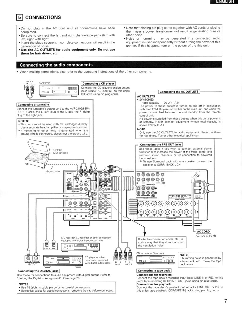
8 NGLISH onnecting video components To connect the video signal, connect using a 75 Ω/ohms video signal cable cord. Using an improper cable can result in a drop in video quality. When making connections, also refer to the operating instructions of the other components. The AVR-05/885 is equipped with a function for up-converting video signals. The signal connected to the video signal terminal is output to the S-Video and component video monitor out terminals. The R OUT terminals have no conversion function, so when recording only connect the video terminals. AUDIO OUT R L R L VIDO OUT TV or DS tuner onnecting a TV/DS tuner TV or DS onnect the TV s or DS tuner s video output jack (VIDO OUTPUT) to the VIDO (yellow) TV or DS IN jack using a 75 Ω/ohms video coaxial pin plug cord. onnect the TV s or DS tuner s audio output jacks (AUDIO OUTPUT) to the AUDIO TV or DS IN jacks using pin plug cords. AUDIO OUT R L VIDO OUT DVD player or video disc player (VDP), etc. R L onnecting a DVD player or a video disc player (VDP) DVD onnect the video disc player s video output jack (VIDO OUTPUT) to the VIDO (yellow) DVD IN jack using a 75 Ω/ohms video coaxial pin plug cord. onnect the video disc player s analog audio output jacks (ANALOG AUDIO OUTPUT) to the AUDIO DVD IN jacks using pin plug cords. VDP can be connected to the VDP jacks in the same way. Monitor TV VIDO IN L R L R R R L onnecting a Monitor TV MONITOR OUT onnect the TV s video input jack (VIDO INPUT) to the VIDO MONITOR OUT jack using a 75 Ω/ohms video coaxial pin plug cord. L R L R L Note on connecting the digital input jacks Only audio signals are inputs to the digital input jacks. For details. (See page 7) R L R L Video deck R L R L OUT IN OUT IN AUDIO VIDO R L R L Video deck R L R L OUT IN OUT IN AUDIO VIDO onnecting a video decks There are two sets of video deck (VR) jacks, so two video decks can be connected for simultaneous recording or video copying. Video input/output connections: onnect the video deck s video output jack (VIDO OUT) to the VIDO (yellow) VR- IN jack, and the video deck s video input jack (VIDO IN) to the VIDO (yellow) VR- OUT jack using 75 Ω/ohms video coaxial pin plug cords. onnecting the audio output jacks onnect the video deck s audio output jacks (AUDIO OUT) to the AUDIO VR- IN jacks, and the video deck s audio input jacks (AUDIO IN) to the AUDIO VR- OUT jacks using pin plug cords. onnect the second video deck to the VR- jacks in the same way. 8
9 NGLISH onnecting the video components equipped with S-Video jacks When making connections, also refer to the operating instructions of the other components. A note on the S input jacks The input selectors for the S inputs and Video inputs work in conjunction with each other. The AVR-05/885 is equipped with a function for converting video signals. The signal connected to the S-Video signal terminal is output to the composite video and component video monitor out terminals. The R OUT terminals have no conversion function, so when recording only connect the S-Video terminals. VIDO OUT S-VIDO OUT DVD player or video disc player (VDP) onnecting a DVD player or a video disc player (VDP) DVD/VDP onnect the DVD player s S-Video output jack to the S- VIDO DVD IN jack using a S-Video connection cord. VDP can be connected to the VDP jacks in the same way. It is also possible to connect a video disc player, DVD player, video camcorder, game machine, etc., to the V. AUX jacks. S-VIDO IN VIDO IN VIDO OUT VIDO OUT S-VIDO OUT Monitor TV S-VIDO OUT IN onnecting a monitor TV MONITOR OUT onnect the TV s S video input (S-VIDO INPUT) to the S-VIDO MONITOR OUT jack using a S jack connection cord. TV or satellite broadcast tuner onnecting a TV or DS tuner onnect the TV s or DS tuner s S video output jack (S-VIDO OUTPUT) to the S-VIDO TV or DS IN jack using an S-Video connection cord. Video deck VIDO IN onnecting the video decks onnect the video deck s S output jack (S-OUT) to the S-VIDO VR- IN jack and the video deck s S input jack (S-IN) to the S-VIDO VR- OUT jack using S-Video connection cords. onnect the video deck s S output jack (S-OUT) to the S-VIDO VR- IN jack and the video deck s S input jack (S-IN) to the S-VIDO VR- OUT jack using S-Video connection cords. VIDO OUT S-VIDO OUT IN Video deck VIDO IN onnect the components audio inputs and outputs as described on page 8. 9
10
11 NGLISH onnecting the antenna terminals DIRTION OF ROADASTING STATION FM INDOOR ANTNNA (An Accessory) FM ANTNNA 75 Ω/ohms OAXIAL AL AM OUTDOOR ANTNNA GROUND AM LOOP ANTNNA (An Accessory) An F-type FM antenna cable plug can be connected directly. AM loop antenna assembly onnection of AM antennas onnect to the AM antenna terminals.. Push the lever.. Insert the conductor.. Return the lever. 4 Remove the vinyl tie and take out the connection line. a. With the antenna on top any stable surface. b. With the antenna attached to a wall. Mount Installation hole Mount on wall, etc. end in the reverse direction. Note to ATV system installer: This reminder is provided to call the ATV system installer s attention to Article of the N which provides guidelines for proper grounding and, in particular, specifies that the cable ground shall be connected to the grounding system of the building, as close to the point of cable entry as practical. NOTS: Do not connect two FM antennas simultaneously. ven if an external AM antenna is used, do not disconnect the AM loop antenna. Make sure AM loop antenna lead terminals do not touch metal parts of the panel.
12 NGLISH onnecting the external input (XT. IN) jacks These jacks are for inputting multi-channel audio signals from an outboard decoder, or a component with a different type of multi-channel decoder, such as a DVD Audio player, a multi-channel SAD player, or other future multi-channel sound format decoder. When making connections, also refer to the operating instructions of the other components. R L R L Front Surround Subwoofer enter Decoder with 6-channel analog output For instructions on playback using the external input (XT. IN) jacks, see page 4. onnecting the video component equipped with V.AUX jacks To connect the video signal, connect using a 75 Ω/ohms video signal cable cord. VOLUM LVL MASTR VOLUM Video game OUTPUT R L OPTIAL VIDO OUT S-VIDO OUT onnecting a Video game component onnect the Video game component s output jacks to this unit s V. AUX INPUT jacks. DTS OUTPUT SURROUND AK ZON R L ST ª TUNING VIDO SLT DIMMR STATUS DIRT / STRO V.AUX INPUT L S-VIDO VIDO L AUDIO R OPTIAL STUP MI R SURROUND MOD SURROUND PARAMTR SLT TON ONTROL TON DFAT LIN OUT DIGITAL OUT VIDO OUT S-VIDO OUT AV SURROUND RIVR AVR-05 R L Video camera OUTPUT VIDO OUT S-VIDO OUT onnecting a video camera component onnect the video camera component s output jacks to this unit s V. AUX INPUT jacks. R L LIN OUT VIDO OUT S-VIDO OUT
13
14 NGLISH Speaker system connections onnect the speaker terminals with the speakers making sure that like polarities are matched ( with, with ). Mismatching of polarities will result in weak central sound, unclear orientation of the various instruments, and the sense of direction of the stereo being impaired. When making connections, take care that none of the individual conductors of the speaker cord come in contact with adjacent terminals, with other speaker cord conductors, or with the rear panel. NOT: NVR touch the speaker terminals when the power is on. Doing so could result in electric shocks. Speaker Impedance When speaker systems A and are use separately, speakers with an impedance of 6 to 6 Ω/ohms can be connected for use as front speakers. e careful when using two pairs of front speakers (A + ) at the same time, since use of speakers with an impedance of to 6 Ω/ohms. Speakers with an impedance of 6 to 6 Ω/ohms can be connected for use as center and surround and surround back speakers. The protector circuit may be activated if the set is played for long periods of time at high volumes when speakers with an impedance lower than the specified impedance are connected. onnecting the speaker cords. Loosen by turning counterclockwise.. Insert the cord.. Tighten by turning clockwise. onnecting banana plugs anana plug Turn clockwise to tighten, then insert the banana plug. Protector circuit This unit is equipped with a high-speed protection circuit. The purpose of this circuit is to protect the speakers under circumstances such as when the output of the power amplifier is inadvertently short-circuited and a large current flows, when the temperature surrounding the unit becomes unusually high, or when the unit is used at high output over a long period which results in an extreme temperature rise. When the protection circuit is activated, the speaker output is cut off and the power supply indicator LD flashes. Should this occur, please follow these steps: be sure to switch off the power of this unit, check whether there are any faults with the wiring of the speaker cables or input cables, and wait for the unit to cool down if it is very hot. Improve the ventilation condition around the unit and switch the power back on. If the protection circuit is activated again even though there are no problems with the wiring or the ventilation around the unit, switch off the power and contact a DNON service center. Note on speaker impedance The protector circuit may be activated if the set is played for long periods of time at high volumes when speakers with an impedance lower than the specified impedance (for example speakers with an impedance of lower than 4 Ω/ohms) are connected. If the protector circuit is activated, the speaker output is cut off. Turn off the set s power, wait for the set to cool down, improve the ventilation around the set, then turn the power back on. 4
15
16 NGLISH 6 PART NAMS AND FUNTIONS Front Panel For details on the functions of these parts, refer to the pages given in parentheses ( ). #5 #4 # @!9 MASTR VOLUM FUNTION VOLUM LVL SIGNAL DIGITAL AUTO INPUT PM DTS OUTPUT SURROUND AK ZON INPUT MOD ANALOG XT. IN AND SHIFT ª PRST ª TUNING VIDO SLT DIMMR STATUS MAIN SOUR ZON / R SLT ON / STANDY ON OFF PHONS A SPAKR SURROUND AK 5H / 7H DIRT / STANDARD STRO STRO V.AUX INPUT SURROUND MOD SLT TON ONTROL SURROUND PARAMTR TON DFAT S-VIDO VIDO L AUDIO R OPTIAL STUP MI AV SURROUND RIVR AVR-05 q w e t u o!!4 r y i!0!!!5!6!7!8 q Power ON/STANDY switch...(, 9, 6) w Power indicator...(, 9) e Power switch...(, 9) r Headphones jack (PHONS)...(4) t ANALOG button...(40, 4) y SPAKR A/ buttons...(9, 64) u SURROUND AK button...(54) i Preset station select buttons...(6) o STANDARD button...(48, 50, 5, 54)!0 5H/7H STRO button...(58)! DIRT/STRO button...(4)! V. AUX INPUT terminals...(5, )! STUP MI jack...()!4 SURROUND MOD button...(4)!5 SURROUND PARAMTR button...(50, 58)!6 SLT knob...(4, 5, 59)!7 TON DFAT button...(4)!8 TON ONTROL button...(4)!9 MASTR VOLUM TUNING (up) / ª (down) STATUS DIMMR VIDO SLT OUTPUT indicator...(47, MASTR VOLUM INPUT mode SIGNAL AND button...(6) #0 XT. IN button...(40, 4) # Remote control sensor...(8) # INPUT MOD button...(40, 4) # ZON/R SLT button...(44, 47) #4 FUNTION knob...(40, 44, 47) #5 MAIN button...(40) 6
17 NGLISH Remote control unit For details on the functions of these parts, refer to the pages given in parentheses ( ). LD (indicator)...(5, 8) Remote control signal transmitter...(8) POWR buttons...(, 5~7, 9) ZON buttons...(47) MAIN buttons...(47) SURROUND buttons...(4, 48, 58) Input source selector buttons...(5~8, 40) Tuner system/ System buttons...(4, 6, 7, 6) Mode selector switches...(4~6, 8) System buttons...(4, 6, 7) Master volume control buttons...(4) MUTING button...(4) SYSTM ST UP/ STUP button...(9, 6, 7) SURROUND PARAMTR/SYSTM button...(6, 7, 50) ursor buttons...(9, 6, 7, 5) H SLT (channel select)/ NTR button...(9, 6, 7, 49, 5) ON SRN/DISPLAY button...(6, 7, 56) SURROUND AK/RTURN button...(6, 7, 54) Test tone button...(48) SPAKR button...(9) VIDO SLT button...(4) DIMMR button...(44) INPUT MOD selector buttons...(40, 4) 7
18 NGLISH 7 USING TH RMOT ONTROL UNIT Following the procedure outlined below, insert the batteries before using the remote control unit. Range of operation of the remote control unit Point the remote control unit at the remote control sensor as shown on the diagram at the left. Approx. feet/7 m 0 0 NOTS: The remote control unit can be used from a straight distance of approximately feet/7 meters, but this distance will shorten or operation will become difficult if there are obstacles between the remote control unit and the remote control sensor, if the remote control sensor is exposed to direct sunlight or other strong light, or if operated from an angle. Neon signs or other devices emitting pulse-type noise nearby may result in malfunction, so keep the set as far away from such devices as possible. Inserting the batteries q Press as shown by the arrow and slide off. w Insert the R6P/AA batteries properly, as shown on the diagram. e lose the lid. NOTS: Use only R6P/AA batteries for replacement. e sure the polarities are correct. (See the illustration inside the battery compartment.) Remove the batteries if the remote control transmitter will not be used for an extended period of time. If batteries leak, dispose of them immediately. Avoid touching the leaked material or letting it come in contact with clothing, etc. lean the battery compartment thoroughly before installing new batteries. Have replacement batteries on hand so that the old batteries can be replaced as quickly as possible when the time comes. ven if less than a year has passed, replace the batteries with new ones if the set does not operate even when the remote control unit is operated nearby the set. (The included battery is only for verifying operation. Replace it with a new battery as soon as possible.) 8
19 NGLISH 8 STTING UP TH SYSTM Once all connections with other AV components have been completed as described in ONNTIONS (see pages 7 to 5), make the various settings described below on the monitor screen using the AVR-05/885 s on-screen display function. These settings are required to set up the listening room s AV system centered around the AVR-05/885. Use the following buttons to set up the system Set the slide switch to AUDIO. Use the following buttons to set up the system: SYSTM STUP button Press this to display the system setup on the display. URSOR buttons (, ª, 0, ) Press this change what appears on the display. NTR button Press this to switch the display. Also use this button to complete the setting. System setup items and default values (set upon shipment from the factory) System setup Default settings Auto Setup Power Amp Assignment Set this to switch the surround back channel s power amplifier for use for zone. SURROUND AK Speaker onfiguration Input the combination of speakers in your system and their corresponding sizes (SMALL for regular speakers, LARG for fullsize, full-range) to automatically set the composition of the signals output from the speakers and the frequency response. Front Sp. Large enter Sp. Small Surround Sp. Small Surround ack Sp. Small / spkrs Subwoofer Yes Delay Time This parameter is for optimizing the timing with which the audio signals are produced from the speakers and subwoofer according to the listening position. Front L Front R enter Surround L Surround R Surround ack L ft ft ft 0 ft 0 ft 0 ft Surround ack R 0 ft Subwoofer ft Subwoofer Mode This selects the subwoofer speaker for playing deep bass signals. Subwoofer mode = LF (Normal) rossover Frequency Set the frequency (Hz) below which the bass sound of the various speakers is to be output from the subwoofer. 80 Hz Test Tone This adjusts the volume of the signals output from the speakers and subwoofer for the different channels in order to obtain optimum effects. Front L Front R enter Surround L Surround R Surround ack L 0 d 0 d 0 d 0 d 0 d 0 d Surround ack R 0 d Subwoofer 0 d Digital In Assignment This assigns the digital input jacks for the different input sources. Input source Digital Inputs D DVD/VDP TV/DS VR- VR- DR/TAP OAXIAL OPTIAL OPTIAL OFF OFF OPTIAL omponent In Assignment This assigns the component video input jacks for the different video input sources. Input source omponent Inputs DVD/VDP TV/DS VR- VR- V. AUX VIDO VIDO VIDO OFF OFF Video Input Mode Set the input signal to be output from the monitor output terminal. AUTO Auto Surround Mode Auto surround mode function setting. Auto Surround Mode = ON xt. In SW Level Set the xt. In Subwoofer channel playback level. xt. In SW Level = +5 d Power AMP Assignment On Screen Display Set this to switch the surround back channel s power amplifier for use for Zone. This sets whether or not to display the on-screen display that appears on the monitor screen when the controls on the remote control unit or main unit are operated. A setting to prevent flickering. Surround ack On Screen Display = ON /Mode 9
20 NGLISH System setup Default settings A ~ A8 ~ 8 ~ 8 D ~ D8 ~ 8 F ~ F8 G ~ G / 89. / 98. / 07.9 / 90. / 90. / 90. / 90. MHz 50 / 600 / 000 / 400 / 500 / 70 khz, 90. / 90. MHz 90. MHz 90. MHz 90. MHz Auto Tuner Presets FM stations are received automatically and stored in the memory. 90. MHz 90. MHz NOTS: The on-screen display signals are output with priority to the S-VIDO MONITOR OUT jack during playback of a video component. For example, if the TV monitor is connected to both the AVR-05/885 s S-Video and video monitor output jacks and signals are input to the AVR- 05/885 from a video source (VDP, etc.) connected to both the S-Video and video input jacks, the on-screen display signals are output with priority to the S-Video monitor output. If you wish to output the signals to the video monitor output jack, do not connect a cord to the S- VIDO MONITOR OUT jack. (For details, see page.) The AVR-05/885 s on-screen display function is designed for use with high resolution monitor TVs, so it may be difficult to read small characters on TVs with small screens or low resolutions. The setup menu is not displayed when headphone are being used. Speaker system layout asic system layout The following is an example of the basic layout for a system consisting of 8 speaker systems and a television monitor: Subwoofer enter speaker system Surround back speaker system Front speaker systems Set these at the sides of the TV or screen with their front surfaces as flush with the front of the screen as possible. Surround speaker systems 0
21 NGLISH efore setting up the system Refer to ONNTIONS (pages 7 to 5) and check that all connections are correct. ON / STANDY ON OFF Press the Power switch (button). ON The power turns on and indicator is light. Set the power switch to this position to turn the power on and off from the included remote control unit. OFF The power turns off and indicator is off. In this position, the power cannot be turned on and off from the remote control unit. Turn on the power. Press the Power ON/STANDY switch (button). 4 Press the SYSTM STUP button to enter the setting. *SYSTM ST UP NOT: Please make sure the AUDIO position of the slide switch on the remote control unit. 5 Press the NTR or (down) button to switch to the Auto Setup. NOT: Press the SYSTM STUP button again to finish system set up. System set up can be finished at any time. The changes to the settings made up to that point are entered. Auto setup The Auto Setup function of this unit performs an analysis of the speaker system to permit an appropriate automatic setting. When performing Auto Setup, an optional microphone is required for the setup. Measurement and setting details q : This sets the speaker connection mode, polarity, and bass reproduction ability. w : This sets the optimum delay time from each speaker corresponding to the listening position. e : This sets the volume that is output from each speaker. NOT: A loud test tone is output during the measurement. Please consider this should you be planning night time measurements, and consider not allowing small children into the listening room at this time.
22 PHONS A SPAKR SURROUND AK 5H / 7H STANDARD STRO DIRT / STRO V.AUX INPUT S-VIDO VIDO L AUDIO R OPTIAL STUP MI SURROUND MOD SURROUND PARAMTR SLT AV SURROUND RIVR TON ONTROL TON DFAT NGLISH onnecting the microphone for Auto Setup onnect the microphone for Auto Setup to the Setup Mic connector on the front panel of the unit. AVR-05 Listening position Place the microphone for Auto Setup at the actual listening position which will be at the same height as your ears. Use a tripod or level surface at positioning. Setting the Auto Setup Use the (left) button to switch the Auto Setup mode. Press the NTR or (down) button to switch to the speaker configuration set up. AutoSet <YS heck the Power Amp Assign setting. When Surround ack is selected, the test tone during Auto Setup will be output from the Surround ack speaker. When ZON is selected, change the setting to ZON The test tone during Auto Setup is set so that it will not be output to ZON (Another room). q Select the Power Amp Assign setting. w Select Surround ack or ZON. AutoSet S > NOT: When ZON is selected at System Setup Menu Power Amp Assign, surround back speaker is not displayed. q Select the Start. w Press the (left) button to start Auto Setup. AutoSet <Start
23 NGLISH 4 Start the measurements. Measurement of each channel is performed as follows. Display FL FR SW SL SR SL SR NOTS: Measurement is canceled when MASTR VOLUM is operated while the Auto Setup is performed. Set the volume to halfway and set the crossover frequency to the maximum or Low pass filter off if your subwoofer speaker can adjust the output volume and the crossover frequency. Only the front speakers (A) is measured. ven if the front speakers () is set, the setting automatically switches to the front speakers (A) once measurements are completed. Subwoofer speaker is measured twice. When ZON is selected, this is not displayed. After each channel is measured, alculating appears. The display switches to Auto Setup check screen automatically. About automatic retry Remeasurement starts automatically to receive proper result of measurement. Remeasurement is performed to times, and Retry or Retry is displayed on screen during remeasurement. About the error message These error screens will be displayed when performing the measurements of Auto Setup and the automatic measurements can not be completed because of the speaker arrangement, measurement environment, or other factors. Please check the following matters, reset the pertinent items, and measure again. When there is too much noise in the room, the speakers may not be detected properly. Should this happen, perform the measurements when the noise level is low, or switch off the power of the equipment that is producing the noise for the duration of the measurements. q This screen will be displayed when the speakers required for producing suitable reproduction have not been detected. The front L and front R speakers were not properly detected. Only one channel of the surround speakers was detected. Sound was output from the R channel when only one surround back speaker was connected. The surround back was detected, but the surround speaker was not detected. heck that the pertinent speakers are properly connected (see page 5). w This screen will be displayed when the speaker polarity is connected in reverse. heck the polarity of the pertinent speakers. For some speakers, the screen below may be displayed even though the speakers are properly connected. If so, select Skip0. e This screen will be displayed when accurate measurements cannot be made due to the input level to the microphone being too high. Set up the speakers so that their position is farther away from the listening position. Lower the volume of the subwoofer speaker. r This screen will be displayed when the measurement microphone is not connected, or when all of the speakers have not been detected. onnect the measurement microphone to the microphone connector. heck the speaker connections.
24 NGLISH heck of the measurement results Select the items. The measurement results of each item can be checked here. A.Set Sponf.k Press the NTR button and display the verification screen. [Speaker onfig. heck] [Delay Time heck] [hannel Level heck] NOT: When measurements have been made using the measurement microphone, speakers with a built-in filter such as subwoofers might be set with a value that differs from the physical distance because of the internal electrical delay. If the check ends, press the NTR button again. 4 Select from the following three items based on the measurement results. Store : Set with the checked measurement value. Retry : Perform the measurement again. ancel : ancel the checked measurement value. 5 A.Set <Store When the Store is selected, all parameters are stored up and switch to the SUWOOFR MOD setting. 4
25 NGLISH Setting the type of speakers Set up in function of your speaker systems. Performing this setup optimizes the system. The composition of the signals output to the different channels and the frequency response are adjusted automatically according to the combination of speakers actually being used. Set whether or not speakers are connected and, if so, their size parameters. To select the speaker Front Sp. enter Sp. Front Sp. Subwoofer Listening position Surround Sp. Surround Sp. Surround back Sp. To select the parameter FRONT LARG Press the NTR or (down) button to enter the settings and switch to the SPAKR DISTAN setting. Parameters Large...Select this when using speakers that have sufficient performance for reproducing bass sound below the frequency set for the rossover Frequency mode. Small...Select this when using speakers that do not have sufficient performance for reproducing bass sound below the frequency set for the rossover Frequency mode. When this is set, bass sound with a frequency below the frequency set for the rossover Frequency mode is sent to the subwoofer. None...Select this when no speakers are installed. Yes/No...Select Yes when a subwoofer is installed, No when a subwoofer is not installed. spkrs/spkr...set the number of speakers to be used for the surround back channel. If the subwoofer has sufficient low frequency playback capacity, good sound can be achieved even when Small is set for the front, center and surround speakers. 5
26 NGLISH Setting the delay time Input the distance between the listening position and the different speakers to set the delay time for the surround mode. Preparations: Measure the distances between the listening position and the speakers (L to L5) on the diagram at the right). L: Distance between center speaker and listening position L: Distance between front speakers and listening position L: Distance between surround speakers and listening position L4: Distance between surround back speaker and listening position L5: Distance between subwoofer and listening position AUTION: Please note that the difference for every speaker should be 5 ft or less. NOTS: No setting when None has been selected for the Speaker onfiguration setting. Surround back is not displayed when ZON is set with the POWR AMP ASSIGN setting. FL enter Subwoofer L L SL L5 L L4 SL FR Listening position SR SR Select the speaker to be set. 8 FRONT L ft Set the distance between the speaker and listening position. The distance changes in units of foot (0. meters) each time the button is pressed. Select the value closest to the measured distance. Press the NTR or (down) button to enter the setting and switch the SUWOOFR MOD setting. 6
27 NGLISH Setting the Subwoofer mode and rossover Frequency This screen is not displayed when not using a subwoofer. Set the crossover frequency and subwoofer mode according to the speaker system being used. Select the Subwoofer Mode. Select the setting. 6SW MOD NORM Select the rossover Frequency mode. Select the frequency. 7R.OVR 80Hz 40 / 60 / 80 / 00 / 0 / 50 / 00 / 50 Hz can be selected. Press the NTR or (down) button to enter the setting and switch to the Test Tone setting. NOTS: Assignment of low frequency signal range The signals produced from the subwoofer channel are LF signals (during playback of Dolby Digital or DTS signals) and the low frequency signal range of channels set to SMALL in the setup. The low frequency signal range of channels set to LARG are produced from those channels. rossover Frequency When Subwoofer is set to Yes at the Speaker onfiguration Setting, set the frequency (Hz) below which the bass sound of the various speakers is to be output from the subwoofer (the crossover frequency). For speakers set to Small, sound with a frequency below the crossover frequency is cut, and the cut bass sound is output from the subwoofer instead. NOT:For ordinary speaker systems, we recommend setting the crossover frequency to 80 Hz. When using small speakers, however, setting the crossover frequency to a high frequency may improve frequency response for frequencies near the crossover frequency. Subwoofer mode The subwoofer mode setting is only valid when Large is set for the front speakers and YS is set for the subwoofer in the Speaker onfiguration settings (see page 5). When the LF+MAIN playback mode is selected, the low frequency signal range of channels set to Large are produced simultaneously from those channels and the subwoofer channel. In this playback mode, the low frequency range expand more uniformly through the room, but depending on the size and shape of the room, interference may result in a decrease of the actual volume of the low frequency range. Selection of the LF play mode will play the low frequency signal range of the channel selected with Large from that channel only. Therefore, the low frequency signal range that are played from the subwoofer channel are only the low frequency signal range of LF (only during Dolby Digital or DTS signal playback) and the channel specified as Small in the setup menu. Select the play mode that provides bass reproduction with quantity. When the subwoofer is set to Yes, bass sound is output from the subwoofer regardless of the subwoofer mode setting in surround modes other than Dolby/DTS. In surround modes other than Dolby Digital and DTS, if the subwoofer is set to YS, the low frequency portion is always output to the subwoofer channel. For details, refer to Surround Modes and Parameters on page 60. 7
AV SURROUND RECEIVER AVR-4806 OPERATING INSTRUCTIONS
 AV SURROUND RIVR AVR-4806 OPRATING INSTRUTIONS SAFTY PRAUTIONS AUTION RISK OF LTRI SHOK DO NOT OPN AUTION: TO RDU TH RISK OF LTRI SHOK, DO NOT RMOV OVR (OR AK). NO USR-SRVIAL PARTS INSID. RFR SRVIING TO
Monochrome Video Monitors
 Instructions for Use Monochrome Video Monitors En F D E NL I LTC 2009 LTC 2012 LTC 2017 Philips Communication & Security Systems GB F D E NL I Instructions for Use...1.1 Mode d emploi...2.1 Bedienungsanleitung...3.1
AV SURROUND RECEIVER AVR-4806CI OPERATING INSTRUCTIONS
 AV SURROUND RIVR AVR-4806I OPRATING INSTRUTIONS SAFTY PRAUTIONS AUTION RISK OF LTRI SHOK DO NOT OPN AUTION: TO RDU TH RISK OF LTRI SHOK, DO NOT RMOV OVR (OR BAK). NO USR-SRVIABL PARTS INSID. RFR SRVIING
DM-1CH SD DVB-T MODULATOR INSTRUCTION MANUAL
 DM-1CH SD DVB-T MODULATOR INSTRUCTION MANUAL 2. Caution Statements and Table of Contents Table of Contents 2. Caution Statements and Table of contents 3. Important Safety Instructions 4. Important Safety
Wired to Wireless Camera Converter
 Wired to Wireless Camera Converter Instruction Manual English Version 1.0 MODEL: WL401BNC www.lorexcctv.com Copyright (c) 2006 LOREX Technology Inc. Thank you for purchasing the 2.4 GHz Wireless Camera
2.4 GHz WIRELESS VIDEO SENDER SYSTEM MODEL: VS6234
 2.4 GHz WIRELESS VIDEO SENDER SYSTEM MODEL: VS6234 Please read this manual thoroughly before operating this system OPERATING INSTRUCTIONS 03/02 1 SAFETY INSTRUCTIONS CAUTION! RISK OF ELECTRIC SHOCK. DO
CR42 LANCASTER
 10-4-08 CR42 LANCASTER 910-262800-0020-100 WARRANTY Crosley Radio Products are warranted against defects in material and workmanship for a period of 90 days beginning from the date of sale to the original
2.0 Wall Mount TV Soundbar Instruction Manual
 8010275 2.0 Wall Mount TV Soundbar Instruction Manual Read all of the instructions before using this soundbar and keep the manual in a safe place for future reference. Safety Information CA UT IO N RISK
Wireless 4 Channel Receiver with 2 Night Vision cameras
 Wireless 4 Channel Receiver with 2 Night Vision cameras Instruction Manual English Version 2.0 MODEL: SHS-4WLS www.lorexcctv.com Copyright 2006 LOREX Technology Inc. Thank you for purchasing the SHS-4WLS.
SW 50. Powered Subwoofer with Built-in Stereo Crossover
 Owner s Manual SW 50 ed Subwoofer with Built-in Stereo Crossover Congratulations on your new purchase and welcome to the AudioSource family of satisfied customers. We trust you will continue to enjoy the
Evolution Digital HD Set-Top Box Important Safety Instructions
 Evolution Digital HD Set-Top Box Important Safety Instructions 1. Read these instructions. 2. Keep these instructions. 3. Heed all warnings. 4. Follow all instructions. 5. Do not use this apparatus near
HD Digital Set-Top Box Quick Start Guide
 HD Digital Set-Top Box Quick Start Guide Eagle Communications HD Digital Set-Top Box Important Safety Instructions WARNING TO REDUCE THE RISK OF FIRE OR ELECTRIC SHOCK, DO NOT EXPOSE THIS PRODUCT TO RAIN
AV SURROUND RECEIVER AVR-5805CI OPERATING INSTRUCTIONS
 AV SURROUND RIVR AVR-5805I OPRATING INSTRUTIONS SAFTY PRAUTIONS AUTION RISK OF TRI SHOK DO NOT OPN AUTION: TO RDU TH RISK OF TRI SHOK, DO NOT RMOV OVR (OR AK). NO USR-SRVIA PARTS INSID. RFR SRVIING TO
9" B/W MONITOR CEM-09/09A-2 12" B/W MONITOR CEM-12/12A-2 OPERATION MANUAL
 9" B/W MONITOR CEM-09/09A-2 12" B/W MONITOR CEM-12/12A-2 OPERATION MANUAL CONTENTS PRECAUTIONS FOR USE AND INSTALLATION IMPORTANT SAFEGAURDS SAFETY INSTRUCTIONS INSTRUCTION MANUAL CLASS B COMPUTING DEVICES
CAUTION RISK OF ELECTRIC SHOCK NO NOT OPEN
 Evolution Digital HD Set-Top Box Important Safety Instructions 1. Read these instructions. 2. Keep these instructions. 3. Heed all warnings. 4. Follow all instructions. 5. Do not use this apparatus near
D108S INSTRUCTION MANUAL
 D108S INSTRUCTION MANUAL Contents Warnings & Precautions... 2 Important Safety Instructions... 3 In the Box & Features... 4 Powering the Unit... 5 Playing and Programming a DVD or CD... 6 Viewing a Photo
~ Instruction Manual ~
 ~ DJ-5 Professional Preamp mixer ~ 0 0 0 0 10 10 10 10 EVE MASTE GAIN GAIN 0 10 CUE EVE CH 1 CH 2 CUE PAN INE INE POWE FADE STAT FADE STAT HEADPHONES ~ Instruction Manual ~ ~ Important Safety Instructions
Color Video Monitor. Instruction Manual. Read this manual thoroughly before use, and retain it for maintenance.
 Color Video Monitor Instruction Manual Read this manual thoroughly before use, and retain it for maintenance. The product s exterior design and specifications may subject to change without prior notice
ZVOX AccuVoice TV Speaker Model AV203
 ZVOX AccuVoice TV Speaker Model AV203 SETUP & OPERATION www.zvoxaudio.com 2 ZVOX AccuVoice TV Speaker Setup & Operation READ THIS FIRST Important Safety Instructions For ZVOX Audio System WARNING TO PREVENT
ZVOX AccuVoice TV Speaker Model AV203
 ZVOX AccuVoice TV Speaker Model AV203 SETUP & OPERATION www.zvoxaudio.com READ THIS FIRST Important Safety Instructions For ZVOX Audio System WARNING TO PREVENT FIRE OR SHOCK HAZARD, DO NOT EXPOSE THIS
HD Digital MPEG2 Encoder / QAM Modulator
 HD Digital MPEG2 Encoder / QAM Modulator HDMI In QAM Out series Get Going Guide ZvPro 800 Series is a one or two-channel unencrypted HDMI-to-QAM MPEG 2 Encoder / QAM Modulator, all in a compact package
HD Digital MPEG2 Encoder / QAM Modulator
 HD Digital MPEG2 Encoder / QAM Modulator YPrPb VGA In QAM Out series Get Going Guide ZvPro 600 Series is a one or two-channel Component or VGA-to-QAM MPEG 2 Encoder/ Modulator, all in a compact package
SDM1000. Satellite Demodulator Module INSTRUCTION MANUAL SDM Satellite Demodulator Module
 SDM1000 Satellite Demodulator Module INSTRUCTION MANUAL Model Item # Description SDM1000 1002576 Satellite Demodulator Module 937-746-4556 www.rldrake.com 2015 R.L. Drake Holdings, LLC. Rev: 041715 / 651230500A
User Guide. Connecting the Explorer 1850 Digital Home Communications Terminal
 User Guide Connecting the Explorer 1850 Digital Home Communications Terminal Notice for CATV Installers Notice for CATV Installers: If you are a CATV installer, read the information in the box below. 2
2.4 GHz WIRELESS VIDEO SECURITY SYSTEM
 2.4 GHz WIRELESS VIDEO SECURITY SYSTEM Please read this manual thoroughly before operating this system OPERATING INSTRUCTIONS Rev 03/01-1 SPECIFICATIONS WIRELESS CAMERA Image sensor Lens Picture element
CONTENTS. Seville Lectern Sound System Owners Manual. A Message from the President
 CONTENTS A Message from the President Congratulations on purchasing an Anchor Audio sound system, the choice of thousands of satisfied customers including the White House, prestigious universities, school
INTRODUCTION. WARNING To prevent fire or shock hazard, do not expose this unit to moisture.
 Multi-function Remote Control Built-in Hands Free Speaker Phone Cable Ready 125 Channel TV Tuner Internal Stereo Speakers Under Cabinet / Table Top Mounting A/V Input AM/FM Radio Tuner - 1 - INTRODUCTION
Operating Instructions
 Operating Instructions SDI Input board Model No. AV-HS04M1 РУССКИЙ FRANÇAIS DEUTSCH ENGLISH ESPAÑOL ITALIANO Before operating this product, please read the instructions carefully and save this manual for
HD Digital MPEG2 Encoder / QAM Modulator Get Going Guide
 series HD Digital MPEG2 Encoder / QAM Modulator Get Going Guide HDb2640 HDb2620 HDb2540 HDb2520 The HDbridge 2000 Series is a combination HD MPEG 2 Encoder and frequency-agile QAM Modulator, all in a 1RU
User Guide. Connecting the Explorer 3350 Digital Home Communications Terminal
 User Guide Connecting the Explorer 3350 Digital Home Communications Terminal Notice for CATV Installers CATV Installers Notice If you are a CATV installer, read the information in the box below. CONTENTS
AV SURROUND RECEIVER AVR-488
 AV SURROUND RECEIVER AVR-488 Owner s Manual Manuel de l Utilisateur FRANCAIS n SAFETY PRECAUTIONS CAUTION RISK OF ELECTRIC SHOCK DO NOT OPEN CAUTION: TO REDUCE THE RISK OF ELECTRIC SHOCK, DO NOT REMOVE
Introduction. Important Safety Instructions
 Introduction Congratulations on purchasing your Eviant Portable Digital TV. On June 12, 2009 the conversion to digital television broadcasting will be complete all throughout the United States and Puerto
AV SURROUND RECEIVER AVR-588
 AV SURROUND RECEIVER AVR-588 Owner s Manual Manuel de l Utilisateur FRANCAIS n SAFETY PRECAUTIONS CAUTION RISK OF ELECTRIC SHOCK DO NOT OPEN CAUTION: TO REDUCE THE RISK OF ELECTRIC SHOCK, DO NOT REMOVE
CR10 REMOTE CONTROL SYSTEM
 CR10 REMOTE CONTROL SYSTEM CR10 REMOTE CONTROL SYSTEM IMPORTANT SAFETY INSTRUCTIONS THESE INSTRUCTIONS ARE TO PROTECT YOU AND THE MclNTOSH INSTRUMENT. BE SURE TO FAMILIARIZE YOURSELF WITH THEM 1. Read
Register your product and get support at SDV5122/27. EN User manual
 Register your product and get support at www.philips.com/welcome SDV5122/27 User manual Contents 1 Important 4 Safety 4 Notice for USA 5 Notice for Canada 5 Recycling 6 English 2 Your SDV5122 7 Overview
ESC333. simple setup guide
 TM ESC333 simple setup guide thank you for choosing JBL. For more than 50 years, JBL has been involved in every aspect of music and film recording and reproduction, from live performances to the recordings
DTV-140. Instruction Manual. ATSC High-Definition (HD) Set Top Box. Please read this manual carefully before operation
 Set Top Box. Please read this manual carefully before operation") DTV-140 ATSC High-Definition (HD) Set Top Box Instruction Manual Please read this manual carefully before operation PRECAUTIONS For Customer Use: Enter below the serial number that is located on the unit.
DTV-140 ATSC High-Definition (HD) Set Top Box Instruction Manual Please read this manual carefully before operation PRECAUTIONS For Customer Use: Enter below the serial number that is located on the unit.
CONGRATULATIONS CONTENTS
 OWNER'S MANUAL CONGRATULATIONS Thank you for your purchasing the VESTAX PMC-05ProIII, Professional Mixing Controller. We suggest that you read through this owner's manual thoroughly so that you may enjoy
After Ref.No:
 Ref.No:171.130 Safety Instructions 1. Read Instructions-All the safety and operating instructions should be read before this product is operated. 2. Retain Instruction- The safety and operating instruction
CFT2200. User Guide 0(18 6(/(&7 (17(5 92/80( &+$11(/ ( 6 6 $ * ( 6
 CFT2200 User Guide 0 ( 6 6 $ * ( 6 0(18 6(/(&7 (17(5 92/80( &+$11(/ &$87,21 5,6.Ã2)Ã(/(&75,&Ã6+2&. &$87,21 75('8&(Ã7+(Ã5,6.Ã2)Ã(/(&75,&Ã6+2&. '127Ã5(029(Ã&29(5Ã25Ã%$&. 186(56(59,&($%/(Ã3$576Ã,16,'( 5()(5Ã6(59,&,1*Ã748$/,),('Ã6(59,&(Ã3(56211(/
Passport Player Owner s Manual
 Passport Player Owner s Manual Passport_manual_Rev1_1.indd 1 Contents Welcome.......................................................... 1 What s in the box?.......................................................
CAMERA KIT USE AND CARE GUIDE. Black & White Plastic Casing Camera Kit
 USE AND CARE GUIDE CAMERA KIT Black & White Plastic Casing Camera Kit Before operating the unit, please read this manual thoroughly and retain it for future reference. WARNING WARNING TO REDUCE THE RISK
LTC 113x & LTC123x FlexiDome Series Fixed Dome Cameras
 LTC 113x & LTC123x FlexiDome Series Fixed Dome Cameras Eng Installation Instructions F D E NL I IMPORTANT SAFEGUARDS 1. Read Instructions All the safety and operating instructions should be read before
Q-TV2. User Manual. for Screens
 Q-TV2 User Manual for 30-42 Screens Contents Introduction 02 Safety Guidelines 03 Getting started 03 Potential Uses 04 Carton Contents 05 Q-TV2 Controls 05 Remote Fixings 06 Fixing Rails 07 Fitting Q-TV2
AV SURROUND RECEIVER AVR-788
 AV SURROUND RECEIVER AVR-788 Owner s Manual Manuel de l Utilisateur FRANCAIS n SAFETY PRECAUTIONS CAUTION RISK OF ELECTRIC SHOCK DO NOT OPEN CAUTION: TO REDUCE THE RISK OF ELECTRIC SHOCK, DO NOT REMOVE
ZVOX AccuVoice TV Speaker MODEL AV150.
 ZVOX AccuVoice TV Speaker MODEL AV150 www.zvoxaudio.com READ THIS FIRST Important Safety Instructions For ZVOX Audio System WARNING TO PREVENT FIRE OR SHOCK HAZARD, DO NOT EXPOSE THIS APPLIANCE TO RAIN
4 PORT HDMI SWITCH
 4 PORT HDMI SWITCH 1518896 IMPORTANT SAFEGUARDS OF HDMI SWITCH PRODUCTS PLEASE READ CAREFULLY THE FOLLOWING SAFEGUARDS THAT ARE APPLICABLE TO YOUR EQUIPMENT 1. Read instructions - All the safety and operating
By CHANNEL VISION. Flush Mount Amplifier A0350
 Spkrs Local In IR In 24VDC A0350 10 The A0350 can be used with Channel Vision s CAT5 audio hubs to provide a powerful 50Watts per channel in the listening zone. Alternatively, the A0350 can be added to
17 19 PROFESSIONAL LCD COLOUR MONITOR ART
 17 19 PROFESSIONAL LCD COLOUR MONITOR ART. 41657-41659 Via Don Arrigoni, 5 24020 Rovetta S. Lorenzo (Bergamo) http://www.comelit.eu e-mail:export.department@comelit.it WARNING: TO REDUCE THE RISK OF FIRE
Connecting the Explorer 3300 Digital Home Communications Terminal
 User Guide Connecting the Explorer 3300 Digital Home Communications Terminal POWE VO CH+ VO+ SEECT GUIDE INFO EXIT CH SETTINGS Notice for CATV Installers CATV Installers Notice If you are a CATV installer,
User Manual AM Watt Professional Mixing Amplifier. Table of Contents. First Things First
 AM-170 250-Watt Professional Mixing Amplifier User Manual NOTE: To ensure this system works safely and to its fullest potential, please read the User Manual before use, and keep it handy for future reference.
 Register your product and get support at www.philips.com/welcome SWS3435S/27 SWS3435H/37 EN User manual Contents 1 Important 4 Safety 4 English 2 Your SWS3435 6 Overview 6 3 Installation 7 Connect the
D1816 INSTRUCTION MANUAL
 D1816 INSTRUCTION MANUAL Contents Warnings & Precautions... 2 Important Safety Instructions... 3 In the Box, Features, & Powering the Unit... 4 Composite Video Output: Connecting a Television... 5 S-Video
TS2.8 Sub OWNER S MANUAL
 TS2.8 Sub OWNER S MANUAL TS2.8 Sub CONTENTS IMPORTANT SAFETY INSTRUCTIONS 03 WARNINGS 03 FUSE PROTECTION 04 WARNING: STRONG MAGNETIC FIELD 04 EMC / EMI 04 ECODESIGN STANDBY POWER CONSUMPTION 04 WARRANTY
ZvBox 150. HD video distribution over COAX Get Going Guide
 ZvBox 150 HD video distribution over COAX Get Going Guide ZvBox 150 is an HD MPEG 2 Encoder and frequency agile QAM Modulator. It allows you to convert any HD video source, Component or RGB (VGA), in real
28 4K LED monitor. User Manual M284K
 28 4K LED monitor User Manual M284K CONTENTS Safety Information... 2 What s included..... 4 Getting Started....... 8 Troubleshooting.... 14 Specification.... 15 2 of 15 SAFETY INFORMATION Read these instructions
Modulator Installation Manual
 Warranty Multiplex Technology, Inc. warrants this product to be free from defects in materials and workmanship for a period of one year from the date of purchase or MTI will repair, or at its option, replace
User Manual LED TV CLOUD TV 55SU CLOUD TV 65SU. Design and Specification are subject to change without prior notice
 User Manual Thank you for purchasing CloudWalker LED TV. Please feel free to reach out to us for any service related query/complaints or for any feedback/suggesstions on the contact details mentioned below
OWNER S MANUAL EVOLUTION SERIES POWERED SUBWOOFER ES-SUB-EVO6-100
 OWNER S MANUAL EVOLUTION SERIES POWERED SUBWOOFER ES-SUB-EVO6-100 Important Safety Instructions CAUTION RISK OF ELECTRIC SHOCK! DO NOT OPEN! ATTENTION! RISQUE DE CHOC! ÉLECTRIQUE PAS OUVRIR! The lightning
Technical Specifications
 INSTALLATION SHEET AND OPERATORS MANUAL General Description: The is a mixer/preamplifier that includes 6 channels that each include a microphone input at screw terminals and an aux input at an RCA jack.
HDMI 5x1 Switch B-240-HDSWTCH-5X1 INSTALLATION MANUAL
 HDMI 5x1 Switch B-240-HDSWTCH-5X1 INSTALLATION MANUAL IMPORTANT SAFETY INSTRUCTIONS To reduce the risk of fire or electric shock, read and follow all instructions and warnings in this manual. Keep this
2.4 GHz WIRELESS SURVEILLANCE SYSTEM
 2.4 GHz WIRELESS SURVEILLANCE SYSTEM Operating Instructions Tested Comply With FCC Standards Model # TBM-18 BEFORE OPERATING THIS PRODUCT, READ, UNDERSTAND, AND FOLLOW THESE INSTRUCTIONS. Be sure to save
AUTO - SCANNING WITH DIGITAL CONTROL LCD COLOR MONITOR FS-L1903C. User manual (Rev.01) SMITHS HEIMANN
 SMITHS HEIMANN") AUTO - SCANNING WITH DIGITAL CONTROL LCD COLOR MONITOR FS-L1903C User manual (Rev.01) SMITHS HEIMANN www.smithsdetection.com Table of Contents Safety Instructions... 5 Accessories... 8 Power Connections...
AUTO - SCANNING WITH DIGITAL CONTROL LCD COLOR MONITOR FS-L1903C User manual (Rev.01) SMITHS HEIMANN www.smithsdetection.com Table of Contents Safety Instructions... 5 Accessories... 8 Power Connections...
USER MANUAL. 22" Class Slim HD Widescreen Monitor L215DS
 USER MANUAL 22" Class Slim HD Widescreen Monitor L215DS TABLE OF CONTENTS 1 Getting Started Package Includes Installation 2 Control Panel / Back Panel Control Panel Back Panel 3 On Screen Display 4 Technical
VIZIO. QUICK START GUIDE Model: E390-B1
 VIZIO QUICK START GUIDE Model: E390-B1 IMPORTANT SAFETY INSTRUCTIONS Your TV is designed and manufactured to operate within defined design limits. Misuse may result in electric shock or fire. To prevent
English. User Manual sub8 Subwoofer SUBWOOFER. Supporting your digital lifestyle
 English User Manual sub8 Subwoofer U SUBWOOFER Supporting your digital lifestyle Table of Contents Important Safety Precautions........ 2 Introduction / What s in the Box?...... 3 Front & Rear Panels............
10.4 Dual Rack Mount TFT-LCD Monitor INSTRUCTION MANUAL. Please read this manual thoroughly before use. Keep it handy for future reference.
 10.4 Dual Rack Mount TFT-LCD Monitor INSTRUCTION MANUAL Please read this manual thoroughly before use. Keep it handy for future reference. Document Number: V531-LD100-000 Ver. 07/2010 * * * WARNING * *
LED TV MODEL NO.: NE22K5BG. Please read this manual carefully before installing and operating the TV. Keep this manual handy for further reference
 LED TV USER MANUAL MODEL NO.: NE22K5BG IMPORTANT Please read this manual carefully before installing and operating the TV. Keep this manual handy for further reference Table Of Contents Preparations Guide
AV SURROUND RECEIVER AVR-589
 AV SURROUND RECEIVER AVR-589 Owner s Manual Manuel de l Utilisateur FRANCAIS n SAFETY PRECAUTIONS CAUTION RISK OF ELECTRIC SHOCK DO NOT OPEN CAUTION: TO REDUCE THE RISK OF ELECTRIC SHOCK, DO NOT REMOVE
Quick Reference TV guide. Getting Started. with Cogeco Digital TV.
 Quick Reference TV guide Getting Started with Cogeco Digital TV. Welcome to Cogeco Digital TV At Cogeco, we put you first in everything we do. Our goal is to give you a TV experience unlike any other from
VIZIO. QUICK START GUIDE Model: E280-A1
 VIZIO QUICK START GUIDE Model: E280-A1 IMPORTANT SAFETY INSTRUCTIONS Your TV is designed and manufactured to operate within defined design limits. Misuse may result in electric shock or fire. To prevent
AV SURROUND RECEIVER AVR-1906 OPERATING INSTRUCTIONS MODE D EMPLOI
 AV SUOUND IV AV-906 OPATING INSTUTIONS MOD D MPOI FANAIS SAFTY PAUTIONS AUTION ISK OF TI SHOK DO NOT OPN AUTION: TO DU TH ISK OF TI SHOK, DO NOT MOV OV (O AK). NO US-SVIA PATS INSID. F SVIING TO QUAIFID
ATTACHING & REMOVING THE BASE
 TV53DB ATTACHING & REMOVING THE BASE 1. To install or remove the neck, screw in or remove the 4 screws indicated in the picture. 2. To install the base, place the display unit flat on a table. Afterwards
AV SURROUND RECEIVER AVR-1506 OPERATING INSTRUCTIONS MODE D EMPLOI
 AV SUOUND IV AV-506 OPATING INSTUTIONS MOD D MPOI FANAIS NGISH SAFTY PAUTIONS AUTION ISK OF TI SHOK DO NOT OPN AUTION: TO DU TH ISK OF TI SHOK, DO NOT MOV OV (O AK). NO US-SVIA PATS INSID. F SVIING TO
USER MANUAL MX102 & MX1202
 USER MANUAL MX102 & MX1202 WWW.PULSE-AUDIO.CO.UK 1 SAVE THESE SAFETY INSTRUCTIONS Thank you for purchasing our product. To assure the optimum performance, please read this manual carefully and keep it
20-INCH TFT-LCD MONITOR ADMNLCD20
 INSTRUCTION MANUAL 20-INCH TFT-LCD MONITOR ADMNLCD20 Please read this manual thoroughly before use, and keep it handy for future reference. Part Number 8200-0394-00 A 0 WARNING: TO REDUCE THE RISK OF FIRE
14 4-CHANNEL B&W QUAD OBSERVATION SYSTEM MODEL: HD14Q2144-A
 14 4-CHANNEL B&W QUAD OBSERVATION SYSTEM MODEL: HD14Q2144-A PROFESSIONAL SERIES FOR MORE INFORMATION WWW.STRATEGICVISTA.COM ADT Professional Series Products ( Products ) are manufactured by Strategic Vista
Installation Manual VIP 1003
 Installation Manual VIP 1003 We Caring for the Environment by Recycling When you see this symbol on a Motorola product, do not dispose of the product with residential or commercial waste. Recycling your
FD Trinitron Colour Television
 R 4-205-569-32(1) FD Trinitron Television Instruction Manual GB KV-14LM1U 2000 by Sony Corporation NOTICE FOR CUSTOMERS IN THE UNITED KINGDOM A moulded plug complying with BS1363 is fitted to this equipment
LS6100 OWNER'S MANUAL. AM/FM Stereo Receiver and Auto Stop Cassette Player
 OWNER'S MANUAL LS6100 AM/FM Stereo Receiver and Auto Stop Cassette Player Designed for In-Wall Installation of All Recreational Vehicles, Motor Homes and Mobile Housings 12 Volts DC Copyright 1998 Magnadyne
Utility Amplifier GA6A Model
 Utility Amplifier GA6A Model Installation and Use Manual 2004 Bogen Communications, Inc. All rights reserved. Specifications subject to change without notice. 54-5757-03D 1503 NOTICE: Every effort was
COMMODORE 1802 COLOR MONITOR USER'S GUIDE
 COMMODORE 1802 COLOR MONITOR USER'S GUIDE Warning: This product includes critical mechanical and electrical parts which are essential for X radiation safety. For continued safety replace critical components
Multi-Channel Passive Transceiver Hubs Installation Sheet
 GE Security Multi-Channel Passive Transceiver Hubs Installation Sheet Introduction GE Security Multi-Channel Passive Transceiver Hubs transmit or receive baseband video signals over unshielded twisted
Congratulations on purchasing your Eviant Portable Digital TV.
 Introduction Congratulations on purchasing your Eviant Portable Digital TV. On June 12, 2009 the conversion to digital television broadcasting will be complete all throughout the United States and Puerto
AV SURROUND RECEIVER AVR-989
 AV SURROUND RECEIVER AVR-989 Owner s Manual n SAFETY PRECAUTIONS CAUTION RISK OF ELECTRIC SHOCK DO NOT OPEN CAUTION: TO REDUCE THE RISK OF ELECTRIC SHOCK, DO NOT REMOVE COVER (OR BACK). NO USER-SERVICEABLE
USER MANUAL. 27 Full HD Widescreen LED Monitor L27ADS
 USER MANUAL 27 Full HD Widescreen LED Monitor L27ADS TABLE OF CONTENTS 1 Getting Started 2 Control Panel/ Back Panel 3 On Screen Display 4 Technical Specs 5 Care & Maintenance 6 Troubleshooting 7 Safety
IMPORTANT SAFETY INSTRUCTIONS
 IMPORTANT SAFETY INSTRUCTIONS 1. Read, follow and keep these instructions safely. 2. Heed all warnings. 1. Do not use this apparatus near water. 2. Clean only with dry cloth. 3. Do not block any ventilation
AITech ProA/V Media Extender 5GHz Digital
 AITech ProA/V Media Extender 5GHz Digital 5 GHz Wireless Digital Media Transmitter and Receiver User Manual Table of Contents 1. Package Contents 2. Panels and Functions AV Sender AV Receiver 3. Setup
Amplified TV Antenna VIDEO. Band Separator. Matching Transformer. 120 VAC, 60 Hz to 12 VDC, 200mA Wall Adapter ANT200
 ANT200 Manual 7/31/95 6/10/99 11:46 AM Page 1 VIDEO Amplified TV Antenna Thank you for choosing the RCA Amplified TV Antenna. You have selected a fine product designed to provide years of performance.
1812R Blues King 12. User Manual
 1812R Blues King 12 User Manual All contents c Absara Audio LLC 2018 1. Important Safety Information The triangle surrounding an exclamation mark alerts users to the presence of important warnings or information.
Acer LCD TV AT2001 User's Guide
 Acer LCD TV AT2001 User's Guide Copyright 2005. Acer Incorporated. All Rights Reserved. Acer AT2001 User' s Guide Original Issue: May 2005 Acer and the Acer logo are registered trademarks of Acer Incorporated.
USER MANUAL Full HD Widescreen LED Monitor L215ADS
 USER MANUAL 21.5 Full HD Widescreen LED Monitor L215ADS TABLE OF CONTENTS 1 Getting Started 2 Control Panel/ Back Panel 3 On Screen Display 4 Technical Specs 5 Care & Maintenance 6 Troubleshooting 7 Safety
SKYPLAY-MX Installation and Operation Guide
 SKYPLAY-MX Installation and Operation Guide Rev 130412 Important Safety Instructions Please completely read and verify you understand all instructions in this manual before operating this equipment. Keep
POWER AMPLIFIERS HOPE, AR Make sure to return your warranty card. or register your amplifier online at.
 POWER AMPLIFIERS 2002 2005 2007 Make sure to return your warranty card or register your amplifier online at www.aragonelectronics.com so that we may keep you up-to-date on new Aragon products and promotions.
MOD Channel Digital Modulator. Installation & Programming Manual
 MOD4000 4-Channel Digital Modulator Installation & Programming Manual Select Program IR This device complies with the FCC's Part 15 Rules for TV interface devices. Any change or modification to this device
INSTALLATION MANUAL VIP 1903 / VIP 1903 T VIP 1963 / VIP 1963 T
 INSTALLATION MANUAL VIP 1903 / VIP 1903 T VIP 1963 / VIP 1963 T We Declaration of Conformity Motorola Mobility, Inc. 101 Tournament Drive Horsham Pennsylvania 19044 USA declare under our sole responsibility
Disclaimer. Trademarks. Copyright. Contact Us Control4 Corporation S. Election Road Salt Lake City, UT USA
 Disclaimer Trademarks Copyright Control4 makes no representations or warranties with respect to this publication, and specifically disclaims any express or implied warranties of merchantability or fitness
USER MANUAL Full HD Widescreen LED Monitor L215IPS
 USER MANUAL 21.5 Full HD Widescreen LED Monitor L215IPS TABLE OF CONTENTS 1 Getting Started 2 Control Panel/ Back Panel 3 On Screen Display 4 Technical Specs 5 Care & Maintenance 6 Troubleshooting 7 Safety
EV-200 VISUAL PRESENTER INSTRUCTION MANUAL
 VISUAL PRESENTER EV-200 INSTRUCTION MANUAL Please read this instruction manual carefully before using this Visual Presenter and keep it for future reference. IMPORTANT SAFEGUARDS Read Instructions All
VIZIO MODELS E320AR E420AR QUICK START GUIDE FULL USER MANUAL AVAILABLE AT VIZIO.COM
 MODELS E320AR E420AR VIZIO QUICK START GUIDE FULL USER MANUAL AVAILABLE AT VIZIO.COM IMPORTANT SAFETY INSTRUCTIONS Your TV is designed and manufactured to operate within defined design limits. Misuse may