SiPass DC800. Configuration Manual. Building Technologies. Fire Safety & Security Products
|
|
|
- Clementine Barrett
- 6 years ago
- Views:
Transcription


1 SiPass DC800 Configuration Manual Building Technologies Fire Safety & Security Products
2 Liefermöglichkeiten und technische Änderungen vorbehalten. Data and design subject to change without notice. / Supply subject to availability Copyright by Bewator AB, a Siemens company Wir behalten uns alle Rechte an diesem Dokument und an dem in ihm dargestellten Gegenstand vor. Der Empfänger erkennt diese Rechte an und wird dieses Dokument nicht ohne unsere vorgängige schriftliche Ermächtigung ganz oder teilweise Dritten zugänglich machen oder außerhalb des Zweckes verwenden, zu dem es ihm übergeben worden ist. We reserve all rights in this document and in the subject thereof. By acceptance of the document the recipient acknowledges these rights and undertakes not to publish the document nor the subject thereof in full or in part, nor to make them available to any third party without our prior express written authorization, nor to use it for any purpose other than for which it was delivered to him.
3 Contents 1 What is the DC800? Features included in the DC Documenting the programming Using non Entro cards for entrance Example 1 - Cards with exact prefix Example 2 - Cards with some wild card digits How does the DC800 work? Security levels Examples of timing security levels Overlapping security levels Time zones and day types Time schedules Anti pass-back Reset card after Anti pass-back violation Installing the DC Installing the BC43/BC43Prox/BC43EM readers Installing other type of readers Dimensioning the cables Recommended cables Cable between DC800 and reader Considerations concerning earthing & screening Wiring Using cable glands Programming Buzzer and LEDs Using the reader for programming Set DC800 to programming mode Set time and date Changing the password Program time zones Erase a time zone Program time schedules Erase a time schedule Program holidays Delete individual holidays Delete all holidays Programme/change/erase group code Set time schedule Door unlocked Set time schedule Group code Set time schedule Card Only Set time schedule Card + PIN Set time schedule Toggle Log on a card (with a card) Log on a card (without the card) Log on a series of cards Cancel card (with card) Cancel card (without card) Bank Lobby Function
4 6 Special settings Card reading parameters Set door release time Set door held warning time Buzzer ON/OFF Door monitor contacts ON/OFF Function for extra relay Anti pass-back Calculated PIN Programming barring Erase the memory Factory settings: Programming overview Daily use The toggle function Choose/change PIN code Duress Troubleshooting Technical specification Charts Time zones Time schedules Security levels Group Codes Special settings Prefix Bank Lobby Function Holidays/Holiday periods Persons
5 What is the DC800? 1 What is the DC800? DC800 a reader controller designed for one door. It has a capacity of storing up to 1000 cards. Card readers for both entry and exit can be connected (BC-Link). The DC800 can also be included in a larger systems consisting of several card reader controllers. Stand-Alone. Programming is done on the DC800 s or the card reader s keypad. As a component in a small system. Programming is done via a connected PC with the Entro Lite software installed and a USB- RIF/2 interface. Up to eight DC800 can be connected. Information about the installation and how to use it is explained in the separate documentation supplied with the software. As a component in a large system. Programming is done via a connected PC with the SiPass Entro software installed and a Segment Controller to control the DC800. NOTE This handbook describes only how the DC800 is installed and programmed in a Stand-Alone mode 1.1 Features included in the DC800 Different reader types. DC800 can be connected to BC-Link, CLOCK & DATA as well as Wiegand26-bit, Wiegand32-bit and Wiegand 8-bit PIN code readers. Bank Lobby Function. It is possible to use one or several types of cards, e.g. American Express or Visa. This operates using prefixes (see section Bank Lobby Function). Five different security levels. Various methods of opening the door e.g. Card only, Card + PIN and Group code. Built-in time clock. Enables time control of cards and security levels. Holidays, half days and holiday periods can be pre-programmed. Door Monitoring. Enables activation of an alarm if the door is forced open or held open too long. A duress function is integrated (to protect an User from threats from an intruder). Anti pass-back. An entry access must be followed by an exit access with the same card. Requires two BC-Link readers. Automatic adjustment of clock for daylight saving. According to European standard (last Sunday in March and October). 5
6 What is the DC800? 1.2 Documenting the programming When the DC800 is used as a stand-alone unit is it very important that any changes of e.g. time schedules and a card parameters is continuously logged manually due to the fact that no printout can be done (no RS232 interface available). NOTE If instead the Entro Lite software and a PC are used, the information and events can be printed on the PC s normal printer. 1.3 Using non Entro cards for entrance In DC800 mag stripe cards of different types, e.g. credit cards or some organization s special card can be used for access. This is possible by programming the card s prefix in the DC800. It is possible to combine the use of these cards with the normal cards programmed via the standard procedures. NOTE Because all positions have to be read (and then evaluated) the reader MUST be of type Clock & Data and reading mag stripe card. E g BC18 or BC16 (UK only) Example 1 - Cards with exact prefix The card number is The four first digits the prefix identify the card as a certain bank s card Example 2 - Cards with some wild card digits When programming a prefix, a digit in the prefix can be substituted for a wild card. Any digit may occur in the wild card s place to make the card valid. If a prefix is programmed as 1257*0, cards using the prefixes , , , , , , , , and will be valid. In DC800, 15 prefixes can be programmed. Each prefix may consist of maximum 7 digits. The first digit in the prefix may begin at any position on the card. Information about prefixes on different cards can be obtained from the bank or company supplying the card. You may also contact for advice. For information on how to activate Bank Lobby Function, read the Bank Lobby Function chapter (see Table of contents). NOTE If Bank Lobby Function is enabled, the security level always have to be Card only, otherwise the card will not work. 6
7 How does the DC800 work? 2 How does the DC800 work? DC800 can easily be adapted to the security requirements in a particular building, a particular day of the week or time of day. To make this possible you have to be familiar with the following concepts: Security levels Time zones Day types Time schedules Anti pass-back 2.1 Security levels The security level determines what action is required to unlock the door. The following security levels exist: Unlocked door. Neither cards nor codes are needed to unlock the door (free access) Group code. A four-digit code (same code for all users) is required to unlock the door. Card only. The user must use their card to open the door. Card + PIN. The user must use their card and enter a personal code (PIN) to unlock the door. Toggle function. Used together with current security level, i.e. Card only, Group code or Card + PIN. Every second time the card or code is used the door is opened. The door remains unlocked until the card/code is used the next time or until another security level starts by a time schedule. 2.2 Examples of timing security levels During office hours, when there are people in the premises, the security level may not need to be high: Unlocked door or Group code may be suitable levels. During lunchtime, the level may be raised to Card only. The remaining time, i.e. evenings, nights and weekends Card + PIN is a suitable security level. The Toggle function can be used in premises where a person is responsible during certain hours; e.g. a classroom or a loading bay door. In a classroom, the teacher can open the door, which remains open until he or she locks the door. The pupils may come in and out without having cards or group code. NOTE DC800 has by default the security level Group code with time schedule 01 tied to time zone 01 (00:00-23:59, all days). This means that if a group code is programmed (command A21), it will be valid 24 hours a day. A valid card can then also be used in parallel 7
8 How does the DC800 work? Overlapping security levels Remember that if you unintentionally program overlapping time schedules (used for the security levels) the highest security level apply in the following order: Closed Door, Card+PIN, Card only, Group code and Unlocked. E g if Card only is using time schedule 08:00-16:59 but Card+PIN is using time schedule 12:00-12:59, Card+PIN will be overriding due to higher priority. 2.3 Time zones and day types There are two purposes of creating time zones: To be able to assign different security levels to different times of the day. To be able to make certain cards valid at certain times. Example: The working hours in an office could be as follows: Monday to Friday: and Lunch: Saturdays, Sundays and holidays: Closed Holidays, e.g. the day before Christmas: and To make the reader controller understand that holidays, e.g. Christmas Eve and holiday periods, should not be treated as ordinary working days, this information must be programmed. NOTE A time zone is valid from and including the first second in the first minute up to and including the last second in the last minute. So a 24 hour day is programmed as 00:00 23:59. The day type determines what day of the week the time zone applies. 1 = Monday, 2 = Tuesday etc. 8 is an extra day type that can be used for holidays, e.g. the day before Christmas. Each time zone may consist of two intervals. To be able to assign suitable security levels to the office example above, the following time zones are needed: Time zone no Applies 01 Applies 24 hours a day (all day types). Note: Default time zone that can be changed. See on next page and Monday to Friday (day types 1, 2, 3, 4 and 5). See on next page. 03 During lunch Monday to Friday and half-days (day types 1, 2, 3, 4, 5 and 8). See on next page. 04 In the evening & night-time and Monday to Friday (day types 1, 2, 3, 4 and 5). See on next page. 05 On Saturdays and Sundays (day types 6 and 7). See on next page. 06 During working hours and on half-days (day type 8). See on next page. 07 In the night-time and on half-days (day type 8). See on next page. Up to 80 different time zones can be created. You may for example define a specific time zone for the cleaning staff: 08 Applies between and (day types 1 and 3). 8
9 How does the DC800 work? A. Monday - Sunday B. Monday - Friday C. Saturday - Sunday D. Holidays 2.4 Time schedules There are two purposes for creating time schedules: To be able to combine time zones, into the same time schedule, for an easier control of security levels. To be able to combine time zones defined for the time control of specific cards. When the desired time schedules have been defined, it is an easy task to tie them either to a certain security level or to specific cards. Up to 10 different time schedules with each eight time zones can be created. This example shows how to include time zones into time schedules (the time zones defined in the previous example are used). Time schedule no Includes time zone/s (enabling assignment of time zone 01 to the cards). Note: Default time schedule that can be changed and 06 (enabling the Group code security level to be assigned to both time zones) (enabling assignment of the Card only security level to the lunch hour) , 05 and 07 (enabling assignment of the Card + PIN security level to evenings, nights, weekends and holidays) (enabling assignment of time zone 08 to the cleaning staff s cards). 9
10 How does the DC800 work? 2.5 Anti pass-back Anti pass-back is a way to increase the security even further. Anti pass-back simply means that a card holder may not enter through a door twice unless the card has been used for exiting in the same door. This is used to e.g. prevent users to borrow the card from someone else. Anti pass-back requires that both Entry and Exit readers are of type BC-Link. Also that the door environment is equipped with some kind of arrangement for allowing only one person at a time to pass the door. The first time a card is used the DC800 assumes that the card holder wants to enter through the door (Entry). This means that it is not possible to do an Exit the first time Reset card after Anti pass-back violation The only way to reset a card is to use the card at the right reader. 10
11 Installing the DC800 3 Installing the DC800 Install the DC800 near to the card readers to be controlled by the unit. A suitable place might be at the ceiling just above the door. NOTE If you are using the DC800 card reader product to control an electric lock strike plate we recommend you to earth the lock. The wiring should be as near the lock as possible. 3.1 Installing the BC43/BC43Prox/BC43EM readers Install the card reader at a height of cm (from the floor to the bottom edge of the card reader). To cater for disabled persons, a suitable height is approximately 95 cm. 1. Open the card reader with the key supplied. The lock is located on the underside of the reader. 2. Fasten the back plate against the wall, using three screws, and according to the illustration below. Seal the screw and cable holes with sealant if the unit is externally mounted. 3. Make sure the back plate is earthed. Use a separate cable to the earthing point. Make sure the front and back plates are connected with a cable. 4. Fit the front and check that the card reader is securely fastened. 11
12 Installing the DC Installing other type of readers Instructions for other type of readers (like e.g. Proximity readers) are to be found in separate documentation supplied with these. Because the DC800 allows for several reader interfaces it is important that jumpers for voltage and interfaces are checked in the DC800. NOTE If a 3rd party reader is connected, the behavior of any particular LEDs and buzzer in that reader might not correspond to those referred to in this manual. 3.3 Dimensioning the cables It is important to use cables with the correct conductor gauge, to keep the voltage drop in the cables as low as possible. 12 volt supplies. A 12 V electric locking device generally needs at least 11 V to work properly, so the voltage at the reader controller should never be less than 11 V. 24 volt supplies. A 24 V electric locking device generally needs at least 21 V to work properly, so the voltage at the reader controller should never be less than 21 V. The recommended gauge (cross-sectional area) of the conductor depends on the distance between the power supply and the reader controller, the distance between the readers and the controller and on the load at the reader controller. This is particularly important when a reader with 5-Volt operation is being used, as virtually no voltage drop can be allowed between the controller and the reader. The table below is for a DC800 with an electric release. The total load is 300 ma at 24 V or 600 ma at 12 V. Cable length 24V Supply 12V Supply (m) Min conductor Min conductor area (mm²) diameter (mm) area (mm²) diameter (mm)
13 Installing the DC Recommended cables Cable between DC800 and reader The readers documentation states what type of cables to be used Considerations concerning earthing & screening The cable screens must be connected to protective earth, but only in one place in the system. Also remember that metal parts in doors or vehicle barriers can be in contact with earth. For readers installed on these surfaces, the screen must not be connected to the metalwork. Avoid placing the cables close to heavy current installations, (e.g. lifts and power doors) since they may cause disturbance. 13

14 Wiring 4 Wiring 14
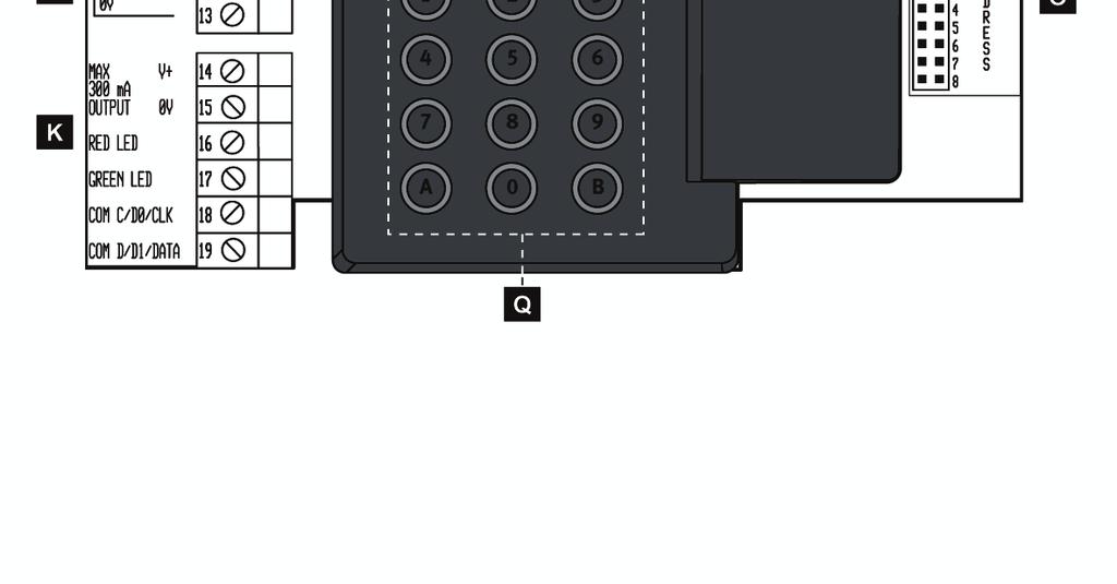
15 Wiring A. Lock to be opened with supplied special key. B. The corner details can be lifted and are prepared with knockouts used for sealing or hiding cable entry. The position of them should however remain (due to mechanical differences). They are numbered like this: (B1) = Lower left corner (B2) = Upper left corner. C. The box is fastened on the wall with four screws. Brackets are supplied to allow for using glands M12x1.5 (these are not included). If glands shall be used the default washers have to be removed. See picture on next page. D. The cables can either be safely mounted (cable goes over the edge) - or via knockouts in the same edge. Prepared with fixing details for securing the cables with cable ties. E. Power in: Terminal block nos. 1 and V DC or 8-28V AC F. Opening relay. Voltage free contacts. Maximum load 2 A. G Relay for Warning, Monostable Alarm by-pass, Alert or Duress. Software controlled. When Alert is selected also the tamper switch will activate this relay. H RS485 connection for system communication Com A & Com B to USB-RIF/2 (Entro Lite), next DC800 or SR34i (Entro). I. Input for door monitor contact. Indicates open or closed door. J. Remote opening input. For connection of an exit request button (push to make). K. Connection of card reader/keypad. Maximum load 300 ma. Maximum distance for BC-Link readers 100 m (dependant on cabling). Maximum distance for Clock & Data readers, e.g. proximity reader: 50 m L. Jumper for output voltage selection to reader/keypad +5V or Vin = incoming supply. Warning! Make sure the setting is correct, otherwise readers may be damaged. Default: +5V. M. Jumper for interface selection - CLOCK & DATA, BC-Link or Wiegand (26bit, 32bit or 8bit PIN code. Default: BC-Link. N. Jumper for system configuration - Stand-Alone, Entro Lite or Entro. Default: Stand-Alone. O. Jumper for address selection 1-8 for Entro Lite or Entro. Default: Address 1. P. Tamper switch. Gives warning if the DC800 controller s lid is opened. Note! Will also activate the relay in item G when this is setup as Alert. Q. Keypad 0-9 plus A & B to program the DC800. R. The LEDs red, yellow & green (together with the buzzer) indicates the different steps in the programming sequences. When the DC800 is in idle mode, the green LED will flash with approx. 5 seconds interval to verify that the DC800 is powered. 15
16 Wiring 4.1 Using cable glands In some cases it is desired to secure the cables via glands. The housing allows for using glands of M12 dimension (12 mm). When the DC800 is shipped there are washers mounted at the screw holes to allow for different kind of screw types when fixing it to e g a wall (see item C in the picture). If glands instead shall be used, proceed like below: 1. Remove the default washer(s). 2. Place the gland bracket(s) (on the little location pin) to decide which knockout to cut out. There are two different positions of he bracket. 3. Cut out approx mm and mount the supplied gland bracket(s). 4. Place the gland in the big hole of the bracket and fix it with the nut. 5. The cable is then mounted through the outer sleeve and connected to the desired terminal blocks on the PCB. 6. Optionally fix the cable even further using cable ties and then fix the sleeve. In the picture below is shown how to mount the gland bracket. NOTE The glands are not supplied with the housing (only the brackets). 16
17 Programming 5 Programming In the sections below are the instructions on how to program the DC800 controller. To be able to program DC800 you have to set the reader controller to programming mode. This is done by entering a six-digit code (password). Although the DC800 should be shipped with default settings, we recommended reading and proceeding according to the chapter Erase the Memory to ensure that the unit is erased before any programming take place. The six-digit code (password) is initially Buzzer and LEDs During programming you will be guided by the buzzer and the LEDs. In this manual the LEDs are illustrated in the following way: = OFF = Lit = Flashes In programming mode before a function is chosen: During programming: Correct programming: Faulty programming: All three LEDs are flashing. The LEDs are lit or OFF depending on the function Confirmed by a rising signal consisting of two quick beeps. Confirmed by a falling signal consisting of one long and one short beep. See also troubleshooting at the end of this manual. NOTE If, having entered programming mode, no key is pressed within 60 seconds; the unit will leave programming mode Using the reader for programming If you have a BC43 (with keypad) you can optionally use this or the DC800 for programming. If only the DC800 shall be allowed for programming, it is possible to inhibit the alternative with BC43. See chapter Programming barring. 17
18 Programming 5.2 Set DC800 to programming mode To program a function, the controller has to be in the programming mode. All programming is done from the controller s or the card reader s keypad. 1. Press B. 2. Enter the 6-digit password. The reader controller is now in programming mode. NOTE If the wrong password is entered twice in succession, the reader controller is blocked from further attempts for 40 seconds. 5.3 Set time and date 2. Press A Enter the current year, month and date, e.g for the 21st of September Enter the current day of the week. Example: 1 = Monday, 2 = Tuesday etc. 5. Enter the current time, e.g for one minute past 4 PM DC800 automatically goes back to programming mode. 5.4 Changing the password 2. Press A Enter the new password. A warning tone is heard. 4. Enter the new password again. The warning tone sounds until all six digits have been entered. 18
19 Programming 5.5 Program time zones This function is used to program up to eighty time zones to be used in the installation. 1. Take out the completed Time zone chart/s. 2. Set DC800 to programming mode. 3. Press A Enter the number of the time zone to be programmed. Use two digits, e.g. 01 for time zone Enter the starting time of the first time interval using four digits, e.g for 8 AM. 6. Enter the finishing time of the first time interval using four digits, e.g for PM. If there is no need for a second time interval, press A to skip and go to step Enter the start time of the second time interval using four digits, e.g for 1 PM. 8. Enter the stop time of the second time interval using four digits, e.g for 4.59 PM. 9. Enter the desired day type/s for this time zone. 10. Press B and go to step 4 to program another time zone or press B twice to go back to programming mode. 5.6 Erase a time zone 2. Press A Enter the number of the time zone to be erased. 4. Press A. 5.7 Program time schedules This function is used to program up to ten time schedules to be used in the installation. 1. Take out the completed Time schedule chart/s. 2. Set DC800 to programming mode. 3. Press A Enter the number of the time schedule to be programmed. Use two digits, e.g. 01 for time schedule Enter the time zones (maximum 8) to be included in the time schedule. Example: To include time zones 1, 2 and 4, enter Press B and go to step 4 to program another time schedule or press B twice to go back to programming mode. NOTE Remember that if you unintentionally program overlapping time schedules (used for the security levels) the highest security level apply in the following order: Closed Door, Card+PIN, Card, Group code and Unlocked. 19
20 Programming 5.8 Erase a time schedule 2. Press A Enter the number of the time schedule to be erased. 4. Press A. 5.9 Program holidays This function is used to pre-program holidays that do not occur on Sundays and holiday periods. The total number of holidays and/or holiday periods are Press A Enter the number of the holiday using two digits (01-15). 4. Enter the date of the holiday, e.g for the 24th of December. 5. If you program only one holiday, press 01. If a holiday period is being programmed, enter the duration in days of the period (with two digits), including the starting date. 6. Enter the day type to apply for this holiday/holiday period, e.g. 7 for Sunday. 7. Follow steps 3-6 to enter a new holiday/holiday period or press B to go back to programming mode Delete individual holidays This function is used to delete individual holidays, as distinct to deleting all programmed holidays (see the next section). 2. Press A Enter the number of the holiday, e.g Press B to go back to programming mode Delete all holidays This function is used to delete all programmed holidays. 2. Press A Press A55 one more time. DC800 automatically goes back to programming mode. 20
21 Programming 5.12 Programme/change/erase group code This is how to program a group code. You can program a maximum of 10 group codes. Remember that the security level must be set (command A34) to work at the same time as the group codes. Otherwise the group codes will not work. In the opposite way different time schedules (for group codes) can be used to disable when group codes shall work. E g if the security level is Group code, one code can work daytime and another in the nighttime. Note that the security level Group code also allow for users (by convenience) to use valid access cards to enter a door. That is both 4-digit codes and cards can be used in parallel. 2. Press A Enter to which time schedule the code should belong. Use 2 digits, e.g. 01 for time schedule Enter a four-digit group code. The existing code, if any, will be over-written. To erase the group code from a time schedule, enter To programme, change or erase another group code, follow steps Press B to leave programming mode Set time schedule Door unlocked 2. Press A Enter the number of the time schedule to control the Door unlocked security level. Use two digits, e.g. 01 for time schedule 1. To remove a time schedule from this security level, enter 00 in step 3 instead. 4. DC800 automatically go back to programming mode. Press B to leave the programming mode Set time schedule Group code 2. Press A Enter the number of the time schedule to control the Group code security level. Use two digits, e.g. 01 for time schedule 1. To remove a time schedule from this security level, enter 00 in step 3 instead. 4. DC800 automatically go back to programming mode. Press B to leave the programming mode. 21
22 Programming 5.15 Set time schedule Card Only 2. Press A Enter the number of the time schedule to control the Card only security level. Use two digits, e.g. 01 for time schedule 1. To remove a time schedule from this security level, enter 00 in step 3 instead. 4. DC800 automatically go back to programming mode. Press B to leave the programming mode Set time schedule Card + PIN 2. Press A Enter the number of the time schedule to control the Card+PIN security level. Use two digits, e.g. 01 for time schedule 1. To remove a time schedule from this security level, enter 00 in step 3 instead. 4. DC800 automatically go back to programming mode. Press B to leave the programming mode Set time schedule Toggle 2. Press A Enter the number of the time schedule to control the Toggle security level. Use two digits, e.g. 01 for time schedule 1. To remove a time schedule from this security level, enter 00 in step 3 instead. 4. DC800 automatically go back to programming mode. Press B to leave the programming mode Log on a card (with a card) Using this function, the cards to be used are programmed 1. Set DC800 to programming mode 2. Press A Enter the time schedule during which the card/s should be valid. Use 2 digits, e.g. 01 for time schedule Use the card at the reader. If several cards should be valid during the same time schedule, use these cards as well. 5. When finished, press B to go back to programming mode. 6. Press B one more time to leave programming mode. 22
23 Programming 5.19 Log on a card (without the card) Using this function, cards can be programmed by keying in the card number. 2. Press A Enter the time schedule during which the card/s should be valid. Use 2 digits, e.g. 01 for time schedule Enter the card number on the keypad. 5. If several cards should be valid during the same time schedule, use these cards as well. 6. When finished, press B to go back to programming mode. 7. Press B one more time to leave programming mode Log on a series of cards Using this function you can quickly log on a contiguous series of cards 2. Press A Enter the time schedule during which the cards should be valid. Use 2 digits, e.g. 01 for time schedule Enter the card number of the first card (8 digits) in the series. 5. Enter the card number of the last card (8 digits) in the series. If the programming is done at the card reader (with keypad) the yellow LED lit all the time as the cards are logged on. If the programming is made at the controller the buzzer in the controller will sound instead. It takes approximately 30 seconds to log on 100 cards cards takes approximately four and a half minutes. 6. Press B to leave programming mode Cancel card (with card) Using this function a card can be cancelled (with the card) so that it cannot be used in the card reader. 1. Set DC800 to programming mode 2. Press A Use the card at the reader. If several cards should be valid during the same time schedule, use these cards as well. 4. When finished, press B to go back to programming mode. 5. Press B one more time to leave programming mode. 23
24 Programming 5.22 Cancel card (without card) Using this function, cards can be cancelled using the card number. 2. Press A Enter the card number. If the card is not logged on the faulty programming signal is heard. 4. Cancel the next card, as required. 5. When finished, press B to go back to programming mode. 6. Press B one more time to leave programming mode Bank Lobby Function Using this function, DC800 can be programmed so mag stripe cards of a certain type, e.g. credit cards, can be used for entrance. Up to 15 prefixes can be programmed. Note that simultaneously it is possible to use cards programmed with the commands A01, A03 or A04. Proceed like this: 2. Press A Enter the identity of the prefix (01-15). 4. Enter from which position in the card number (01-40) the digits should be read. To remove an existing prefix, enter Enter which digits (maximum 7) to be read. Press A in the desired place to enter a wild card digit. E g 12A0. 6. Press B to end the command and B to leave programming mode. Example: If you set start position to 5 and the prefix to 12A0, all cards with 1200, 1210, 1220, 1230, 1240, 1250, 1260, 1270, 1280 and 1290 from position 5, will work. NOTE 1 The Bank Lobby Function will only work with Clock & Data mag stripe readers (which read all characters on the card). E g BC18 and BC16 (UK only). NOTE 2 If Bank Lobby Function is used, do not forget to set security level to Card only (command A35), with e.g. time schedule 01 (24 hours, all days). 24
25 Special settings 6 Special settings 6.1 Card reading parameters When DC800 is delivered, the card reader reads positions 9 to 16 on the card, or the last 8 positions if they are fewer than 16. If you want to use your own cards and they should be read differently, enter from which position on the reader should start reading and how many digits should be read (minimum 1, maximum 8). NOTE Previously logged on cards will not work if you change the card parameters. 2. Press A Enter from which digit in the card number (01-40) the digits should be read. 4. To reset this function to the default setting, press A at this point. 5. Enter the number of digits to be read (1-8). 6. Press B to leave programming mode. NOTE If less than 8 digits are used in the card number, add as many 0 digits as necessary to make up an eight-digit card number when using the A03, A04 and A16 commands. Example: If the card number is 5432, enter when using the A03, A04 and A16 commands. 6.2 Set door release time The door release time determines for how long the lock should remain released following a correct transaction. The default value is 7 seconds. This is how to change the opening time, if required: 2. Press A Enter the desired door release time (between 01 and 99 seconds). 4. DC800 automatically go back to programming mode. Press B to leave the programming mode. 25
26 Special settings 6.3 Set door held warning time If the door is still open when the door release time is over, a buzzer sounds at the door for the time set as door held warning time. The buzzer reminds the person entering to close the door immediately as an alarm is about to go OFF. This is how to change the door held warning time, if required: 2. Press A Enter the desired door held warning time (between 01 and 99 seconds). 4. DC800 automatically go back to programming mode. Press B to leave the programming mode. 6.4 Buzzer ON/OFF The default is that the buzzer is activated. If you do not want the buzzer to beep on key presses or door opening, it can be turned OFF. Note that even when the buzzer is OFF for normal operation, it will continue to sound during programming. 2. Press A Press Press B to leave programming mode. To reactivate the buzzer, press 1 in step 3 instead. 6.5 Door monitor contacts ON/OFF If door monitor contacts are used and this function is activated, a warning signal sounds during the time set as door held warning time, i.e. when the opening time has expired and the door is still open. This is how to make the settings: 2. Press A Press any of the following: 0 = door contacts deactivated 1 = door contacts activated, normal 2 = door contacts activated, magnetic locks 4. Press B to leave programming mode. 26
27 Special settings 6.6 Function for extra relay In the DC800 there exists an extra relay to be used for three different functions: Warning, Alert, Monostable Alarm by-pass or Duress. The diagram shows the function of the relay with different setup. Note that only one of the settings is possible. 1 Extra relay used as Warning (Option 1) 2. Extra relay used as Alert + Tamper (Option 2) 3. Extra relay used as Monostable alarm by-pass (Option 3) 4. Extra relay used as Duress (Option 4) 5. Unlocking relay 6. Door opened by User. Monitored by door contact. 7. Maximum Opening time. Monitored by door contact. 8. Door Held Warning Time (maximum) Warning: Alert + Tamper: Access is granted and the door is opened (monitor contact breaks). If door is still open after Opening Time, the relay changes over and remains until door is closed. Access is granted and the door is opened (monitor contact breaks). If door is still open after Door Held Warning Time, the relay changes over and remains until door is closed. Note that this selection will also allow the tamper switch to control the relay. If the lid is opened the (tamper switch breaks) - the relay changes over and remains until the lid is closed. Monostable: The relay changes over and remains during both the Opening Time and the Door Held Warning Time. Will return automatically if the door is closed during these periods. This can be used for by-passing an intruder alarm system (Monostable mode). Duress: If the security level is Card+PIN, the user can (when threatened)) raise the last digit in the PIN-code (1 to 2, 0 to 9 etc.). A 5 second long pulse is generated on the relay output (besides unlocking the door). The duress signal can be sent to an external alarm system for further action. Proceed like this to select the function: 2. Press A Press one of the following: 1 = Warning function (default) 2 = Alert + Tamper. 3 = Monostable. 4 = Duress. 4. Press B to leave programming mode. 27

28 Special settings 6.7 Anti pass-back Anti pass-back only works with card readers of the BC-Link type, where the reader can be set to be an entry or exit reader. This is how to activate anti pass-back: 2. Press A Press To deactivate anti pass-back, press Press B to leave programming mode. 6.8 Calculated PIN If it is preferred not to have the users choose their own PIN codes, this function will enable automatic calculation of PIN codes, based on the card holder s card number. Proceed as follows: 2. Press A Enter a 4-digit calculation factor. 4. Press B to leave programming mode. To disable the function, enter 0000 in step 3. The calculation factor is added to the last four digits in the card number. Example: If the card number is and the calculation factor is 4567, the code will be = All the extra result (1) is disregarded. 28
29 Special settings 6.9 Programming barring Another way to increase security is to enable programming barring, which means that programming can only be done in the controller not on the card reader. NOTE Remember that if the barring is enabled any card have to be logged on or cancelled using the digits of the cards. See commands A03, A04 or A14. This is how to enable programming barring: 2. Press A Press Press B to leave programming mode. To disable barring, press 0 in step Erase the memory Factory settings: When the reader controller s memory is erased, the default settings are restored (see below). 1. Open the lid of the controller with the supplied keys. 2. Press B. 3. Press Press once again. All previously entered data have now been erased. The reader controller reverts to the following settings: Password: Programming barring: OFF (0) Buzzer: ON (1) Door monitor contacts: OFF (0) Extra relay: Warning (1) Anti pass-back: OFF (0) Group code: None Opening time: 7 seconds Door Held Warning 10 seconds Time: Card parameters: Position 9-16, the last 8 positions if fewer than 16 positions. Bank Lobby Function None Time zone 01: 00:00 23:59, day types 1-7 Time schedule 01: Time zone 01 Security level: Group code 29
30 Programming overview 7 Programming overview Always start with B + password (the three LEDs are flashing). Exit with B. Start Command Step 1 Step 2 Step 3 Set time and date Press A23 Enter current date (YYMMDD) Enter current day type (1-7) Enter current time (HHMM) Time zones Program time zones Press A31 Enter time zone no (01-80) Enter start time for 1st interval (HHMM) Enter stop time for 1st interval (HHMM) Erase time zones Press A31 Enter time zone no (01-80) Press A. Returns to progr. mode Time schedules Program time schedules Press A32 Enter time schedule no (01-10) Enter time zone no/s included Press B to confirm input Erase time schedules Press A32 Enter time schedule no (01-10) Press A. Returns to progr. mode Step 4 Returns to progr. mode Enter start time for 2nd interval (HHMM) OR press A to skip to step 6 To step 1 OR B to progr. Mode. Step 5 Enter stop time for 2nd interval (HHMM) Step 6 Enter day type/s (1-8) Step 7 Press B to confirm input Step 8 To step 1 OR B to progr. Mode. 30
31 Programming overview Always start with B + password (the three LEDs are flashing). Exit with B. Security levels Command Step 1 Set time schedule using the Open security level Press A33 Enter time schedule no (01 10) Set time schedule using the Group code security level Press A34 Enter time schedule no (01 10) Set time schedule using the Card only security level Press A35 Enter time schedule no (01 10) Set time schedule using the Card+PIN security level Press A36 Enter time schedule no (01 10) Set time schedule using the Toggle security level Press A37 Enter time schedule no (01 10) Group code Programme/change group code Press A21 Enter time schedule no (01 10) Erase group code Press A21 Enter time schedule no (01 10) Step 2 Returns to progr. mode Returns to progr. mode Returns to progr. mode Returns to progr. mode Returns to progr. mode Enter group code Press 0000 Step 3 To step 1 OR B to progr. Mode. To step 1 OR B to progr. Mode. Step 4 Step 5 31
32 Programming overview Always start with B + password (the three LEDs are flashing). Exit with B. Cards Command Step 1 Log on card with card Press A01 Enter time schedule no (01-10) Log on card without card Press A03 Enter time schedule no (01-10) Log on a series of cards Press A04 Enter time schedule no (01-10) Cancel card with card Press A14 Use card Cancel card without card Press A16 Enter card number (8 digits) Bank Lobby Function Press A98 Enter prefix id (01-15) Holidays/holiday period Program holidays/holiday periods Press A51 Enter no for holidays/holiday periods (01-15) Delete individual holidays/holiday periods Press A52 Enter no for holidays/holiday periods (01-15) Delete all holidays/holiday periods Press A55 Press A55 once again Step 2 Use card Enter card number (8 digits) Enter first card number in the series (8 digits) To step 1 OR B to progr. Mode. To step 1 OR B to progr. Mode. Enter start position (01-40) Enter date (MMDD) To step 1 OR B to progr. Mode. Returns to progr. mode Step 3 To step 1 OR B to progr. Mode. To step 1 OR B to progr. Mode. Enter last card number in the series (8 digits) Enter digits (max 7). Enter A for wildcard Enter no of days including start date, e.g. 01 Step 4 Returns to progr. mode Returns to progr. mode Enter day type (1-8) Step 5 To step 1 OR B to progr. Mode. 32
33 Programming overview Always start with B + password (the three LEDs are flashing). Exit with B. Other functions Command Step 1 Set door opening time Press A28 Enter no of seconds (01-99) Set door held warning time Press A29 Enter no of seconds (01-99) Press A66 0 = OFF Door monitor contacts 1 = ON, normal 2 = ON, magnetic lock Press A68 1 = Warning 2 = Alert Warning/Alert/Monostable/Duress 3 = Monostable 4 = Duress Buzzer ON/OFF Press A65 1 = Buzzer ON 0 = Buzzer OFF Calculated PIN Press A24 Enter a 4-digit calculation factor Program Barring Press A25 0 = OFF 1 = ON Card reading parameters Press A97 Enter start position (01-40) Change password Press A27 Enter new password (6 digits) Anti pass-back Press A63 0 = OFF 1 = ON Erase memory Press Press once again Step 2 Returns to progr. mode Returns to progr. mode Returns to progr. mode Returns to progr. mode Returns to progr. mode Returns to progr. mode Returns to progr. mode Enter no of positions to be read (1-8) Enter new password once again Returns to progr. mode Returns to progr. mode Step 3 Returns to progr. mode Returns to progr. mode Step 4 33
34 Daily use 8 Daily use To open the door the user should do either of the following: Enter a four-digit group code (if Group code is the current security level). If the wrong group code is entered three times in succession, group code is blocked. To release the blockage, enter the correct group code twice in succession. Use a card/tag (if Card only or Group code is the current security level). Use a card and enter a personal code belonging to the card (if Card + PIN is the current security level). Should the wrong PIN-code be entered 3 times in succession, the card is automatically cancelled and must be logged on once again. 8.1 The toggle function If the toggle function is activated, the user can open the door in one of the abovementioned ways (depending on the current security level). The door remains open until a user (need not be the same one as opened the door) again completes a valid transaction or until another security level starts. 8.2 Choose/change PIN code To choose/change your individual PIN. NOTE If Calculated PIN is used, this function does not work. 1. Press A on the reader controller s keypad. 2. Use your card at the reader. 3. If it is the first time you are setting a PIN code for this card, enter Otherwise enter the existing code. 4. Enter the new code using four digits. 5. Enter the new code again. 6. The card is ready to use. 8.3 Duress This is what the cardholder should do to activate a duress alarm if forced to open the door under threat: 1. Use the card (as usual). 2. Enter the usual PIN, only add 1 to the last digit in the PIN-code. Example 1: If the PIN is 1234, press 1235 instead. Example 2: If the PIN is 1239, press 1230 instead! When a duress code is entered, the door is unlocked at the same time as the extra relay is activated for 5 seconds. 34
35 Troubleshooting 9 Troubleshooting Problem Possible cause Action Cannot enter programming Wrong password. Choose a new password. mode. Red LED is lit after two trials. Green LED is lit on accepted entrance but the door does not open Lock error. Check cable between reader controller and lock. Change locks. A card is used at the card reader but nothing happens. No beep is heard. A card is used at the reader, a beep is heard, but nothing happens. The magnetic reader head is loose. The magnetic reader head is dirty. The reader head is not working. The card is not logged on. Wrong time. Tighten the reader head. Clean the reader head using a special cleaning card. Check the cabling. Change card reader or reader head. Log on the card. Check time schedules and/or set calendar clock. The card does not work with PIN-code. Card only works when Card+PIN should apply. Group code does not work. The Door monitor function does work properly. Three wrong PIN in succession and the card is blocked. No PIN-code have been chosen for the card. Wrong time schedule and/or security level. Security level Group code not programmed. The function wrongly programmed. The function chosen but incorrect cable connection. Log on the card again and choose enter the correct PIN. Program unique PIN-codes at reader - or use calculated PIN (A24). Check that the security level Card+PIN have been programmed correctly. Both the code and the Security level must be programmed (A21 & A34). Program Door monitor function (A66) correct. Check cables and program function correct. 35
36 Technical specification 10 Technical specification Power supply: V DC, 8-28 V AC Power consumption: Maximum 200 ma (24Vdc) excluding reader. Relay outputs: Opening relay: Maximum 2A, 30 V DC Extra relay: Maximum 2A, 30 V DC Inputs: Normally pulled high. Active when pulled low, i.e. 0 V. Interface: RS485 connection To PC (via USB RIF/2) To next DC800 To SiPass Entro Segment controller Temperature range: -35 C to +50 C, at 90 % air humidity Dimensions (WxHxD) mm: 250 x 128 x 54 36
37 Charts 11 Charts 11.1 Time zones No (01-80) Name 1st interval From To 2nd interval From To Day type/s Example: No (01-80) Name 1st interval From To 2nd interval From To Day type/s 01 Working Hours
38 Charts 11.2 Time schedules No Name Time zones included Example: No Name Time zones included 01 Office Staff Security levels Level Door unlocked Group code Card only Card + PIN Toggle Time schedules 11.4 Group Codes Name Time schedule Group code 38
39 Charts 11.5 Special settings Function Setting Default setting Password Opening time 7 sec Door Held Warning 10 sec Time Function extra relay 2 Warning (1) Alert (2) Warning (1) Monostable (3) Duress (4) Buzzer OFF (0) ON (1) ON Door monitor contact OFF (0) ON (1), normal OFF ON (2), magnetic lock Anti pass-back OFF (0) ON (1) OFF 11.6 Prefix Bank Lobby Function Prefix ID Start position Digits with/without joker A (max 7) Example: A0 Means that all cards 5700, 5710, 5720, 5730, 5740, 5750, 5760, 5770, 5780, 5790 in position will be accepted. 39
40 Charts 11.7 Holidays/Holiday periods No Date (MMDD) Duration in days Day type Example: No Date (MMDD) Duration in days Day type
41 Charts 11.8 Persons Name Card number Time schedule Example: Name Card number Time schedule Smith Willie
42 Issued by Bewator AB SE Solna Sweden Copyright by Bewator AB, a Siemens company Data and design subject to change without notice. Supply subject to availability. Document no. A24205-A335-B329 Edition
ACT 10 Digital Keypad Operating & Installation Instructions This manual is found at
 ACT 10 Digital Keypad Operating & Installation Instructions 18-00001 This manual is found at www.eaglesecuritysolutions.co.uk Installation Notes Always remember to factory default the controller before
FlexiScan. Impro FlexiScan 4-Channel Controller INSTALLATION MANUAL
 MODEL NUMBER: HCM991-0-0-GB-XX FlexiScan SPECIFICATIONS Impro FlexiScan 4-Channel Controller INSTALLATION MANUAL Working Environment... Security... Input Voltage... The Impro FlexiScan is designed to work
Access Control Keypad for MK-DV, JB-DV
 #91173 0406 Access Control Keypad for MK-DV, JB-DV - INSTRUCTIONS - The KVI is a surface mount electronic access control keypad for use with Aiphone s MK-DV or JB-DV video door station. Designed with the
SCS318. User Instructions. SCS318 comprising of SCS317 7 Day Wireless Programmable Room Thermostat and SSR303 Receiver
 SCS318 User Instructions SCS318 comprising of SCS317 7 Day Wireless Programmable Room Thermostat and SSR303 Receiver Programmable room thermostats are widely recognised as one of the best ways in which
SPX-5600 Series. Operations Manual. Suprex Reader Extender - RF Wireless Interface SPX-5600MAN. Page 1 of 20
 SPX-5600 Series Operations Manual Suprex Reader Extender - RF Wireless Interface SPX-5600MAN Page 1 of 20 SPX-5600 Series: Cypress Suprex SPX-5600 Series This manual covers the operation and setup of the
OPERATION AND MAINTENANCE
 BAS MS/TP Enabled OPERATION AND MAINTENANCE An Company Contents Powering Up For The First Time... 3 Setting MSTP Communication Parameters... 4 Changing the MSTP Address... 4 Changing the BACNET ID... 5
M150SP USER S AND INSTALLER S MANUAL. v2.0 REV. 03/2017
 M150SP USER S AND INSTALLER S MANUAL v2.0 REV. 03/2017 00. CONTT 01. SAFETY INSTRUCTIONS INDEX 01. SAFETY INSTRUCTIONS STANDARDS TO FOLLOW 02. THE DEVICE TECHNICAL SPECIFICATIONS VISUAL ASPECT CONNECTORS
Weekly Timer. Mounting track 50 cm (1.64 ft) length PFP-50N 1 m (3.28 ft) length PFP-100N
 length PFP-50N 1 m (3.28 ft) length PFP-100N") Weekly Timer 1/4 DIN Size Timer Features Prompted Programming and Large LCD Display 24 hours x 7 days programming using just 5 switches 16 program steps and cycle operation Two independent 15 A control
Weekly Timer 1/4 DIN Size Timer Features Prompted Programming and Large LCD Display 24 hours x 7 days programming using just 5 switches 16 program steps and cycle operation Two independent 15 A control
Automatic Transfer Switch Control PLC Operator s Manual
 MTS Power Products MIAMI FL 33142 ATS-22AG Automatic Transfer Switch Control PLC Operator s Manual Dedicated Single Phase Transfer Switch ATS-22AG Automatic Transfer Switch INTRODUCTION 1.1 Preliminary
FN:4181M5.DOC MC4181N SERIES MASTER CLOCKS MC4181N
 FN:4181M5.DOC MC4181N SERIES MASTER CLOCKS MC4181N TABLE OF CONTENTS 1.0 INTRODUCTION 2.0 SPECIFICATIONS 3.0 INSTALLATION 4.0 GETTING STARTED 4.1 The Auto-Prompt Display 4.2 The Cursor, Entering Data 4.3
Thank you for purchasing this product. If installing for someone else, please ensure that the instructions are handed to the householder.
 Instruction Manual TPSE201 (181422) - BOSS TM Universal Programmer TPSE101 (569565) - BOSS TM Universal Timeswitch Thank you for purchasing this product. If installing for someone else, please ensure that
USER S GUIDE. 1 Description PROGRAMMABLE 3-RELAY LOGIC MODULE
 1 Description The is a programmable 3 relay logic module that may be used for multiple applications, including simple timing, door mounted sensor inhibiting and advanced relay sequencing. The contains
TORK DGU100/DGUM100 7 DAY DIGITAL TIME SWITCH INSTALLATION AND OPERATING INSTRUCTIONS READ INSTRUCTIONS CAREFULLY BEFORE SETTING UNIT
 TORK DGU100/DGUM100 7 DAY DIGITAL TIME SWITCH INSTALLATION AND OPERATING INSTRUCTIONS READ INSTRUCTIONS CAREFULLY BEFORE SETTING UNIT INSTALLATION UNIT IS TO BE INSTALLED BY A LICENSED ELECTRICIAN 1. To
Using the More Advanced Features of the AUTOcard-SA System
 Using the More Advanced Features of the AUTOcard-SA System IMPORTANT NOTICE This manual describes the AUTOcard-SA system s more advanced features. If you wish to only program the system s basic features
Provides an activation of Relay 1 triggered by Input 1. The function also provides an option for reverse-logic on the activation of Input 1.
 USER S GUIDE PROGRAMMABLE 3-RELAY LOGIC MODULE 1 Description The is a programmable 3 relay logic module that may be used for multiple applications, including simple timing, door mounted sensor inhibiting
7 Day Digital Programmer 3 Channel Surface Mount
 7 Day Digital Programmer 3 Channel Surface Mount Model: TRT038N Installation & Operating Instructions 1. General Information These instructions should be read carefully and retained for further reference
FN:4181NX_M1.DOC MC4181NX MASTER CLOCK MC4181NX
 FN:4181NX_M1.DOC MC4181NX MASTER CLOCK MC4181NX TABLE OF CONTENTS 1.0 INTRODUCTION 2.0 SPECIFICATIONS 3.0 INSTALLATION 4.0 GETTING STARTED 4.1 The Auto-Prompt Display 4.2 The Cursor, Entering Data 4.3
Installation and User Guide 458/CTR8 8-Channel Ballast Controller Module
 Installation and User Guide 458/CTR8 8-Channel Ballast Controller Module Helvar Data is subject to change without notice. www.helvar.com i Contents Section Page Introduction 1 Installation 2 1. Attach
USER & ENGINEER INSTRUCTION MANUAL
 USER & ENGINEER INSTRUCTION MANUAL BENSON CP4 USER INSTRUCTIONS CONTENTS PAGE SUBJECT PAGE No. Contents Page... 1 CP4 Basic Setting Guide... 2-3 Standard Terms... 4 Normal RUN Mode... 4 Override... 5
SBL /SBLG Series Wireless Clock
 Installation Manual V8.3 SBL /SBLG Series Wireless Clock Current as of August 2018 The Sapling Company, Inc. SBL and SBLG Series Wireless Clocks Table of Contents Table of Contents 2 Important Safety Instructions
SINGLE ZONE CLIMATE ZONING SYSTEM. Technical Manual. Polyaire Pty Ltd
 SINGLE ZONE CLIMATE ZONING SYSTEM Technical Manual Polyaire Pty Ltd 11-13 White Road GEPPS CROSS South Australia, 5094 Tel: (08) 8349 8466 Fax: (08) 8349 8446 www.polyaire.com.au CONTENTS Features 1 Application
DTS400B - DZS400BP 3/9/07 10:14 AM Page 1
 DTS400B - DZS400BP 3/9/07 10:14 AM Page 1 18 DTS400B - DZS400BP 3/9/07 10:14 AM Page 3 TABLE OF CONTENTS Section Page Capabilities and Features.......... 1 Installation Instructions............ 2 Instructions
VLC-3 USER'S MANUAL. Light Program Controller. M rev. 04 K rev. 00 & ( ( 5, 352*5$0 1 : $ 2 ' 6(77,1*6 )81&7,216
81&7,216") Light Program Controller VLC-3 USER'S MANUAL +50,1 +50,1 1 : $ ' 2 7. 6 8 ' 5, 7 6 6. $ ( 3 352*5$0 0,16(& )81&7,216 6(77,1*6 & 8 5 5 ( 1 7 3 ( 5, 2 ' M 890-00189 rev. 04 K 895-00406 rev. 00 GENERAL...
Light Program Controller VLC-3 USER'S MANUAL +50,1 +50,1 1 : $ ' 2 7. 6 8 ' 5, 7 6 6. $ ( 3 352*5$0 0,16(& )81&7,216 6(77,1*6 & 8 5 5 ( 1 7 3 ( 5, 2 ' M 890-00189 rev. 04 K 895-00406 rev. 00 GENERAL...
REMOTE DISPLAY WIRELESS DECODER MK II
 REMOTE DISPLAY WIRELESS DECODER MK II INSTALLATION MANUAL Part No. LED-DEC 1. Contents 1. Contents... 1 2. Equipment List... 2 3. Overview... 2 Introduction... 2 Location Selection **Important **... 2
Manual. Simrad IS80 Heading Repeater HR80. English
 Manual Simrad IS80 Heading Repeater HR80 English www.simrad-yachting.com A brand by Navico - Leader in Marine Electronics Manual Simrad IS80 Heading Repeater HR80 English Document no: 20223194 Revision:
RA-RS232, RB-RS232. Setup and Installation Guide Addendum For RadioRA RS232 Interface
 RA-RS232, RB-RS232 Setup and Installation Guide Addendum For RadioRA RS232 Interface A Comprehensive Step-by-Step Guide for Programming and Operating the Lutron RadioRA RS232 Interface Note: Please leave
1/3 CMOS Ultra Wide Dynamic Color Camera CCWC1345-LX CCWC1345-MX
 1/3 CMOS Ultra Wide Dynamic Color Camera CCWC1345-LX CCWC1345-MX Configuration Manual Fire Safety & Security Products Liefermöglichkeiten und technische Änderungen vorbehalten. Data and design subject
XTM72E & F Real-Time Clock Modules
 Capricorn Controls Ltd Data & Application Notes Page 1 of 8 XTM72E & F Real-Time Clock Modules Originally designed to compliment our wide range of Gen-Set controls, these DC powered Real-Time-Clocks have
ImproX (TRT) Twin Remote Terminal INSTALLATION MANUAL
 Twin Remote Terminal INSTALLATION MANUAL") SPECIFICATIONS MODEL NUMBER: XRT910-0-0-GB-XX XRT911-0-0-GB-XX XTT911-0-0-NN-XX IMPROX TRT ImproX (TRT) Twin Remote Terminal INSTALLATION MANUAL Working Environment XRT910-0-0-GB-XX... (Aluminium Extruded
SPECIFICATIONS MODEL NUMBER: XRT910-0-0-GB-XX XRT911-0-0-GB-XX XTT911-0-0-NN-XX IMPROX TRT ImproX (TRT) Twin Remote Terminal INSTALLATION MANUAL Working Environment XRT910-0-0-GB-XX... (Aluminium Extruded
Timer Modules. MEU11 24 Hour Module, MEU17 7 Day Module (Without Housing)
") Timer Modules MEU11 24 Hour Module, MEU17 7 Day Module (Without Housing) EMU11 24 Hour Module, EMU17 7 Day Module (With Housing Giving panel mounting facility) Installation & Operating Instructions 1 1.
Timer Modules MEU11 24 Hour Module, MEU17 7 Day Module (Without Housing) EMU11 24 Hour Module, EMU17 7 Day Module (With Housing Giving panel mounting facility) Installation & Operating Instructions 1 1.
16 Amp Electronic 24 Hour/7 Day Time Controller
 16 Amp Electronic 24 Hour/7 Day Time Controller Model: ELU56 Installation & Operating Instructions 1 1. General Information These instructions should be read carefully and retained for further reference
Thank you for purchasing this product. If installing for someone else, please ensure that the instructions are handed to the householder.
 Instruction Manual TPST501 (569568) - BOSS TM Universal mable Room Thermostat (Wired) (7 day, 5/2 day and 24 hour programme options) Thank you for purchasing this product. If installing for someone else,
Quick Operation Guide of LTN7700/7600 Series NVR
 Quick Operation Guide of LTN7700/7600 Series NVR UD.6L0202B0042A02 Thank you for purchasing our product. If there is any question or request, please do not hesitate to contact dealer. This manual is applicable
Room thermostat Instructions for Use. For the user. Instructions for Use. geotherm
 Room thermostat Instructions for Use For the user Instructions for Use geotherm GB table of contents HOW TO USE YOUR APPLIANCE 1 Appliance use...2 1.1 Overall view... 2 1.2 Display... 2 1.3 Main screen...
SSPT724A Timer Quick Start Guide
 SSPT724A Timer Quick Start Guide Open timer enclosure and remove mounting parts and instructions. When ready to program the timer, plug in timer to 120 Volt Ac power receptacle Press the SET button to
Two (2) Channel 365 Day 24 Hr. Timer/Controllers
 Channel 365 Day 24 Hr. Timer/Controllers") Two (2) Channel 365 Day 24 Hr. Timer/Controllers Models include: PT2724 - Timer module PT2724E - Timer module in enclosure Installation Guide Rev. 020317 More than just power. TM Overview: Altronix PT2724/PT2724E
Two (2) Channel 365 Day 24 Hr. Timer/Controllers Models include: PT2724 - Timer module PT2724E - Timer module in enclosure Installation Guide Rev. 020317 More than just power. TM Overview: Altronix PT2724/PT2724E
Operations. BCU Operator Display BMTW-SVU02C-EN
 Operations BCU Operator Display BMTW-SVU02C-EN Operations BCU Operator Display Tracer Summit BMTW-SVU02C-EN June 2006 BCU Operator Display Operations This guide and the information in it are the property
RD RACK MOUNT DIMMER OWNERS MANUAL VERSION /09/2011
 RD - 122 RACK MOUNT DIMMER OWNERS MANUAL VERSION 1.3 03/09/2011 Page 2 of 14 TABLE OF CONTENTS UNIT DESCRIPTION AND FUNCTIONS 3 POWER REQUIREMENTS 3 INSTALLATION 3 PLACEMENT 3 POWER CONNECTIONS 3 OUTPUT
ComfortChoice Touch Thermostat. Designed for ZigBee R Wireless Technology USER GUIDE
 ComfortChoice Touch Thermostat Designed for ZigBee R Wireless Technology USER GUIDE TABLE OF CONTENTS PAGE WELCOME... 8,9 THE TOUCH SCREEN... 10,11 Home - Inactive... 10 Home - Active... 11 PHYSICAL BUTTONS...
TU-8A. 8 Channel Digital Timer Unit. Programming Guide
 TU-8A 8 Channel Digital Timer Unit Programming Guide Introduction Thank you for purchasing the TU-8A 8 Channel Digital Timer Unit. The TU-8A is a weekly event programmable timer providing 8 independent
Reference Manual. Notes 9/16 Series H
 Reference Manual Notes 9/16 Series 173.01H Copyright notice The information in this document is subject to change without prior notice and does not represent a commitment on the part of Q-MATIC AB. All
Overview: Specifications: Installation Instructions:
 Overview: The SignalGuys.com Start/Stop Work Timer PT724A is an extremely versatile 24 Hour 365 Day Event Timers designed to support a wide range of applications. Such applications include: Start/Stop
ivw-fd122 Video Wall Controller MODEL: ivw-fd122 Video Wall Controller Supports 2 x 2 Video Wall Array User Manual Page i Rev. 1.
 MODEL: ivw-fd122 Video Wall Controller Supports 2 x 2 Video Wall Array User Manual Rev. 1.01 Page i Copyright COPYRIGHT NOTICE The information in this document is subject to change without prior notice
2 CHANNEL RECEIVER DISPLAY POTENTIOMETER COM2 NC2 NO2
 2 CHANNEL RECEIVER RECTSHIVE915-DX Please read this manual carefully before installing the product. 1 DESCRIPTION Receiver Rolling Code, 2 channels with dry contact relay output 20A a 12 Vdc. Programming
PT Two (2) Channel 365 Day 24 Hr. Timer/Controller
 Channel 365 Day 24 Hr. Timer/Controller") PT2724 - Two (2) Channel 365 Day 24 Hr. Timer/Controller Overview: This unit is an extremely versatile two channel 365 Day 24 Hour Timer / Controller designed to support a wide range of applications. Such
PT2724 - Two (2) Channel 365 Day 24 Hr. Timer/Controller Overview: This unit is an extremely versatile two channel 365 Day 24 Hour Timer / Controller designed to support a wide range of applications. Such
Transponder Reader TR22A01KNX TR22A11KNX. Product Handbook
 Transponder Reader TR22A01KNX TR22A11KNX Product Handbook Product: Transponder Reader Order Code: TR22A01KNX - TR22A11KNX Application Program ETS: EEL_RDT1_10 Transponder Card Reader Pagina 1 di 24 Index
Weekly Time Switch. Rated time Time setting range Time division 24 hrs x 7 days 00:00 to 23:59 1min
 Weekly Time Switch Easy Programming with Large LCD Display and Interactive Functions Programming for 24 hrs x 7 days using just five switches. Sixteen program steps available. Power supply freely selectable
Component Video Matrix Switcher Series ITEM NO.: YS04MA, YS04MD
 Component Video Matrix Switcher Series ITEM NO.: YS04MA, YS04MD Our component video switcher allows four different component video and stereo/digital audio sources to share two video displays. Manage multiple
Sample BD Tech Concepts LLC
 XYZ Corp. Fry Controller FC-1234 Software Test Procedure Copyright 2014 Brian Dunn BD Tech Concepts LLC Last Modified: 00/00/0000 Version Tested: Date Tested: Technician: Results: 1 FC-1234 SW Test Proc.
Installation and Operation Manual. YMP Series Signal Programmer
 Installation and Operation Manual YMP Series Signal Programmer February 2006 YMP Series Clock/Signal Programmer Installation and Operation Manual YMP Series Clock/Signal Programmers YMP YMP02 YMP04 YMP06
Master Time Clock MTC Users Manual
 Master Time Clock MTC-6000 Users Manual Midwest Time Control Phone (972)987-4408 Toll Free (888)713-0373 FAX (877)720-9291 www.midwest-time.com sales@midwest-time.com TABLE OF CONTENTS TOPIC PAGE GENERAL
VNS2210 Amplifier & Controller Installation Guide
 VNS2210 Amplifier & Controller Installation Guide VNS2210 Amplifier & Controller Installation 1. Determine the installation location for the VNS2210 device. Consider the following when determining the
ET BLU MIX RX-Condo-3
 ET BLU MIX RX-Condo-3 Three channel, 999 user, enhanced rolling code receiver. Ver: 2016.10.001 Product identification: Dark blue base with light blue top casing. White and orange antenna. 3 digit 7 segment
WDK-2500-STROBE. User Guide
 WDK-2500-STROBE User Guide Warning: This device complies with Part 15 of the FCC rules, operation of this device is subject to the following conditions: 1. This device may not cause harmful interference.
TC-1 Timeclock. Operating and Programming Instructions Thursday, 25 March Lighting Controls for the World we live in
 TC-1 Timeclock Operating and Programming Instructions Thursday, 25 March 2010 The ilight TC1 Timeclock is used to automate a lighting control system, turning some of the lights on and off according to
TITLE BOX PAGE ONLY. DO NOT MAKE FILM DO NOT PRINT. MATERIAL: White 16lb (60g/m sq), uncoated, prefer recycled stock Ink: Black
, uncoated, prefer recycled stock Ink: Black") REV DESCRIPTION INT: REV. DATE APPROVED 1 ECO# C01429 MJS 9/7/05 CG 2 ECO# 02412 DR TITLE BOX PAGE ONLY. DO T MAKE FILM DO T PRINT MATERIAL: White 16lb (60g/m sq), uncoated, prefer recycled stock Ink:
REV DESCRIPTION INT: REV. DATE APPROVED 1 ECO# C01429 MJS 9/7/05 CG 2 ECO# 02412 DR TITLE BOX PAGE ONLY. DO T MAKE FILM DO T PRINT MATERIAL: White 16lb (60g/m sq), uncoated, prefer recycled stock Ink:
Model 1476-C SuperQuad HR
 Model 1476-C SuperQuad HR Installation and Operating Instructions Table of Contents Page Table of Content... 2 System Description... 3 Features... 3 Installation... 4 Internal Setups... 4 Connections...
VNS2200 Amplifier & Controller Installation Guide
 VNS2200 Amplifier & Controller Installation Guide VNS2200 Amplifier & Controller Installation 1. Determine the installation location for the VNS2200 device. Consider the following when determining the
Valcom Wired Digital Clock
 Installation Manual V10.5 Valcom Wired Digital Clock V-D11025B, V-D11040B, V-D2425B, V-D2440B, V-2425B-6, and V-D2440B-6 Current as of February 2017 Valcom, Inc. Valcom Digital Series 2-Wire and 3-Wire
Programming Guide and User Manual INS # Model # CKM. ControlKeeper M
 Programming Guide and User Manual Model # CKM INS # Contents Contents Description Contents....2 Safety Instructions....3 Introduction....4 Welcome....4 Terminology used in this guide....5 ControlKeeper
OPERATIONAL MANUAL EMZS CH Speaker Zone Selector. Version 1.6
 OPERATIONAL MANUAL EMZS-8012 12CH Speaker Zone Selector Version 1.6 1 Product Overview The EMZS-8012 is a 1U rack-mounting unit, provide 12 channel direct zone switching for single source public address
Timer Modules. EL11 24 Hour Module EL17 7 Day Module. Installation & Operating Instructions
 Timer Modules EL11 24 Hour Module EL17 7 Day Module Installation & Operating Instructions 1 1. General Information These instructions should be read carefully and retained for further reference and maintenance.
Softswitch128TM. SwitchingSystem. Setup and Maintenance Guide
 Softswitch128TM SwitchingSystem TM R Setup and Maintenance Guide Believeitornot,thisissupposed to look likeadictionary! Thisiconwascreated by BrentM.Nye,July 6,1995. Believeitornot,thisissupposed to look
A Motor can be in many groups, by assigning additional channel# on it.
 Timer Remote Control Instruction How to use the channel numbers - There are 32 channels on the Remote Control Timer you can assign to Curtain Motor(s). To operate the Motors individually by itself only,
A new generation of access control.
 TM A new generation of access control. 2 or 4 Door Expandable Controller INSTALLATION MANUAL Installation overview: Installation Diagram Switch Alpha 4 Alpha 4 + PoE Alpha 4 + PoE Alarm central Accessory
16-CH Color Full Duplex Multiplexer Instruction Manual
 16-CH Color Full Duplex Multiplexer Instruction Manual 707-V1.5(S) Index: 1. Safety Warning 3 2. Introduction 3 3. Features 4 4. Specification 5 5. Front Panel Keypad 6 6. Back Panel Connection 10 7. Menu
STX Stairs lighting controller.
 Stairs lighting controller STX-1795 The STX-1795 controller serves for a dynamic control of the lighting of stairs. The lighting is switched on for consecutive steps, upwards or downwards, depending on
Model IQ4-PC User Manual Revision Date:
 Basic Specifications Supply Volts 230V 50/60Hz ±15% 115V 50/60Hz ±15% 24V DC (isolated) ±15% Power Consumption Max. 3VA (IQ4-PC-R0) Max. 6VA (IQ4-PC-R2-PSI24-RT) Operating Temperature -5 ~ +60 C Operating
ivw-fd133 Video Wall Controller MODEL: ivw-fd133 Video Wall Controller Supports 3 x 3 and 2 x 2 Video Wall Array User Manual Page i Rev. 1.
 MODEL: ivw-fd133 Video Wall Controller Supports 3 x 3 and 2 x 2 Video Wall Array User Manual Rev. 1.01 Page i Copyright COPYRIGHT NOTICE The information in this document is subject to change without prior
RADIO RECEIVER RGBW CONTROLLING LED STRIP COMMON ANODE
 TELECO AUTOMATION SRL - Via dell Artigianato, 16-31014 Colle Umberto (TV) ITALY TELEPHONE: ++39.0438.388511 FAX: ++39.0438.388536 - www.telecoautomation.com This document is the property of Teleco Automation
Tech Support: Customer Service: General Tech Questions: Tech Docs:
 Tech Support: 1-800-407-4545 Customer Service: 1-800-523-2462 General Tech Questions: Tech_Services@beainc.com Tech Docs: www.beasensors.com BR3-X Programmable 3 Relay Advanced Logic Module & Restroom
DIGITAL TIME SWITCH 7 DAY WITH INPUT DGU100A DGUM100A DGLC100A DGLC200A
 INSTRUCTION MANUAL LISTED DIGITAL TIME SWITCH 7 DAY WITH INPUT DGU100A DGUM100A DGLC100A DGLC200A FOR TECHNICAL SUPPORT: 888.500.4598 A DIVISION OF NSi INDUSTRIES, LLC USA 800.321.5847 www.nsiindustries.com
SR - 516D DESK TOP DMX REMOTE STATION. Version: Date: 05/16/2013
 SR - 516D DESK TOP DMX REMOTE STATION Version: 1.10 Date: 05/16/2013 Page 2 of 10 TABLE OF CONTENTS DESCRIPTION 3 POWER REQUIREMENTS 3 INSTALLATION 3 CONNECTIONS 3 POWER CONNECTIONS 3 DMX CONNECTIONS 3
Softwired Clock. Total Lighting Control. Catalog Number: RCLK8SWS DESCRIPTION FEATURES. Installation Instructions IMRCLK8SWS 1
 Total Lighting Control Softwired Clock DESCRIPTION The Softwired Switching (SWS) System is a small network of relay panels and occupant control switches linked by a 4-wire dataline. Together these devices
VHF & UHF REMOTE RECEIVERS INSTALLATION AND PROGRAMMING INSTRUCTIONS MODEL NUMBERS TMP-5414 & TMP 5428
 VHF & UHF REMOTE RECEIVERS INSTALLATION AND PROGRAMMING INSTRUCTIONS MODEL NUMBERS TMP-5414 & TMP 5428 Table of Contents Section Page No 1. INTRODUCTION... 3 2. TOOLS & TEST EQUIPMENT... 4 3. RECEIVER
ALM-6813/6812 INSTALLATION AND PROGRAMMING MANUAL
 ALM-6813/6812 INSTALLATION AND PROGRAMMING MANUAL Installation and programming Manual v2.2 1 MARSS Solar Defender SYSTEM This guidebook provides the essential instructions to install and configure the
PREPAX DELUXE INTERCOM SYSTEMS
 PREPAX DELUXE INTERCOM SYSTEMS Thank you for investing in a PREPAX Deluxe model intercom system. Kindly make sure that the input voltage specifications are maintained and that no external voltage is applied
MARCO CORNER, 19/ THIENE (VI) ITALIA
 ITALIA") DECLARATION OF CONFORMITY KOLVER S.r.l. VIA MARCO CORNER, 19/21 36016 THIENE (VI) ITALIA Declare that the new machine here described: ACE Screw Counter Is in conformity with the following standards and
DECLARATION OF CONFORMITY KOLVER S.r.l. VIA MARCO CORNER, 19/21 36016 THIENE (VI) ITALIA Declare that the new machine here described: ACE Screw Counter Is in conformity with the following standards and
Projector Lift. User Guide INSTALLATION OPERATION SETUP PROGRAM IR REMOTE FACTORY RESET
 INSTALLATION OPERATION SETUP PROGRAM IR REMOTE FACTORY RESET MODELS: Small - Standard Deep - Wide - Large X-Large - XX-Large Projector Lift User Guide ver 26.01.012 2012 PureTheatre CONTENTS Part Checklist...
SECURITRON PRIME TIME MODEL DT-7 INSTALLATION AND OPERATING INSTRUCTIONS
 Securitron Magnalock orp. www.securitron.com ASSA ABLOY, the global leader Tel 800.624.5625 techsupport@securitron.com in door opening solutions SEURITRON PRIME TIME MODEL DT-7 INSTALLATION AND OPERATING
UHF REMOTE RECEIVER INSTALLATION & PROGRAMMING
 UHF REMOTE RECEIVER INSTALLATION & PROGRAMMING Table of Contents Section Page No INTRODUCTION... 3 TOOLS & TEST EQUIPMENT... 4 RECEIVER POSITION... 4 UHF REMOTE RECEIVER RELEVANT HIGH GAIN AERIALS... 4
User s Guide. Dimensions 4000 Series Control System. Topics at a Glance
 User s Guide Dimensions 4000 Series Control System Topics at a Glance Installation...See Installation Guide Quick Start Configuration...11 User Interface...8 Initial Setup...19 Scheduling...63 Scene Recording...54
1 Overview. 2 Specifications. 3 Installation Instructions. HPT724 Programmable LCD Timer PN 52765:A 1/25/06 ECN Product Installation Document
 Honeywell 12 Clintonville Road Northford, CT 06472 http://www.honeywellpower.com HPT724 Programmable LCD Timer PN 52765:A 1/25/06 ECN 05-637 1 Overview Product Installation Document The Honeywell HPT724
TeamWork Kits Installation Guide
 TX 0 RX COM +5V APARATUS US TeamWork Kits Installation Guide TeamWork 400 and TeamWork 600 Kits The TeamWork 400 and TeamWork 600 kits consist of an HDMI switcher, system controller, Cable Cubby, and cables
Installation Instructions
 SuperBus 2000 Concord 4 GSM Module 466-2262A October 2006 Copyright 2006, GE Security Inc. Introduction This is the GE SuperBus 2000 Concord 4 GSM Module Installation Instructions for part number 600-1053.
Troubleshooting. 1. Symptom: Status indicator (Red LED) on SSR is constant on. 2. Symptom: Output indicator (Yellow LED) on SSR is flashing.
 on SSR is constant on. 2. Symptom: Output indicator (Yellow LED) on SSR is flashing.") Product Data Electrical Data SST (Transmitter) SSR (Receiver) Supply voltage 18 30 V dc Max. Voltage ripple 15 % (within supply range) Current consumption 100 ma (RMS) 75 ma Digital - 100 ma Max. outputs
Product Data Electrical Data SST (Transmitter) SSR (Receiver) Supply voltage 18 30 V dc Max. Voltage ripple 15 % (within supply range) Current consumption 100 ma (RMS) 75 ma Digital - 100 ma Max. outputs
) AMANO. ,i CINCINNATI ELECTRONIC TIME RECORDER EX 6000 SERIES
 AMANO. ,i CINCINNATI ELECTRONIC TIME RECORDER EX 6000 SERIES") ) AMANO,i CINCINNATI ELECTRONIC TIME RECORDER EX 6000 SERIES CONTENTS External View 1. 1 Specifications 1 Before Programing EX-6000 series 1 2 How To Program EX-6000 series 1 6 Printing Space (Vertical)
) AMANO,i CINCINNATI ELECTRONIC TIME RECORDER EX 6000 SERIES CONTENTS External View 1. 1 Specifications 1 Before Programing EX-6000 series 1 2 How To Program EX-6000 series 1 6 Printing Space (Vertical)
Cronotermostato Digitale
 Cronotermostato Digitale CHRONOS KEY Manuale d Uso User Manual DIGITAL PROGRAMMABLE THERMOSTAT Index Dimensions Page 4 Connection diagram Page 4 Safety warnings Page 5 Technical specifications Page 6 Display
EVF 300 series. Controllers for electric bread and pizza ovens, with touch-keys, in split version and which can be integrated into the unit.
 EVF 300 series Controllers for electric bread and pizza ovens, with touch-keys, in split version and which can be integrated into the unit. Installer manual ENGLISH Code 144F300E114 Page 1 of 62 Important
IDS. Decoder Controller. Two-wire Decoder Control in an Advanced Industrial Package for the Largest Installations. Programming and Operations Manual
 IDS Decoder Controller Two-wire Decoder Control in an Advanced Industrial Package for the Largest Installations Programming and Operations Manual TABLE OF CONTENTS... Introduction...1 How IDS Works...1
INSTALLATION & OPERATING INSTRUCTIONS SINGLE/TWO CHANNEL 24HR/7 DAY TIMER. Cat No. TR671/TR672TOP
 SINGLE/TWO CHANNEL 24HR/7 DAY TIMER Cat No. TR671/TR672TOP INSTALLATION & OPERATING INSTRUCTIONS TR671/TR672TOP 24Hr/7 Day 1/2 Channel Digital TOP Module (without Power Supply) Please read the instructions
AES-402 Automatic Digital Audio Switcher/DA/Digital to Analog Converter
 Broadcast Devices, Inc. AES-402 Automatic Digital Audio Switcher/DA/Digital to Analog Converter Technical Reference Manual Broadcast Devices, Inc. Tel. (914) 737-5032 Fax. (914) 736-6916 World Wide Web:
VARIABLE SPEED USER MANUAL. Premium Efficiency Variable Speed Motor
 165 VARIABLE SPEED USER MANUAL Premium Efficiency Variable Speed Motor COPYRIGHT Copyright 2013, Regal Beloit America, Inc. Tipp City, Ohio. All rights reserved. TRADEMARKS All trademarks and registered
Innovative Air Systems ABN When Calling For Support Quote:.doc
 1.0 User Guide 1.1 Normal Display This displays the current time and date. 1.2 Condition On Press the button to turn on the air conditioning. If the After Hours Timer is set then the air conditioning
LCS-2. Low Voltage Lighting Control Relay Processing Panel. Operator s Manual
 Low Voltage Lighting Control Operator s Manual The Lighting Control Company 82 Sandiford Drive, Unit #17, Stouffville, Ontario L4A 3S3 Toll Free 1-888-546-2599 Tel: 905 642-3335 Fax: 905 642-3360 Table
Introduction to BeoTalk 1200
 BeoTalk 1200 2 Introduction to BeoTalk 1200 BeoTalk 1200 cherishes the sanctity of private life and gives you independence It is up to you to decide with whom you want to talk and when. Look at the display
Aspect 2 Circuit Digital Scene Control
 Aspect 2 Circuit Digital Scene Control S p e c i f i c a t i o n 2 circuits of trailing edge dimming 500W total between the two circuits Both circuits feature independent overload, short-circuit and open-circuit
SAPLING WIRED SYSTEM
 SAPLING WIRED SYSTEM Sapling 2-Wire System DESCRIPTION The Sapling 2-Wire System is one of the most innovative and advanced wired systems in the synchronized time industry. It starts with the SMA Series
ImproX SupaGate 4-Channel Controller INSTALLATION MANUAL
 MODEL NUMBER: SGI911-1-1-GB-XX IMPROX SUPAGATE SPECIFICATIONS ImproX SupaGate 4-Channel Controller INSTALLATION MANUAL Working Environment... Passive Frequency... RF Frequency... Security... Input Voltage...
Troubleshooting CS800/LC900 Bikes
 Troubleshooting CS800/LC900 Bikes CS800/900LC Bike Troubleshooting Entering the Maintenance Mode 15 Touch Screen: The Maintenance Mode is designed to help the tech determine certain faults in the upper