Types of CRT Display Devices. DVST-Direct View Storage Tube
|
|
|
- Blaise Watkins
- 6 years ago
- Views:
Transcription

1 Examples of Computer Graphics Devices: CRT, EGA(Enhanced Graphic Adapter)/CGA/VGA/SVGA monitors, plotters, data matrix, laser printers, Films, flat panel devices, Video Digitizers, scanners, LCD Panels, keyboard, joystick, mouse, touch screen, track ball, etc. The most commonly used display device is the CRT Monitor. Types of CRT Display Devices DVST (Direct View Storage Tube) Calligraphic or Random Scan display system Refresh and Raster Scan display system DVST-Direct View Storage Tube A slow moving electron beam draw a line on the screen Screen has a storage mesh in which the phosphor is embedded Image is stored as a distribution of the charges on the inside surface of the screen Limited interactive support Storage Tube- it is a CRT with a long persistence phosphor i.e.. Provides flicker-free display No refreshing necessary Operation of an Electron gun with an accelerating anode Heating filament used to heat up the cathode to generate the electron for the display on the phosphor coated surface. Electron is guided by the set of devices which are:
2 o o o Control Grid: eg. When you examine the picture on the screen you can see that some picture may be bright and some picture may be dark. Such brightness and Darkness and the luminance and intensity on the screen are controlled by the intensity of the beam by the strike on the particular point on the screen. This intensity of the screen is controlled by the controlling the intensity of the electron beam, which is coming out of the cathode. Control Grid control the intensity of the Electron beam which are generate by the Electron gun, where Electrons are negatively charged. Control Grid is a cylindrical device which is also negatively charged with high negative voltage, which is apply to the control grid. Now the Electron and Control Grid is also negatively charged. Both of them are ripple to each other. So the amount of the voltage in control grid is essentially allow a certain amount of the electron of the electron beam to pass straight i.e. controlled by the negative voltage of control grid. If you reduce the amount of the control grid (i.e. ve voltage)the electron beam intensity will be higher and amount of the intensity on the screen will be higher Whereas increase the voltage of the control grid you are allowing to less amount of the electron pass through. The intensity of the electron beam which is passing through the control grid will now be less and you will have less brightness on the screen Focusing Anode: Accelerating Anode: Focusing Anode and Accelerating anode is positively charged. Control grid is negatively charged because it needs to stop or resist some electrons if necessary to control the intensity of the beam on the screen surface. Focusing Anode is responsible to focus the electron beam on the particular point of the screen. That is similar to lens focusing point on some solid surface. In this Technology we are not focusing light instead of light we are focusing some electron beams on the phosphor coated surface of the CRT. It is also called electrostatic lens. Accelerating Anode is required to electrons to strike the screen with very high speed to emit the light.


3 Basic Design of a Magnetic Deflection CRT Electrostatic Deflection of the electron beam in a CRT DVST- Drawback Modifying any part of the image requires redrawing the entire modified image Change in the image requires to generate a new charge distribution in the DVST Slow process of drawing typically a few seconds are necessary for a complex picture


4 Erasing takes about 0.5 seconds. All lines and characters must be erased No animation possible with DVST CALLIGRAPHIC or RANDOM SCAN DISPLAY SYSTEM Also called Vector, Stroke, Line Drawing displays Characters are also made of sequences of strokes (or short lines) Vectored electron beam is deflected from end-point to end-point Random scan order of deflection is dictated by the arbitrary order of the display commands Phosphor has short persistence decays in µs. The Display must be refreshed at regular intervals minimum of 30Hz (fps) for flicker-free display Refresh Buffer memory space allocated to store the display list or Display program for the display processor to draw the picture The display processor interprets the commands in the refresh buffer for plotting The display processor must cycle through the display list to refresh the phosphor The display program has commands for point-, line-, and character-plotting Conceptual block diagram of calligraphic refresh display-i Conceptual block diagram of calligraphic refresh display-i The display processor sends digital and point coordinate values to a vector generator

 lose their excess energy while the phosphor is being struck by electrons.")
5 o o Point value used to draw a line in X,Y coordinate system Digital value for the intensity of the line The vector generator converts the digital coordinate values to analog voltages for the beamdeflection circuits The beam-deflection circuits displace the electron beam for writing on the CRT s phosphor coating Recommended refresh rate is 40-50Hz Scope of animation with the segmentation mixture of static and dynamic parts of a picture Phosphor s Fluorescence is the light emitted as electrons (unstable) lose their excess energy while the phosphor is being struck by electrons. Electrons lose their energy by two form

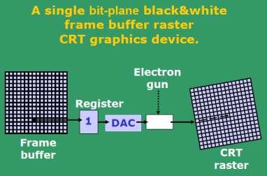
6 o o Heat energy Light energy: it is very short time emitted the light and goes off, while the beam comes back to refresh that point. Phosphorescence is the light given off by the return of the relatively more stable excited electrons to their unexcited state once the electron beam excitation is removed Phosphor s Persistence is defined as the time from the removal of excitation to the moment when phosphorescence has decayed to 10% of the initial light output (decay is exponential). o Long persistence : several seconds o Short persistence : µs (Common in modern displays) REFRESH AND RASTER SCAN DISPLAY SYSTEM Used in television screens Unlike DVST and random-scan which were line-drawing devices, refresh CRT is a Point-Plotting device Raster displays store the display primitives (lines, characters, shaded and patterned areas) in a refresh buffer Refresh Buffer ( frame buffer) stores the drawing primitives in terms of points and pixels components Architecture of a simple raster graphics system Architecture of a Raster System with a fixed portion of the system memory reserved for the frame buffer

 General Line; (b) Special")
7 Entire Screen is a matrix of pixels Each pixel brightness can be controlled Refresh buffer can be visualized as a set of horizontal raster lines or a row of individual pixels Each point is an addressable point in screen and memory Line cannot be drawn directly from one point to another This is causes the effect of Aliasing, Jaggies, or Staircase Effect Refresh/Frame Buffer is also called Bit-Plane Rasterization: (a) General Line; (b) Special Cases
 The raster lines are scanned from top to bottom and then back to")
 Architecture of a raster-graphics system with a display processor Basic video-controller refreshes")
8 Raster is stored as a matrix of pixels representing the entire screen area Entire image is scanned out sequentially by the video controller (one raster line at a time) The raster lines are scanned from top to bottom and then back to the top The intensity of the beam decides the brightness of the pixel At least one memory bit for each pixel (called bit-plane) Architecture of a raster-graphics system with a display processor Basic video-controller refreshes operations


9 Architecture of a raster display Raster scan with outline primitives


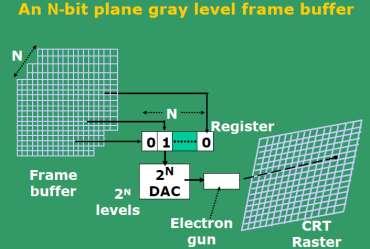
10 Raster scan with filled primitives A typical example: If one uses a 512x512 element raster display, then 2 18 bits are necessary in a single bit plane. Memory size required: 32 KB A DAC (digital-to-analog converter) is used to convert the bit value (0, 1) to analog signals for refreshing the screen Memory size required for N-bit plane gray level frame buffers: N Size in KB Refresh rate to avoid flickering 60 Hz If one uses a 1024x1024 high resolution CRT: N DISPLAY COLOR MEMORY SIZE 1 Black and White 128 KB Color 1 MB Million Color 3 MB Million Color 4 MB

11 Even 32 bits per pixel with 1280x1024 pixels raster are available. Refresh rate of a CRT is the number of times the image is drawn on the screen per second. Reducing refresh rate increases flicker. Horizontal scan rate is the number of scan lines the circuit drives a CRT display per second = refresh rate x number of scan lines Resolution of the screen depends on spot size CRT resolution is not a function of bitmap resolution For larger spot size, resolution decreases Horizontal resolution depends on spot size and beam switching (ON/OFF) speed Bandwidth of the display: The rate at which the beam can be turned OFF to ON and vice-versa. For N pixels per scan line, it is necessary to turn the electron gun at a maximum rate of: N/2 times ON and N/2 times OFF; This will create alternate black and white lines on the screen. Let us now look at some concepts of Video basics and Scan conversion. Raster Scan NTSC (American Standard Video) has 525 horizontal lines with a frame rate of 30 fps. Viewing aspect ratio is 4:3 Each frame has two fields, each containing half the picture. Fields are interlaced or interwoven Fields are presented alternately every other 1/60-th of a sec. One field contains odd scan lines (1,3,5, ) The other contains even scan lines (2,4,6, ) Two types of retrace after every field Interlacing scan lines on a raster scan display; First, all points on the even-numbered (solid) scan lines are displayed; then all points along the odd-numbered (dashed) lines are displayed


12 Schematic of a 7-line interlaced scan line pattern. The odd field begins with line 1. The horizontal retrace is shown dashed. The odd field vertical retrace starts at the bottom center. The even field vertical retrace starts at the bottom right. Horizontal retrace - As the electron beam reaches the right edge of the screen, it is made invisible and rapidly returns to the left edge Time taken for horizontal retrace is typically 17% allotted for a scan line. After odd field scan conversion is complete, the beam is at the bottom center of the screen. After even field scan conversion is complete, the beam is at the bottom right of the screen. Odd field vertical retrace returns the beam (switched OFF) to the top center of the screen Even field vertical retrace returns it to the upper left corner of the screen Two fields are presented alternately for each frame. So we present 60 frames per second. In NTSC, generally 483 lines are visible. This is because, the vertical retrace after each field requires a time equivalent of 21 scan lines So for each field we have time to display: (=525/2) 21 = lines. So with both fields together, we have: 241.5*2 = 483 lines to display. This is the reason for 42 (= ) invisible lines. Let the time available for each scan line be T. Thus, we have: T * 525 * 30 = 1 sec. Thus, T = 63.5 s/scan-line This includes the vertical retrace time. When we consider the horizontal retrace time, the actual time to display all pixels in a scan line (time to scan from left to right only):

13 T = 0.83*T = 53 s. Considering 4:3 aspect ratio, the number of pixels per scan line = 483*4/3 = 644 Thus, time available for the beam to access and display a pixel = 82.3 ns (nano-second). Some examples of pixel access times: Frame Rate Display resolution Pixel Access Time x ns x ns x ns x ns WQUXGA, or Wide Quad Ultra extended Graphics Array Computer Standard Resolution Ratio Ratio (Decimal) Pixels QWXGA 2048 x : M QXGA 2048 x : M WQXGA 2560 x : M QSXGA 2560 x : M WQSXGA 3200 x : M QUXGA 3200 x : M
 N = 1 two colors (B&W) N = 3 8 gray scales or colors N = 8 256")
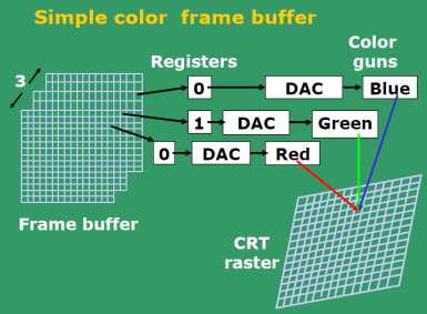
14 WQUXGA 3840 x : M N-bit plane gray level Frame buffer Choice of the number of gray scales and colors depend on the value of N (bit plane size) N = 1 two colors (B&W) N = 3 8 gray scales or colors N = gray scales or colors N = million colors For colored displays (raster-scan), three separate color guns must be used. Each bit/byte plane drives a color gun.
15


16 Operation of a delta-delta, shadow-mask CRT. Three electron guns, aligned with the triangular color-dot patterns on the screen, are directed to each dot triangle by a shadow mask. Color CRT electron gun and shadow mask arrangement
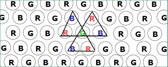
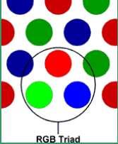
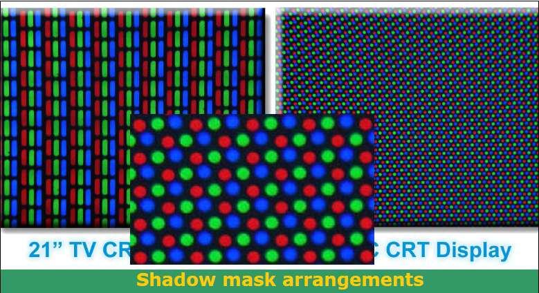
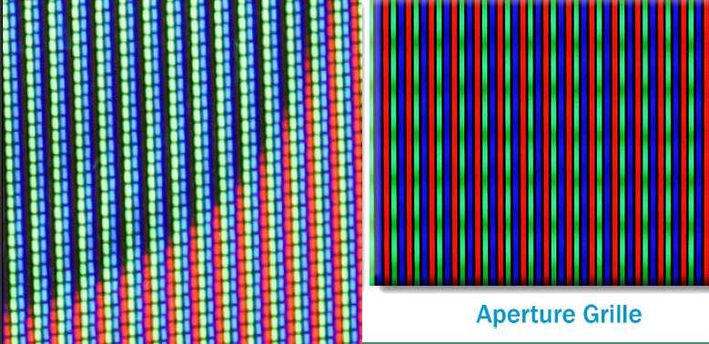
17 Phosphorus dot pattern for a shadow mask CRT


18 Computer Standard Resolution Ratio Dot Pitch (mm) Pixels Pixels per inch QWXGA 2048 x : M QXGA :3 3.1M WQXGA : M QSXGA :4 5.2M WQSXGA :16 6.6M QUXGA :3 7.7M WQUXGA : M The dot pitch of FLC displays (Ferro Liquid Crystal) can be as low as mm Typically 8-bit planes per color is used, which gives a 24-bit plane frame buffer Each group of bit-planes drives an 8-bit DAC Each group generates 256 shades of intensities of red, green or blue
 N-bit plane gray level/color frame buffer with W-bit wide")

19 Hence we obtain 224 = 16,777,216 possible colors. This is called a FULL COLOR FRAME BUFFER Use of LUT (Look-up-table) N-bit plane gray level/color frame buffer with W-bit wide LUT Typically W > N The N-bit register content acts as an index into the lookup table Thus out of 2W possible intensities, that are available, only 2N different intensities are usable at any time The programmer must choose 2N different intensities, based on his requirement, and load the LUT (addressable in memory) before use


20 LCD and FLAT PANEL DISPLAYS LCD is made up of 6 layers vertical polarizer plane; layer of thin grid wires; layer of LCDs; layer of horizontal grid wires; horizontal polarizer; and finally a reflector. LCD material is made up of long crystalline molecules; When the crystals are in an electric field, they all line up in the same direction.
21 Active matrix panels have a transistor at each grid point (X, Y). Crystals are dyed up to provide color. Transistors act as memory, and also cause the crystals to change their state quickly. LCD displays are low cost, low weight, small size and low power consumption The display contains two polarizers, aligned 900 to each other. With the display in its OFF (or twisted) state, light entering the display is plane polarized by the first polarizer. This polarized light passes through the liquid crystal sandwich and then through the second polarizer and is reflected back to the display. Turning the pixel ON (by applying and electric field) causes the crystal to untwist. Light now passing through the liquid crystal sandwich is now absorbed by the second polarizer. The pixel now appears dark. Displays are of two types plasma/gas discharge or Electroluminescent. All flat panel displays are raster refresh displays. A flat CRT is obtained by initially projecting the beam parallel to the screen and then reflecting it through 900. Reflection of the electron beam reduces the depth of the CRT bottle and hence the display. Plasma displays like LCDs are also called active matrix displays. The required voltage or current to control the pixel illumination is supplied using a thinfilm transistor or diode.
Comp 410/510. Computer Graphics Spring Introduction to Graphics Systems
 Comp 410/510 Computer Graphics Spring 2018 Introduction to Graphics Systems Computer Graphics Computer graphics deals with all aspects of 'creating images with a computer - Hardware (PC with graphics card)
Computer Graphics. Raster Scan Display System, Rasterization, Refresh Rate, Video Basics and Scan Conversion
 Computer Graphics Raster Scan Display System, Rasterization, Refresh Rate, Video Basics and Scan Conversion 2 Refresh and Raster Scan Display System Used in Television Screens. Refresh CRT is point plotting
CMPE 466 COMPUTER GRAPHICS
 1 CMPE 466 COMPUTER GRAPHICS Chapter 2 Computer Graphics Hardware Instructor: D. Arifler Material based on - Computer Graphics with OpenGL, Fourth Edition by Donald Hearn, M. Pauline Baker, and Warren
2.2. VIDEO DISPLAY DEVICES
 Introduction to Computer Graphics (CS602) Lecture 02 Graphics Systems 2.1. Introduction of Graphics Systems With the massive development in the field of computer graphics a broad range of graphics hardware
Computer Graphics Prof. Sukhendu Das Dept. of Computer Science and Engineering Indian Institute of Technology, Madras Lecture - 5 CRT Display Devices
 Computer Graphics Prof. Sukhendu Das Dept. of Computer Science and Engineering Indian Institute of Technology, Madras Lecture - 5 CRT Display Devices Hello everybody, welcome back to the lecture on Computer
Computer Graphics: Overview of Graphics Systems
 Computer Graphics: Overview of Graphics Systems By: A. H. Abdul Hafez Abdul.hafez@hku.edu.tr, 1 Outlines 1. Video Display Devices 2. Flat-panel displays 3. Video controller and Raster-Scan System 4. Coordinate
Part 1: Introduction to Computer Graphics
 Part 1: Introduction to Computer Graphics 1. Define computer graphics? The branch of science and technology concerned with methods and techniques for converting data to or from visual presentation using
PTIK UNNES. Lecture 02. Conceptual Model for Computer Graphics and Graphics Hardware Issues
 E3024031 KOMPUTER GRAFIK E3024032 PRAKTIK KOMPUTER GRAFIK PTIK UNNES Lecture 02 Conceptual Model for Computer Graphics and Graphics Hardware Issues 2014 Learning Objectives After carefully listening this
Computer Graphics : Unit - I
 Computer Graphics Unit 1 Introduction: Computer Graphics it is a set of tools to create, manipulate and interact with pictures. Data is visualized through geometric shapes, colors and textures. Video Display
1. Introduction. 1.1 Graphics Areas. Modeling: building specification of shape and appearance properties that can be stored in computer
 1. Introduction 1.1 Graphics Areas Modeling: building specification of shape and appearance properties that can be stored in computer Rendering: creation of shaded images from 3D computer models 2 Animation:
3. Displays and framebuffers
 3. Displays and framebuffers 1 Reading Required Angel, pp.19-31. Hearn & Baker, pp. 36-38, 154-157. Optional Foley et al., sections 1.5, 4.2-4.5 I.E. Sutherland. Sketchpad: a man-machine graphics communication
Displays. History. Cathode ray tubes (CRTs) Modern graphics systems. CSE 457, Autumn 2003 Graphics. » Whirlwind Computer - MIT, 1950
 Modern graphics systems. CSE 457, Autumn 2003 Graphics. » Whirlwind Computer - MIT, 1950") History Displays CSE 457, Autumn 2003 Graphics http://www.cs.washington.edu/education/courses/457/03au/» Whirlwind Computer - MIT, 1950 CRT display» SAGE air-defense system - middle 1950 s Whirlwind II
History Displays CSE 457, Autumn 2003 Graphics http://www.cs.washington.edu/education/courses/457/03au/» Whirlwind Computer - MIT, 1950 CRT display» SAGE air-defense system - middle 1950 s Whirlwind II
Part 1: Introduction to computer graphics 1. Describe Each of the following: a. Computer Graphics. b. Computer Graphics API. c. CG s can be used in
 Part 1: Introduction to computer graphics 1. Describe Each of the following: a. Computer Graphics. b. Computer Graphics API. c. CG s can be used in solving Problems. d. Graphics Pipeline. e. Video Memory.
Reading. 1. Displays and framebuffers. History. Modern graphics systems. Required
 Reading Required 1. Displays and s Angel, pp.19-31. Hearn & Baker, pp. 36-38, 154-157. OpenGL Programming Guide (available online): First four sections of chapter 2 First section of chapter 6 Optional
Reading. Display Devices. Light Gathering. The human retina
 Reading Hear & Baker, Computer graphics (2 nd edition), Chapter 2: Video Display Devices, p. 36-48, Prentice Hall Display Devices Optional.E. Sutherland. Sketchpad: a man-machine graphics communication
Computer Graphics. Introduction
 Computer Graphics Introduction Introduction Computer Graphics : It involves display manipulation and storage of pictures and experimental data for proper visualization using a computer. Typically graphics
MODULE I MCA COMPUTER GRAPHICS ADMN APPLICATIONS OF COMPUTER GRAPHICS
 MODULE 1 1. APPLICATIONS OF COMPUTER GRAPHICS Computer graphics is used in a lot of areas such as science, engineering, medicine, business, industry, government, art, entertainment, advertising, education
Display Technologies CMSC 435. Slides based on Dr. Luebke s slides
 Display Technologies CMSC 435 Slides based on Dr. Luebke s slides Recap: Transforms Basic 2D Transforms: Scaling, Shearing, Rotation, Reflection, Composition of 2D Transforms Basic 3D Transforms: Rotation,
Reading. Displays and framebuffers. Modern graphics systems. History. Required. Angel, section 1.2, chapter 2 through 2.5. Related
 Reading Required Angel, section 1.2, chapter 2 through 2.5 Related Displays and framebuffers Hearn & Baker, Chapter 2, Overview of Graphics Systems OpenGL Programming Guide (the red book ): First four
Introduction to Computer Graphics
 Introduction to Computer Graphics R. J. Renka Department of Computer Science & Engineering University of North Texas 01/16/2010 Introduction Computer Graphics is a subfield of computer science concerned
These are used for producing a narrow and sharply focus beam of electrons.
 CATHOD RAY TUBE (CRT) A CRT is an electronic tube designed to display electrical data. The basic CRT consists of four major components. 1. Electron Gun 2. Focussing & Accelerating Anodes 3. Horizontal
B. TECH. VI SEM. I MID TERM EXAMINATION 2018
 B. TECH. VI SEM. I MID TERM EXAMINATION 2018 BRANCH : COMPUTER SCIENCE ENGINEERING ( CSE ) SUBJECT : 6CS4A COMPUTER GRAPHICS & MULTIMEDIA TECHNIQUES Q 1. Write down mid point ellipse drawing algorithm.
CS2401-COMPUTER GRAPHICS QUESTION BANK
 SRI VENKATESWARA COLLEGE OF ENGINEERING AND TECHNOLOGY THIRUPACHUR. CS2401-COMPUTER GRAPHICS QUESTION BANK UNIT-1-2D PRIMITIVES PART-A 1. Define Persistence Persistence is defined as the time it takes
Monitor and Display Adapters UNIT 4
 Monitor and Display Adapters UNIT 4 TOPIC TO BE COVERED: 4.1: video Basics(CRT Parameters) 4.2: VGA monitors 4.3: Digital Display Technology- Thin Film Displays, Liquid Crystal Displays, Plasma Displays
Display Systems. Viewing Images Rochester Institute of Technology
 Display Systems Viewing Images 1999 Rochester Institute of Technology In This Section... We will explore how display systems work. Cathode Ray Tube Television Computer Monitor Flat Panel Display Liquid
2.4.1 Graphics. Graphics Principles: Example Screen Format IMAGE REPRESNTATION
 2.4.1 Graphics software programs available for the creation of computer graphics. (word art, Objects, shapes, colors, 2D, 3d) IMAGE REPRESNTATION A computer s display screen can be considered as being
Downloads from: https://ravishbegusarai.wordpress.com/download_books/
 1. The graphics can be a. Drawing b. Photograph, movies c. Simulation 11. Vector graphics is composed of a. Pixels b. Paths c. Palette 2. Computer graphics was first used by a. William fetter in 1960 b.
Computer Graphics Hardware
 Computer Graphics Hardware Kenneth H. Carpenter Department of Electrical and Computer Engineering Kansas State University January 26, 2001 - February 5, 2004 1 The CRT display The most commonly used type
Display Devices & its Interfacing
 Display Devices & its Interfacing 3 Display systems are available in various technologies such as i) Cathode ray tubes (CRTs), ii) Liquid crystal displays (LCDs), iii) Plasma displays, and iv) Light emitting
Objectives: Topics covered: Basic terminology Important Definitions Display Processor Raster and Vector Graphics Coordinate Systems Graphics Standards
 MODULE - 1 e-pg Pathshala Subject: Computer Science Paper: Computer Graphics and Visualization Module: Introduction to Computer Graphics Module No: CS/CGV/1 Quadrant 1 e-text Objectives: To get introduced
Lecture Flat Panel Display Devices
 Lecture 13 6.111 Flat Panel Display Devices Outline Overview Flat Panel Display Devices How do Displays Work? Emissive Displays Light Valve Displays Display Drivers Addressing Schemes Display Timing Generator
Overview of Graphics Systems
 CHAPTER - 2 Overview of Graphics Systems Video Display Devices Instructions are stored in a display memory display file display list Modes: immediate each element is processed and displayed retained objects
UNIT 1 INTRODUCTION TO COMPUTER
 UNIT 1 INTRODUCTION TO COMPUTER Introduction to Computer Structure 1.1 Introduction Objectives 1.2 Display Devices 1.2.1 Cathode Ray Tube Technology (CRT) 1.2.2 Random Scan Display 1.2.3 Raster Scan Display
CS 4451A: Computer Graphics. Why Computer Graphics?
 CS 445A: Computer Graphics z CCB, TT 9:3- Why Computer Graphics? z Fun! z Lots of uses: y Art, entertainment y Visualizing complex data/ideas y Concise representation of actions/commands/state y Design/task
Chapter 3. Display Devices and Interfacing
 Chapter 3 Display Devices and Interfacing Monitor Details Collection of dots Matrix of dots creates character Monochrome monitor screen is collection of 350 *720 350 rows and each rows having 720 dots
decodes it along with the normal intensity signal, to determine how to modulate the three colour beams.
 Television Television as we know it today has hardly changed much since the 1950 s. Of course there have been improvements in stereo sound and closed captioning and better receivers for example but compared
CATHODE RAY OSCILLOSCOPE. Basic block diagrams Principle of operation Measurement of voltage, current and frequency
 CATHODE RAY OSCILLOSCOPE Basic block diagrams Principle of operation Measurement of voltage, current and frequency 103 INTRODUCTION: The cathode-ray oscilloscope (CRO) is a multipurpose display instrument
High-resolution screens have become a mainstay on modern smartphones. Initial. Displays 3.1 LCD
 3 Displays Figure 3.1. The University of Texas at Austin s Stallion Tiled Display, made up of 75 Dell 3007WPF LCDs with a total resolution of 307 megapixels (38400 8000 pixels) High-resolution screens
L14 - Video. L14: Spring 2005 Introductory Digital Systems Laboratory
 L14 - Video Slides 2-10 courtesy of Tayo Akinwande Take the graduate course, 6.973 consult Prof. Akinwande Some modifications of these slides by D. E. Troxel 1 How Do Displays Work? Electronic display
Elements of a Television System
 1 Elements of a Television System 1 Elements of a Television System The fundamental aim of a television system is to extend the sense of sight beyond its natural limits, along with the sound associated
CATHODE-RAY OSCILLOSCOPE (CRO)
") CATHODE-RAY OSCILLOSCOPE (CRO) I N T R O D U C T I O N : The cathode-ray oscilloscope (CRO) is a multipurpose display instrument used for the observation, measurement, and analysis of waveforms by plotting
CATHODE-RAY OSCILLOSCOPE (CRO) I N T R O D U C T I O N : The cathode-ray oscilloscope (CRO) is a multipurpose display instrument used for the observation, measurement, and analysis of waveforms by plotting
Screens; media that use additive primaries
 Image display Display is the final stage in the image processing pipeline: Continuous scenes are acquired and digitally processed. The display process essentially converts the discrete image back to continuous
VGA Port. Chapter 5. Pin 5 Pin 10. Pin 1. Pin 6. Pin 11. Pin 15. DB15 VGA Connector (front view) DB15 Connector. Red (R12) Green (T12) Blue (R11)
 DB15 Connector. Red (R12) Green (T12) Blue (R11)") Chapter 5 VGA Port The Spartan-3 Starter Kit board includes a VGA display port and DB15 connector, indicated as 5 in Figure 1-2. Connect this port directly to most PC monitors or flat-panel LCD displays
Chapter 5 VGA Port The Spartan-3 Starter Kit board includes a VGA display port and DB15 connector, indicated as 5 in Figure 1-2. Connect this port directly to most PC monitors or flat-panel LCD displays
CHAPTER 3 OSCILLOSCOPES AND SIGNAL GENERATOR
 CHAPTER 3 OSCILLOSCOPES AND SIGNAL GENERATOR OSCILLOSCOPE 3.1 Introduction The cathode ray oscilloscope (CRO) provides a visual presentation of any waveform applied to the input terminal. The oscilloscope
Sep 09, APPLICATION NOTE 1193 Electronic Displays Comparison
 Sep 09, 2002 APPLICATION NOTE 1193 Electronic s Comparison Abstract: This note compares advantages and disadvantages of Cathode Ray Tubes, Electro-Luminescent, Flip- Dot, Incandescent Light Bulbs, Liquid
1 Your computer screen
 U.S.T.H.B / C.E.I.L Unit 7 Computer science L2 (S2) 1 Your computer screen Discuss the following questions. 1 What type of display do you have? 2 What size is the screen? 3 Can you watch TV on your PC
CHAPTER 4 OSCILLOSCOPES
 CHAPTER 4 OSCILLOSCOPES 4.1 Introduction The cathode ray oscilloscope generally referred to as the oscilloscope, is probably the most versatile electrical measuring instrument available. Some of electrical
The Cathode Ray Tube
 Lesson 2 The Cathode Ray Tube The Cathode Ray Oscilloscope Cathode Ray Oscilloscope Controls Uses of C.R.O. Electric Flux Electric Flux Through a Sphere Gauss s Law The Cathode Ray Tube Example 7 on an
Electrical & Electronic Measurements: Class Notes (15EE36) Module-5. Display Devices
 Module-5. Display Devices") Module-5 Display Devices Syllabus: Introduction Character formats Segment displays Dot matrix displays Bar graph displays Cathode ray tubes Light emitting diodes Liquid crystal displays Nixies Incandescent
Module-5 Display Devices Syllabus: Introduction Character formats Segment displays Dot matrix displays Bar graph displays Cathode ray tubes Light emitting diodes Liquid crystal displays Nixies Incandescent
DISPLAY TECHNOLOGIES. Group 6: Steve Lenhart, Ryan King, Ramsey Akl, and Andrew Scheib
 DISPLAY TECHNOLOGIES Group 6: Steve Lenhart, Ryan King, Ramsey Akl, and Andrew Scheib DISPLAY TECHNOLOGIES Group 6: Steve Lenhart, Ryan King, Ramsey Akl, and Andrew Scheib Introduction First computers
Understanding Multimedia - Basics
 Understanding Multimedia - Basics Joemon Jose Web page: http://www.dcs.gla.ac.uk/~jj/teaching/demms4 Wednesday, 9 th January 2008 Design and Evaluation of Multimedia Systems Lectures video as a medium
VARIOUS DISPLAY TECHNOLOGIESS
 VARIOUS DISPLAY TECHNOLOGIESS Mr. Virat C. Gandhi 1 1 Computer Department, C. U. Shah Technical Institute of Diploma Studies Abstract A lot has been invented from the past till now in regards with the
General Items: Reading Materials: Miscellaneous: Lecture 8 / Chapter 6 COSC1300/ITSC 1401/BCIS /19/2004. Tests? Questions? Anything?
 General Items: Tests? Questions? Anything? Reading Materials: Miscellaneous: F.Farahmand 1 / 14 File: lec7chap6f04.doc What is output? - A computer processes the data and generates output! - Also known
Lecture Flat Panel Display Devices
 Lecture 1 6.976 Flat Panel Display Devices Outline Overview of 6.976 Overview Flat Panel Display Devices Course website http://hackman.mit.edu Reading Assignment: Article by Alt and Noda, IBM Journal of
Chapter 3 Fundamental Concepts in Video. 3.1 Types of Video Signals 3.2 Analog Video 3.3 Digital Video
 Chapter 3 Fundamental Concepts in Video 3.1 Types of Video Signals 3.2 Analog Video 3.3 Digital Video 1 3.1 TYPES OF VIDEO SIGNALS 2 Types of Video Signals Video standards for managing analog output: A.
Television brian egan isnm 2004
 Introduction Mechanical early developments. Electrical how it works. Digital advantages over analogue. brian egan isnm Mechanical television First televisions were mechanical based on revolving disc, first
Lecture 14: Computer Peripherals
 Lecture 14: Computer Peripherals The last homework and lab for the course will involve using programmable logic to make interesting things happen on a computer monitor should be even more fun than the
Presented by: Amany Mohamed Yara Naguib May Mohamed Sara Mahmoud Maha Ali. Supervised by: Dr.Mohamed Abd El Ghany
 Presented by: Amany Mohamed Yara Naguib May Mohamed Sara Mahmoud Maha Ali Supervised by: Dr.Mohamed Abd El Ghany Analogue Terrestrial TV. No satellite Transmission Digital Satellite TV. Uses satellite
Television History. Date / Place E. Nemer - 1
 Television History Television to see from a distance Earlier Selenium photosensitive cells were used for converting light from pictures into electrical signals Real breakthrough invention of CRT AT&T Bell
An Efficient SOC approach to Design CRT controller on CPLD s
 A Monthly Peer Reviewed Open Access International e-journal An Efficient SOC approach to Design CRT controller on CPLD s Abstract: Sudheer Kumar Marsakatla M.tech Student, Department of ECE, ACE Engineering
28 North Lotts, Dublin 1, Ireland Tel: info [AT] phonevolts.com
![28 North Lotts, Dublin 1, Ireland Tel: info [AT] phonevolts.com](/thumbs/91/104995975.jpg "28 North Lotts, Dublin 1, Ireland Tel: info [AT] phonevolts.com") www.phonevolts.ie 28 North Lotts, Dublin 1, Ireland Tel: 01 8728722 Email: info [AT] phonevolts.com PhoneVolts is owned and operated by GSMsolutions.ie What is an LCD? A liquid crystal display (commonly
www.phonevolts.ie 28 North Lotts, Dublin 1, Ireland Tel: 01 8728722 Email: info [AT] phonevolts.com PhoneVolts is owned and operated by GSMsolutions.ie What is an LCD? A liquid crystal display (commonly
Start with some basics: display devices
 Output Concepts Start with some basics: display devices Just how do we get images onto a screen? Most prevalent device: CRT Cathode Ray Tube AKA TV tube 2 Cathode Ray Tubes Cutting edge 1930 s technology
An Overview of Video Coding Algorithms
 An Overview of Video Coding Algorithms Prof. Ja-Ling Wu Department of Computer Science and Information Engineering National Taiwan University Video coding can be viewed as image compression with a temporal
TV Character Generator
 TV Character Generator TV CHARACTER GENERATOR There are many ways to show the results of a microcontroller process in a visual manner, ranging from very simple and cheap, such as lighting an LED, to much
Module 7. Video and Purchasing Components
 Module 7 Video and Purchasing Components Objectives 1. PC Hardware A.1.11 Evaluate video components and standards B.1.10 Evaluate monitors C.1.9 Evaluate and select appropriate components for a custom
OSCILLOSCOPE AND DIGITAL MULTIMETER
 Exp. No #0 OSCILLOSCOPE AND DIGITAL MULTIMETER Date: OBJECTIVE The purpose of the experiment is to understand the operation of cathode ray oscilloscope (CRO) and to become familiar with its usage. Also
Technology White Paper Plasma Displays. NEC Technologies Visual Systems Division
 Technology White Paper Plasma Displays NEC Technologies Visual Systems Division May 1998 1 What is a Color Plasma Display Panel? The term Plasma refers to a flat panel display technology that utilizes
High Performance Raster Scan Displays
 High Performance Raster Scan Displays Item Type text; Proceedings Authors Fowler, Jon F. Publisher International Foundation for Telemetering Journal International Telemetering Conference Proceedings Rights
Graphics Devices and Visual Perception. Human Vision. What is visual perception? Anatomy of the Eye. Spatial Resolution (Rods) Human Field of View
 Human Field of View") Graphics Devices and Visual Perception Human Vision and Perception CRT Displays Liquid Crystal Displays Video Controllers Display Controllers Input Devices Human Vision Eye + Retinal Receptors in eye provide
Graphics Devices and Visual Perception Human Vision and Perception CRT Displays Liquid Crystal Displays Video Controllers Display Controllers Input Devices Human Vision Eye + Retinal Receptors in eye provide
S op o e p C on o t n rol o s L arni n n i g n g O bj b e j ctiv i e v s
 ET 150 Scope Controls Learning Objectives In this lesson you will: learn the location and function of oscilloscope controls. see block diagrams of analog and digital oscilloscopes. see how different input
Basically we are fooling our brains into seeing still images at a fast enough rate so that we think its a moving image.
 Basically we are fooling our brains into seeing still images at a fast enough rate so that we think its a moving image. The formal definition of a Moving Picture... A sequence of consecutive photographic
CATHODE RAY OSCILLOSCOPE (CRO)
") CATHODE RAY OSCILLOSCOPE (CRO) 4.6 (a) Cathode rays CORE Describe the production and detection of cathode rays Describe their deflection in electric fields State that the particles emitted in thermionic
CATHODE RAY OSCILLOSCOPE (CRO) 4.6 (a) Cathode rays CORE Describe the production and detection of cathode rays Describe their deflection in electric fields State that the particles emitted in thermionic
ANTENNAS, WAVE PROPAGATION &TV ENGG. Lecture : TV working
 ANTENNAS, WAVE PROPAGATION &TV ENGG Lecture : TV working Topics to be covered Television working How Television Works? A Simplified Viewpoint?? From Studio to Viewer Television content is developed in
Design of VGA Controller using VHDL for LCD Display using FPGA
 International OPEN ACCESS Journal Of Modern Engineering Research (IJMER) Design of VGA Controller using VHDL for LCD Display using FPGA Khan Huma Aftab 1, Monauwer Alam 2 1, 2 (Department of ECE, Integral
Displays and framebuffers
 Reading Optional Displays and framebuffers Brian Curless CSE 557 Autumn 2017 OpenGL Programming Guide (the red book available online): First four sections of chapter 2 First section of chapter 6 Foley
Visualization Technologies IGS HT Displays. Stefan Seipel Additional Reading. Visual Displays - Basic Technologies
 Visualization Technologies IGS HT 2003 Stefan Seipel (stefan.seipel@it.uu.se) Displays Additional eading oy S. Kalawsky: The Science of Virtual eality and Virtual Environments Addison-Wesley Publishing
Liquid Crystal Displays
 Liquid Crystal Displays Cosmin Ioniţă - Spring 2006 - A brief history 1888 - Friedrich Reinitzer, an Austrian chemist working in the Institute of Plant Physiology at the University of Prague, discovered
EECS150 - Digital Design Lecture 12 - Video Interfacing. Recap and Outline
 EECS150 - Digital Design Lecture 12 - Video Interfacing Oct. 8, 2013 Prof. Ronald Fearing Electrical Engineering and Computer Sciences University of California, Berkeley (slides courtesy of Prof. John
Computer Graphics NV1 (1DT383) Computer Graphics (1TT180) Cary Laxer, Ph.D. Visiting Lecturer
 Computer Graphics (1TT180) Cary Laxer, Ph.D. Visiting Lecturer") Computer Graphics NV1 (1DT383) Computer Graphics (1TT180) Cary Laxer, Ph.D. Visiting Lecturer Today s class Introductions Graphics system overview Thursday, October 25, 2007 Computer Graphics - Class 1
Computer Graphics NV1 (1DT383) Computer Graphics (1TT180) Cary Laxer, Ph.D. Visiting Lecturer Today s class Introductions Graphics system overview Thursday, October 25, 2007 Computer Graphics - Class 1
To discuss. Types of video signals Analog Video Digital Video. Multimedia Computing (CSIT 410) 2
 2") Video Lecture-5 To discuss Types of video signals Analog Video Digital Video (CSIT 410) 2 Types of Video Signals Video Signals can be classified as 1. Composite Video 2. S-Video 3. Component Video (CSIT
Video Lecture-5 To discuss Types of video signals Analog Video Digital Video (CSIT 410) 2 Types of Video Signals Video Signals can be classified as 1. Composite Video 2. S-Video 3. Component Video (CSIT
Hello and welcome to this training module for the STM32L4 Liquid Crystal Display (LCD) controller. This controller can be used in a wide range of
 controller. This controller can be used in a wide range of") Hello and welcome to this training module for the STM32L4 Liquid Crystal Display (LCD) controller. This controller can be used in a wide range of applications such as home appliances, medical, automotive,
Hello and welcome to this training module for the STM32L4 Liquid Crystal Display (LCD) controller. This controller can be used in a wide range of applications such as home appliances, medical, automotive,
PAST EXAM PAPER & MEMO N3 ABOUT THE QUESTION PAPERS:
 EKURHULENI TECH COLLEGE. No. 3 Mogale Square, Krugersdorp. Website: www. ekurhulenitech.co.za Email: info@ekurhulenitech.co.za TEL: 011 040 7343 CELL: 073 770 3028/060 715 4529 PAST EXAM PAPER & MEMO N3
THE OPERATION OF A CATHODE RAY TUBE
 THE OPERATION OF A CATHODE RAY TUBE OBJECT: To acquaint the student with the operation of a cathode ray tube, and to study the effect of varying potential differences on accelerated electrons. THEORY:
Electrical and Electronic Laboratory Faculty of Engineering Chulalongkorn University. Cathode-Ray Oscilloscope (CRO)
") 2141274 Electrical and Electronic Laboratory Faculty of Engineering Chulalongkorn University Cathode-Ray Oscilloscope (CRO) Objectives You will be able to use an oscilloscope to measure voltage, frequency
2141274 Electrical and Electronic Laboratory Faculty of Engineering Chulalongkorn University Cathode-Ray Oscilloscope (CRO) Objectives You will be able to use an oscilloscope to measure voltage, frequency
Module 1: Digital Video Signal Processing Lecture 3: Characterisation of Video raster, Parameters of Analog TV systems, Signal bandwidth
 The Lecture Contains: Analog Video Raster Interlaced Scan Characterization of a video Raster Analog Color TV systems Signal Bandwidth Digital Video Parameters of a digital video Pixel Aspect Ratio file:///d
Innovations in Toshiba s Screen Technologies Table of Contents
 Innovations in Toshiba s Screen Technologies Table of Contents Innovations in Toshiba s Display Technologies... 1 The LCD: Today s Display of Choice... 1 The Latest in Notebook and Workstation LCD Technologies...
Introduction & Colour
 Introduction & Colour Eric C. McCreath School of Computer Science The Australian National University ACT 0200 Australia ericm@cs.anu.edu.au Overview Computer Graphics Uses Basic Hardware and Software Colour
Revision: August 11, E Main Suite D Pullman, WA (509) Voice and Fax. 8 LEDs. Doc: page 1 of 9
 Voice and Fax. 8 LEDs. Doc: page 1 of 9") Digilent DIO4 Peripheral Board Reference Manual www.digilentinc.com Revision: August 11, 2004 215 E Main Suite D Pullman, WA 99163 (509) 334 6306 Voice and Fax Overview The DIO4 circuit board provides
Digilent DIO4 Peripheral Board Reference Manual www.digilentinc.com Revision: August 11, 2004 215 E Main Suite D Pullman, WA 99163 (509) 334 6306 Voice and Fax Overview The DIO4 circuit board provides
Chapter 2. RECORDING TECHNIQUES AND ANIMATION HARDWARE. 2.1 Real-Time Versus Single-Frame Animation
 Chapter 2. RECORDING TECHNIQUES AND ANIMATION HARDWARE Copyright (c) 1998 Rick Parent All rights reserved 2.1 Real-Time Versus Single-Frame Animation 2.2 Film Technology 2.3 Video Technology 2.4 Animation
A Review- on Different Types of Displays
 , pp.327-332 http://dx.doi.org/10.14257/ijmue.2016.11.8.33 A Review- on Different Types of Displays Shubham Shama 1, Udita Jindal 2, Mehul Goyal 3, Sahil Sharma 4 and Vivek Goyal 5 1-4Department of ECE,
the Most Popular Display Technology?
 Why is LCD the Most Popular Display Technology? History of Liquid Crystal Display (LCD) As early as 1889, scientists discovered that chemicals such as cholesteryl benzoate, when melted into liquid form,
How to Match the Color Brightness of Automotive TFT-LCD Panels
 Relative Luminance How to Match the Color Brightness of Automotive TFT-LCD Panels Introduction The need for gamma correction originated with the invention of CRT TV displays. The CRT uses an electron beam
MET71 COMPUTER AIDED DESIGN
 UNIT I INTRODUCTION TO CAD Computer Aided Design (CAD) is assistance of computer in engineering processes such as creation, optimization, analysis and modifications. CAD involves creating computer models
Multimedia Systems Video I (Basics of Analog and Digital Video) Mahdi Amiri April 2011 Sharif University of Technology
 Mahdi Amiri April 2011 Sharif University of Technology") Course Presentation Multimedia Systems Video I (Basics of Analog and Digital Video) Mahdi Amiri April 2011 Sharif University of Technology Video Visual Effect of Motion The visual effect of motion is due
Course Presentation Multimedia Systems Video I (Basics of Analog and Digital Video) Mahdi Amiri April 2011 Sharif University of Technology Video Visual Effect of Motion The visual effect of motion is due
Mahdi Amiri. April Sharif University of Technology
 Course Presentation Multimedia Systems Video I (Basics of Analog and Digital Video) Mahdi Amiri April 2014 Sharif University of Technology Video Visual Effect of Motion The visual effect of motion is due
Chapter 9 MSI Logic Circuits
 Chapter 9 MSI Logic Circuits Chapter 9 Objectives Selected areas covered in this chapter: Analyzing/using decoders & encoders in circuits. Advantages and disadvantages of LEDs and LCDs. Observation/analysis
Liquid Crystal Display (LCD)
") Liquid Crystal Display (LCD) When coming into contact with grooved surface in a fixed direction, liquid crystal molecules line up parallelly along the grooves. When coming into contact with grooved surface
Liquid Crystal Display (LCD) When coming into contact with grooved surface in a fixed direction, liquid crystal molecules line up parallelly along the grooves. When coming into contact with grooved surface
Data Sheet. Electronic displays
 Data Pack F Issued November 0 029629 Data Sheet Electronic displays Three types of display are available; each has differences as far as the display appearance, operation and electrical characteristics
THE OPERATION OF A CATHODE RAY TUBE
 THE OPERATION OF A CATHODE RAY TUBE OBJECT: To acquaint the student with the operation of a cathode ray tube, and to study the effect of varying potential differences on accelerated electrons. THEORY:
Tutorial Cathode Rays Year 12 Physics - Module 9.3 Motors and Generators
 Tutorial 9.4.1.2 Cathode Rays Year 12 Physics - Module 9.3 Motors and Generators For use with Lesson 9.4.1 Cathode Rays 1. Identify the properties of cathode rays that indicated that they might be particles.