Color Organ Triple Deluxe II.
|
|
|
- Jack Stone
- 6 years ago
- Views:
Transcription
1 Food Living Outside Play Technology Workshop Color Organ Triple Deluxe II by ledartist on January 13, 2013 Table of Contents Color Organ Triple Deluxe II 1 Intro: Color Organ Triple Deluxe II 2 Step 1: The Problems & The Solutions 2 Step 2: Circuit 3 File Downloads 4 Step 3: Assembly 4 Step 4: Use 5 Related Instructables 6 Advertisements 6 Comments 6
2 Author:ledartist Visit TheLEDartcom for more I am an electronic artist living in Brooklyn, NY I work with LEDs and microcontrollers to create beautiful objects Intro: Color Organ Triple Deluxe II Making Refinements to the Old Project I put together the Color Organ Triple Deluxe over a year ago It was a bare minimum version of color organ circuit using LEDs instead of incandescent lamps that traditional color organs use The circuit worked pretty well, considering the simplicity of the circuit However I just kept feeling like this project deserves further refinements So I went back to the drawing board (or breadboard) and took a hard look at the circuit The result? Please take a look at the video Step 1: The Problems & The Solutions The Problems There were a few problems The transistors in the circuit was biased in the way that it was supply voltage dependent, as well as device dependent - in other words, if the voltage was too high or too low, or the transistors had a bit of different characteristics, the circuit did not perform well The filter performance was also a bit poor - the separation between the frequency bands were not so great The Solutions First, I changed the initial gain stage from single transistor design to two transistor design It's a basic class-a common emitter amplifier followed by an emitter follower They are direct coupled for optimum performance, as well as reduced part count (always important for me to design circuits with the least number of parts) Adding the emitter follower stage allowed the low output impedance needed for the filters to perform well The biasing circuit was also revised to be less device and voltage dependent Second, the filters were refined to have better separations Input and output impedance to the filters are better matched to achieve better efficiency as well Third, the LED driver circuits were given another transistor Actually, in the original design, the output buffer and the LED driver was done by the same transistors Now the filter outputs are buffered by emitter followers, then the filtered audio waves are rectified before going into the LED drivers Those changes made a huge difference And I tweaked the component values obsessively to get the best performance Sensitivity adjustment control is also added There are many additional parts compared to the earlier version, but the result is totally worth it The LEDs now respond to music very, very nicely

3 Step 2: Circuit Here are the circuit schematics, BOM, as well as the PCB layout The filter response graph is also shown Keep in mind that the graph is more of a perceptual one than actual The circuit is loosely based on the many vintage circuits before it, with a few improvements The input buffer/gain stage is designed to have low output impedance This is important for the filter stages that follow This stage is also designed to give high gain and maximum output signal level, since the filters are of passive type so will lose some signal (This amplifier stage took me the most time to design I tried out many topologies and parameters I think I found the best balance between simplicity, stability and performance Unlike using op-amp, designing amplifier with transistors is an art of compromise) The use of emitter follower as rectifier is my original idea (Q3, 5 and 7) Combined with the bias point set (by R8 and 9 and so on) right below the point the LED driver turns on makes this color organ very sensitive to the lower volume of audio input, while eliminating the diodes typically used here BOM 3x 47 ohm - R4,17,20 6x 150 ohm - R10,15,16,16b,21,21b 2x 270 ohm - R11,11b 1x 470 ohm - R6 2x 1k ohm - R1,2 2x 47k ohm - R7,12 4x 10k ohm - R3,9,14,19 3x 270k ohm - R8,13,18 1x 12M ohm - R5 1x 10k ohm potentiometer - VR1 1x 47nF (00047uF) - C9 2x 22nF (0022uF) - C6,7 1x 022uF EC - C3 1x 1uF EC - C4 3x 47uF EC - C5,8,10 1x 10 uf EC 16V or higher - C2 1x 47uF EC 16V or higher - C1 8x MPS2222A or Equivalent - Q1-8 6x Red LED - D1-6 6x Green LED - D7-12 6x Blue LED - D x 35mm Stereo Jack - CN1 1x DC Power Jack All resistors are 1/8W (or higher) carbon film type, 5% precision Small capacitors are film type, and 022uF and above are electrolytic type having voltage rating of 16V or higher Parts Substitutions This type of analog circuits tend to be picky about the part values, so it's best not to change out resistor values, etc unless you know what you are doing Resister and capacitor types are not very critical, so just use any type you might have Using ceramic capacitors instead of film for example, is fine I used MPS2222A transistor, which can be substituted by number of general purpose transistors of similar specs The ones I tested are 2N4400, 2N4401, and 2N3904 Q1 is more critical than other transistors in this circuit The biasing is adjusted for transistors having the hfe around 200 If you use different transistor, you might want to check the voltage at Q1 collector - the voltage here should be between 45 to 6V when 12V supply is applied Adjust R5 or try different transistors for Q1 if it's too high or low PCB Layout PCB layout is provided as PDF for home brew PCB makers It's a single layer design, so it should be easy to make your own Kits and PCBs Kits and PCBs of this project are available at my website
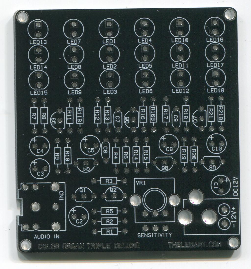
4 File Downloads Color Organ Triple Deluxe schematic-rev3cpdf (83 KB) [NOTE: When saving, if you see tmp as the file ext, rename it to 'Color Organ Triple Deluxe schematic-rev3cpdf'] ColorOrganTripleDeluxePCBpdf (52 KB) [NOTE: When saving, if you see tmp as the file ext, rename it to 'ColorOrganTripleDeluxePCBpdf'] Step 3: Assembly There are 8 transistors, and many resistors, capacitors and LEDs, but the assembly is very straightforward as they are all familier through hole parts (and no ICs) In a way, Color Organ Triple Deluxe II is built like circuits from the 70's If you are like me, you will appreciate the modern vintage feel of all discrete part design I recommend soldering the lower profile parts, first, then move on to taller and taller parts I arranged the BOM in the order of soldering below: Soldering Order Resistors (bend the leads) (reference on color code) 3x 47 ohm (yellow, violet, black, gold) - R4,17,20 6x 150 ohm (brown, green, brown, gold) - R10,15,16,16b,21,21b 2x 270 ohm (red, violet, brown, gold) - R11,11b 1x 470 ohm (yellow, violet, brown, gold) - R6 2x 1k ohm (brown, black, red, gold) - R1,2 2x 47k ohm (yellow, violet, red, gold) - R7,12 4x 10k ohm (brown, black, orange, gold) - R3,9,14,19 3x 270k ohm (red, violet, yellow, gold) - R8,13,18 1x 12M ohm (brown, red, green, gold) - R5 1x 35mm Stereo Jack - CN1 Capacitors (watch the polarity for electrolytic capacitors - long leads go into the holes with "+" sign on the PCB)
 8x MPS2222A or Equivalent - Q1-8 LEDs (polarity")
 Some parts of Color Organ Triple Deluxe II are very sensitive")
5 1x 47nF (00047uF) Film Capacitor - C9 2x 22nF (0022uF) Film Capacitor - C6,7 1x 022uF Electrolytic Capacitor* - C3 1x 1uF Electrolytic Capacitor* - C4 3x 47uF Electrolytic Capacitor* - C5,8,10 1x 10 uf Electrolytic Capacitor* - C2 1x 47uF Electrolytic Capacitor* - C1 Transistors (polarity - make sure to orient them to the shape printed on the PCB) 8x MPS2222A or Equivalent - Q1-8 LEDs (polarity - make sure to orient them to the shape printed on the PCB) 6x Red LED - D1-6 6x Green LED - D7-12 6x Blue LED - D x DC Power Jack 1x 10k (50k) ohm potentiometer - VR1 Notes on Solder Resin/Flux Some solder resin/flux is electrically conductive (resin or flux is inside solder wire to help solder to adhere to the joints) Some parts of Color Organ Triple Deluxe II are very sensitive to even a tiny amount of electrical leakage caused by soldering resin/flux If the LEDs on Color Organ Triple Deluxe II stays lit without any sound signal coming in, you need to clean the PCB to remove the resin/flux "No Clean" type flux cause no problems (as the name implies), but more typical resin type flux can cause good amount of leakage, and cleaning might be required You can use an acid brush or an old toothbrush immersed in rubbing alcohol to scrub the back of the PCB Rince out the brush, wet with alcohol again and scrub another round or to until all the resin residue is gone Make sure to dry the PCB completely before connecting to the power supply Image Notes 1 Resistors 2 Film capacitors 3 Electrolytic capacitor 4 LEDs 5 Transistors 6 DC Power Jack 7 35mm Stereo Jack 8 Potentiometer 9 PCB Step 4: Use Color Organ Triple Deluxe II is designed to run by 12V DC power supply The circuit works pretty ok with 9V power, though However 9V battery is not recommended as a power source because of the relatively high current draw (about 25mA at idol) It's best to connect to a regulated 12V DC power supply Be careful if you want to use a typical wall wart - they can output much higher voltage than they are rated - sometimes as high as 18V from a 12V one Color Organ Triple Deluxe II can operate safely from up to about 15V power (If you want to use non-regulated AC adaptor, try a 9V rated one - they typically produce around 13V) Audio source can be any "line level" output from audio equipment, or headphone output from computer sound cards and ipod/mp3 players If you want to listen to the music while using Color Organ Triple Deluxe II, you might need a splitter cable Connect Color Organ Triple Deluxe II to your audio source of choice, and give it a play I found music with good amount of beats to give best results Adjust the potentiometer (sensitivity level) according to the sound level The LEDs react to the sound volume in a pretty linear manner that it feels like the Color Organ is translating sound into light The light out of the LEDs are blinding bright You can use Color Organ Triple Deluxe II as a wall wash - project the light towards walls or ceiling and dim the lights in the room You will discover a new joy of listing to music
 by Elemental LED LED Color Organ Triple Deluxe by ledartist Worlds smallest color organ by jduffy54 Music Flashing LED Bar by HM- Innovations Advertisements")


6 Related Instructables RGB sound synched LED light (video) by emihackr97 2 Channel DVD LED COLOR ORGAN by wgsinc Recycled Material Musical Tree Lamp with Color Changing LEDs (Photos) by Elemental LED LED Color Organ Triple Deluxe by ledartist Worlds smallest color organ by jduffy54 Music Flashing LED Bar by HM- Innovations Advertisements Comments 6 comments Add Comment lhazwani says: Jan 19, :23 AM REPLY Hi can i know which software and what version do you construct the PCB circuit and the schematic diagram? it seems my ISIS does not have the virtual ground Thank you :) ledartist says: Jan 19, :57 AM REPLY I use Osmond (on Mac OS X) to design PCBs, but this software doesn't have schematic capture I draw my schematics using Adobe Illustrator So it's like drawing manually There's no virtual ground in this color organ circuit though Aki Tomdf says: Jan 15, :43 PM REPLY I've wanted to build one of these for years, ever since I got one of those Velleman single channel kits In a way I'm almost disappointing, I won't bother to figure it out myself now that I have your instructions I also just wanted to say that your kits, videos and documentation are absolutely top-notch, and the fact that you share your work openly is the epitome of class Thank you, I mean it sincerely!
7 ledartist says: Jan 15, :49 PM REPLY Thanks! Yeah this was one of those projects that I wanted to tackle for years as well I just wanted to make it simpler than the typical modern implementation using OP-amps So I gave myself a chalenge to design one without an OP-amp Aki JVC-Force says: Jan 14, :27 PM REPLY Cool, it is not surface mount! The three band separation is very impressive Color organ + LEDs = future retro! ledartist says: Jan 15, :42 AM REPLY Those little transistors can do a lot Analog circuit rocks!
8 Level Frequency Filter Responces 320Hz 800Hz 24kHz AUDIO 1 R1 1k AUDIO 2 GND R2 1k VR1 10k +12V POWER C1 47u Schematic BOM 3x 47 ohm - R4,17,20 6x 150 ohm - R10,15,16,16b,21,21b 2x 270 ohm - R11,11b 1x 470 ohm - R6 2x 1k ohm - R1,2 2x 47k ohm - R7,12 4x 10k ohm - R3,9,14,19 R3 10k C2 10u Q1 R5 12M Q2 R4 47R R6 470R 3x 270k ohm - R8,13,18 1x 12M ohm - R5 1x 10k (50k) ohm pot - VR1 1x 47nF (00047uF) - C9 2x 22nF (0022uF) - C6,7 1x 022uF EC - C3 1x 1uF EC - C4 R7 47k C3 022u R12 47k C6 22n R17 47R D1 C4 1u R9 10k R8 270k R10 C5 1u Q3 R11 270R Q4 D2 D3 D7 C7 22n R14 10k R13 270k R15 C8 1u Q5 R16 Q6 D8 D9 D13 C9 47n R19 10k R18 270k R20 47R C10 1u Q7 R21 Q8 D14 D15 3x 47uF EC - C5,8,10 1x 10 uf EC 16V or higher - C2 1x 47uF EC 16V or higher - C1 8x MPS2222A or Equivalent - Q1-8 6x Red LED - D1-6 6x Green LED - D7-12 6x Blue LED - D13-18 D4 D5 D6 R11b 270R D10 D11 D12 R16b D16 D17 D18 R21b Title Date Low Mid High Color Organ Triple Deluxe 2 Rev 12/29/2012 3c Sheet 1 of 1 Designed by Akimitsu Sadoi
9
10
11
Mal-2 assembly guide v1.0
 Mal-2 assembly guide v.0 SONIC POTIONS Schematic and BOM The BOM can be found on Google Docs Prepare the PCB Separate the PCBs using some pliers. PCB We start with the lower PCB and assemble it beginning
Total solder points: 123 Difficulty level: beginner 1. advanced AUDIO ANALYZER K8098. audio gea Give your. . high-tech ILLUSTRATED ASSEMBLY MANUAL
 Total solder points: 123 Difficulty level: beginner 1 2 3 4 5 advanced AUDIO ANALYZER K8098 ra audio gea Give your. look high-tech ILLUSTRATED ASSEMBLY MANUAL H8098IP-1 Features & Specifications Features
Nixie Clock Type Frank 2 Z570M
 Assembly Instructions And User Guide Nixie Clock Type Frank 2 Z570M Software version: 7R PCB Revision: 11 April 09-1 - 1. INTRODUCTION 1.1 About the clock Nixie clock type Frank 2 is a compact design with
Introduction 1. Green status LED, controlled by output signal ST. Sounder, controlled by output signal Q6. Push switch on input D6
 Introduction 1 Welcome to the GENIE microcontroller system! The activity kit allows you to experiment with a wide variety of inputs and outputs... so why not try reading sensors, controlling lights or
Tube Cricket Build Guide
 Tube Cricket Build Guide The Tube Cricket is a small-wattage amp that puts out about 1 watt of audio power. With a 12AU7 tube-preamp and a JRC386 power amp, the Tube Cricket gives you great tone in a compact
Nixie Clock Type Frank 3
 Assembly Instructions And User Guide Nixie Clock Type Frank 3 Software version: 7R PCB Version: 11 April 09-1 - 1. INTRODUCTION 1.1 About the clock Nixie clock type Frank 3 is a compact design with all
Nixie Tube Clock Type Marsden
 Assembly Instructions And User Guide Nixie Tube Clock Type Marsden Software version: RTC-1.3 PCB Revision: 16 Aug 10-1 - 1. INTRODUCTION 1.1 About the clock Nixie clock type Marsden is a compact design
Introduction 1. Digital inputs D6 and D7. Battery connects here (red wire to +V, black wire to 0V )
") Introduction 1 Welcome to the magical world of GENIE! The project board is ideal when you want to add intelligence to other design or electronics projects. Simply wire up your inputs and outputs and away
Introduction 1 Welcome to the magical world of GENIE! The project board is ideal when you want to add intelligence to other design or electronics projects. Simply wire up your inputs and outputs and away
Bill of Materials: Super Simple Water Level Control PART NO
 Super Simple Water Level Control PART NO. 2169109 Design a simple water controller in which electrodes are required to sense high and low water levels in a tank. Whenever the water level falls below the
Multi-Key v2.4 Multi-Function Amplifier Keying Interface
 Multi-Key v2.4 Multi-Function Amplifier Keying Interface ASSEMBLY & OPERATION INSTRUCTIONS INTRODUCTION The Harbach Electronics, LLC Multi-Key is a multi-function external device designed for the safe
MONO AMPLIFIER KIT ESSENTIAL INFORMATION. Version 2.2 CREATE YOUR OWN SPEAKER DOCK WITH THIS
 ESSENTIAL INFORMATION BUILD INSTRUCTIONS CHECKING YOUR PCB & FAULT-FINDING MECHANICAL DETAILS HOW THE KIT WORKS CREATE YOUR OWN SPEAKER DOCK WITH THIS MONO AMPLIFIER KIT Version 2.2 Build Instructions
Introduction 1. Green status LED, controlled by output signal ST
 Introduction 1 Welcome to the magical world of GENIE! The project board is ideal when you want to add intelligence to other design or electronics projects. Simply wire up your inputs and outputs and away
VU-1 VU Meter Kit Volume Unit Meter
 VU-1 VU Meter Kit Volume Unit Meter Simplicity Counts, Detail Matters. No part of this document may be reproduced, either mechanically or electronically, posted online on the Internet, in whole or in part,
Nixie Clock Type Quattro'
 Assembly Instructions And User Guide Nixie Clock Type Quattro' - 1 - Issue Number Date REVISION HISTORY 2 8 Sept 2012 Errors corrected 1 27 July 2012 New document Reason for Issue - 2 - 1.1 Nixie Quattro
RECORD & PLAYBACK KIT
 TEACHING RESOURCES SCHEMES OF WORK DEVELOPING A SPECIFICATION COMPONENT FACTSHEETS HOW TO SOLDER GUIDE ADD AN AUDIO MESSAGE TO YOUR PRODUCT WITH THIS RECORD & PLAYBACK KIT Version 2.1 Index of Sheets TEACHING
MAKE AN RGB CONTROL KNOB.
 MAKE AN RGB CONTROL KNOB. This is a knob based colour changing controller that uses a custom programmed microcontroller to pack a lot of features into a small affordable kit. The module can drive up to
Build A Video Switcher
 Build A Video Switcher VIDEOSISTEMAS serviciotecnico@videosistemas.com www.videosistemas.com Reprinted with permission from Electronics Now Magazine September 1997 issue Copyright Gernsback Publications,
N3ZI Digital Dial Manual For kit with Backlit LCD Rev 4.00 Jan 2013 PCB
 N3ZI Digital Dial Manual For kit with Backlit LCD Rev 4.00 Jan 2013 PCB Kit Components Item Qty Designator Part Color/Marking PCB 1 LCD Display 1 LCD 1602 Volt Regulator 1 U1 78L05, Black TO-92 Prescaler
H2633IP-1 RELAY CARD K2633
 H2633IP-1 RELAY CARD K2633 Control up to 4 high-power circuits from a low-power drive circuit. Features & Specifications The connection of a few relays to the outputs of an electronic circuit might be
Main PCB (The small one)
") Thanks for choosing our kits! This manual is written taking with the problems that we usually find in our workshops in mind. Also the order is meant to make assembly as easy as possible. Some steps are
Thanks for choosing our kits! This manual is written taking with the problems that we usually find in our workshops in mind. Also the order is meant to make assembly as easy as possible. Some steps are
Assembly Instructions And User Guide. Nixie FunKlock. FunKlock Issue 4 (1 February 2017)
") Assembly Instructions And User Guide Nixie FunKlock - 1 - Issue Number Date REVISION HISTORY 4 1 February 2017 New diode for D2 3 27 December 2013 C7 / C8 error page 15 2 7 November 2013 Errors corrected
Assembly Instructions And User Guide Nixie FunKlock - 1 - Issue Number Date REVISION HISTORY 4 1 February 2017 New diode for D2 3 27 December 2013 C7 / C8 error page 15 2 7 November 2013 Errors corrected
Total solder points: 117 Difficulty level: beginner advanced. RGB Controller K8088 ILLUSTRATED ASSEMBLY MANUAL
 Total solder points: 117 Difficulty level: beginner 1 2 3 4 5 advanced RGB Controller K8088 Control incandescent bulbs, LEDs, common anode led strips, etc... ILLUSTRATED ASSEMBLY MANUAL H8088IP-1 Features
N3ZI Digital Dial Manual For kit with Serial LCD Rev 3.04 Aug 2012
 N3ZI Digital Dial Manual For kit with Serial LCD Rev 3.04 Aug 2012 Kit properly assembled and configured for Standard Serial LCD (LCD Not yet connected) Kit Components Item Qty Designator Part Color/Marking
QUIZ BUZZER KIT TEACHING RESOURCES. Version 2.0 WHO ANSWERED FIRST? FIND OUT WITH THIS
 TEACHING RESOURCES SCHEMES OF WORK DEVELOPING A SPECIFICATION COMPONENT FACTSHEETS HOW TO SOLDER GUIDE WHO ANSWERED FIRST? FIND OUT WITH THIS QUIZ BUZZER KIT Version 2.0 Index of Sheets TEACHING RESOURCES
16 Stage Bi-Directional LED Sequencer
 16 Stage Bi-Directional LED Sequencer The bi-directional sequencer uses a 4 bit binary up/down counter (CD4516) and two "1 of 8 line decoders" (74HC138 or 74HCT138) to generate the popular "Night Rider"
Documentation VFD clock 8 a clock
 Documentation VFD clock 8 a clock This documentation is protected by our copyright. It must not be used for commercial purposes. Congratulations on your purchase of your VFD clock. To guarantee success
While the parts are already inventoried at the factory, please verify the inventory check as you go:
 Thank you for purchasing the kit for building the WJ9J DTMF controller. After building, you should read the document on operation (WJ9JDTMFControllerV5.pdf) in order to use. This is also in the link in
DIY KIT MHZ 8-DIGIT FREQUENCY METER
 This kit is a stand-alone frequency meter capable of measuring repetitive signals up to a frequency of 50MHz. It has two frequency ranges (15 and 50 MHz) as well as two sampling rates (0.1 and 1 second).
COLOUR CHANGING USB LAMP KIT
 TEACHING RESOURCES SCHEMES OF WORK DEVELOPING A SPECIFICATION COMPONENT FACTSHEETS HOW TO SOLDER GUIDE SEE AMAZING LIGHTING EFFECTS WITH THIS COLOUR CHANGING USB LAMP KIT Version 2.1 Index of Sheets TEACHING
ELECTRONIC GAME KIT TEACHING RESOURCES. Version 2.0 BUILD YOUR OWN MEMORY & REACTIONS
 TEACHING RESOURCES SCHEMES OF WORK DEVELOPING A SPECIFICATION COMPONENT FACTSHEETS HOW TO SOLDER GUIDE BUILD YOUR OWN MEMORY & REACTIONS ELECTRONIC GAME KIT Version 2.0 Index of Sheets TEACHING RESOURCES
Nutube.US. 6P1 Evaluation Board. User Manual
 Nutube.US 6P1 Evaluation Board User Manual Introduction The 6P1 Evaluation Board (EVB) is a vehicle for testing and evaluating the Korg Nutube 6P1 dual triode in audio circuits. This product is designed
ADD AN AUDIO MESSAGE TO YOUR PRODUCT WITH THIS RECORD & PLAYBACK KIT
 ADD AN AUDIO MESSAGE TO YOUR PRODUCT WITH THIS RECORD & PLAYBACK KIT BUILD INSTRUCTIONS Before you start take a look at the Printed Circuit Board (PCB). The components go in the side with the writing on
MAIN PCB (The small one) OPEN MAIN BOARD BAG A
 OPEN MAIN BOARD BAG A") THANKS FOR CHOOSING ONE OF OUR KITS! This manual has been written taking into account the common issues that we often find people experience in our workshops. The order in which the components are placed
THANKS FOR CHOOSING ONE OF OUR KITS! This manual has been written taking into account the common issues that we often find people experience in our workshops. The order in which the components are placed
Australian Technical Production Services
 Australian Technical Production Services Dual Rail Crowbar Copyright notice. These notes, the design, schematics and diagrams are Copyright Richard Freeman, 2015 While I am happy for the notes to be printed
Nixie Clock Kit IN-12B color LED backlit Operation Manual Nixie Clock Kit IN-12B V6.0 ( All Right Reserved 2015 )
") Nixie Clock Kit IN-B color LED backlit Operation Manual Nixie Clock Kit IN-B V. ( All Right Reserved ) - - Operation Manual IN-B Nixie Clock Power for your Nixie Clock The clock does not include a wall
Nixie Clock Kit IN-B color LED backlit Operation Manual Nixie Clock Kit IN-B V. ( All Right Reserved ) - - Operation Manual IN-B Nixie Clock Power for your Nixie Clock The clock does not include a wall
This Unit may form part of a National Qualification Group Award or may be offered on a free standing basis.
 National Unit Specification: general information CODE F5JJ 11 SUMMARY The Unit is intended for candidates with little or no prior knowledge of Analogue or Digital Electronic Circuits. It provides an opportunity
TKEY-K16. Touch CW automatic electronic keyer. (No moving parts no contacts) Assembly manual. Last review: March 15, 2018
 Assembly manual. Last review: March 15, 2018") TKEY-K16 Touch CW automatic electronic keyer (No moving parts no contacts) Assembly manual Last review: March 15, 2018 Commands and use manual of the K16 and Updates and news: www.ea3gcy.com Thanks for
TKEY-K16 Touch CW automatic electronic keyer (No moving parts no contacts) Assembly manual Last review: March 15, 2018 Commands and use manual of the K16 and Updates and news: www.ea3gcy.com Thanks for
SN-Class Nixie Clock Kits
 Assembly Instructions And User Guide SN-Class Nixie Clock Kits - 1 - REVISION HISTORY Issue Date Reason for Issue Number 1 20 November 2017 New document - 2 - 1. INTRODUCTION 1.1 About the How can the
VU Meter Buffer DIY Kit
 VU Meter Buffer DIY Kit Warning This document is distributed for educational purposes only. This equipment operates at potentially lethal voltages. Only trained, qualified personnel should operate, maintain,
Installing The PK-AM keyer and. from Jackson Harbor Press Operating: A Morse code keyer chip with pot speed control
 Installing The PK-AM keyer and from Jackson Harbor Press Operating: A Morse code keyer chip with pot speed control The PK-AM keyer is a modification for the PK-AM kit, it changes the AM transmitter to
Nixie Clock Kit V1.08 Assembly and Operation
 Nixie Clock Kit V1.08 Assembly and Operation Hardware Revision 14.05.2005 Software Version 6.0 Revision 19.04.2006 This document is copyrighted. No parts of this documentation may be used commercially.
Build Your Own Clone Super 8 Kit Instructions
 Build Your Own Clone Super 8 Kit Instructions Warranty: BYOC, Inc. guarantees that your kit will be complete and that all parts and components will arrive as described, functioning and free of defect.
Lab 7: Soldering - Traffic Light Controller ReadMeFirst
 Lab 7: Soldering - Traffic Light Controller ReadMeFirst Lab Summary The two-way traffic light controller provides you with a quick project to learn basic soldering skills. Grading for the project has been
STROBOSCOPE LIGHT EFFECT KIT
 STROBOSCOPE LIGHT EFFECT KIT Easy to build stroboscope for general applications Flash frequency: 5 to 15 flashes per second Power supply: 110VAC Power consumption: 13W max. PCB dimensions: 50 x 75mm modifications
ASM-2 Manual Appendix A
 ASM-2 Manual Appendix A Assembly Guidelines June 30 th, 2005 Please note that this document is still currently under revision and we apologise for any errors or omissions. Readers should feel free to e-mail
GUIDE TO ASSEMBLY OF ERICA SYNTHS DELAY MODULE
 If you are reading this, most probably, you are about to build Erica Synths DIY DELAY module. The module is 4mm deep, skiff friendly, has solid mechanical construction and doesn t require wiring. Erica
LP-PAN Preamp Kit Assembly Manual
 LP-PAN Preamp Kit Assembly Manual December 2010 TelePost Incorporated Rev. A9 1 Table of Contents Introduction... 2 Specifications... 3 Parts List... 4 Assembly... 5 Checkout / Schematic... 9 Introduction
DDS VFO CONSTRUCTION MANUAL. DDS VFO Construction Manual Issue 1.1 Page 1
 DDS VFO CONSTRUCTION MANUAL DDS VFO Construction Manual Issue 1.1 Page 1 Important Please read before starting assembly STATIC PRECAUTION The DDS VFO kit contains the following components which can be
Lab 7: Soldering - Traffic Light Controller ReadMeFirst
 Lab 7: Soldering - Traffic Light Controller ReadMeFirst Lab Summary The two way traffic light controller provides you with a quick project to learn basic soldering skills. Grading for the project has been
TECHNOLOGY WILL SAVE US: THE LUMIPHONE
 TECHNOLOGY WILL SAVE US: THE LUMIPHONE This is a step-by-step guide to soldering your own Lumiphone. The equipment you should have at your station: goggles, soldering mat, soldering Iron, solder and side
The NorCal SMT Dummy Load Assembly and Operating Manual Rev. 1.0 January 4, 2005
 The NorCal SMT Dummy Load Assembly and Operating Manual Rev. 1.0 January 4, 2005 Copyright 2005 W3CD 1 1. Introduction The NorCal SMT Dummy Load is a practice kit for anyone wishing to gain some experience
DIY Guide - Building Franky v1.1, the SEGA Audio and Videocard for MSX
 DIY Guide - Building Franky v1.1, the SEGA Audio and Videocard for MSX 2015 FRS & MSXpró. Translation by FRS and Supersoniqs. Table of Contents Introduction... 3 Materials needed... 3 Audio volume boost...
XTAL Bank DDS Version 0.02 Sept Preliminary, highly likely to contain numerous errors
 XTAL Bank DDS Version 002 Sept 7 2012 Preliminary, highly likely to contain numerous errors The photo above shows the fully assembled Xtal Bank DDS with 2 DDS modules installed (The kit is normally only
Galilean Moons. dual amplitude transmutator. DIY ASSEMBLY MANUAL v1.02
 Galilean Moons dual amplitude transmutator DIY ASSEMBLY MANUAL v1.02 Contents Contents... 2 Introduction... 3 Eurorack Kit Assembly... 4 Resistors... 4 IC Sockets... 5 Ceramic/Film Capacitors... 5 Transistors
Christmas LED Snowflake Project
 Christmas LED Snowflake Project Version 1.1 (01/12/2008) The snowflake is a follow-on from my Christmas star project from a few years ago. This year I decided to make a display using only white LEDs, shaped
COHERENCE ONE PREAMPLIFIER
 COHERENCE ONE PREAMPLIFIER OWNER S MANUAL TABLE OF CONTENTS Introduction Features Unpacking Instructions Installation Phono Cartridge Loading Basic Troubleshooting Technical Specifications Introduction
7 SEGMENT LED DISPLAY KIT
 ESSENTIAL INFORMATION BUILD INSTRUCTIONS CHECKING YOUR PCB & FAULT-FINDING MECHANICAL DETAILS HOW THE KIT WORKS CREATE YOUR OWN SCORE BOARD WITH THIS 7 SEGMENT LED DISPLAY KIT Version 2.0 Which pages of
456 SOLID STATE ANALOGUE TAPE + A80 RECORDER MODELS
 456 SOLID STATE ANALOGUE TAPE + A80 RECORDER MODELS 456 STEREO HALF RACK 456 MONO The 456 range in essence is an All Analogue Solid State Tape Recorder the Output of which can be recorded by conventional
8 PIN PIC PROGRAMMABLE BOARD (DEVELOPMENT BOARD & PROJECT BOARD)
") ESSENTIAL INFORMATION BUILD INSTRUCTIONS CHECKING YOUR PCB & FAULT-FINDING MECHANICAL DETAILS HOW THE KIT WORKS LEARN ABOUT PROGRAMMING WITH THIS 8 PIN PIC PROGRAMMABLE BOARD (DEVELOPMENT BOARD & PROJECT
ESSENTIAL INFORMATION BUILD INSTRUCTIONS CHECKING YOUR PCB & FAULT-FINDING MECHANICAL DETAILS HOW THE KIT WORKS LEARN ABOUT PROGRAMMING WITH THIS 8 PIN PIC PROGRAMMABLE BOARD (DEVELOPMENT BOARD & PROJECT
HMC613LC4B POWER DETECTORS - SMT. SUCCESSIVE DETECTION LOG VIDEO AMPLIFIER (SDLVA), GHz
, GHz") v.54 HMC6LC4B AMPLIFIER (SDLVA),. - GHz Typical Applications The HMC6LC4B is ideal for: EW, ELINT & IFM Receivers DF Radar Systems ECM Systems Broadband Test & Measurement Power Measurement & Control Circuits
v.54 HMC6LC4B AMPLIFIER (SDLVA),. - GHz Typical Applications The HMC6LC4B is ideal for: EW, ELINT & IFM Receivers DF Radar Systems ECM Systems Broadband Test & Measurement Power Measurement & Control Circuits
Bill of Materials: Magic Color PART NO
 Magic Color PART NO. 2193838 Magic color is a guessing game. With this game you can surprise your friends and leave them with amazement, how the game guesses what they have in their minds. Only two selections
TEKTRONIX 2465B OSCILLOSCOPE: MAIN BOARD INTER-TRACK LEAKAGE.
 TEKTRONIX 2465B OSCILLOSCOPE: MAIN BOARD INTER-TRACK LEAKAGE. Dr. H. Holden. June 2014. This article describes a complex fault which developed in one of my three Tektronix 2465B oscilloscopes. I decided
Fixed Audio Output for the K2 Don Wilhelm (W3FPR) & Tom Hammond (NØSS) v August 2009
 & Tom Hammond (NØSS) v August 2009") Fixed Audio Output for the K2 Don Wilhelm (W3FPR) & Tom Hammond (NØSS) v. 2.1 06 August 2009 I have had several requests to provide a fixed audio output from the K2. After looking at the circuits that
Fixed Audio Output for the K2 Don Wilhelm (W3FPR) & Tom Hammond (NØSS) v. 2.1 06 August 2009 I have had several requests to provide a fixed audio output from the K2. After looking at the circuits that
Assembly and Operating Instructions for HiViz.com Kits
 information and inspiration for students, teachers and hobbyists About Tools Products Activities Galleries Projects FAQ Links Contact Assembly and Operating Instructions for HiViz.com Kits For best results
CMD197C GHz Distributed Driver Amplifier
 Features Functional Block Diagram Wide bandwidth High linearity Single positive supply voltage On chip bias choke Pb-free RoHs compliant 4x4 mm SMT package Description The CMD197C4 is a wideband GaAs MMIC
The Hmc869LC5 is ideal for: Point-to-Point and Point-to-Multi-Point Radio. Parameter Min. Typ. Max. Units
 Typical Applications The Hmc86LC is ideal for: Point-to-Point and Point-to-Multi-Point Radio Military Radar, EW & ELINT Satellite Communications Functional Diagram Features Electrical Specifications, T
GEKCO SUBCARRIER REFERENCE OSCILLATOR MODEL SRO10 OPERATION/SERVICE MANUAL
 GEKCO MODEL SRO10 SUBCARRIER REFERENCE OSCILLATOR OPERATION/SERVICE MANUAL GEKCO Labs PO Box 642 Issaquah, WA 98027 (425) 392-0638 P/N 595-431 REV 5/98 Copyright c 1998 GEKCO Labs All Rights Reserved Printed
NON-OVERSAMPLING DIGITAL TO ANALOG CONVERTER ASSEMBLY INSTRUCTIONS FEATURES DESCRIPTION JUNDAC FIVE
 NON-OVERSAMPLING DIGITAL TO ANALOG CONVERTER ASSEMBLY INSTRUCTIONS July 2011 - Rev 1.0, Eric Juaneda - www.junilabs.com FEATURES ONE DIGITAL INPUT S/PDIF, AES3 DIGITAL TRANSFORMER INPUT RCA, BNC or XLR
Parts Checklist - Please note there is no resistor R3. Diodes, LED and transistors are polarized see construction stages
 Xtal Check Kit build Read me first! -------- UPDATED GUIDE------ September 12, 2018--------- The following steps are designed to get your Xtal check kit built and operational. This is a good beginner s
Very low-noise, high-efficiency DC-DC conversion circuit
 DN0013 Design note Very low-noise, high-efficiency DC-DC conversion circuit Designs from our labs describe tested circuit designs from ST labs which provide optimized solutions for specific applications.
DAGON Company Leszno Jackowskiego 24 Street tel DAGON Lighting series SPL-3
 DAGON Company 64-100 Leszno Jackowskiego 24 Street tel. +48 664-092-493 dagon@iadagon.pl www.dagonlighting.com DAGON Lighting series SPL-3 DIODES and RGB LED STRIP DRIVER works alone or controlled by:
"Sophisticated Model Railroad Electronics"
 LOGIC RAIL TM "Sophisticated Model Railroad Electronics" TECHNOLOGIES 21175 Tomball Pkwy Phone: (281) 251-5813 Suite 287 email: info@logicrailtech.com Houston, TX 77070 http://www.logicrailtech.com Block
Monday 28 January 2013 Morning
 Monday 28 January 2013 Morning GCSE DESIGN AND TECHNOLOGY Electronics and Control Systems A514/01 Technical Aspects of Designing and Making: Electronics *A528620113* Candidates answer on the Question Paper.
Ios english manual:ios english manual.qxd 07/08/ :35 Page 1
 Ios english manual:ios english manual.qxd 07/08/2008 10:35 Page 1 Ios english manual:ios english manual.qxd 07/08/2008 10:35 Page 2 Contents Introduction...1 Design Innovation...2-3 Installation...3 Ventilation...4
RF V W-CDMA BAND 2 LINEAR PA MODULE
 3 V W-CDMA BAND 2 LINEAR PA MODULE Package Style: Module, 10-Pin, 3 mm x 3 mm x 1.0 mm Features HSDPA and HSPA+ Compliant Low Voltage Positive Bias Supply (3.0 V to 4.35 V) +28.5 dbm Linear Output Power
RIN+, ROUT_1, ROUT_2, R1, R2, R3, R21 R24. Maxim Integrated Products 1
 9-3905; Rev ; /07 MAX4079 Evaluation Kit General Description The MAX4079 evaluation kit (EV kit) is a fully assembled and tested surface-mount printed circuit board (PCB). The MAX4079 filters and buffers
Analog Style LED Clock
 Analog Style LED Clock Operation and Assembly Manual For use with PCB Rev 2.1 Copyright 2018 All Rights Reserved. Manual version 2.1c, for use with PCB revision 2.1, Software version 2.0.0. The electronic
ANTUMBRA FADE MANUAL
 ANTUMBRA FADE MANUAL TABLE OF CONTENTS 01. INSTALLATION 4 02. BACK 5 03. FRONT 6 04. USE 7 05. LINK 8 06. BILL OF MATERIALS 9 07. BUILD NOTES 10 08. BACK 11 09. FRONT 14 10. MODIFICATION 15 11. FINISHED
B.Sc. (Computer Science) Part-I Examination, 2010 Computer Programming Fundamental
 Part-I Examination, 2010 Computer Programming Fundamental") 1 B.Sc. (Computer Science) Part-I Examination, 2010 Computer Programming Fundamental Time allowed : Three Hours Max. Marks : 50 Part-A (Compulsory) Answer all ten questions (20 words each). Part-B (Compulsory)
1 B.Sc. (Computer Science) Part-I Examination, 2010 Computer Programming Fundamental Time allowed : Three Hours Max. Marks : 50 Part-A (Compulsory) Answer all ten questions (20 words each). Part-B (Compulsory)
FR205, 142 CPS1804. Power Supply Control .33Ω, 2W, K, nF. CPT uF 4148, 130 A64 3A-T , 116
 9 A B C D E F G H I J 17V for PS IC Remote Connector 100K, 113 392K, 529 0Ω, 132 30Ω,139 4937, 141 62K, 143A 002 POWER 510Ω, 004 1371 149 200pF, 138 0Ω, 533 FR205, 142 CPS1804 1 003 112 115A 18Ω, 133 Wire
Evaluation Board For ADF Integrated VCO & Frequency Synthesizer
 a Evaluation Board For ADF4360-1 Integrated VCO & Frequency Synthesizer EVAL-ADF4360-1EB1 FEATURES Self-Contained Board for generating RF frequencies Flexibility for Reference Input, Output frequency,
Mapletree Audio Design
 Ultra 4C Preamplifier Mapletree Audio Design Ultra 4C Stereo Phono/Line Preamplifier PS 2D Power Supply User s Manual Rev. Mar. 22, 2019 Mapletree Audio Design R. R. 1, Seeley's Bay, Ontario, Canada, K0H
DL-1A. RF dummy load - 50Ω 20W. Assembly manual. Last update: May 1, Thank you for constructing the DL-1A dummy load kit
 DL-1A RF dummy load - 50Ω 20W Assembly manual Last update: May 1, 2016 ea3gcy@gmail.com Updates and news at: www.qsl.net/ea3gcy Thank you for constructing the DL-1A dummy load kit Have fun assembling it
MASTR II BASE STATION 12/24V POWER SUPPLY 19A149979P1-120 VOLT/60 Hz 19A149979P2-230 VOLT/50 Hz
 Mobile Communications MASTR II BASE STATION 12/24V POWER SUPPLY 19A149979P1-120 VOLT/60 Hz 19A149979P2-230 VOLT/50 Hz CAUTION THESE SERVICING INSTRUCTIONS ARE FOR USE BY QUALI- FIED PERSONNEL ONLY. TO
All-Tube SRPP on Steroids. Only $ February Support the Tube CAD Journal. get an extremely powerful tubeamplifier
 < Back John Broskie's Guide to Tube Circuit Analysis & Design Next > All-Tube SRPP on Steroids 16 February 2005 Support the Tube CAD Journal & get an extremely powerful tubeamplifier simulator for Only
ECE 402L APPLICATIONS OF ANALOG INTEGRATED CIRCUITS SPRING No labs meet this week. Course introduction & lab safety
 ECE 402L APPLICATIONS OF ANALOG INTEGRATED CIRCUITS SPRING 2018 Week of Jan. 8 Jan. 15 Jan. 22 Jan. 29 Feb. 5 Feb. 12 Feb. 19 Feb. 26 Mar. 5 & 12 Mar. 19 Mar. 26 Apr. 2 Apr. 9 Apr. 16 Apr. 23 Topic No
Theory and Practice of Tangible User Interfaces. Thursday Week 3: Analog Input. week. Sensor 1: Potentiometers. Analog input
 week 03 Sensor 1: Potentiometers Analog input 1 Red LED Recall 2 Diffusers Showcase your diffuser! 3 4 Digital vs. Analog Binary vs. continuous signals Binary / Digital = whether or not Continuous / Analog
Which Tube Shall I Use? By GEORGE FLETCHER COOPER
 < Back John Broskie's Guide to Tube Circuit Analysis & Design Next > 10 March 2005 Which Tube Shall I Use? By GEORGE FLETCHER COOPER "Which Tube Should I Use?" Typos A few quite a few typos made it into
Nixie Clock Type Frank 3'
 Assembly Instructions And User Guide Nixie Clock Type Frank 3' - 1 - REVISION HISTORY Issue Number Date Reason for Issue 4 16 December 2016 New diode for D2 3 12 November 2012 Improved first clock test
Mini-Yack Iambic Keyer
 Mini-Yack Iambic Keyer Assembly Instructions Mini-Yack is a "bare bones" Iambic keyer for embedding into QRP and home brew equipment. The keyer has the following features: Keying from 1-50WPM YACK memory
MAX11503 BUFFER. Σ +6dB BUFFER GND *REMOVE AND SHORT FOR DC-COUPLED OPERATION
 19-4031; Rev 0; 2/08 General Description The is a low-power video amplifier with a Y/C summer and chroma mute. The device accepts an S-video or Y/C input and sums the luma (Y) and chroma (C) signals into
Nixie Clock Type SixNix
 Assembly Instructions And User Guide Nixie Clock Type SixNix - 1 - Issue Number Date REVISION HISTORY Reason for Issue 6 20 March 2014 Removed WWVB Support 5 14 July 2012 New Board Issue - 19 July 12 4
Features. Parameter Min. Typ. Max. Min. Typ. Max. Units
 v. DOWNCONVERTER, - GHz Typical Applications The is ideal for: Point-to-Point and Point-to-Multi-Point Radios Military Radar, EW & ELINT Satellite Communications Maritime & Mobile Radios Features Conversion
Model /29S RF Splitter
 Instruction Manual Model 1584-29/29S RF Splitter March 2013, Rev. 0 LNB VOLTAGE A B MODEL 1584 COMBINER CROSS TECHNOLOGIES INC. GND+DC ON Data, drawings, and other material contained herein are proprietary
The Venerable Triode. The earliest Triode was Lee De Forest's 1906 Audion.
 The Venerable Triode The very first gain device, the vacuum tube Triode, is still made after more than a hundred years, and while it has been largely replaced by other tubes and the many transistor types,
RF2360 LINEAR GENERAL PURPOSE AMPLIFIER
 Linear General Purpose Amplifier RF2360 LINEAR GENERAL PURPOSE AMPLIFIER RoHS Compliant & Pb-Free Product Package Style: Standard Batwing Features 5MHz to 1500MHz Operation Internally Matched Input and
Nixie Clock Type IN-8 & NL840 Nixie'
 Assembly Instructions And User Guide Nixie Clock Type IN-8 & NL840 Nixie' - 1 - REVISION HISTORY Issue Number Date 4 15 December 2016 New diode for D2 3 30 August 2014 Typos 2 25 June 2014 Added NL840
PrimaLuna DiaLogue Specs Info
 PrimaLuna Tube Equipment Model DiaLogue One Specs PrimaLuna Tube Equipment Model DiaLogue Two Specs PrimaLuna Tube Equipment Model DiaLogue Four Specs PrimaLuna Tube Equipment Model DiaLogue Five Specs
 I R T Electronics Pty Ltd A.B.N. 35 000 832 575 26 Hotham Parade, ARTARMON N.S.W. 2064 AUSTRALIA National: Phone: (02) 9439 3744 Fax: (02) 9439 7439 International: +61 2 9439 3744 +61 2 9439 7439 Email:
Low-Cost, 900MHz, Low-Noise Amplifier and Downconverter Mixer
 19-193; Rev 1; 1/ EVALUATION KIT AVAILABLE Low-Cost, 9MHz, Low-Noise Amplifier General Description The s low-noise amplifier (LNA) and downconverter mixer comprise the major blocks of an RF front-end receiver.