RD bit 1080P Integrated Receiver Decoder. USER GUIDE v
|
|
|
- Lynn Butler
- 6 years ago
- Views:
Transcription
1 RD bit 1080P Integrated Receiver Decoder USER GUIDE v
2 Contents Contents Application Diagrams Rack Installation Back Panel DB9-M Analog audio output pinout COM1/COM2 to DB9 Serial Adapter GPIO and Parport information GPIO Pinout Parport Pinout Front Panel Operation Front Panel LED Indicators Transport Audio Decode System Front Panel LCD Front Panel Button Controls Front Panel Reset Front Panel Menus Services Menu RF Rx Menu (LB Option) RF Rx Menu (PRX Option) IP Rx Menu Video Menu Audio Menu VBI Menu CAS Menu IP Tx Menu System Menu Login Duration Com2 Host Name Firmware Feature Menu Getting Connected - Intro to Adtec User Interfaces Web UI Interface Ethernet Access Zero Configuration Access Login Web UI Status Panel 2
3 Web UI - Input Web UI - Profiles Web UI - Video Web UI - Audio Web UI - CAS Web UI - VBI Web UI - TS Output Web UI - System Web UI - Security Web UI - Upgrade Web UI - Help API Interface SNMP Interface RD Web UI Authentication and Security Features Summary Web UI Authentication Modes Web UI Authentication Advanced mode Other security features HTTP Port Stealth IP address IP2 / GigE Management Operational Information DVB-S / DVB-S2 AUTO Modes DVB-S2 - Recommended use of Pilots RF Profiles UDP / RTP / FEC / TCP IP Rx Multicast Reception - Address Unicast Reception - Address Unicast/Multicast Reception Dolby E, Dolby D, LPCM, and Mpeg 1 Layer 2 AFD - Active Format Description Genlock System TS Out Decrypt Service Filtering Configure Service Filter on ASI Firmware Upgrade via Web User Interface Demodulator Firmware Upgrade via Web User Interface In Field Feature Upgrades Permanent Key Instructions Temporary Key Instructions RD-71 Zixi Setup Guide Appendix 3
4 Appendix A - GNU General Public License Appendix B - Technical Specifications Base Model (RD71-XX) Inputs Outputs Communications Video and Audio Physical and Operational L-Band Demodulator (LB option) DVB-S2X L-Band Demodulator (PRX option) Appendix C - Adtec Digital Support & Service Appendix D - Electrical Device Compliance Notices Safety Warnings and Cautions Compliance Notices FCC Industry Canada European Union EMC Directive Conformance Statement Trademarks & Copyrights 4
5 Application Diagrams Turn-Around and Service Filtering 5

6 Zixi IP Transport (Zixi-Link, point to point or Zixi Receive, point to multi-point) 6

7 Rack Installation The RD-71 is intended to be mounted in a standard 19 rack. It occupies 1RU of rack space and the connections are all on the rear of the unit. To install the RD-71 into a rack use the following steps: Step Description 1 Determine the desired position in the rack for the RD-71 making sure that the air intake and exhausts on the sides of the unit will not be obstructed. 2 Insert the rack mount clips into place over the mounting holes in the rack. 3 Slide the RD-71 into position in the rack. 4 Secure the RD-71 to the rack by installing four rack screws through the front mounting holes and tightening. 5 If needed, secure a grounding wire use the grounding location on the rear panel of the RD-71. Back Panel Connector Description Processor Power 1 & 2 COM2 COM1 IP 1 IP 2 Redundant AC Power, Standard 3 pin computer power plug (Auto range VAC Input) API Serial Communication Interface Serial Port Used for Troubleshooting (Terminal) Default Management/Monitoring interface (10/100/1000) Default UDP/RTP transport interface (10/100/1000) 7
8 DVC Parport RS422 9-pin parallel I/O interface for control systems Not Currently Supported Decoder Analog Audio Out Balanced analog audio out. Stereo pairs 1 & 2 ( 600 Ohm Balanced ) AES Audio Out 1-8 ASI/SDI In x3 ASI OUT Sync In CVBS Out Digital Video SDI Out Banks x8 75 Ohm AES-3 BNC 75 Ohm terminated BNC input. SDI input features are not active at this time. x3 75 Ohm BNC ASI output per EN Standard analog video sync separation for NTSC, PAL, 480I/P, 576I/P, 720P, and 1080I/P/PsF from Composite Video (CVBS). Bi-level & tri-level sync compatible. BNC 75 Ohm BNC Standard Definition Composite Video Output Digital Video Output. x4 Outputs from decoder: Video/Audio/VBI (SMPTE 259M-C - SD, SMPTE 292M - HD, SMPTE 424M - 3G). SDI Bank A = x2 SD/HD/3G-SDI BNC Outputs SDIALT Bank B = x1 SFP (for Optical SFP module) SD/HD/3G-SDI Output and x1 SD/HD/3G-SDI BNC. note*: 3G-SDI Outputs have selectable Level A and Level B Dual Link output control to retain interoperability with other third party 3G devices. The default mapping level is Level A. Demodulator (Optional) RF 1-4 x2 or x4 RF Inputs (Demod option specific), 75 Ohm F-Connector D B9-M Analog audio output pinout PIN Designation Function 1 NC No Connect 2 GND Ground 3 L+ Left + 4 R+ Right + 5 GND Ground 8
9 6 NC No Connect 7 GND Ground 8 L- Left - 9 R- Right - 9
 2 No Connect / Carrier Detect (DCD) 2 Receive Data (RXD) 6 Transmit Data (TXD) 3 Transmit Data (TXD) 5 Receive Data (RXD) 4 Data")
10 COM1/COM2 to DB9 Serial Adapter The COM1 and COM2 port is an industry standard RS-232 DTE device on RJ45/RJ48. Units ship with RJ45 to DB9 adapters that are pinned per the following. DB9 PIN DB9 Function RJ45 Pin RJ45 Function 1 Carrier Detect (CD) 2 No Connect / Carrier Detect (DCD) 2 Receive Data (RXD) 6 Transmit Data (TXD) 3 Transmit Data (TXD) 5 Receive Data (RXD) 4 Data Terminal Ready (DTR) 1 Data Set Ready (DSR) 5 Ground (GND) 4 Ground (GND) 6 Data Set Ready (DSR) 3 Data Terminal Ready (DTR) 7 Request to Send (RTS) 7 Clear to Send (CTS) 8 Clear to Send (CTS) 8 Request to Send (RTS) 9 Ring Indicator (RI) NC / NA No Connect / Not available on RJ45 10
11 GPIO and Parport information The GPIO port allows decoder control and TTL voltage output for monitoring systems. The GPIO feature is not enabled at this time. The DVC Parport allows custom events to be programmed upon input pin voltage change. It contains 4 available inputs for custom commands. Please contact technical support for advanced usage in programming the parallel port. GPIO Pinout PIN Designation Function 1 NC No Connect 2 D3 reserved for future functionality 3 D2 reserved for future functionality 4 D1 reserved for future functionality 5 D0 reserved for future functionality 6 NC No Connect 7 5VDC +5V DC 8 GND ground 9 TTL Tally reserved for future functionality Parport Pinout PIN Designation Function 1 NC No Connect 2 D3 Data bit 3 (input) 3 D2 Data bit 2 (input) 4 D1 Data bit 1 (input) 5 D0 Data bit 0 (input) 6 NC No Connect 7 5VDC +5V DC 8 GND ground 9 NC No Connect 11
12 Front Panel Operation The front panel LCD and keypad can be used to configure and monitor your device. 12
13 Front Panel LED Indicators Transport Indicator Decode ASI / IP /RF Lock 1 / Lock 2 IP Out Bars Function Off - Decoder is idle. On - Decoder is active. Off - No services detected on the input. On - Services detected on the input. Off - Tuner is not locked On - Tuner is locked Off - IP Egress is idle. On - IP Egress is active. Off - All B/T/ID options are disabled. On - B/T/ID options are enabled. Audio Decode Indicator A1 through A8 Function Off - Audio engine is not active. On - Audio engine is actively decoding or performing passthru. Blinking - Audio engine is in a failure mode (no passthru or audio decoding) System Indicator Alarm BISS Link Busy Function Off - No system alarms. On - System alarm. (NTP or FAN alarm) Off - Decryption configuration is turned OFF On - Decryption configuration is set to BISS1 or BISSE Off - Network communication link not detected On - Network communication link detected Off - No network activity On - Network traffic present 13

14 Front Panel LCD 1) Feedback State: There are several quick view menu screens available when in regular feedback state. You can view any of these quick view status screens by using the up and down arrow buttons. 14


15 2) Disabled Product State: When the product is in a disabled state, the LCD will relay the following information. To reapply network configurations simply press the Down arrow when in this state to navigate through the network menu. Front Panel Button Controls Using the Mode, Select, Enter, Escape, and directional buttons, the user can control the unit via the front panel. Control Function Mode button Mode will cycle through top level menus. Select Select will enter into menus or edit mode. Enter Enter submits any edited configurations. 15
16 Escape Escape returns to the previous menu layer. Cursor Arrows Arrows will navigate within menus or edit configurations. <left> and <right> navigate top level or parallel menus. <up> and <down> navigate submenus. While editing a configuration <up> and <down> also moves through highlighted selections. Programming Keypad For value entry. F1 functions as a + or - operator. F2 functions as a. decimal or period. Front Panel Reset Should you need to reset your device, you can do so via the front panel by pressing the MODE, ESCAPE and RIGHT ARROW keys simultaneously. Release all three buttons simultaneously. 16
17 Front Panel Menus Services Menu Item Function Options List of Services Decode First Found Allows selection of a service from a list of services per input. Allows you to configure the RD-71 to decode the first valid program found on any input. ALL ASI RF1 RF2 IP ASI RF1 RF2 IP 17
18 RF Rx Menu (LB Option) Item Function Options Tuner State Downlink Local Oscillator Manual LO L-Band Acquisition Range Enables or Disables RF input. note: When RF1 and RF2 are both enabled, maximum tuner performance is affected. Please view table in Appendix A for symbol rate and modcod resource limitations. Allows the operator to enter the satellite downlink frequency. The value for the Downlink frequency is used with the Local Oscillator frequency to calculate the L-Band frequency. The Downlink and Local Oscillator frequencies can be used to determine if spectrum inversion occurs using the following rules. If the Downlink frequency is less than the Local Oscillator frequency, then spectrum inversion does occur. If the Downlink frequency is greater than the Local Oscillator frequency, then spectrum inversion does not occur. The Local Oscillator (L.O.) control specifies the frequency of the LNB local oscillator. The standard L.O. frequencies for C and Ku bands are 5150MHz and 10750MHz respectfully although, some other variants are included. If the desired L.O. frequency is not listed, select either C: Manual or Ku: Manual and enter the L.O. frequency in the Manual L.O. field. Allows manual entry of the LNB Local Oscillator frequency provided that either C: Manual or Ku: Manual is selected from the Local Oscillator pulldown menu. Allows the operator to enter the L-Band frequency within the range from 950MHz to 2.15GHz. The value entered in this field is used with the Local Oscillator frequency to calculate the Downlink frequency using the following rules. If Downlink < Local Oscillator, then Downlink - Local Oscillator = L-Band. If Downlink > Local Oscillator, then Downlink - Local Oscillator = L-Band Acquisition Range is defined as the range of frequencies that the tuner will scan in order to achieve carrier synchronization. Allows the operator to select the range of frequencies that the RF tuner will sweep through to acquire the carrier. e.g. If the desired carrier is at 1.080GHz and the Acquisition Range is set to 5MHz, the RF tuner will sweep through 1.080GHz ± 2.5MHz to acquire the carrier. DISABLED ENABLED Range dependent upon LO configuration C: 5150 KU: KU: KU: KU: KU: 9750 KU: 9600 C: MANUAL KU: MANUAL 950MHz MHz 0-5MHz 18
19 S2X Rolloff LNB Polarity LNB Tone Modulation Type Symbol Rate ISI RF Stats Menu RF Stats S2X Rolloff will allow the tuner to operate in an optimized mode for roll-offs of 15% or less. When disabled, it will operate in standard 20% - 35% as defined by the incoming S2 BBHeader. Due to modulation manufacturers providing backwards compatibility during S2 to S2X migration, this must be manually configured for the best 5%, 10% and 15% roll-off performance. This control is primarily used in Universal LNB applications. The LNB Polarity control allows for LNB polarization selection; the 13VDC source will select the Vertical polarity and the 18VDC source will select the horizontal polarity. For typical C and Ku band applications, the 18 VDC option is recommended. This control is used only for Universal LNB applications. A universal LNB can route the high or low band from either polarity to the IRD. The high band is selected by enabling the 22 khz tone and the low band is selected when the 0 Hz tone is enabled. Allows the selection of the mod type. The number of symbols transmitted per second. The amount of data per symbol is dependant upon the modulation type, e.g. QPSK, 8PSK, etc. Set this field to 0 for automatic Symbol Rate. ISI (input stream identifier) is required for multistream applications. If a multistream RF source is detected, BBHeaders containing this value will be demodulated and output to the receiver. This value has no effect during single stream applications. General RF Lock Status is provided via the RF quickview menu, but a detailed list of further information can be found in this menu. DISABLED ENABLED OFF H(18V) V(13V) 0KHz 22KHz AUTO DVBS DVBS-2 0 = AUTO maximum value is determined by feature key
20 RF Rx Menu (PRX Option) Item Function Options Tuner Input Selects RF Input as the acquisition source. RF1 RF2 RF3 RF4 Local Oscillator Manual LO Downlink L-Band Modulation Type Modulation Mode The Local Oscillator (L.O.) control specifies the frequency of the LNB local oscillator. The standard L.O. frequencies for C and Ku bands are 5150MHz and 10750MHz respectfully although, some other variants are included. If the desired L.O. frequency is not listed, select either C: Manual or Ku: Manual and enter the L.O. frequency in the Manual L.O. field. Allows manual entry of the LNB Local Oscillator frequency provided that either C: Manual or Ku: Manual is selected from the Local Oscillator pulldown menu. Allows the operator to enter the satellite downlink frequency. The value for the Downlink frequency is used with the Local Oscillator frequency to calculate the L-Band frequency. The Downlink and Local Oscillator frequencies can be used to determine if spectrum inversion occurs using the following rules. If the Downlink frequency is less than the Local Oscillator frequency, then spectrum inversion does occur. If the Downlink frequency is greater than the Local Oscillator frequency, then spectrum inversion does not occur. Allows the operator to enter the L-Band frequency within the range from 950MHz to 2.15GHz. The value entered in this field is used with the Local Oscillator frequency to calculate the Downlink frequency using the following rules. If Downlink < Local Oscillator, then Downlink - Local Oscillator = L-Band. If Downlink > Local Oscillator, then Downlink - Local Oscillator = L-Band Selects the modulation mode being used. DVB-S2/DVB-S2X locks to all S2/S2X modcods, but requires an S2X key to be selectable. Selects the modulation mode being used when in DVB-S. Note: When in DVB-S2 or DVB-S2/DVB-S2X mode, AUTO is the only valid selection. AUTO is not valid for DVB-S at this time. C: 5150 KU: KU: KU: KU: KU: 9750 KU: 9600 C: MANUAL KU: MANUAL Range dependent upon LO configuration 950MHz MHz DVB-S DVB-S2 DVB-S2/DVB-S2X AUTO QPSK_1/2 QPSK_2/3 QPSK_3/4 QPSK_5/6 QPSK_6/7 QPSK_7/8 20
21 Symbol Rate Acquisition Range Roll-off Multistream Mode (ISI Mode) ISI The number of symbols transmitted per second in Msym/s. The amount of data per symbol is dependant upon the modulation type, e.g. QPSK, 8PSK, etc. Acquisition Range is defined as the range of frequencies that the tuner will scan in order to achieve carrier synchronization. Allows the operator to select the range of frequencies that the RF tuner will sweep through to acquire the carrier. e.g. If the desired carrier is at 1.080GHz and the Acquisition Range is set to 5MHz, the RF tuner will sweep through 1.080GHz ± 2.5MHz to acquire the carrier. The rolloff selection will determine the shape of the input filter. The occupied bandwidth of the modulated signal is the symbol rate multiplied by (1+α) where alpha (α) is the rolloff factor (%). By using a lower alpha, carriers can be spaced closer together on a given transponder or an increased symbol rate can be realized for a given bandwidth. ISI Control configures the receiver for Multistream Mode (Enabled) or Singlestream Mode (Disabled, Default). If the receiver is operating in Multistream Mode, an ISI value must be entered. **If there are any encoder/modulator rate mismatch there can be TS errors, Single Stream (no restart) should be selected** Multistream ISI (input stream identifier) is required for multistream applications. If Multistream Mode is enabled, BBHeaders containing this value will be demodulated and output to the receiver. 16QAM_3/4 16QAM_7/8 8PSK_2/3 8PSK_5/6 8PSK_8/9 maximum value is determined by feature key MHz AUTO 5% 10% 15% 20% 25% 35% SINGLESTREAM MULTISTREAM SINGLESTREAM (no restart) LNB State Enables or disables the LNB control OFF ON LNB Polarity LNB Tone This control is primarily used in Universal LNB applications. The LNB Polarity control allows for LNB polarization selection; the 13VDC source will select the Vertical polarity and the 18VDC source will select the horizontal polarity. For typical C and Ku band applications, the 18 VDC option is recommended. This control is used only for Universal LNB applications. A universal LNB can route the high or low band from either polarity to the IRD. The high band is selected by enabling the 22 khz OFF H(18V) V(13V) 0KHz 22KHz 21
22 tone and the low band is selected when the 0 Hz tone is enabled. RF Stats Menu RF Stats General RF Lock Status is provided via the RF quickview menu, but a detailed list of further information can be found in this menu. RF Profile Menu PROFILE RUN PROFILE SAVE PROFILE DELETE Allows operator to review list of profiles and choose one to load/run. Allows operator to save the current running config as a profile stored on the unit. Allows operator to review list of profiles and delete a selected profile. 22
23 IP Rx Menu Item Function Options Multicast Rx IP Multicast Rx Port Source Specific Multicast Address Multicast Connector Latency Multicast Timeout Multicast IPA sets the multicast receive Group IP address. IP Multicast receiving is supported from compatible streamers. The range of the multicast group IP is 224.XXX.XXX.XXX to 239.XXX.XXX.XXX - XXX represents any number 0 through 255. This can be either regular class A, B, C IP address or a multicast IP address. Port number are used for receiving UDP/RTP transfers in conjunction with Multicast IPA. The valid range is If the port number is set to 0, then no UDP transfers will take place is default. Configures the multicast receive Source Specific IP Address. This configuration should be configured to (any source multicast) in most IGMPv2 multicast applications. This configuration is an advanced configuration used for redundancy, security, or IGMPv3 multicast applications. It does not function for unicast reception. The multicast connector configuration determines the physical port of where the IP stream will be received, IP 1 or IP 2 ports. Multicast Latency sets the latency delay before the decoder begins playback from the multicast source and should be argued as a millisecond value. If the MULTICASTLATENCY delay time is too large, and the internal delay buffer is about to overflow, the system will start the multicast playback early to prevent the overflow. A log message is generated when this condition occurs. Sets the timeout value for return to normal video playback after video multicast packets are no longer detected. The default timeout value is 300 milliseconds. If the timeout value is set too low, the multicast receive may timeout during normal reception if the IP1 IP2 4ms min. - max (rate dependent) 500ms (default) ms 300ms (default) 23
24 Multicast Error Recovery packet transmission is bursty. Multicast Error Recovery sets the timeout value for recovery of multicast receive after decoder error condition is detected. The default error recovery timeout is configuration value is milliseconds ms 10000ms (default) 24
25 Video Menu Item Function Options Output Menu Fault Mode Video Loss 3G Mapping Level SDI Display or Modify the current SDI video fault setting. This setting sets the video resolution when in video fault. This setting will be applied on startup when no video is present. If video becomes present, the setting will be overridden by the current video setting. When video is not detected on the configured input, this setting will define the output. SDI 3G Level controls the mapping of the 3G-SDI signal when decoding 1080P50, 1080P59.94 and 1080P60 streams. The 3G-SDI signal can be mapped to Level A or Level B Dual Link. The mapping is individually configurable for each set of outputs (SDI and SDIALT). If 3G-SDI output does not 480i i50 720p p i i p p p p25 OFF:No video output on fault BLANK:Only blanking on fault BLANKTONES: Blanking and tones on fault BLANKOVERLAY: Blanking and overlay on fault BLANKTONESOVERLAY Blanking, tones and overlay on fault When a type with BLANK is selected, the current bars/matte setting will be applied. When a type with TONES is selected, the current tones setting will be applied. When a type with OVERLAY is selected, the current device name will be used. A B 25
26 3G Mapping Level SDIALT Downscaling SDI Downscaling SDIALT Genlock Menu Genlock Mode Horizontal Adjust appear on the downstream device, the device may not support the currently configured mapping mode. Use SDI3GLEVEL to change the mapping mode. SDI 3G Level controls the mapping of the 3G-SDI signal when decoding 1080P50, 1080P59.94 and 1080P60 streams. The 3G-SDI signal can be mapped to Level A or Level B Dual Link. The mapping is individually configurable for each set of outputs (SDI and SDIALT). If 3G-SDI output does not appear on the downstream device, the device may not support the currently configured mapping mode. Use SDI3GLEVEL to change the mapping mode. The Downscaling SDI setting determines whether the SDI bank ( SDI Output 1 and 2 ) will be output natively or downscaled to SD. The Downscaling SDI setting determines whether the SDI bank ( SDI Output 3 and 4 ) will be output natively or downscaled to SD. Configures the genlock operation of the decoder. SLAVE is primarily used for 3D applications and REMOTE is used in standard genlock operation. Horizontal adjustment defines the difference in the SYNC IN HSYNC and output HSYNC. Typically, this should be in the range of 0 to +1 line in clocks. For example, a 1080I output could be adjusted from 0 to A B OFF SD OFF SD OFF - Disables genlock SLAVE - Enable Genlock, Decode source is synchronous to SYNC IN signal REMOTE - Enable genlock, Decode source is NOT synchronous to SYNC IN signal
27 Vertical Adjust Pixel Phase Genlock Status Genlock CVBS Out Genlock Reset Vertical adjustment defines the difference in the SYNC IN VSYNC and output VSYNC. Typically, this should be in the range of 0 to +1 frame in lines. For example, a 1080I output could be adjusted from 0 to Pixel Phase adjustment is a very fine grain adjustment that can adjust within a single clock. The increments are 1/64th of a clock. The valid range is 0 to 63. Shows if GENLOCK input is currently being used for the decoder or in FREE RUN mode This configuration is used generally with 3D applications. The MASTER unit CVBS configuration must be configured as SYNC. Reinitializes the Genlock System VIDEO - CVBS output is video SYNC - CVBS output is black burst sync signal 27
28 Audio Menu Item Function Options Audio Assign Order Audio Sync Mode Audio 1-8 Audio PID Offset Pair The RD automatically assigns audio PID's to audio engines upon stream acquisition. This setting determines if the audio assignment should be done in PID Ascending order, the Adtec default, or PMT order. Some legacy IRD's use PMT order. Audio Sync Mode determines how the audio sub-system should behave with incoming transport streams. When it is desired for the audio subsystem to retain tight lipsync and adjust on upstream lip sync changes, this should be configured for Professional, the default setting. In rare cases, third party encoders or multiplexers may have unstable PCR/PTS timing. In these cases professional may cause intermittent drop outs as the audio sub-system attempts to retain tight lip sync. If this occurs, please change lipsync setting to Relaxed. Allows selection of available audio PID associated with program. note: Selection list only shows PIDs listed in PMT. Manual PID entry (such as IFB applications) is only available via the UI and SNMP at this time. Adjusts each individual pairs of audio sync. PID ORDER (default) PMT ORDER PROFESSIONAL (default) RELAXED_20_MS RELAXED_80_MS RELAXED_1_S DISABLED AUTO (default) * shows PID list from actively decoding program ms 28
29 DolbyD Mode DolbyE Line Analog Vol. Pair 1 & 2 SDI Audio Matrix 1-8 SDI Audio Matrix Configures the audio engine to Pass-through ( COMPRESSED ) or decode ( 2/0 STEREO ) if a Dolby Digital AC3 PID is detected for the selected Audio input. Mpeg1Layer2 always decodes, and LPCM / Dolby E always Pass-through, regardless of this setting. Dolby Decode requires feature key capability. This is used to configure Dolby E placement in the SDI output and is configurable per audio engine. When set to AUTO (-1), the default configuration, the Dolby E line is placed within the valid line number range for the video resolution. The Dolby E line may be manually configured to a value within range. Valid ranges for Dolby E line placement are resolution and frame rate dependent. If the configured value is not valid, the system will use the valid line used by the 'AUTO' mode. The Dolby E line status information can be used to see the actual Dolby E line placement. View Dolby E line table for more information. Adjusts the analog volume of the first pair in db increments The SDI audio matrix allows the user to route, duplicate, or disable audio pairs within the SDI embedded output. PASSTHRU (default) DECODE - STEREO = AUTO dbu DISABLE, Disable audio output on selected SDI pair AUTO, default, Invokes automatic SDI pair assignment. This is the default setting. AUDIO1, Route Audio 1 to the selected SDI pair AUDIO2, Route Audio 2 to the selected 29
30 30 SDI pair AUDIO3, Route Audio 3 to the selected SDI pair AUDIO4, Route Audio 4 to the selected SDI pair AUDIO5, Route Audio 5 to the selected SDI pair AUDIO6, Route Audio 6 to the selected SDI pair AUDIO7, Route Audio 7 to the selected SDI pair AUDIO8, Route Audio 8 to the selected SDI pair
31 VBI Menu Item Function Options SMPTE 2038 Pass-through AFD SDI Line Number Configures the SDI ANC passthrough feature. Configures the SDI ANC line output of AFD ( SDI Output Port 1 and 2 ) OFF ON 0 - Disabled 7-22 SDI Alt. Line Number Closed Captions CVBS Line Number SDI Line Number SDI Alt. Line Number Teletext CVBS Line Number SDI Line Number SDI Alt. Line Number Configures the SDI Alternate ANC line output of AFD ( SDI Output Port 3 and 4 ) Enables/Disables the CVBS/SD-SDI port line number for waveform closed captions. Configures the SDI ANC line output of EIA-608/708 Closed Captions ( SDI Output Port 1 and 2 ) Configures the SDI Alternate ANC line output of EIA-608/708 Closed Captions ( SDI Output Port 3 and 4 ) Enables/Disables the CVBS/SD-SDI port line number for waveform Teletext. Configures the SDI ANC line output of OP47/Teletext ( SDI Output Port 1 and 2 ) Configures the SDI Alternate ANC line output of OP47/Teletext ( SDI Output Port 1 and 2 ) 0 - Disabled Disabled 21 - Output captions if present 0 - Disabled Disabled Disabled 22 - Output teletext if present 0 - Disabled Disabled
32 32
33 CAS Menu Item Function Options Mode Configures the current decryption setting. OFF BISS_1 BISS_E_USER_ID_ONE BISS_E_USER_ID_TW O Clear Session Word Encrypted Session Word User ID One User ID Two TS Out Decrypt The session keys used for decryption. [MODE BISS_1] uses a 12-digit hexadecimal Clear Session Word. The 16-digit hexadecimal Encrypted Session Word for use with BISS_E modes. Valid in Mode BISS_E_USER_ID_ONE ONLY. The 14-digit hexadecimal User ID (injected ID) used for decryption. Valid in Mode BISS_E_USER_ID_ONE ONLY. The 14-digit hexadecimal User ID (injected ID) used for decryption. The TS Out Decrypt configuration determines if the ASI output should mirror the selected input (OFF), thus preserving any encrypted streams or if it should be decrypted / free to air (ON). OFF, the default configuration, is recommended for users needing to redistribute transport streams in their original form. The decoder will decrypt / decode the selected program with the entered BISS key, but the ASI output will remain unaltered. ON is recommended for users needing to redistribute the ASI output as a free to air SPTS/MPTS. All programs will be decrypted with the user entered BISS key. user-defined using the numeric keypad user-defined using the numeric keypad user-defined using the numeric keypad user-defined using the numeric keypad OFF ON IP Tx Menu Note: this is a parallel menu. It has four indices. Use the left or right arrows to navigate to desired index. 33
34 Item Function Options IP Tx 1-4 Mode Enables IP Egress. OFF SEND Tx IP Address Tx Port Tx GW Address DVB per IP The IP Address of which the Multicast or Unicast is broadcast. Multicast addressing supports the transmission of a single IP datagram to multiple receivers. Valid Multicast addressing range is XXX.XXX to 239.XXX.XXX.XXX. Unicast addressing sends a single IP datagram to only one receiver. The Unicast address will be the unique IP of the receiving device. port assignment used for transmitting a multicast The Unicast Gateway automatically handles IP routing for unicast transmissions. This must be configured if the outgoing unicast requires a different gateway from the configured system default gateway. A route is automatically added when the unit is configured for transmit and a Unicast Gateway exists. The route is deleted if set to or Multicast Mode set to OFF. Configures the amount of DVB transport stream packets ( 188 bytes per DVB packet ) per IP packet payload user-defined; numeric field in format xxx.xxx.xxx.xxx user-defined using the numeric keypad user-defined; numeric field in format xxx.xxx.xxx.xxx RTP FEC Mode FEC L allows for sequence numbering and timing Forward Edge Correction; selects on/off. When selected, sends two FEC RTP streams in addition to a source RTP stream enabling a receiver to reconstruct missing packets in the source stream. affects the maximum burst packet loss that can be recovered Note: The product of FEC L and FEC D cannot exceed a value of 100 OFF (UDP) ON (RTP) OFF ON MAXBURST BURST LOWLATENCY 4-20 FEC D defines latency involved in burst recovery
35 TOS TTL Tx Connector Allows the operator to sets the TOS bits in the IPv4 header of the TSoIP payload Time-to-Live; specifies the number of iterations or transmissions the packet can undergo before it is discarded sets the physical connector (on the rear of the unit) to use for multicast transmit purposes on the indicated encode channel. 0 = Normal service 2 = Minimize monetary cost 4 = Maximum reliability 8 = Maximize throughput 16 = Minimize delay user-defined using the numeric keypad IP 1 IP 2 35
36 System Menu Login Units ship with the front panel logged in by default. If you become logged out and are prompted for a password, use the following key sequence for access. note: The key sequence can be remembered by using the word USER for U p, S elect, E nter, R ight. Action Press <Select> Press <Up> arrow Press <Select> Press <Enter> Press <Right> arrow Press <Enter> Duration The front panel also has a login duration feature. This setting allows the user to specify a time frame (in minutes) until the unit will automatically log itself out. Action Press mode until you see the System Menu. Press <Select> Press the <Down> arrow Press <Select> Using the <Up> and <Down> arrows, select the value you wish. Press <Enter> to save your selection Possible Configurations: 0 (Zero): The unit will not automatically log out. 1-9: The duration of time, in minutes, before the unit logs out, if no input is received. 36
37 Item Function Options Network Menu IP 1 Address IP 1 Mask This is the address of your device on your network specific to the IP 1 Port. Defines the unit relative to the rest of your network. user-defined using the numeric keypad Default is user-defined using the numeric keypad IP 1 DHCP IP 2 Address IP 2 Mask The Dynamic Host Configuration Protocol allows your device to self-locate network IP 1 parameters. This is the address of your device on your network specific to the IP 2 Port. Defines the unit relative to the rest of your network. Default is On (finds own DHCP Address) Off (defaults to last entered IP Address) Default is OFF user-defined using the numeric keypad Default is user-defined using the numeric keypad IP 2 DHCP Gateway IP Address Stealth IP Address The Dynamic Host Configuration Protocol allows your device to self-locate network IP 2 parameters. The gateway is a routing mechanism that passes traffic between different subnets and networks. This is a security feature that allows only the designated Stealth IP Address to communicate with the unit for FTP and other services. This control allows one-point override Default is On (finds own DHCP Address) Off (defaults to last entered IP Address) Default is OFF user-defined using the numeric keypad Default is user-defined using the numeric keypad Default is Using all 0s effectively turns this function off. 37
38 access to the Stealth IP Address. Time Menu Time Defines system time user-defined using the numeric keypad Timezone Defines the time zone the unit operates in NTP Menu NTP Status NTP IP Address Network Time Protocol SYNC status IP address designated for Network Time Protocol Read-only user-defined using the numeric keypad Alarm Menu Event Record SNMP Menu SNMP Read-only community Read-write community Trap Community Trap Sink Log of events outside of regular operating parameters Controls the status (ON/OFF) of the Simple Network Management Protocol (SNMP) feature. We support SNMPv2c. The Simple Network Management Protocol (SNMP) Read-Only Password. Default Value: "adtec" The Simple Network Management Protocol (SNMP) Read-Write Password. Default Value: "none" The Simple Network Management Protocol (SNMP) trap community. Default Value: "public" The Simple Network Management Protocol (SNMP) trap sink, destination for sending SNMP traps. Default Value: " " / localhost. Default is Using all 0 s effectively turns this function off. scroll up and down to view log items OFF ON user-defined using the numeric keypad default: adtec user-defined using the numeric keypad default: none user-defined using the numeric keypad user-defined using the numeric keypad 38
39 Com2 Item Function Options Com2 Settings RS-232 terminal monitor for communicating with the internal host motherboard for diagnostics NONE NONE NONE NONE NONE Default is None Host Name Item Function Options Host Name The hostname of the unit. This name is be used by unit to broadcast zero-conf name and is viewable in web-browser title bar Read-Only Firmware Item Function Options Firmware Version Reports the currently running firmware version of your device. Read-Only Feature Menu Item Function Options Permanent ID Temporary ID Shows the units unique permanent identifier. This ID is required by support when purchasing unit capability keys. Shows the units unique temporary identifier. This ID is required by support to provide temporary unit capability keys. If all 0 s, your unit is not temporary key capable. Read-Only Read-Only 39
40 Getting Connected - Intro to Adtec User Interfaces Web UI Interface A web-based control software application comes pre-installed on the RD-71. Ethernet Access To begin, you will need to connect to your RD-71 via Ethernet directly, or by adding the RD-71 to your local area network. The default address for all Adtec devices is To connect directly to the device, make sure that your computer and the device have IP addresses within the same IP class range. (ex for the device and for your computer). If you need to change the IP address of the device, this can be done via the front panel, System > Network menu. Using a CAT 5 crossover cable, connect one end to your computer and the other to the Ethernet port found on the processor section of the back panel. (Some computers can auto negotiate the connection and a crossover may not be necessary.) To add the device to a LAN, connect a standard CAT 5 Ethernet cable to your network router and then to the Ethernet port on the back of the device. If your network is DHCP enabled and you prefer that over a static IP, you can turn on DHCP for the device via the front panel, System > Network menu. Zero Configuration Access Adtec Digital has adopted zero-configuration networking technology, streamlining the setup and configuration processes for our products. The use of this technology enables automatic discovery of Adtec devices and services on an IP network. Used in tandem with the web-based control and configuration applications we can now provide 1-click access to any device. By using the built-in Bonjour locater in Apple's Safari browser or the plug-ins readily available for IE or Firefox browsers, users can locate all of the Adtec devices on a network by referencing the serial number on the back of the device. Clicking on the unit in the Bonjour list will re-route you to a login page. If you do not wish to use Bonjour, you can reach the device s web application by pointing your browser to the IP Address of the device. Ex. Login Once you reach the default login page for the web-based application, you will need to login by pressing the login button. You will be prompted for a username and password. The default username is adtec. The default password is none. 40


41 The left-hand panel of the application will report current status in real-time while the right panel tabs will allow you to configure your device. As you navigate through the web application look for the? icons associated with each parameter. By clicking on these question marks, you can view additional information about how the parameter is used. Web UI Status Panel The left-hand panel of the web application will report current device status while the right-hand panel will allow you to configure your device. This section will cover what each part of the status panel represents. Each panel may be collapsed or expanded by clicking on the icon with the double up or double down arrows. The heading of each status may contain an LED that summarizes the current state of the individual status box. Green represents, OK, Yellow represents, Potential Warning, and Red represents an alarm. Firmware and Temperature The top left hand status displays a logo of the product, Firmware version and operating temperature of the IRD Decoder Status The Status LED will be green if the decoder is actively decoding a program from the input. The selected input data rate (Transmux Rate) is displayed as well as the Service ID-Name (Program Number and Program Name), Service Provider, Generated Bars/Tones/ID Status and whether the program is being decrypted successfully with a BISS key. RF Rx Status 41
, Eb/No or Es/No (db), Link Margin (db), Modulation and Coding, Symbol Rate, L-Band Frequency and Interface Rate.")


42 The RF status is only available if the optional hardware demodulator is installed. RF Status provides an indication of tuner lock along with the receive level (dbm), Eb/No or Es/No (db), Link Margin (db), Modulation and Coding, Symbol Rate, L-Band Frequency and Interface Rate. The LED will be green if the tuner is locked, yellow if the tuner is disabled or red if the tuner is enabled and not locked. The status will read FEA_LOCKED and a transport stream will not come through if appropriate feature keys have not been enabled. IP-Rx Status The IP-Rx status displays information about the IP-Rx configuration. Further detailed status can be found on the Input -> IP Rx Params page. The LED will be grey if the input is disabled, red if an input is not detected or green if a stream is detected. The current IP-Rx configuration is also displayed for average bit-rate detected, current buffer level and the protocol used for reception. The IRD automatically detects protocol and FEC parameters if enabled. Video Status This window shows statistics about the decoded incoming (video elementary stream) and outgoing SDI video. Video Status does not contain a colored LED for status. Input transport stream information includes video rate (b/s), codec and chroma detection, bit-depth, resolution/frame rate, down-scaling 42
 and the encoded audio rate (kb/s).")

43 for SDI and SDI Alt and Video/PCR PID details. Audio Status This window shows statistics about the decoded incoming audio elementary streams. Input transport stream information includes audio type, channel configuration, PID (decimal) and the encoded audio rate (kb/s). IP-Tx Status The IP-Tx status window displays information about the IP-Tx profiles that can be configured. Status will be green if the Tx profile is set to ENABLED and if link is detected on the configured output. The configured IP destination parameters IP Address/Port, Source Port, Protocol and DVB TS Packets per IP Packet can be viewed in this status. 43
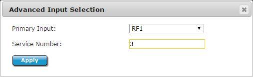
44 Web UI - Input RD Services allows input and program selection for the decoder. The IRD can be configured for Select First Found next to the given input (ASI, RF1, RF2, IP), a specific program if programs are detected or an Advanced Input selection can be made if no services have been connected to the IRD yet. Select First Found sorts the programs in numerical order and decodes the first decodable service. If a service is encrypted and the service fails to decrypt (wrong BISS key, BISS configuration OFF or non-biss encryption state), the next service will be attempted to be decoded. The IRD will continue attempting services until a decodable service is found. If the input fails or if a new input is detected, the first found mechanism will start over again. Outputting video is the #1 priority when in Select First Found mode. Click the radio button next to the desired input to Select First Found. The Reset input button can be used to clear inputs and restart the decode session. In rare cases, this may be needed if the decoder does not recover properly. The reset button will reset the decode session in a few seconds as opposed to waiting for an entire system reboot. Manual Selection occurs when the SELECT button is pressed next to a listed service. The decoder will ONLY decode the Service ID on the provided input where the SELECT button was pressed. This is live manual selection. Only services that are live are displayed in the tables. If the Service ID fails or is removed, the decoder will stop and fall to the fault mode state as configured on the Video Output tab. The decoder will resume once the Service ID is returned to a valid state. Advanced Input is available for operators who want to pre-configure the Input and Service ID when the Service ID does not exist. The advanced input is available for non-live services. When Service Number -1 is entered, the unit will be in Select First Found mode. 44

45 RF Params (LB model) 45
46 RF Params allows user to Manage RF Profiles - See RF Profiles, configure RF tuner parameters and see advanced tuner status. State - Enables or Disables the RF Input. Note: When RF1 and RF2 are both enabled, maximum tuner performance is affected. If this condition occurs, please disable one of the RF inputs. Please view tuner specifications for 46
47 symbol rate and modcod resource limitations. Downlink - Allows the operator to enter the satellite downlink frequency. The value for the Downlink frequency is used with the Local Oscillator frequency to calculate the L-Band frequency. L-Band = absolutevalue(downlink - LO). Local Oscillator - The Local Oscillator (L.O.) control specifies the frequency of the LNB local oscillator. The standard L.O. frequencies for C and Ku bands are 5150MHz and 10750MHz respectfully although, some other variants are included. If the desired L.O. frequency is not listed, select either C: Manual or Ku: Manual and enter the L.O. frequency in the Manual L.O. field. Manual LO - Allows manual entry of the LNB Local Oscillator frequency provided that either C: Manual or Ku: Manual is selected from the Local Oscillator pulldown menu. L-Band - Allows the operator to enter the L-Band frequency within the range from 950MHz to 2.15GHz. The value entered in this field is used with the Local Oscillator frequency to calculate the Downlink frequency using the following rules. If Downlink < Local Oscillator, then Downlink - Local Oscillator = L-Band. If Downlink > Local Oscillator, then Downlink - Local Oscillator = L-Band. LNB Voltage - This control is primarily used in Universal LNB applications. The LNB Polarity control allows for LNB polarization selection; the 13VDC source will select the Vertical polarity and the 18VDC source will select the horizontal polarity. For typical C and Ku band applications, the 18 VDC option is recommended. LNB 22kHz Tone - This control is used only for Universal LNB applications. A universal LNB can route the high or low band from either polarity to the IRD. The high band is selected by enabling the 22 khz tone and the low band is selected when the 0 Hz tone is enabled. Advanced Configuration - The advanced configuration section is not automatically displayed unless manual settings have been set, ie. symbol rate or DVB Type. Click the double down arrow to manually configure additional parameters. Acquisition Range - Acquisition Range is defined as the range of frequencies that the tuner will scan in order to achieve carrier synchronization. This will allow the operator to select the range of frequencies that the RF tuner will sweep through to acquire the carrier. Valid Range: 0.5-5MHz. S2X Roll-off - S2X Rolloff will allow the tuner to operate in an optimized mode for roll-offs of 15% or less. When disabled, it will operate in standard 20% - 35% as defined by the incoming S2 BBHeader. Due to modulation manufacturers providing backwards compatibility during S2 to S2X migration, this must be manually configured for the best 5%, 10% and 15% roll-off performance. Advanced Status will still show 20% as it is inserted into the baseband header by the modulator. Type - Type Allows the selection of DVB-S or DVB-S2 Demodulation Type. If AUTO is 47
48 selected, the tuner/demodulator will determine the actual modulation type. Symbol Rate Mode - Symbol Rate is defined for digital communications as the number of symbols per second. The amount of data per symbol depends on the modulation type and FEC code rate. Units for this field are expressed in MSym/s and the actual range is determined by feature key. If zero [0] or AUTO is entered, the tuner/demodulator will determine the actual symbol rate. ISI - ISI (input stream identifier) is required for multistream applications. If a multistream RF source is detected, BBHeaders containing this value will be demodulated and output to the receiver. This value has no effect during single stream applications. PLS Mode - PLS Mode determines the Gold sequence code to use for descrambling. DEFAULT (or 0), CODE1 (User entered sequence in PLS Code 1 ) or CODE2 (User entered sequence in PLS Code 2 ) PLS Code 1 - User defined PLS Gold sequence code, active when PLS Mode set to CODE1. PLS Code 2 - User defined PLS Gold sequence code, active when PLS Mode set to CODE2. RF Params (PRX model) 48
49 Active Input - Active Input determines which RF Input should be actively tuning/demodulating with the supplied parameters. Manual LO - Allows manual entry of the LNB Local Oscillator frequency provided that either C: Manual or Ku: Manual is selected from the Local Oscillator pulldown menu. Local Oscillator - The Local Oscillator (L.O.) control specifies the frequency of the LNB local oscillator. The standard L.O. frequencies for C and Ku bands are 5150MHz and 10750MHz respectfully although, some other variants are included. If the desired L.O. frequency is not listed, select either C: Manual or Ku: Manual and enter the L.O. frequency in the Manual L.O. field. 49
50 L-Band - Allows the operator to enter the L-Band frequency within the range from 950MHz to 2.15GHz. The value entered in this field is used with the Local Oscillator frequency to calculate the Downlink frequency using the following rules. If Downlink < Local Oscillator, then Downlink - Local Oscillator = L-Band. If Downlink > Local Oscillator, then Downlink - Local Oscillator = L-Band Downlink - Allows the operator to enter the satellite downlink frequency. The value for the Downlink frequency is used with the Local Oscillator frequency to calculate the L-Band frequency. Acquisition Range - Acquisition Range is defined as the range of frequencies that the tuner will scan in order to achieve carrier synchronization. Allows the operator to select the range of frequencies that the RF tuner will sweep through to acquire the carrier. e.g: If the desired carrier is at 1.080GHz and the Acquisition Range is set to 5MHz, the RF tuner will sweep through 1.080GHz ± 2.5MHz to acquire the carrier. The formula for Acquisition Range depends on the Symbol Rate. Carrier Acquisition Range (peak-to-peak) is 50kHz to 7.5 MHz. If a carrier has a Symbol Rate < 5 Mbaud, then Acquisition Range = 1.5 x Baudrate Max. If the Symbol Rate is > 5 Mbaud the Acquisition Range = 7.5 MHz max. Type - Allows the selection of DVB-S, DVB-S2 and DVB-S2X. It is recommended to use the 'DVB-S2 / DVB-S2X' mode for all S2/S2X carriers when the unit is keyed for S2X capability. Symbol Rate - Symbol Rate is defined for digital communications as the number of symbols per second. The amount of data per symbol depends on the modulation type. Units for this field are expressed in Msym/s. The default valid range is 1-54 Msym/s. For more information, contact your Adtec Digital Sales Representative. Mode - This control allows the operator to select the expected modulation mode and FEC code rate for DVB-S. In DVB-S2 / DVB-S2X modes, AUTO is the only valid setting. Rolloff - The rolloff selection will determine the shape of the input filter. This is recommended to be set to AUTO. The occupied bandwidth of the modulated signal is the symbol rate multiplied by (1+?) where alpha (?) is the rolloff factor (%). By using a lower alpha, carriers can be spaced closer together on a given transponder or an increased symbol rate can be realized for a given bandwidth. Multistream Mode - Multistream mode configures the receiver for Multistream Mode (Enabled) or Singlestream Mode (Disabled, Default). If the receiver is operating in Multistream Mode, an ISI value must be entered. Multistream ISI - Multistream ISI (input stream identifier) is required for multistream applications. If Multistream Mode is enabled, BBHeaders containing this value will be demodulated and output to the receiver. PLS Code - PLS Code determines the Gold sequence code to use for physical layer 50
51 descrambling. 0 is default. LNB State - This configuration will enable or disable power on the input connector to power the LNB. If on, the user can select the voltage and tone placed on the connector via the Polarity and Tone configurations. LNB Polarity - This control is primarily used in Universal LNB applications. The LNB Polarity control allows for LNB polarization selection; the 13VDC source will select the Vertical polarity and the 18VDC source will select the horizontal polarity. For typical C and Ku band applications, the 18 VDC option is recommended. Tone - This control is used only for Universal LNB applications. A universal LNB can route the high or low band from either polarity to the IRD. The high band is selected by enabling the 22 khz tone and the low band is selected when the 0 Hz tone is enabled. IP Params IP Params allow a user to configure IP Receive parameters and see detailed IP statistics. 51
52 IP Rx Mode - Selects where the receiver should automatically detect UDP/RTP/FEC streams (UDP/RTP), whether it is setup for TCP, ZIXI-Link or ZIXI Rx. The IRD needs rebooted when changing between TCP/Zixi and UDP/RTP and will be prompted via the Web interface. TCP and Zixi are not configurable via SNMP or Front Panel at this time. Connector - Multicast Connector setting sets the physical connector (on the rear of the unit) to use for IP receive purposes. The appropriate interface will be used based on this connector setting. Currently, IP 1 (0) and IP 2 (1) connectors are supported. Address - UDP/RTP Mode: Multicast IPA sets the multicast receive Group IP address. IP Multicast receiving is supported from compatible streamers. The range of the multicast group IP is 224.XXX.XXX.XXX to 239.XXX.XXX.XXX - Where 0 <= XXX <= 255. Note: If a unit is receiving a unicast, the address field is ignored. A value of can be 52
53 entered. Address - TCP/Zixi-Link Mode: If using TCP or ZIXI-Link, point to point modes, a value of (listening) should be entered. Stream management / transmission is done through the transmitter or Adtec encoder. Address - Zixi Rx Mode: In Zixi Rx mode, the IRD acts as a subscribing client. This address should contain the desired IP address of a Zixi Broadcaster. Port - Multicast Port is the number to be used for multicast/unicast streams. Set in conjunction with Multicast IPA. Range is 0 to If the port number is set to 0, then no UDP/RTP streams will be received. 0 is default. Source Address - Configures the multicast receive Source Specific IP Address. This configuration should be configured to (any source multicast) in most IGMPv2 multicast applications. This configuration is an advanced configuration used for redundancy, security, or IGMPv3 multicast applications. It does not function for Unicast, TCP or Zixi reception. Latency - Multicast Latency sets the latency delay before the decoder begins playback from the multicast source and should be argued as a millisecond value. The default MULTICASTLATENCY setting is 500 milliseconds. The maximum configurable range of the MULTICASTLATENCY is dependent upon bit rate (10MB buffer) with the floor configurable for 4ms. The accuracy of the actual latency compared to the configured latency is dependent upon the bit-rate and protocol used. The RD adjusts the IP reception rate to match the configured multicast latency setting and is more accurate in UDP/RTP reception. Timeout - Sets the timeout value for return to normal video playback after video multicast packets are no longer detected. The default timeout value is 300 milliseconds. If the timeout value is set too low, the multicast receive may timeout during normal reception if the packet transmission is bursty. Error Recover - Multicast Error Recovery sets the timeout value for recovery of multicast receive after decoder error condition is detected. The default error recovery timeout is configuration value is milliseconds. IP Statistics shows advanced statistics about the received stream. IP Rx Uptime, Buffer Size and DVB Per IP statistics are shown for all IP streams (UDP, RTP or TCP). The second half of IP statistics will only populate if an RTP stream is being received. If an RTP w/ SMPTE 2022 FEC stream is detected, FEC statistics will populate. IP Params - ZIXI Rx Mode Channel name is the name of the channel that is desired to be streamed. This should correspond to the Broadcaster 'Stream ID'. 53
54 Client ID is a unique identifier for this unit. It is called the remote ID on the Broadcaster. Session ID is the password for authentication to a Zixi Broadcaster. This is optional. Latency is the time given for error correction. It is recommended that latency is set higher than 3 x Round trip time. FEC Enabled turns on or off Forward Error Correction. Note that FEC uses additional bandwidth set by the Overhead. FEC Content aware allocates the FEC packets based on content. FEC Overhead is amount of FEC packets to use. This number is the percentage of your overall bitrate. For example if set to 20%, then a 5Mb stream will use 6Mb of bandwidth as 1Mb will be used for FEC. FEC Block is the maximum time given to the FEC to correct an issue. This should not be higher than half of the Latency setting. Zixi Receiver IP Statistics Data Bitrate is the currently used IP rate, this can fluctuate depending on configuration and environment. Round trip time measures how long a packet takes to travel to the broadcaster or encoder and back. This calculation is important when configuring latency and determining error correction configurations for the application. Total Packets are how many packets have been received since the IRD started receiving. Jitter is the variation in the delay of received packets. Larger jitter values could indicate network congestion and increases the likelihood of network issues being seen. Packet Rate is the amount of network packets received per second. Latency shows what the latency is set to for the service. Out of Order shows how many packets have been received out of the sent order. This can be caused by a high jitter or packets taking different routes through the network. Overflow shows the number of packets lost due to buffer overflow. Dropped shows how many packets have been lost since the receiver first locked to the service. Duplicates shows how many packets have been repeated. Recovered Packets shows how many successful recoveries have occurred out of the total 54
55 dropped packets. In a perfect application, the recovered packets plus the FEC recovered packets should be equal to the amount of dropped packets. IE, For every dropped packet, the packet was recovered. Non-Recovered Packets shows how many packets have been lost. If a packet is lost then it is possible that a service artifact or disruption could be seen. The severity of the artifact depends on the type of packet lost (Table, Video, Audio, NULL, etc.). FEC Recovered shows how many dropped FEC packets have been successfully recovered. ARQ Recovered shows how many dropped packets have been successfully recovered by ARQ. FEC Packets shows how many FEC packets have been received. ARQ Packets show how many ARQ packets have been received. FEC Bitrate shows the data rate of the FEC overhead. Duplicates shows the number of duplicate packets received via ARQ. FEC Packet Rate shows the number of FEC packets received per second. Requests shows the number of requests for retransmission of dropped packets made with ARQ 55
56 Bars Tones and ID 56

57 Bars Tones and ID allows an operator to tag the video outputs for path routing verification. The video outputs may be tagged with a combination of generated bars/color, OSD overlay and generated tones. Note: When an audio pair / channel is configured for Pass through operation (LPCM, Dolby E, Dolby D, etc.) internal tone generation does not function for the pass through channels. Advanced Tones allows the operator to mute Left/Right channels or change tone frequency. As of 2.01.XX Firmware, Bars/Tones/ID functionality has some ties to the Fault Mode configuration (Fault Mode via the Video -> Output tab). Adtec is working to break dependencies for future firmware releases. Web UI - Profiles 57

58 Profiles are specific to decoder settings (ex: Input, Video, Audio, CAS, IP Rx/Tx) and does not save RF demodulator configurations or System configurations at this time. RF demodulator profiles may be managed on units with demods via the RF Params tab. Loading a profile will restart the decoding process with the newly loaded configuration and will save that configuration for use upon a reboot. Create New - Creates a new profile of the currently saved decoder state. Load - Loads or runs the profile Delete - Deletes the profile from the unit Download - Downloads the profile to a local file Web UI - Video Genlock is used for synchronizing the SDI output to a bi-level or tri-level sync input. More can be read in the genlock section. 58
59 Mode - Configures whether Genlock should be in FREE RUN mode (OFF) or if it should lock to the incoming source (REMOTE). The Slave configuration disables audio SRCs and is to be used for special genlock applications. CVBS - Sets the Composite/CVBS output. When set to VIDEO CVBS output is video, when set to SYNC, CVBS output is black burst sync signal. SYNC is recommended if used as a master unit in special genlock applications (3D, UltraHD, Synchronous playback). Horizontal Adjust - Horizontal adjustment defines the difference in the SYNC IN HSYNC and output HSYNC. Typically, this should be in the range of 0 to +1 line in clocks. For example, a 1080I output could be adjusted from 0 to Negative values can be entered. Vertical Adjust - Vertical adjustment defines the difference in the SYNC IN VSYNC and output VSYNC. Typically, this should be in the range of 0 to +1 frame in lines. For example, a 1080I output could be adjusted from 0 to Negative values can be entered. Pixel Phase - Pixel Phase adjustment is a very fine grain adjustment that can adjust within a single clock. The increments are 1/64th of a clock. The valid range is 0 to
60 Genlock Status shows the state of the Genlock system. Video Output is used for configuring the video outputs. 3G-SDI Mapping Level - SDI 3G Level controls the mapping of the 3G-SDI signal when decoding 1080P50, 1080P59.94 and 1080P60 streams. The 3G-SDI signal can be mapped to Level A or Level B Dual Link. The mapping is individually configurable for each set of outputs (SDI and SDIALT). If 3G-SDI output does not appear on the downstream device, the device may not support the currently configured mapping mode. Use SDI3GLEVEL to change the mapping mode. Down Scaling - The SDI out scale configuration controls the format of the SDI output banks, SDI and SDIALT. Each bank has a unique configuration allowing simultaneous HD and SD output. When set to OFF, the native resolution is output. When set to SD, the output 60
61 is down-scaled dependent upon the source format. If the source format is 50Hz, the output will be down-scaled to PAL If the source format is Hz, the output will be down-scaled to NTSC Please note that there will be a 1 frame delay in the down-scaled output. Audio synchronization is accounted for automatically on scaled outputs. Fault Mode - Display or Modify the current SDI video fault setting. This setting sets the video resolution when in video fault. This setting will be applied on startup when no video is present. If video becomes present, the setting will be overridden by the current video setting. 1080P extended options are available when BIF shows BIXX (BI02, BI10). No feature key is required for this setting Fault On Video Loss - In video fault, this will define the display. STOP DECODING BLACK BARS BARS & TONES BARS, TONES & SRV ID HOLD LAST FRAME: STOP DECODING HOLD LAST FRAME: BLACK HOLD LAST FRAME:BARS HOLD LAST FRAME:BARS & TONES HOLD LAST FRAME:BARS & SRV ID HOLD LAST FRAME:BAR, TONES and SRV ID Sets RVD to STOP. Sets RVD to BLANK, and the color bar generator to BLACK. Sets RVD to BLANK, and the color bar generator to BARS. Sets RVD to BLANKTONES, and the color bar generator to BARS. Sets RVD to BLANKTONESOVERLAY, and the color bar generator to BARS. Video output will stop at boot time and will hold last frame of video and output no audio on signal loss. Video output will be black with no audio at boot time and will hold last frame of video and output no audio on signal loss. Video output will be color bars with no audio at boot time and will hold last frame of video and output no audio on signal loss. Video output will be color bars with audio tones at boot time and will hold last frame of video and output no audio on signal loss. Video output will be bars with audio and device name overlay at boot time and will hold last frame of video and output no audio on signal loss. Video output will be bars with audio and device name overlay at boot time and will hold last frame of video and output no audio on signal loss. If the "--" option is displayed when loading this tab, one of the current configuration settings is not supported. We suggest selecting a different option to properly configure your device. 61
62 OSD Mode - Controls the mode of the entire OSD engine (ON/OFF). OSD Output - Select where the OSD output will be displayed. Options are SDI, SDIALT, both, and none. The Digital Video and CVBS video outputs mirror SDI output (with the exception of Genlock -> CVBS Control, CVBS can be set to black). OSD Service Mode - Enables/Disables the OSD Service. OSD Service Lines - Defines what is displayed on the OSD services command. The format of the display is below: (1) Service Name (2) Service Provider (3) Input (4) TMR For example a value of 3 will display lines 1-3. A value of 2 will display lines 1-2. These lines can not be selected individually. OSD Service Blink - Blink is used as a bit defined field. When used with the string command it will blink the entire string not individual lines or characters. For example, binary number 1010 will blink the 2nd and 4th line of the services command. Web UI - Audio Audio allows users to manually configure audio PIDs, adjust PID order, lipsync, dolby and audio sync settings. A user will be able to configure and control 8 audio PIDs if the AUD-EXT key is enabled. 62
63 Audio Assign Order - The RD automatically assigns audio PID's to audio engines upon stream acquisition. This setting determines if the audio assignment should be done in PID Ascending order, the Adtec default, or PMT order. Some legacy IRD's use PMT order. Audio Sync Mode - Audio Sync Mode determines how the audio sub-system should behave with incoming transport streams. When it is desired for the audio subsystem to retain tight lipsync and adjust on upstream lip sync changes, this should be configured for Professional, the default setting. In rare cases, third party encoders or multiplexers may have unstable PCR/PTS timing. In these cases professional may cause intermittent drop outs as the audio sub-system attempts to retain tight lip sync. If this occurs, please change lipsync setting to Relaxed. 63
64 Audio # PID - Sets the PID for the given audio decoder. You can select one option from the list provided, or enter it manually. If entering the PID value manually, use decimal format. Valid ranges (inclusive): Valid Decimal range 0 Used to disable the audio decoder Used to set the DEFAULT PID (First Found). NOTE: No more than four passthru PID's are supported at this time. Hexadecimal values may be entered when in manual mode, but must be prepended with 0x. IE. '0x157E' and '5502'' are both valid manual entries. Offset - Adjust the audio sync offset for a given pair index with a millisecond offset value. Volume - Adjusts the value of the analog volume in db increments. The volume will attenuate, amplify or mute the audio. The valid range is -40 db to +18 dbu in ANALOG mode. Dolby Digital Mode - Sets the Dolby Digital AC3 Output format. -- Invalid Output Format 0 - PASSTHRU 2 - DECODE STEREO [compressed] (default) [2/0] NOTE : If not set to PASSTHRU and the output mode does not equal the bitstream audio coding mode (acmod), then the decoder will perform downmixing or fill channels with zero values to meet the desired output configuration. Dolby E Line - This is used to configure Dolby E placement in the SDI output and is configurable per audio engine. When set to AUTO (-1), the default configuration, the Dolby E line is placed within the valid line number range for the video resolution. The Dolby E line may be manually configured to a value within range. Valid ranges for Dolby E line placement are resolution and frame rate dependent. If the configured value is not valid, the system will use the valid line used by the 'AUTO' mode as per the Dolby table. The Dolby E line status information (in status panel) can be used to see the actual Dolby E line placement. SDI Audio Matrix allows any of the eight pairs of audio originating from the decoder to be routed to any of the eight audio outputs on the SDI interface. The matrix also allows the placement of Passthru audio on any of the 8 SDI output pairs. This enables the customization of the audio channel mappings from their default configuration. 64

65 NOTE : SDI Audio Matrix can be used for audio duplication. Web UI - CAS CAS allows an operator to configure BISS decryption and TS output configurations. Read more in the TS Out Decryption section. 65
66 Mode - CAS Mode determines which form of Basic Interoperable Scrambling System (BISS) decryption is used. [OFF] Disable decryption. [BISS_1] uses the Clear Session Word only to decrypt the transmission stream. [BISS_E_XXX] uses an Encrypted Session Word along with a User ID XXX to decrypt the transmission stream. Clear Session Word - The session keys used for decryption. [MODE BISS_1] uses a 12-digit hexadecimal Clear Session Word. [MODE BISS_E_XXX] uses a 16-digit hexadecimal Encrypted Session Word. Encrypted Session Word - [MODE BISS_E_XXX] uses a 16-digit hexadecimal Encrypted Session Word. User ID One - Valid in[mode BISS_E_ONE] ONLY. The 14-digit hexadecimal User ID used for decryption. User ID Two - Valid in[mode BISS_E_TWO] ONLY. The 14-digit hexadecimal User ID used 66
67 for decryption. TS Out Decrypt - The TS Out Decrypt configuration determines if the ASI output should mirror the selected input ( OFF ), thus preserving any encrypted streams or if it should be decrypted / free to air ( ON ). OFF, the default configuration, is recommended for users needing to redistribute transport streams in their original form. The decoder will decrypt / decode the selected program with the entered BISS key, but the ASI output will remain unaltered. ON is recommended for users needing to redistribute the ASI output as a free to air SPTS/MPTS. All programs will be decrypted with the user entered BISS key. The RD does not support BISS encrypted streams over 120Mb/s at this time. If an entire MPTS needs to be decrypted (TS Out Decrypt= ON ), the rate must not exceed 120Mb/s. If an encrypted MPTS exceeds the 120Mb/s limit, turn TS Out Decrypt to OFF, the default configuration. In this mode, the selected program will be decrypted and decoded. A single encrypted program (Video+Audio) must not exceed 120Mb/s when TS Out Decrypt= OFF. 67

68 Web UI - VBI Closed Captions - Captions are supported on CVBS, SDI, and SDIALT. To enable waveform captions on CVBS and SD-SDI, set CVBS to line 21. When set to 0, waveform captions are disabled. To enable ancillary digital 708 captions on SDI or SDIALT, select a line number next for the desired output. Teletext - Waveform and OP47 teletext is supported on CVBS, SDI, and SDIALT. To enable 68
69 waveform teletext on CVBS and SD-SDI, set CVBS to line 22. When set to 0 waveform teletext is disabled. To enable ancillary digital OP47 teletext on SDI or SDIALT, select a line number next for the desired output. VITC - Not supported at this time (2.01.XX) AFD - AFD is only supported on SDI and SDIALT via SMPTE Timecode Configuration - Not supported at this time (2.01.XX) SMPTE The Adtec decoder supports Transport Stream to SDI ancillary data pass-through via SMPTE VBI Stats shows the DID/SDID and data count for the SDI outputs if captions or AFD is enabled. The AFD code can be seen in hex and the aspect ratio flag is also displayed. Web UI - TS Output ASI Tx configures Service Filtering on the ASI Output. Read more in the Service Filtering section. ASI Filter - ASI Filter enables or disables the configured RD service filter. Service Filtering 69

70 allows users to filter or cherry pick programs destined for the output from an MPTS input. Up to 5 services can be mapped to the ASI Filtered output. ASI TS Source - ASI TS Source configures the transport stream input to ASI output routing of the IRD. ASI Output TMR - ASI Output TMR determines the ASI egress rate. When set to AUTO, the default, the output rate will be the sum of all PIDs configured for the output + minimal NULL stuffing. When set to NATIVE, the output TMR is set to match the INPUT source TMR. MANUAL is a user defined rate. Manual TMR - When ASI Output TMR is set to MANUAL, this field may be configured for a value in Mb/s. IP Tx configures IP Destinations and Service Filtering for the IP Outputs. A summary table of active configuration can be seen when visiting the IP Tx tab. Click edit next to the desired destination to configure parameters. Read more about protocols in the IP section. 70
71 IP TS Source - IP TS Source configures the transport stream input to IP output routing of the IRD. NOTE: This is a GLOBAL IP setting. IE, Each IP destination can have it s own set of filtered programs, but each program set must come from the same TS input source. Multicast Mode - Multicast can be turned OFF or set to SEND mode. SEND Mode transmits the current encode via the GigE port. Multicast group IP and Port addresses must be specified. Unicast Gateway - The Unicast Gateway automatically handles IP routing for unicast transmissions. This must be configured if the outgoing unicast requires a different gateway from the configured system default gateway. A route is automatically added when the unit is configured for transmit and a Unicast Gateway exists. The route is deleted if set to or Multicast Mode set to OFF. NOTE: An unwanted route removal corner case exists at this time. This can occur for applications requiring the same send IP address and the same unicast gateway IP for more than one destination. When one of the mirrored destinations is disabled the shared route will be deleted. If this type of application is required, only use one Unicast Gateway for the group of matching send IP addresses. 71
72 IP Tx Mode - IP Tx Mode controls the protocol used for transmitting a transport stream over IP. UDP / RTP or TCP. More information can be read about these in the IP section. RTP - RTP allows for sequence numbering and timing, which are crucial for the accurate playback of an audio or video data stream. Note: This field may be edited if Multicast Mode is set to SEND and IP Tx Mode is set to UDP/RTP. Multicast IPA - The IP Address of which the Multicast or Unicast is broadcast. Multicast addressing supports the transmission of a single IP datagram to multiple receivers. Valid Multicast addressing range is XXX.XXX to 239.XXX.XXX.XXX. Unicast addressing sends a single IP datagram to only one receiver. The Unicast address will be the unique IP of the receiving device. Note: Either a Multicast or Unicast address may be entered into this field when Multicast Mode is set to SEND. Multicast Port - Port number are used for sending UDP transfers in conjuction with Multicast IPA. The valid range is If the port number is set to 0, then no UDP transfers will take place is default. Note: This field may be edited if Multicast Mode is set to SEND. Type of Service - Type of Service helps define how the network should make negotiate queuing between throughput, delay, reliability, and cost. Time-to-Live - Time to live is a numeric value from 1 to 255 that specifies the number of iterations or transmissions the packet can undergo before it is discarded. The default value is 7. FEC Mode - T he Forward Error Correction technique implemented in this encoder conforms to the SMPTE standard for the carriage of real-time Video/Audio content over IP networks. When enabled, the encoder will send two FEC streams to the same destination IP address as the source stream, using destination port plus two and destination port plus four. The FEC requires two parameters, L and D, affecting FEC bandwidth and recovery capacity. The standard places three restrictions on these parameters; L is greater than or equal to 4 and less than or equal to 20, D is greater than or equal to 4 and less than or equal to 20, and the product of L and D is less than or equal to 100. NOTE: RTP must be ON before FEC streams start. FEC streams IP TTL matches the source stream. DVB Per IP - DVB per IP configures the amount of DVB 188 Byte Transport Stream packets for an IP packet payload. 1 DVB packet per IP packet has the lowest impact on service interruption if 1 IP packet is lost, however it has the highest data overhead due to packing inefficiency. 7 DVB packets per IP packet has the highest impact on service interruption if 1 IP packet is lost, however has the lowest data overhead due to packing efficiency. 4 DVB packets per IP packet is a compromise between efficiency and service impact. 7 DVB packets per IP packet is the default value and recommended for most applications. 72
73 Multicast Connector - The multicast connector configuration determines whether the IP stream will be sent out the IP1 (0) or IP2 (1) port. IP Destination # TMR - IP Destination TMR determines the IP transport egress rate for the specified destination. MANUAL is a user defined rate. NOTE: This value is only selectable if the SVC-FLTR-KEY is enabled. Manual TMR - User defined IP TMR in Mb/s. IP Filter - IP Filter enables or disables the configured RD-70 service filter. Service Filtering allows users to filter or cherry pick programs destined for the output from an MPTS input. Up to 5 services can be mapped to the IP Filtered output. NOTE: This value is only selectable if the SVC-FLTR-KEY is enabled. Web UI - System System allows setup of Network, SNMP and Date/Time configurations. The system may also be rebooted from this tab. 73
74 Device Name - Device name is the host name for the unit. When a unit is manufactured, it is given a name that combines the product type and the serial number of the unit. Ex. ProductName This name is broadcast to local subnets. By using the built-in Bonjour locator in the Apple Safari browser or the plug-ins readily available for Internet Explorer or Firefox browsers, you can locate Adtec Digital devices via serial number or custom name. Gateway Address - Gateway IPA is an address on a TCP/IP Network that serves as an access point to another network. Each Adtec Digital device is limited to one Gateway IPA. Nameserver IP - NAMESERVER is used to manage connectivity to network attached 74
75 storage. Setting NAMESERVER may conflict with DHCP which acquires NAMESERVER automatically. Do not set NAMESERVER when DHCP for IP1 is active. DHCP - Enables your device to extract an IP Address from a DHCP server for use as the Ethernet IPA for the IP 1 port. The overall purpose of this is to reduce the work necessary for administration of a large IP network. Consult your Network Administrator before using DHCP. This setting requires the presence of a DHCP server on the LAN. The DHCP server needs to be able to notify a DNS server of the IP address associated with the unit name (which is the Device Name). IP Address - The Internet Protocol (IP) Address used for the IP # port of the device. The device's IP address must adhere to certain standards and not conflict with the IP address of any another device on the network. IP address(es) with 0 or 255 in them are invalid. Please consult your organization's Network Administrator before assigning an IP address to a unit. An IP address of can be assigned and will effectively disable the unit's network capabilities. Subnet Mask - The Subnet Mask sets the network subnet mask assigned to the unit. Consult your organization's Network Administrator for the IP Subnet mask for your unit(s). MAC Address - Displays the units physical MAC address. Link Status - Displays whether the connector detect link or not. Link Speed - Displays the connected link speed if the link is up. NTP Address - NTP Address is the IP address of an external source for time. It should be entered in decimal form XXX.XXX.XXX.XXX. Setting the NTP Address to turns NTP off. Time Zone - Time Zone is used to specify the name of your timezone, the offset is in hours from UTC and a Daylight Savings Setting. Date - This field will auto-populate if your device is networked to an NTP server; it can also be used to manually designate a time-of-day for timekeeping and internal scheduling. Time - This field will auto-populate if your device is networked to an NTP server; it can also be used to manually designate a time-of-day for timekeeping and internal scheduling. SNMP - Controls the status (ON/OFF) of the Simple Network Management Protocol (SNMP) feature. We support SNMPv2c version. Read Only Community - The Simple Network Management Protocol (SNMP) Read-Only Password. Default Value: "adtec" Read Write Community - The Simple Network Management Protocol (SNMP) Read-Write Password. Default Value: "none" 75
76 Trap Community - The Simple Network Management Protocol (SNMP) trap community. Default Value: "public" Trap Sink Address - The Simple Network Management Protocol (SNMP) trap sink. Default Value: " " Web UI - Security See the Web UI Authentication article for information on Security. Web UI - Upgrade Upgrade Firmware See the Web UI Upgrade article for information on unit and demodulator firmware upgrades. Upgrade Features See the Web UI Features article for information on unit and demodulator feature keys. Web UI - Help Help provides an HTML version of this manual, firmware release notes, API notes, SNMP MIBs and licenses used in making the product. API Interface The API or Application Programming Interface is an advanced interface to interact with Adtec products. This interface is available for special cases such as system integration, network management systems (NMS), advanced troubleshooting, developers and testers. An operator does not generally interface with the API directly, but instead will interface with third party software. If an operator does need to interface with the API, generally it will be for troubleshooting purposes with the aid of a support representative. API commands and documentation can be found on the Help tab of the product and the Adtec Digital website. The API is available both via network (Telnet) and serial (COM2) connectivity. Telnet (standard 23 port) To connect to an Adtec unit using a terminal session, the IP address of the unit must be known. See earlier instructions on setting IP address via the front panel. Windows XP, MAC and Linux Instructions: Using a terminal window, complete the following: Step Action 1 Type 'telnet x.x.x.x' in a terminal window, without quotes, where x.x.x.x is the IP address of the unit. 76
77 2 Press <Enter>. 3 When prompted for a username, enter adtec. 4 When prompted for a password, enter none. Once the prompt "User 'adtec' connected" is seen, the session is open and API commands are ready to be entered. Microsoft Windows 7 and higher may have telnet disabled by default. An operator may enable telnet or they may download a third party program. PuTTY is a popular API program that offers both network and serial control options. To enable the default telnet client installed on Windows 7 or higher: Step Action 1 Click on Start -> Control Panel 2 Click on the Programs category 3 Click Turn Windows features on or off under the Programs and Features catgegory 4 Place a check mark inside of Telnet Client and click OK 5 Please be patient as Windows enables Telnet capability, it can take several minutes. SNMP Interface The SNMP or Simple Network Management Protocol interface is an advanced interface to interact with Adtec products. This interface is available for special cases such as system integration, network management systems (NMS) and developers. Third party software is usually written around this interface so users may interact with the product. An operator does not generally interface with SNMP directly, but instead will interface with third party software. SNMP MIB s (Management Information Base) that describe the interface can be found on each product s Web interface under the Help tab. RD Web UI Authentication and Security Features Summary 77
78 Adtec products provide flexible web authentication and security features so they may thrive in unique and dynamic broadcast environments. Adtec has recently added ADVANCED UI authentication to allow administrators without external control systems provide unique read/write Web UI capabilities for each individual web operator. Web UI authentication can also be turned completely OFF in environments where password security is not required. Adtec products also offer capability to change the listening web port to prevent external port 80 attacks, turn off management from the IP2 port and add a STEALTHIP or safe list of allowed IP addresses to access web/ftp/telnet services. This document will describe Web UI authentication behaviors and the available security features. Web UI Authentication Modes The Web UI authentication can be configured to operate in one of three modes. OFF - No authentication is required. When set to OFF, all users that navigate to the web interface will be granted admin privileges and will be directed to the home page when typing in the IP address of the unit. The home page is the Input -> RD Services page on RD products and the Services -> ASI Transport for EN products. ON - Default behavior. All users that navigate to the web interface will be directed to a Splash page that consists of a Proceed to Login button, support links and information about the unit including serial Number and firmware version. The admin username is fixed at adtec and can not be changed. The default password is none, but may be changed via the Security -> Password configuration. This password changes all services including Web UI, FTP and Telnet. 78


79 Log on Splash Screen when set to ON ADVANCED - All users that navigate to the unit will be prompted with a username and password Login box. As of date 8/28/2015, the default username is adtec and the default password is none for the administrator. This password is stored differently than when in the ON mode and defaults to none, regardless of previously changed passwords when set to the ON configuration. The Login as Guest button may be used to view the Web UI in read only mode. Web UI Authentication Advanced mode 79
 that is able to access all tabs. Create a user: Step Description 1 Click the Add User button to add a custom user.")
80 Users with write access get administrative controls and are allowed to change any configuration available in their view mode. It is recommended to keep one admin user (adtec or other) that is able to access all tabs. Create a user: Step Description 1 Click the Add User button to add a custom user. 2 Fill in the desired username 3 Fill in the desired password for the new user 4 Verify the user can login by setting the Active configuration to YES 5 Choose read only or write Access by configuring the Write Access configuration to YES (write) or NO (read only). 6 De-select tabs that are not desired to be viewed by the new user. IE. If the Security tab is grayed out, the newly created user will not be able to navigate to the Security tab. Sub-tabs can also be chosen. 7 Click Apply and share credentials with the desired user/operator. user1 without navigation capability to System, Security or sub-tabs of TS Output User administration is possible for all users with Write Access to the Security page. The adtec and guest users are default users and can t be deleted, but they may have their permissions modified. 80

81 When the user1 operator logs in, they will only see tabs configured for them. example: user1 is does not view System, Security, RD Services, RF Params and Bars Tones & ID tabs after login as configured If a user has Write Access configured to NO, user will receive permissions error when attempting to change any values. Other security features HTTP Port The Web UI listening port or HTTP Port may also be changed to prevent unwanted users from finding the Adtec web interface at the default port. If the port is changed, the web address for login will need updated. For example if the unit IP address is , standard web navigation can occur by typing in the browser address bar. If the port is changed (to 8000 for example), then user would need to type to navigate to the unit. All requests on default HTTP port 80 would be denied. Stealth IP address The Stealth IP address feature allows up to 4 IP addresses as a safe list. Any IP addresses listed in the safe list are allowed to enter the box. Any IP addresses that aren t listed will be denied all access. When enabling this feature, it is recommended to enter the IP address of the 81
82 PC configuring the unit with first. Otherwise, you will be locked out. The Stealth IP address feature only supports IPv4 addresses at this time. IP2 / GigE Management By default, the IP1 (eth0) ports of Adtec products are reserved for management and the IP2 (eth1) ports are reserved for Transport Stream I/O. The ports can be used for either management and/or transport with the Multicast Connector configurations on TSoIP Rx and Tx pages. To prevent unwanted users from managing the device through the IP2 port, an IP2 Management configuration has been made available on the System tab. This defaults to ON (allow management from both IP1 and IP2 ports), but may be turned to OFF (only allow management from IP1 interface) to further secure the device. Turning this feature OFF disables Web UI, FTP and Telnet connectivity on the IP2 port. Operational Information DVB-S / DVB-S2 AUTO Modes The RD-71 with L-Band demodulator (LB) option supports automatic detection of modulation type and symbol rate on two RF inputs. In fully automatic mode, the minimum configuration requirement is L-Band frequency. The demodulator is running in fully automatic mode when the type is set to AUTO and the symbol rate is set to 0 or AUTO. Notes about demodulator: Please note that some carriers may not fully acquire if they fall outside of the allocated resources available by the hardware. Please reference the demodulation resource table located in the appendix for supported modes. DVB-S2 - Recommended use of Pilots The use of DVB-S2 pilots within the modulated carrier are recommended under certain conditions. With the following configurations, Pilots are recommended: High order modulation schemes: 16APSK and 32APSK Low code rates QPSK: 1/4, 1/3, 2/5, 1/2, and 3/5 Low code rates 8PSK: 3/5, 2/3, 3/4, and 5/6 Low symbol rates: <5 Mbaud for free running DRO LNB Low symbol rates: <3 Mbaud for Phase Locked DRO LNB Single Stream (no restart)-prx only model Multistream Mode: **If there is any encoder/modulator rate mismatch there can be TS errors, Single Stream (no restart) should be selected** 82

83 RF Profiles The RD has capability to create profiles from the current running RF configuration and load it at a later time. To create a profile: Enter the desired RF parameters required for the profile Click the Apply button to save information to the currently running configuration Click the Create RF Profile button next to the respective tuner that is desired to be stored. Name the RF Profile and click OK. Please note that only Alphanumeric and underscores are allowed in the profile name. If Spaces, Dashes -, or other special characters are entered, an error window will pop up. All drop downs will populate with the created RF profile name To load a profile: Select an RF profile from the Select Profile list above the desired tuner. After selection, the profile will be previewed and all configuration fields will display the contents of the profile. If the profile is desired to be loaded into the respective tuner, click the Apply button. If the profile is not desired, the Cancel button may be clicked or the double dash profile -- may be selected to exit from preview mode. Exiting preview mode will return to display the current running configuration. Profile Management: The Manage RF Profiles box gives users the ability to Delete (Red X button) or Download (Downward Yellow button) RF Profiles from the IRD. Select a Profile and click the Delete button to have the profile removed from the device and all drop down boxes. Select a Profile and click the Download button to have the profile downloaded to your PC. The standard Upload button next to the Logs and Thumbnail button may be used to 83

84 Upload a profile to other devices. UDP / RTP / FEC / TCP IP Rx The RD-71 supports a number of IP based protocols for the reception of transport streams via private and public networks. The RD-71 will automatically determine if an IP stream is UDP, RTP, or a SMPTE-2022 FEC stream. TCP reception is a less common implementation for transmission of broadcast transport streams, but has recently been added to the RD-71. UDP ( User Datagram Protocol ) multicast/unicast streams are commonly used for broadcast transport streams in local or private networks that contain little to no packet loss. UDP offers no protection against dropped packets or packets received out of order (usually due to packets taking a different amount of time to traverse network devices). Due to the low reliability of UDP, it is NOT recommended to be used over the public internet or in environments where the potential of packet loss, increased jitter, or out of order packets is high. If packets are lost or received out of order, service anomalies will occur. The RD-71 supports up to 100Mb/s when a 7 DVB Packet payload exists for each UDP packet. RTP ( Real-time Transport Protocol ) is another type of multicast/unicast stream that is better to use than UDP in some environments. RTP is built upon the building blocks of UDP, but adds packet sequence identification. Packet sequencing gives a receiver the information needed to detect and correct packets that were received out of order. RTP is highly recommended when timely delivery of each consecutive packet may not be guaranteed. The RD-71 supports up to 100Mb/s when a 7 DVB Packet payload exists for each RTP packet. RTP + FEC or SMPTE-2022 is an additional method used in dealing with lost packets, where RTP alone can only tolerate packets received out of order. FEC ( Forward Error Correction ) streams add overhead to the overall data rate, but add protection in case of a lost packet. FEC ( detection and correction of lost packets ) adds latency and data overhead as opposed to UDP where no protection mechanisms exist. The amount of packet redundancy and overhead can be configured at the RTP/FEC transmitter. Each multicast/unicast FEC stream is transmitted on base port N and two FEC streams are sent on N+2 and N+4 respectively. When receiving FEC streams behind firewalls, please bear in mind that two additional ports ( 84
 support, a connection based protocol, has recently been added at an attempt to overcome some of the fundamental limitations of UDP and RTP.")
85 N+2 and N+4 ) must be allowed through for proper error recovery to occur. The RD-71 supports up to 45Mb/s SMPTE-2022 when a 7 DVB Packet payload exists for each RTP packet. TCP ( Transmission Control Protocol ) support, a connection based protocol, has recently been added at an attempt to overcome some of the fundamental limitations of UDP and RTP. UDP and RTP are one way street types of protocols where the transmitter sends data and never knows if the data makes it to the destination. TCP streams generally have higher latency ( takes longer to transmit data and verify data has been transmitted ), but are more reliable because each packet is accounted for by the receiver. If a packet is lost, the transmitter will be informed to re-transmit the packet. The transmitter and receiver continue to communicate about the quality of the reception and attempt to adjust packet delivery accordingly. The TCP mechanism when combined with large IP receive buffers can be more forgiving with packet loss, jitter, and out of order packets. The RD-71 supports up to 15Mb/s when a 7 DVB Packet payload exists for each TCP packet. Multicast is not supported with TCP streams. The RD-71 supports both unicast (point to point) and multicast (broadcast) streams. The RD-71 operates in UDP/RTP mode by default. To setup an IP Rx session, first configure the IP Rx operation mode. A unit reboot is required (WebUI asks for confirmation when changing) when changing between UDP/RTP Rx and TCP Rx modes. Multicast Reception - Address To receive a multicast (UDP/RTP/SMPTE2022) stream, place the multicast address wished to view in the Address field. This address must match the same address used on the multicast transmitter. Multicast IP address ranges are 224.xxx.xxx.xxx to 239.xxx.xxx.xxx, where 0 <= xxx <= 255. If you are new to multicast and attempting a first time connection, is a common address to start with. Please verify transmitter address 85
86 configuration. Optionally, the source specific multicast address (The actual IP address of the sending device) may be entered for IGMPv3 applications. Configuring the Source Address will allow multicasts to be received from the entered address and entered address only. This configuration is non-functional for Unicasts. For IGMPv2 applications, the source address recommendation is Unicast Reception - Address To receive a unicast (TCP/UDP/RTP/SMPTE2022) stream, enter in the Address field. The unit will be listening for any streams sent directly to it. Refer to your IP transmitter documentation for proper configuration of the transmitter. Unicast/Multicast Reception Enter the port number in the port field. The port number must match the port number used on the transmitter where the range is 0 to When 0, multicast is disabled. If you are new to multicast and attempting a first time connection, 2000 is a common port to start with. Please verify transmitter port configuration. Choose the IP Rx Connector dependent upon network setup. Once IP Rx is configured, click Apply. Visit the Input -> Service tab and click the Select first found radio button to enable IP reception. IP service names will populate in the service list. 86
![Select first found is also available via the Front Panel -> Services Menu -> Select First configuration. Use the left/right arrows to select [IP], press select, then press enter to start IP receiving.](/docs-images/74/69696432/images/87-0.jpg "Dolby E, Dolby D, LPCM, and Mpeg 1 Layer 2 As of 0.01.")
87 Select first found is also available via the Front Panel -> Services Menu -> Select First configuration. Use the left/right arrows to select [IP], press select, then press enter to start IP receiving. Dolby E, Dolby D, LPCM, and Mpeg 1 Layer 2 As of firmware, the RD-71 supports 16 channels of SDI embedded audio output with support of up to four audio pass-throughs, up to 8 pairs (sixteen channels) of aligned Mpeg 1 Layer 2 audio, and up to 8 pairs of Dolby Digital decoding. An audio pass-through consists of a Dolby E 20 Bit, Dolby E 16 Bit, Dolby Digital, or a Linear PCM stream that is preserved (not decoded) from the transport stream and embedded on the SDI output. Mpeg 1 Layer 2 decode support includes 48kHz kbps. Interoperability support includes stream type 0x03 (sometimes called Mpeg 1 Layer 2), stream type 0x04 (sometimes called Mpeg 2 Layer 2), PES aligned/unaligned audio, Mono ( with audio duplication feature ), Dual Mono, and Stereo decoding. Dolby Digital decode support includes a stereo output pair for each Dolby Digital Audio PID assignment ( multi-channel Dolby Digital 5.1 for example is down-mixed to 2/0 ). 87
88 Note: Encoder must support alignment for aligned audio feature. The RD-71 automatically configures the audio engines upon acquisition of a program when engines and sdi matrix are configured to AUTO. The audio is automatically output based on ascending audio PID order from the selected program, not PMT order, to retain encoder compatibilities. The left hand status panel of the Web UI shows current active SDI audio output. Advanced configuration is available via the Audio tab for users that need to select custom PID s, disable audios, and duplicate audio pairs. Dolby E line placement is handled automatically to meet Dolby Labs specification. Some users may need custom line placement. If the customer Dolby E line placement selection is out of specification, the RD will revert line placement to the automatic in range value. Please see table in notes for Dolby E line placement recommendations. Notes: Encoder must support alignment for aligned audio feature. Pass-through audio bit-rates are now displayed on the left hand status panel. Please note that these are live calculated bit-rates and will not show a static number. 88
89 Dolby Labs - Dolby E recommended line position table i p p i p p Earliest Ideal -80us Ideal +- 80us Ideal +80us Latest Adtec Auto
90 AFD - Active Format Description Active Format Description (AFD) contains aspect ratio and handling information utilized to aid in picture presentation of downstream devices. This is used most often by down-converters and set top boxes. AFD carriage can be carried within a transport stream as a unique ANC PID (ancillary pid), within the video elementary stream as SEI data (H264), or user data (MPEG2). The RD-71 does not support AFD via an ANC PID at this time. The RD-71 AFD implementation preserves the native AFD code from the video elementary stream and is inserted into the SDI ancillary data output on DID/SDID 0x4105. The SDI output is not modified in anyway based upon this data. SDI line number for AFD carriage is configurable via the VBI tab. The DID/SDID, AFD code, and aspect ratio flag can be seen in the VBI Output table via the VBI tab. 90
91 Genlock System The RD-71 can synchronize its SDI and CVBS outputs to an external sync signal using the SYNC IN input and the Genlock control system. The SYNC IN input signal's frame synchronization is used to generate SDI and CVBS output pixel clocks, frame synchronization and audio clocks that are locked to the SYNC IN reference. The video decoder will automatically skip or repeat video frames as needed to adjust to differences between the SYNC IN clock and the decoder source clock (which is synchronized to the stream's PCR data). The audio system uses a sample rate converter to adjust to differences between the decoder source clock and the SYNC IN clock. The Genlock system will automatically cross lock for all resolutions within the Hz standard or all resolutions within the 50 Hz standards. It does not cross lock between 50 Hz and Hz standards at this time. This allows the SYNC IN signal to be valid for compatible decoded streams (example: An NTSC black burst SYNC IN signal can be used to Genlock a 1080I59 feed). The Genlock system can be configured in two modes. Genlock SLAVE mode is used when the SYNC IN signal is synchronous with the decoded stream, ie, both signals are using the same 27 MHz source clock. This mode allows two RD-71's to be used for receiving 3D/4K signals or when the decoded source is using the same clock base as the SYNC IN. This mode bypasses the need for the audio sample rate converters. Genlock REMOTE mode is used when the SYNC IN signal does not use the same 27 MHz clock source as the decoded stream. This mode enables the audio sample rate converters for audio output. The SYNC IN input will accept standard analog video sync for NTSC, PAL, 480I/P, 576I/P, 720P, and 1080I/P from Composite Video (CVBS). The input can accept Bi-level and Tri-level sync signals. The signal is processed to create synchronous audio and video clocks and to frame align the SDI and CVBS outputs with the input sync signal. Generally, the output will be automatically aligned within a few pixel clocks of the input. If the Genlock system is locked, and the SYNC IN is removed, the system will attempt to maintain the clocks and frame reference with the last known locked frequency. There may be some clock drift over time. If the decoder is stopped and restarted in this mode, the Genlock system will use the decode source clock and operate in a 'free-run' mode until the reference is re-applied. The video and audio will be lost for a short time when the SYNC IN reference is restored. When the Genlock mode is changed, the Genlock system will automatically be reset. This will cause a brief disturbance of the video and audio outputs. 91
, thus preserving any encrypted streams or if it should be decrypted / free to air (ON).")
 where the user wants to preserve encryption on the ASI output, but also")
92 TS Out Decrypt TSO or Transport Stream Out Decrypt determines how BISS encrypted transport streams are processed. This configuration provides end users flexibility on how the RD is used. The TS Out Decrypt configuration determines if the ASI output should mirror the selected input (OFF), thus preserving any encrypted streams or if it should be decrypted / free to air (ON). TS Out Decrypt should be set to OFF, the default configuration, if the IRD is to be used in a confidence decode / turn around application. A confidence decode / turn around application can involve the IRD being used a turn around device (IP to ASI or RF to ASI) where the user wants to preserve encryption on the ASI output, but also wants to decode one of the incoming programs. This configuration also allows the RD to ingest encrypted MPTS streams that may be over the TSO limit. A sample diagram of how the transport stream is passed to the ASI output through the system is shown below. If the user wants to use the IRD as a decoder and decrypter, the TS Out Decrypt configuration should be set to ON. All programs will be decrypted with the user supplied BISS key and transported to the ASI output. This application is useful for users that want to redistribute the stream to other non-biss devices, such as transport stream analyzers or third party decoders. Please note that when in this mode, total transport stream throughput must not exceed the rate stated in the Technical Specifications found in Appendix B. 92
 or several programs (MPTS, multiple program transport stream, also known as MCPC.). PAT - Program Association Table.")
93 Service Filtering Terminology: TS - Transport Stream - A stream of transport packets that contain audio, video and data belonging to one (SPTS, single program transport stream, also known as SCPC.) or several programs (MPTS, multiple program transport stream, also known as MCPC.). PAT - Program Association Table. This MPEG-2 table lists all the programs contained in the transport stream and shows the PID value for the PMT associated with each program. The PAT is always found on PID 0x0000. PMT - Program Map Table. This MPEG-2 table specifies PID values for components of programs. PID - Packet Identifier. This unique integer value identifies elements in the transport stream such as tables, data, or the audio for a specific program. Program / Service / Channel - A combination of one or more elements (video, audio or data) defined by a PMT. Summary: Service Filtering allows an MPTS from the input to be turned into an SPTS or program reduced MPTS on a given output. This is helpful in service turn around applications where all programs are not desired for re-transmission. An example of 5 MPTS to a smaller MPTS output is shown below. The Adtec RD-71 also has the ability to route Inputs to Outputs, such as route RF2 Input to ASI Output while decoding from RF1. The Service Filter control must be ENABLED for routing to function. The RD-71 does not support multiplexing of the inputs. A block diagram of the input routing and filtering is shown below. Input to Output Routing and Filtering 93
94 The SVC-FILTR key must be enabled to configure Service Filtering. When filtering is enabled, a maximum of 5 programs are allowed on any given output. If filtering is disabled, all programs available on the selected input for decode are available on the output, ie. unit is in service pass through mode and no longer routing. Configure Service Filter on ASI To configure service filtering on the ASI output, visit the TS Output -> ASI Tx tab. First choose the ASI Output Source. The ASI Output can be sourced from ASI IN, RF1 IN or RF2 IN, depending on demodulator hardware option. Then, choose the ASI Output behavior or ASI Output TMR. ASI Output TMR determines the ASI egress rate. When set to AUTO, the default, the output rate will be the sum of all filter PIDs configured for the output + minimal NULL stuffing. When set to NATIVE, the output TMR is set to match the INPUT source TMR. MANUAL is a user defined rate. Then, choose the service required to filter from the Available Service list. Clicking the right arrow will add the service to the Assigned Service list. When the ASI Filter is set to ENABLED and Apply is clicked, you shall now see the selected service on the ASI Output. 94
95 Firmware Upgrade via Web User Interface Periodically, we will provide firmware updates to our products via our website. ( To upgrade your device, download the firmware file from our website and store it locally. Login to the web-based application and navigate to the Upgrade > Firmware tab. Click on the upload button located at the top right of the application. Select the firmware file from your local machine and wait for it to upload. Once it has finished uploading, it will appear in the Available Versions list. 95

96 Click on the Install button associated with the new file. Wait for it to completely extract and become available in the Installed Versions List. Once available there, simply click on the Select button associated with the new firmware and wait for your device to reboot. Demodulator Firmware Upgrade via Web User Interface In some cases, Adtec may provide a modulator or demodulator firmware upgrade. These are handled separately than standard product firmware upgrades because they can take longer than a product firmware update and should be planned during maintenance windows. Adtec currently has several demodulator versions that include ADV, LB and PRM models. Each demodulator hardware type has a unique demod firmware version and must be upgraded with a compatible version. To upgrade, first determine the installed demodulator type and firmware version. Visit the Upgrade -> Features tab. The BOARDS INFO table slot 99 will contain the installed demodulator version. The above example shows a PRM demod running demod version In this case, a 7044AB firmware file name is required to update this demodulator. If a demodulator firmware is provided for any reason, please make sure the firmware type provided matches 96

97 the hardware type of the unit it is being installed on. The demod firmware may be upgraded similarly to a product firmware upgrade. Click on the upload button located at the top right of the application. Select the firmware file from the local computer and wait for it to upload. Once it has finished uploading, it will appear in the Available Demodulator Versions list. The time required to update firmware varies on hardware model and should be accounted for during the maintenance windows. Estimated Time required to update firmware: LB Demod firmware update - ~6 minutes Once the version is seen on the Upgrade -> Firmware tab, click SELECT to start the upgrade process. A status bar will appear and will progress as the firmware update commences. When the firmware update is complete, reboot the unit and verify the firmware version again on the Upgrade -> Features Tab. 97

98 !!NOTE!! It is only recommended to update during a planned maintenance window. If a firmware upgrade fails for any reason, it is OK. Just try the upgrade again by clicking on the SELECT button. The upgraded version can be verified by visiting the Upgrade -> Features tab after reboot. It is recommended to delete the file after a successful upgrade by clicking the DELETE button. 98
99 In Field Feature Upgrades Unit features can be upgraded in the field via the web user interface. Keys can either be temporary (feature will stop working after a set amount of time) or permanent (key is good for the life of the product). To purchase a permanent key, please provide the unit serial number and product ID from the Upgrade -> Features tab to your sales representative. If a temporary key is required, the Temporary ID will also be required. Permanent Key Instructions A permanent unlock key can be provided via or verbally if internet access is not available. To enter the unlock key: Step Action 1 Click on the Input Key button next to the desired feature. 2 Enter the supplied key into the pop-up dialog box and click OK. 3 The feature status should change from DISABLED to ENABLED. 4 In some cases, a reboot of the unit may be required after a state change to ENABLED. Reboot unit if enabled feature does not function. 99

100 Temporary Key Instructions If a temporary key is provided, it will be in the form of an attachment or file. Temporary keys are not entered through the Input Key button. Instead, they are transferred to the unit through the use of the file transfer utility via the Upload button. The Upload button is found in the top right hand corner of the Web UI. Step Action 1 Download the temporary key file to your computer provided by your representative. 2 Click on the Upload button in the top right hand corner of the Web UI. 3 Browse for the supplied ASC file from the file browser pop-up and click Open 4 The page should reload and feature status should change from DISABLED to ENABLED with a Days Left count. This count determines how many days the key will function before returning to a DISABLED state. 5 In some cases, a reboot of the unit may be required. Reboot unit if enabled feature does not function. 100
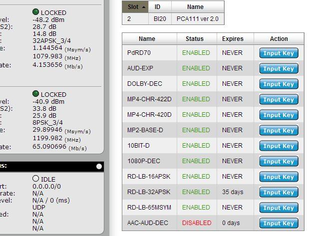
101 101
102 RD-71 Zixi Setup Guide Where previous protocols, such as TCP, UDP and RTP have various constraints, Zixi is designed to overcome protocol limitations for broadcast quality video delivery. There are two Zixi options available on the RD-71, Zixi-Link and Zixi-Receive. Zixi-Link is a point to point IP transport using Zixi technology to provide reliable video service over nondeterministic networks. If the IRD is behind a firewall, port forwarding is required. In this mode, Zixi parameters are configured on the sender (or Adtec encoder). Zixi-Rx is used in point to multipoint applications and is combined with a Zixi Broadcaster server. In ZIXI- Rx mode, the IRD is acting as a client and can therefore bypass the need for firewall forwarding rules to the IRD. In this mode, all Zixi parameters are configured on the receiver (or RD-71). Zixi uses a combination of FEC and ARQ to deliver packets. The amount of latency between end-points, the amount of packet loss incurred between end-points and the bandwidth requirements of the link all affect how the FEC and latency settings should be configured. These three items should be taken into consideration when doing initial setup. Setting up Zixi-Link To use Zixi-Link, the feature key must be enabled. This may be verified on the Upgrade -> Features tab. If the key is not enabled please contact your sales representative, sales@adtecinc.com. Select ZIXI-Link under IP Rx Mode. The Web interface will prompt for a reboot confirmation, click Apply. Once the unit is back up, select the correct Connector for the IP input, the default is IP2. 102

103 As ZIXI-Link is a point to point transport input into the Address field. Then input the correct port that the Zixi Feeder is set to. Default is Then click Apply. Via the Inpu -> RD Services tab, select the Select first found radio button next to IP. If all settings are correct then the Zixi stream should appear and start decoding. Setting up Zixi Rx To use Zixi-Rx, the feature key must be enabled. This may be verified on the Upgrade -> Features tab. If the key is not enabled please contact your sales representative, sales@adtecinc.com. Select ZIXI Rx under IP Rx Mode. The Web interface will prompt for a reboot confirmation, click Apply. Once the unit is back up select the correct Connector for the IP input, default is IP2. Input the Zixi Broadcaster Address into the Address field, along with the Port in the Port box. The default port for the Zixi Broadcaster is
10-bit 1080P Integrated Receiver Decoder. v
 RD-71 10-bit 1080P Integrated Receiver Decoder USER GUIDE v2.00.18-08.10.2015 1 Contents Contents Introduction Rack Installation Back Panel DB9-M Analog audio output pinout COM1/COM2 to DB9 Serial Adapter
RD-70. USER GUIDE v bit / Multi-CODEC 1080P Receiver / Decoder. Includes demodulator versions - ADV, LB and PRM
 RD-70 10-bit / Multi-CODEC 1080P Receiver / Decoder Includes demodulator versions - ADV, LB and PRM USER GUIDE v2.02.21 Contents Contents Trademarks & Copyrights Electrical Device Compliance Notices Safety
Multi-CODEC 1080P IRD Platform
 Multi-CODEC 1080P IRD Platform RD-70 The RD-70 is a 1080P multi-codec very low latency MPEG 2 and MPEG 4 AVC/H.264 high definition IRD. The ultra-low delay mode requires the use of Adtec s EN-91 1080i,
MediaKind RX
 MediaKind RX8330 The MediaKind RX8330 Distribution Receiver provides feature-rich multi-format standard definition decoding capability with high quality SDI output for video distribution applications.
Cisco D9859 Advanced Receiver Transcoder
 Deliver MPEG-4 high-definition (HD) services to MPEG-2 cable TV (CATV) headends with the Cisco D9859 Advanced Receiver Transcoder. The Cisco D9859 platform (Figures 1 and 2) extends the distribution options
Cisco D9859 Advanced Receiver Transcoder
 Data Sheet Cisco D9859 Advanced Receiver Transcoder Deliver MPEG-4 high-definition (HD) services to MPEG-2 cable TV (CATV) headends with the Cisco D9859 Advanced Receiver Transcoder. The Cisco D9859 platform
Z-IP Stream 004/008. User Guide and Installation Manual. Four or Eight Input QAM Encoder / Modulator
 Z-IP Stream 004/008 User Guide and Installation Manual Four or Eight Input QAM Encoder / Modulator MPEG-2 / H.264 HD ENCODER with QAM /IP/ & ASI Outputs Contents Safety Precautions... 3 Package Contents...
IP LIVE PRODUCTION UNIT NXL-IP55
 IP LIVE PRODUCTION UNIT NXL-IP55 OPERATION MANUAL 1st Edition (Revised 2) [English] Table of Contents Overview...3 Features... 3 Transmittable Signals... 3 Supported Networks... 3 System Configuration
MediaKind RX8200 SkyUK CA
 MediaKind RX8200 SkyUK CA Advanced Modular Receiver - SkyUK CA The MediaKind RX8200 Advanced Modular Receiver is the industry standard Integrated Receiver Decoder (IRD) for decoding content feeds. RX8200
DIGICAST DTVANE. DMB-9020 HD Professional IRD OVERVIEW
 OVERVIEW Conforming to MPEG-2(MP@ML), DMB-9020 HD Professional IRD supports DVB-S2 Tuner standard, and adopts high-quality decoding of MPEG-2, MPEG-4, and H.264 in broadcast level. Its CI descrambling
DTE-1000 MPEG2 SD ENCODER
 DTE-1000 MPEG2 SD ENCODER MPEG2 system with IP and ASI output Technical documentation/instruction set/software manual Composed by: Merkl Tamás, Körmendi Ferenc, Gyebnár Zoltán Teletechnika Ltd. 7th Edition
Broadcast Satellite Modulator
 M6100 Modulator Broadcast Satellite Modulator The M6100 Broadcast Satellite Modulator is the latest generation satellite modulator built from the ground up for contribution, distribution and direct-to-home
Installation & Operational Manual
 Radiant Communications Corporation 5001 Hadley Road South Plainfield NJ 07080 Tel (908) 757-7444 Fax (908) 757-8666 WWW.RCCFIBER.COM QRF5000M MDU ENCODER Installation & Operational Manual Rev.A2 1. Introduction
AVP 3000 Voyager.
 AVP 3000 Voyager The AVP 3000 Voyager is MediaKind s sixth generation DSNG product and is the most flexible and scalable news gathering system on the market, reflecting MediaKind s technology leadership
MediaKind RX8320 Receiver
 MediaKind RX8320 Receiver ATSC Broadcast Design As local terrestrial broadcasters begin to phase out their analog broadcasts and transition to an all-digital environment, the need to maintain access to
Challenge Series Satellite High Speed DVB-S2 IP Modem SK-IP / SK-DV
 CCM, VCM, ACM Functionality The satellite high speed DVB-S2 IP modem SK-IP provides a platform for transferring IP/Ethernet data over DVB-S2 satellite connections. Ethernet frames and IP packets are encapsulated
Simple Media Platform Quick Installation Guide V1.0-N. Simple Media Platform. Quick Installation Guide
 Simple Media Platform Quick Installation Guide 1. Installation Instruction 1.1 Mounting unit to a 19 rack When selecting the installation site, try to comply with the following: Protective Ground - The
AES/EOU R-AUDIO2 R-AUDIO1 L-AUDIO1 L-AUDIO2 CVBS CVBS OUT R-AUDIO1 R-AUDIO2 ASI OUT2 GPI/LS DATA
 160R-Base R-AUDIO1 R-AUDIO2 AES/EOU ASI OUT RF OUT RF IN L-AUDIO1 L-AUDIO2 CVBS ASI IN GPI/LS DATA 160R-AD GPI/LS DATA CVBS OUT R-AUDIO1 R-AUDIO2 ASI OUT2 ASI IN2 RF OUT2 RF IN2 RF OUT1 RF IN1 Introduction
DSR-7400 Series. Commercial Integrated Satellite Receiver/Transcoder. Highlights. Product Overview
 DSR-7400 Series Commercial Integrated Satellite Receiver/Transcoder Highlights DSR-7412 provides 24 transcoded output services (12 HD and 12 down-converted SD) DSR-7401 transcodes and down-converts up
DXI-800 DVB-S/S2/T to IP streamer User Manual
 DXI-800 DVB-S/S2/T to IP streamer User Manual 1. Purpose of use DXI-800 is HD compatible IP streamer designed for a processing satellite and terrestrial signals to data broadcast (IP) connected to Ethernet.
For flexible advertisement insertion configurations, this receiver provides four types of outputs:
 Product Overview The Cisco PowerVu Model D9850 Program Receiver (Figure 1) is designed for satellite content distribution applications requiring 4:2:0 video decoding. The receiver can receive digitally
FS3. Quick Start Guide. Overview. FS3 Control
 FS3 Quick Start Guide Overview The new FS3 combines AJA's industry-proven frame synchronization with high-quality 4K up-conversion technology to seamlessly integrate SD and HD signals into 4K workflows.
Professional HD Integrated Receiver Decoder
 Professional HD Integrated Receiver Decoder User Manual V1.00-C Preface About This Manual This manual provides introductions to users about how to operate the device correctly. The content includes introduction
Operation and Installation Guide
 Operation and Installation Guide HDS2800 Series Encoder Modulator High Definition (HD) Digital COFDM MPEG2 and H.264 Modulator with IP Multicast. 19 Rack Mount Revision 4.0 Firmware version Released File
QRF5000 MDU ENCODER AND QAM MODULATOR
 Radiant Communications Corporation 5001 Hadley Road South Plainfield NJ 07080 Tel (908) 757-7444 Fax (908) 757-8666 WWW.RCCFIBER.COM QRF5000 MDU ENCODER AND QAM MODULATOR Installation & Operational Manual
DVISm. DVISm - Mini Digital Video Insertion System. Quick Start Guide. Patent Pending
 DVISm Patent Pending DVISm - Mini Digital Video Insertion System Quick Start Guide Although every effort has been taken to ensure the accuracy of this document it may be necessary, without notice, to make
INT-DS2 DVB-S/S2 SATELLITE MODULATOR DVB MODULATOR
 INT-DS2 DVB-S/S2 SATELLITE MODULATOR Key Features In compliance with DVB-S/S2/DSNG and in partial compliance with DVB-S2x standards. Supporting up to 200Mbps at ASI and 80Mbps at TSoIP input. Capable to
Challenge Series Satellite High Speed DVB-S2 Modulator. 70/140 MHz IF Output L-Band Output. VideoACM. Flexibility, backward compatibility
 70/140 MHz IF Output L-Band Output CCM, VCM, ACM Functionality The satellite high speed DVB-S2 modulator with 70 MHz/140 MHz IF or L-Band output provides high flexibility for the station design. The modulator
MyM-3S Micro Master. Installation Guide. English. design for TV
 MyM-3S Micro Master Installation Guide design for TV 1 CONTENT 1. Introduction 2. Unpacking the unit 3. Connections and indications 4. IP settings 5. Menus and settings 5.1 Overview menu 5.2 Input settings
EN-210 USER GUIDE. Includes modulator version - IF/LB/10M
 EN-210 10-bit MultiCODEC Encoder Includes modulator version - IF/LB/10M USER GUIDE 3.00.27 Table of Contents Table of Contents Trademarks & Copyrights Electrical Device Compliance Notices Safety Warnings
IP LIVE PRODUCTION UNIT NXL-IP55 USO RESTRITO. OPERATION MANUAL 1st Edition (Revised 2) [English]
![IP LIVE PRODUCTION UNIT NXL-IP55 USO RESTRITO. OPERATION MANUAL 1st Edition (Revised 2) [English]](/thumbs/89/99059597.jpg "IP LIVE PRODUCTION UNIT NXL-IP55 USO RESTRITO. OPERATION MANUAL 1st Edition (Revised 2) [English]") IP LIVE PRODUCTIO UIT XL-IP55 USO RESTRITO OPERATIO MAUAL 1st Edition (Revised 2) [English] Table of Contents Overview... 3 Features... 3 Transmittable Signals... 3 Supported etworks... 3 System Configuration
IP LIVE PRODUCTIO UIT XL-IP55 USO RESTRITO OPERATIO MAUAL 1st Edition (Revised 2) [English] Table of Contents Overview... 3 Features... 3 Transmittable Signals... 3 Supported etworks... 3 System Configuration
DRD 700. Quad Multistream Processor. Instruction Manual
 DRD 700 Quad Multistream Processor Instruction Manual Blankom Digital GmbH TecCenter 31162 Bad Salzdetfurth Germany Phone +49 (0) 5063 / 2711-0 Fax +49 (0) 5063 / 2711-60 E-Mail info@blankom-digital.de
Challenge Series Satellite High Speed DVB-S2 Modulator-Block Upconverter
 Satellite High Speed DVB-S2 Modulator-Block Upconverter CCM, VCM, ACM Functionality The satellite high speed DVB-S2 modulator with Block Upconverter constitutes a very cost effective solution of a modulator
B. The specified product shall be manufactured by a firm whose quality system is in compliance with the I.S./ISO 9001/EN 29001, QUALITY SYSTEM.
 VideoJet 8000 8-Channel, MPEG-2 Encoder ARCHITECTURAL AND ENGINEERING SPECIFICATION Section 282313 Closed Circuit Video Surveillance Systems PART 2 PRODUCTS 2.01 MANUFACTURER A. Bosch Security Systems
DVB IP CONVERTER FOR IPTV HEADENDS with INTEGRATED RECEIVER & DECODER & REMUXER
 DVB IP CONVERTER FOR IPTV HEADENDS with INTEGRATED RECEIVER & DECODER & REMUXER PRODUCT DESCRIPTION The DMM-151 is a high-density, cost-effective modular DVB to IP gateway system and DVB streamer for IPTV
MANUAL ENG DT-2100 ENGLISH QPSK
 ENG-1 010326 00983 ENGLISH 49 64 QPSK 00983-4 ENG-1.p65 49 A versatile digital receiver with a guaranteed future One of the advantages with is the flexible design. The receiver is equipped with a Common
MyM Pro 3S/6S Installation guide
 MyM Pro 3S/6S Installation guide CONTENT 1. Introduction 2. Unpacking the unit 3. Connections and indications 4. IP settings 5. Menus and settings web ui 5.1 Overview menu 5.2 Input settings 5.3 Output
DVB IP CONVERTER FOR IPTV HEADENDS with INTEGRATED RECEIVER & DECODER & REMUXER
 DVB IP CONVERTER FOR IPTV HEADENDS with INTEGRATED RECEIVER & DECODER & REMUXER PRODUCT DESCRIPTION The DMM-151/152 is a high-density, cost-effective modular DVB to IP gateway system and DVB streamer for
Model D9854 Advanced Program Receiver
 MPEG-2/AVC Receiver Model D9854 Advanced Program Receiver The Model D9854 Advanced Program Receiver is designed for satellite content distribution applications requiring DVB-S and DVB-S2 reception capabilities
EN-200 USER GUIDE. 1080p AVC Low Latency Encoder. Includes modulator version - IF/LB/10M
 EN-200 1080p AVC Low Latency Encoder Includes modulator version - IF/LB/10M USER GUIDE 3.00.27 Table of Contents Table of Contents Trademarks & Copyrights Electrical Device Compliance Notices Safety Warnings
DVM-150E Professional DTV Receiver/Decoder
 DVM-150E Professional DTV Receiver/Decoder Performance The DVM-150E is a single rack, Professional DTV Receiver/Decoder with the capability of handling SD & HD MPEG-2 4:2:0 DTV signals. Its modular design
Messenger Veta Receiver Decoder (MVRD)
") The most important thing we build is trust. Product Highlights Two Channel Maximal-Ratio Diversity Receiver Supports DVB-T and Narrow-Band 1 modes down to 1.25 MHz BW Provides Ultra-Low-Latency for Real-Time
The most important thing we build is trust. Product Highlights Two Channel Maximal-Ratio Diversity Receiver Supports DVB-T and Narrow-Band 1 modes down to 1.25 MHz BW Provides Ultra-Low-Latency for Real-Time
AMD-53-C TWIN MODULATOR / MULTIPLEXER AMD-53-C DVB-C MODULATOR / MULTIPLEXER INSTRUCTION MANUAL
 AMD-53-C DVB-C MODULATOR / MULTIPLEXER INSTRUCTION MANUAL HEADEND SYSTEM H.264 TRANSCODING_DVB-S2/CABLE/_TROPHY HEADEND is the most convient and versatile for digital multichannel satellite&cable solution.
TGX-4400 Professional Receiver Decoder
 TGX-4400 Professional Receiver Decoder User Manual June 2017 8032R www.technalogix.ca 1.403.347.5400 Revision 1.2 Safety Instructions Read these instructions Keep these instructions Heed all warnings Follow
TV4U QUAD DVB-S2 to DVB-C TRANSMODULATOR
 INSTRUCTION MANUAL Features of the new DVB-C transmodulators line Through the use of the FPGA technology the transmodulators provides the highest performance at the lowest price. Four carriers are formed
FS4 Quick Start Guide
 FS4 Quick Start Guide Overview FS4 is AJA s flagship frame synchronizer and converter, offering incredible versatility and connectivity in a sleek and compact 1RU frame for all your 4K/ UltraHD/2K/HD/SD
R&S AVG050 DVB Satellite Receiver Specifications
 AVG050-SAT_dat-sw_en_3606-8508-22_v0400_cover.indd 1 Data Sheet 04.00 Broadcast and Media R&S AVG050 DVB Satellite Receiver Specifications 14.11.2014 14:40:08 CONTENTS Definitions... 3 Specifications...
SAT IF distribution system
 7. Technical specifications Type cs43 RF input frequency range pr. 50-350 MHz inputs number 4 level pr. 55...88 dbµv 60...93 dbµv symbol rate 3 45 Ms/s return loss/impedance > 0 db/75 Ω LNB powering/control
Digital CATV Head End Modular Bank
 Digital CATV Head End Modular Bank User Manual (ver. A) http://www.pbi-china.com 目录 1. SUMMARY...1 2. BASIC OPERATION ON HDMS...2 2.1 Minimum requirements for PC...2 2.2 Installation...2 2.3 Edit IP addresses
HD-1603 Single Input MPEG-4 DVB-T HD Encoder/Modulator User Guide and Install Manual
 ZyCastR digi-mod HD Range digi-mod HD-1603 www.digi-modbyzycast.com HD-1603 Single Input MPEG-4 DVB-T HD Encoder/Modulator User Guide and Install Manual Table of Contents www.digi-modbyzycast.com Safety
Configuration Guide Comtech EF Data Satellite Modems
 Configuration Guide Comtech EF Data Satellite Modems Written for RMOS 4.3 October 2010 About this Guide The purpose of this guide is to describe the procedures for installing and configuring Comtech EF
Professional HD Integrated Receiver Decoder
 Professional HD Integrated Receiver Decoder GEOSATpro DSR-180ASI with 708CC User Manual V1.00-C For Support, call 888-483-4673 Preface About This Manual This manual provides introductions to users about
EN-100 USER GUIDE. 10-bit/1080p Capable MultiCODEC Encoder. Includes modulator versions - LB, IF & IF/LB/10M
 EN-100 10-bit/1080p Capable MultiCODEC Encoder Includes modulator versions - LB, IF & IF/LB/10M USER GUIDE 3.00.27 Table of Contents Table of Contents Trademarks & Copyrights Electrical Device Compliance
DIVERSITY DVB-T RECEIVER (DDR)
") User s Manual The most important thing we build is trust. DIVERSITY DVB-T RECEIVER (DDR) Cobham Surveillance GMS Products 1916 Palomar Oaks Way Ste 100 Carlsbad, CA 92008 100-M0062X2 T: 760-496-0055 05/15/09
User s Manual The most important thing we build is trust. DIVERSITY DVB-T RECEIVER (DDR) Cobham Surveillance GMS Products 1916 Palomar Oaks Way Ste 100 Carlsbad, CA 92008 100-M0062X2 T: 760-496-0055 05/15/09
User Manual. TCU/RCU RF Head Control Units. TCU/RCU Analogue 11/6/
 11/6/2009 www.elber.com elber@elber.it TCU/RCU RF Head Control Units User Manual Elber s.r.l.- Via Pontevecchio, 42W Phone +39-0185.35.13.33 16042 Carasco (GE) Italy Fax +39-0185.35.13.00 1 Sommario 2
FS1-X. Quick Start Guide. Overview. Frame Rate Conversion Option. Two Video Processors. Two Operating Modes
 FS1-X Quick Start Guide Overview Matching up and synchronizing disparate video and audio formats is a critical part of any broadcast, mobile or post-production environment. Within its compact 1RU chassis,
DRD 696. Multi-Format Receiver. Instruction Manual
 Multi-Format Receiver Instruction Manual DRD 696 Blankom Digital GmbH TecCenter 31162 Bad Salzdetfurth Germany Phone +49 (0) 5063 / 2711-0 Fax +49 (0) 5063 / 2711-60 E-Mail info@blankom-digital.de Web
MediaKind RX8200. Rev C.1018
 MediaKind RX8200 The RX8200 Advanced Modular Receiver is the world s bestselling IRD. Now with DVB-S2X and HEVC upgradeability it is also the most future-proof. Broadcasters need to deploy receivers for
EdgeConnect Module Quick Start Guide ITERIS INNOVATION FOR BETTER MOBILITY
 EdgeConnect Module Quick Start Guide ITERIS INNOVATION FOR BETTER MOBILITY 493456301 Rev B April 2009 Table of Contents Installation... 1 Setup... 2 Operation... 4 Live Video... 4 Video Settings... 5 Network
SD4650 DVB-T HD MODULATOR. User Manual
 SD4650 DVB-T HD MODULATOR User Manual 0 TABLE OF CONTENT 1 GENERAL...2 1.1 Description...2 1.2 Specifications...3 2 INSTALLATION...4 2.1 What s in the Box...4 One power cable...4 2.2 Connection...4 2.2.1
Thor Broadcast SDI-DVBT-IP & SDI-DVBT-IPLL Product Lines
 700-1200 ms 1080p60 70-125 ms (LL) H-4SDI-DVBT-IP H-4SDI-DVBT-IP 4x HD-SDI 1080p60 700-1200 ms 70-125 ms (LL) Data Sheet: H-1/4SDI-DVBT-IP User s Manual: H-1/4SDI-DVBT-IP Thor Broadcast SDI-DVBT-IP & SDI-DVBT-IPLL
DCP Internet DCP-1000AV SDI/HDMI/AES & XLR
 Digital TV Equipment System Digital Contents Processing Platform DCP-1000 brings a compact flexible solutions that allow the users to build or update the DTV or IPTV headend to meet a variety of requirements
MediaKind RX8200 Configuration Packs
 MediaKind RX8200 Configuration Packs The RX8200 Advanced Modular Receiver is the world s bestselling IRD. Now with DVB-S2X and HEVC capability makes it the most future-proof. Broadcasters need to deploy
DM240XR Digital Video Broadcast Modulator With AutoEQ. Satellite Modems
 DM240XR Digital Video Broadcast Modulator With AutoEQ Satellite Modems DVB Performance The DM240XR is DVB-S2 ready and can easily be upgraded in the field. The DM240XR provides a Typical Users comprehensive
UMH160 Integrated Digital Receiver Quick Installation Guide
 UMH160 Integrated Digital Receiver Quick Installation Guide Wellav Technologies Ltd. 1 Preface About This Document This document provides introductions and guidelines to users about how to install and
Ultra-ViewRF 8HD Director Monitor. User Operation Manual
 Ultra-ViewRF 8HD 5.8GHz Wireless Director Monitor User Operation Manual 17.1.2013 v2_7 Video Equipment Rentals - VER 912 Ruberta Avenue Glendale, CA 91201 - U.S.A. Office 818-956-1444 Table of Contents
VIDEO GRABBER. DisplayPort. User Manual
 VIDEO GRABBER DisplayPort User Manual Version Date Description Author 1.0 2016.03.02 New document MM 1.1 2016.11.02 Revised to match 1.5 device firmware version MM 1.2 2019.11.28 Drawings changes MM 2
EEG A1452 SCTE-104 Inserter Frame Card
 EEG A1452 SCTE-104 Inserter Frame Card Product Manual EEG Enterprises, Inc. 586 Main Street Farmingdale, New York 11735 TEL: (516) 293-7472 FAX: (516) 293-7417 Copyright EEG Enterprises, Inc. 2017 All
TP160 IRD. Professional HD Integrated Receiver Decoder User Manual V1.0RC
 TP160 IRD Professional HD Integrated Receiver Decoder User Manual V1.0RC Preface Symbols Definition For the symbols that might appear in this document, the meanings they represent are as the following:
Professional 4-Channel DVB Receiver and Transmodulator Item: 5213
 IDLV-3440DM Professional 4-Channel DVB Receiver and Transmodulator Item: 5213 IDLV-3440DM integrates 4 DVB Receiver and Transmodulator in one 1U 19 chassis. It provides operators an ideal DTV headend setup
Professional Media Server Quick Start Guide
 ipump 6400 Professional Media Server Quick Start Guide Figure 4. ipump Web Interface Status Page 6. Shut down your ipump from the front panel. Navigate from the home screen to the Shutdown screen as follows:
Applications Distribution for Terrestrial Broadcast The IRD-2900 enables terrestrial distribution through output of analog audio and video signals to
 Professional MPEG-2 DVB and ATSC Integrated Receiver Decoders Receivers The professional IRD-2900 integrated receiver decoder is a broadcast-quality decoder, decryptor and interface converter that provides
MyM Pro T2 Installation guide
 MyM Pro T2 Installation guide CONTENT 1. Introduction 2. Unpacking the unit 3. Connections and indications 4. IP settings 5. Menus and settings web ui 5.1 Overview menu 5.2 Input settings 5.3 Output settings
Cisco D9854-I Advanced Program Receiver
 Data Sheet Cisco D9854-I Advanced Program Receiver Product Overview The Cisco D9854-I Advanced Program Receiver (Figure 1) is designed for satellite and terrestrial content distribution applications requiring
The RX8200 Advanced Modular Receiver is the world s bestselling IRD. Now with DVB-S2X and HEVC upgradeability it is also the most future-proof.
 Ericsson RX8200 Advanced Modular Receiver The RX8200 Advanced Modular Receiver is the world s bestselling IRD. Now with DVB-S2X and HEVC upgradeability it is also the most future-proof. Broadcasters need
Cablecast Server. Setup Guide. c Tightrope Media Systems For Cablecast version Build 74
 Cablecast Server Setup Guide c Tightrope Media Systems For Cablecast version 6.1.2 Build 74 Printed July 22, 2016 1 Cablecast Server Setup 1.1 Prerequisites 1.2 Overview of Setup Thank you for purchasing
8-Way Professional Demodulator & IPTV Streamer
 8-Way Professional Demodulator & IPTV Streamer Model: Main Feature: 8 DVB-S2/S, DVB-C, DVB-T2/T or DTMB or ATSC or ISDB-T Tuner Inputs Tuner RSSI, received signal strength, Eb/N0, C/N and BER monitoring
CompactMax-2 DVB-S/S2 TO DVB-T2 TRANSMODULATOR - 0 MI2100 -
 CompactMax-2 DVB-S/S2 TO DVB-T2 TRANSMODULATOR - 0 MI2100 - SAFETY NOTES Read the user s manual before using the equipment, mainly "SAFETY RULES" paragraph. The symbol on the equipment means "SEE USER
EX04-000D. DVB-T/2xT/T2 MODULATOR DVB MODULATOR
 EX04-000D DVB-T/2xT/T2 MODULATOR Key Features Capable of transmitting one DVB-T2 or two independent DVB-T signals at the same time. In full compliance with the last version of EN300744 (DVB-T) and EN302755
Television on IP Networks. BNS-200 (Ref. 5105) Double A/V IP Streamer. Configuration and Settings. User Manual
 Double A/V IP Streamer. Configuration and Settings. User Manual") Television on IP Networks BNS-200 (Ref. 5105) Double A/V IP Streamer Configuration and Settings User Manual EN Configuration and Setting of the BNS-200 Streamer Module User Manual November 2008 Revision
Television on IP Networks BNS-200 (Ref. 5105) Double A/V IP Streamer Configuration and Settings User Manual EN Configuration and Setting of the BNS-200 Streamer Module User Manual November 2008 Revision
SPG700 Multiformat Reference Sync Generator Release Notes
 xx ZZZ SPG700 Multiformat Reference Sync Generator Release Notes This document supports firmware version 3.0. www.tek.com *P077123104* 077-1231-04 Copyright Tektronix. All rights reserved. Licensed software
EN-100 USER GUIDE. 1080p MPEG4 Encoder. Includes modulator versions - LB & IF 03.14
 EN-100 1080p MPEG4 Encoder Includes modulator versions - LB & IF USER GUIDE 03.14 Table of Contents Table of Contents Trademarks & Copyrights Electrical Device Compliance Notices Safety Warnings and Cautions
7881IRDA Series QUICK START GUIDE
 7881IRDA Series QUICK START GUIDE Copyright 2013-2015 EVERTZ MICROSYSTEMS LTD. 5292 John Lucas Drive, Burlington, Ontario, Canada L7L 5Z9 Phone: +1 905-335-3700 Sales: sales@evertz.com Fax: +1 905-335-3573
Professional 8-in-1 TS Processor MX5308 USER MANUAL 2015/06
 Professional 8-in-1 TS Processor MX5308 USER MANUAL 2015/06 MX5308 8-in-1 TS Processor License Declaration Without the prior written permission of ANTIK Technology, no part of this manual shall be added
Part 2. LV5333 LV5381 LV5382 LV7390 LV7770 LV7330 LV5838 LT4610 LT4600 LT4446 LT4100 LT4110 Accessories
 Part 2 LV5333 LV5381 LV5382 LV7390 LV7770 LV7330 LV5838 LT4610 LT4600 LT4446 LT4100 LT4110 Accessories LT4610SER01 OPTION LTC IN/OUT GPS IN CW IN AES/EBU/OUT SILENCE OUT WCLK OUT ETHERNET GENLOCK
MONITOR POWER Shiloh Road Alpharetta, Georgia (770) FAX (770) Toll Free
 FAX (770) Toll Free") Instruction Manual Model 2099-10xx 10MHz Frequency Source April 2014, Rev. H MENU INTERNAL LEVEL = +10dBm MONITOR POWER 1 2 MODEL 2099 FREQUENCY SOURCE CROSS TECHNOLOGIES INC. ALARM OVEN REMOTE EXECUTE
Instruction Manual Model 2099-10xx 10MHz Frequency Source April 2014, Rev. H MENU INTERNAL LEVEL = +10dBm MONITOR POWER 1 2 MODEL 2099 FREQUENCY SOURCE CROSS TECHNOLOGIES INC. ALARM OVEN REMOTE EXECUTE
Cisco D9824 Advanced Multi Decryption Receiver
 Data Sheet Cisco D9824 Advanced Multi Decryption Receiver Product Overview The Cisco D9824 Advanced Multi Decryption Receiver (Figure 1) is designed for satellite and terrestrial content distribution applications
QRF5000 MDU ENCODER. Data Sheet
 Radiant Communications Corporation 5001 Hadley Road South Plainfield NJ 07080 Tel (908) 757-7444 Fax (908) 757-8666 WWW.RCCFIBER.COM QRF5000 MDU ENCODER Data Sheet Version 1.1 1 Caution Verify proper grounding
SVP. HDR Diversity Receiver. DVB-T2/T & ISDB-T Diversity 2/4/8 Receiver. Broadcast microwave FEATURES OPTIONS APPLICATIONS
 HDR Diversity Receiver DVB-T2/T & ISDB-T Diversity 2/4/8 Receiver The new HDR receivers perform DVB-T2, DVB-T and ISDB-T demodulations. DVB-T2 modulation outperforms DVB-T modulation and offers a much
DM240XR Digital Video Broadcast Modulator with AutoEQ
 DM240XR Digital Video Broadcast Modulator with AutoEQ Satellite Modems DVB Performance The DM240XR is DVB-S and DVB-S2 capable with the ability to upgrade from DVB-S to DVB-S2 in the field. The DM240XR
H.264 HDMI Extender over IP Extender With LED, Remote, POE, RS232 Operating Instruction
 H.264 HDMI Extender over IP Extender With LED, Remote, POE, RS232 Operating Instruction 1 Introduction This HDMI over IP Extender use the advanced H.264 as the compression type, which makes it occupy lower
Operation and Installation Guide
 Operation and Installation Guide HDS2800 Series Encoder Modulator High Definition (HD) Digital COFDM MPEG2 and H.264 Modulator with IP Multicast. 19 Rack Mount Wall Mount Revision 0.1 Firmware version
C8491 C8000 1/17. digital audio modular processing system. 3G/HD/SD-SDI DSP 4/8/16 audio channels. features. block diagram
 features 4 / 8 / 16 channel LevelMagic2 SDI-DSP with level or loudness (ITU-BS.1770-1/ ITU-BS.1770-2, EBU R128) control 16 channel 3G/HD/SD-SDI de-embedder 16 in 16 de-embedder matrix 16 channel 3G/HD/SD-SDI
Cisco D9865 Satellite Receiver
 Cisco D9865 Satellite Receiver The Cisco D9865 Satellite Receiver is designed for satellite content distribution, and targets the broadcast, business TV, private networks, and SMATV environment. The receiver
Transport Stream I/O DVB-ASI and SMPTE-310M inputs and outputs are available for users requiring MPEG2 transport stream I/O.
 DVM-150E Professional DTV Receiver/Decoder Performance The DVM-150E is a single rack, Professional DTV Receiver/Decoder with the capability of handling SD and HD MPEG2 4:2:0 DTV signals. Its modular design
HD4112 Quad HDMI MPEG2 HD DVBT Encoder Modulator U S E R M A N U A L
 HD4112 Quad HDMI MPEG2 HD DVBT Encoder Modulator U S E R M A N U A L HD4112 Manual Rev 1 Contents 1. GENERAL 1.1 Description 1.2 Specifications 2. INSTALLATION 2.1 What s in the Box 2.2 Connection 2.2.1
DVB Satellite Modulator-Upconverter Wide C-, X-, Ku-, K-, Ka-band
 Visit us at www.work-microwave.com Our high-speed DVB Modulator-Upconverter series combines WORK Microwave s fifth-generation upconverters with a DVB modulator in a single housing, providing operators
Digital Tuner Streamer
 Digital Tuner Streamer This Manual Apply to the MTRX 4/8 Tuner To IPTV Systems On 8 Tuners Systems, The inputs are all assigned to the 8 Tuners Only and no asi Web-NMS Version: 1.03 Software: 1.00 Hardware:
Usermanual. P2K-HL3E1 1080p HDMI Extender over IP P2K-HL3E1-P 1080p HDMI Extender over IP with PoE P2K-HRSL3E1 / P2K-LHRS1E3
 Usermanual P2K-HL3E1 1080p HDMI Extender over IP P2K-HL3E1-P 1080p HDMI Extender over IP with PoE P2K-HRSL3E1/ P2K-LHRS1E3 P2K-HRSL3E1 / P2K-LHRS1E3 P2K-HRSL3E1-P / P2K-LHRS1E3-P Partilink Technology Co.,
MANUAL ENG DT-2200 ENGLISH QPSK
 ENG-1 011001 01042 ENGLISH 49 64 QPSK 01042-4 ENG-1.p65 49 A versatile digital receiver with a guaranteed future One of the advantages with is the flexible design. The receiver is equipped with a Common