Global Trigger Trigger meeting 27.Sept 00 A.Taurok
|
|
|
- Augusta Thornton
- 6 years ago
- Views:
Transcription
1 Global Trigger Trigger meeting 27.Sept 00 A.Taurok
2 Global Trigger Crate GT crate VME 9U Backplane 4 MUONS parallel CLOCK, BC_Reset... READOUT _links PSB 12 PSB GT MU 6 GT MU PSB 12 PSB 12 PSB 12 PSB 12 GTL 32 GTL 32 8 TIM FDL TCS GTFE GTL PSB 12 PSB 12 Global Muon Trigger int.conn. Global Trigger GT-part of Trigger Control 3 standard VME slots; 24 ch ISO and MIP bits 8 RPC muons 4 DT muons 4 CSC muons 12 ISO+MIP 4 free 4 not used 4TAU 4 centrjet 4 fwdjet 4EG 4 Calo* 4IEG 4 Calo* = total-et, missing-et Nr_jetsA, Nr_jetsB TTC fibre EVM fibre DAQ fibre 32x L1_Acc, CMD/TYPE to TTCvi,EVM LVDS to Channel Link conversion GT Receiver Crate 6U FAST SIGNALS : Warning, Inhibit,......from Subsystems
3 Pipelined synchronizing buffer PSB GTFE FrontEnd Card GTFE Link ROP Readout processor RO Readoutbus Readout Request VME TIM 1 of 12 CHANNELs VME DPmem Ring Buffer Global Calo Trig 21 bit CHANNEL LINK SYNC CHIP 21 bit CHANNEL LINK GTL PIPELINE or FIFO DELAY CLK, BCRes Start TIM JTAG

4 PSB 6 channel prototype
5 Global Trigger Logic board GTL9U GTL Global Trigger Logic board VME interface Parallel Link 40MHz ALGORITHM AND-OR 140 CONDITION Parallel Link Chip 4 MUONs OUT 64 IN 6x70 4 EGs 128 Algorithms Pre-Algorithms CONDITION Chip 4 IEGs 4 central JETs OUT 64 IN 6x70 ALGORITHM AND-OR FPGA CONDITION Chip 4 forw.jets 4 tau-jets FPGA total&missing ET, jet numbers 4 free Front Panel connectors Channel Link Backplane
6 Final Decision Logic board FDL GTFE FrontEnd Card Data Readout + Global Monitoring GTFE Link ROP Readout processor RO-bus Readout Request VME interface TIM Local Monitoring + Tests DPM setup by VME DPM Monitoring COUNTERS GTL 128 ALGORITHM BITS 128 Prescalers Final OR logic 16x L1_ACCEPT(1..16) TCS Trigger Control JTAG
7 Status Global Trigger 09/00 FDL board: Definition of functions ongoing TCS board: Partitioning; definition of functions JTAG software from JTAG Technology infrastructure, interconnection, cluster tests done problems with programming of FPGAs by JTAG PSB module tested: 25% of connections can be tested BGA Solder station for Fine Line BGA (1mm grid) chips 256, 484 pins...ok; 672 pins...tests to find optimal solder parameters
8 Status Global Trigger 09/00 Custom Backplane, PSB input prototype exists GTL-prototype: 4 µ, 4x4 calo channels New structure of the prototype similar as on the final 9U board uniform structure, smaller latency, flexibility, but design more complicated Condition Chips : Each receives 66% of the input channels Conditions, Spatial conditions, Pre-Algorithms, Algorithms Algo Chips: Algorithms VHDL design ==> fixed VHDL code Predefined Templates, Condition types, IO-pins Setup and Placement Software ==> variable VHDL code Wiring of Input Channels and of algorithm bits to output pins Definition of Conditions //Condition types as building blocks. Definition of Algorithm-AND-OR logic // product terms, inversion aim for ===>Automated Chip design Event Generator Software Board layout: Placement, connectors...
9 GTL Condition Chip Design New algorithms change the FPGA logic ==> new FPGA design...every day, week... ==> automated design cycle ==> additional safety margin for latency Predefined TEMPLATES, CONDITIONS =fixed VHDL code ==> tested for worst case (time) Flexible AND-OR structure =variable VHDL code SETUP Program: delivers VHDL code, LUT contents, Output connections Graphic User Interface GUI to program new algorithms version in CVI-environment (National Instrument)

10 Setup- and Placement Program generates VHDL code for the Condition chips Wiring of input channels for 6U prototype boards


11 Event Generator Setup- and Placement Program
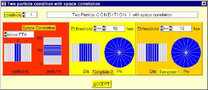
12 Condition to find 2 isolated electrons/photons with spatial correlation INPUT REGISTER for IEG1...4_(Et, phi, eta) LUT values for IEG templates: T1, T2, CORR_PHI, CORR_ETA <== Setup file IEG1_PHI IEG1_ETA IEG1_ET IEG1_PHI IEG2_PHI IEG1_ETA IEG2_ETA WCMP5 WCMP4 CMP6 SUB5 SUB4 AND T1 4+4=8 x T2 WCMP6 WCMP5 6 x 6 x intermediate REGISTER AND4_OR12 clock
13 Backplane 6U Prototype VME BUS SWITCH 5bit JTAG Bus 110F Addressable JTAG Port with JTAG Bridge Fairchild SCANPSC110F and Switch 1 loop / board L1 GLOBAL TRIGGER JTAG TESTS Cable from TAP Controller to Backplane JTAG Explorer PM3705/C Cable to Parallel Port JTAG TECHNOLOGY PF2171 Full Development Software
14 component JTAG CLUSTER Memory,.. JTAG component Memory cluster file.mcd FUNCTION Signal Definition file.sdf net name, col#, direction ad03 1 I ad02 2 I : : noe 9 I nwe 10 I Define in- and output signals of cluster Signal Level file.slf address data ctrl DDDD XXXX UU DDDD XXXX DU DDDD HLHL UU normal cluster test Define Function of cluster by test vectors Example: read CLUSTER TESTS
15 BSDL file.sel file data sheet files select components with BSC circuit net info file.nif file Altera, National, TexasInstr., Xilinx... nets locked on defined levels JTAG TEST VIP Manager INFRASTRUCTURE TEST INTERCONNECTION TEST EDIF netlist vl2jtag.net.pkg.wir package, wiring files ViewDraw PCB Schematic //..tests JTAG chain if all components connected //..tests nets between components containing a JTAG circuit.sdf.slf.mcd cluster definition files CLUSTER TEST //..tests nets between components containing a JTAG circuit and components without JTAG Technology SOFTWARE
16 Schedule 2001 GTL-prototype: VHDL design finished and prototype board produced delay Nov 2000 ==> Jan 2001 Software for Design and Tests until March FDL board: Functions defined and top-down design done until Nov FPGA chips designed and FDL board built until Nov GMT : Conceptual design until Nov 2000 define and simulate final algorithms JTAG software and tests: available until Dec 00...already working
17 Milestones 1999, D431 - June 1999 PSB_6U prototype production Status: Board tested. BACK6U design Status: done D432 Nov 1999 milestone changed BACK6U production Status: Board in use. D433 - June 2000 GTL_6U design Status: Delay due to redesign D434 Nov 2000 Trigger Logic Functions tested GTL_6U tested; Status: Delay FDL_9U design Combined logic test: Backplane + PSB + GTL Conceptual GlobalMuon Trigger design D435 - Nov 2001 Complete Logic Pipeline tested Combined Prototype test: Backplane + PSB + GTL+FDL D436 - June channel Global Trigger available D437- Nov 2003 Global Muon Trigger available D438 - Nov channel Global Trigger available
18 LATENCY
19 1/4-1/2 BC 81bx DPM GMT LATENCY min. MUON LATENCY 10 BC..without unit conversion 4DT-4bRPC 4CSC-4fRPC 91bx 160MHz GMT-IN PHASE FPGA Synchronisation MATCH LOGIC PAIR LOGIC MUON MERGER FINAL SORTER GT INPUT Register 4 DT,4 CSC, 8 RPC Muons SINGLE RANK TABLES GMT-LOGIC FPGA SorterFPGA MIP, ISO bits from GCT 75bx Chann Link LATENCY 8 BC PSB module Delay FIFO Ch Link 80MHz PROJ. TABLES Ch Link 83bx MIP, ISO bit ASSIGNMENT PROJECTION FPGA LATENCY 8 BC = combinatorial logic min. ISO/MIP bit LATENCY 16 BC 91bx
20 GT+GMT LATENCY 81 BX 91 BX 99 BX CSC, DT,RPC TRIGGER PARALLEL LINK GLOBAL MUON TRIGGER LATENCY 1 +9 BX SYNC LOGIC 9BX LOGIC + LUT Critical Path PARALLEL LINK Backplane GTL 1BX 1BX 1BX LATENCY 5 BX PARTICLE CONDITIONS 1BX 1BX AND-OR LOGIC CABLE PARALLEL LINK FDL LATENCY 3 BX FINAL OR- LOGIC PARALLEL LINK 85 BX PSB LATENCY 3 BX 88 BX 3 BX 128 ALGORITHMS Latency without Trigger Control System TCS. L1ACCEPT GCT PHASE SYNC PIPELINE DELAY CHANNEL LINK 80 MHz SYNCHRONISATION LOGIC Phase Sync: 1/4-3/4 BX CHANNEL LINK 80 MHz Muon input to L1Accept output: 18 BX Calo input to L1Accept output: 14 BX GCT data later than before ==>PIPELINE DELAY in PSB!!
21 Estimated FDL to TTCvx latency GT PROCESSOR BX=99 BX=100 XXX XXX XXX BX=104 FINAL OR- LOGIC 1 BX PARALLEL LINK Backplane 1 BX MUX TCS TTS Calibration 9 ns* 1 or 2 BX? PARALLEL LINK TP-CABLE <1.5m?7 ns*? TTCvi logic L1A A B 40MHz? MUX, O.L. Encoder 9U VME FDL 9U VME TCS 6U/4TE VME TTCvi 6U/4TE, PECL TTCvx *Driver: = 9 ns FPGA: clk2out 6 ns net on board: 1 ns fast LVDS driver 2ns *Receiver: =?7 ns fast LVDS receiver: 2ns net on board: 1 ns FPGA setup 3 ns 25-16=9ns ==> <1.5 m cable for 1bx transfer latency if CLK signals on TCS and TTCvi switch simultanously. CABLE < 1m DS90LV031A TP cable: 1.6 ns/ft=5.3 ns/m FDL to TTCvx latency
Trigger Report. Wesley H. Smith CMS Trigger Project Manager Report to Steering Committee February 23, 2004
 Trigger Report Wesley H. Smith CMS Trigger Project Manager Report to Steering Committee February 23, 2004 Outline: Calorimeter Triggers Muon Triggers Global Triggers The pdf file of this talk is available
Status of the CSC Track-Finder
 Status of the CSC Track-Finder D. Acosta, S.M. Wang University of Florida A.Atamanchook, V.Golovstov, B.Razmyslovich PNPI CSC Muon Trigger Scheme Strip FE cards Strip LCT card CSC Track-Finder LCT Motherboard
CMS Conference Report
 Available on CMS information server CMS CR 1997/017 CMS Conference Report 22 October 1997 Updated in 30 March 1998 Trigger synchronisation circuits in CMS J. Varela * 1, L. Berger 2, R. Nóbrega 3, A. Pierce
WBS Trigger. Wesley Smith, U. Wisconsin CMS Trigger Project Manager. DOE/NSF Review April 11, 2000
 WBS 3.1 - Trigger Wesley Smith, U. Wisconsin CMS Trigger Project Manager DOE/NSF Review April 11, 2000 US CMS DOE/NSF Review, April 11-13, 2000 1 Outline Overview of Calorimeter Trigger Calorimeter Trigger
Design of the Level-1 Global Calorimeter Trigger
 Design of the Level-1 Global Calorimeter Trigger For I reckon that the sufferings of this present time are not worthy to be compared with the glory which shall be revealed to us The epistle of Paul the
12 Cathode Strip Chamber Track-Finder
 CMS Trigger TDR DRAFT 12 Cathode Strip Chamber Track-Finder 12 Cathode Strip Chamber Track-Finder 12.1 Requirements 12.1.1 Physics Requirements The L1 trigger electronics of the CMS muon system must measure
Trigger Cost & Schedule
 Trigger Cost & Schedule Wesley Smith, U. Wisconsin CMS Trigger Project Manager DOE/NSF Review May 9, 2001 1 Baseline L4 Trigger Costs From April '00 Review -- 5.69 M 3.96 M 1.73 M 2 Calorimeter Trig. Costs
TTC Interface Module for ATLAS Read-Out Electronics: Final production version based on Xilinx FPGA devices
 Physics & Astronomy HEP Electronics TTC Interface Module for ATLAS Read-Out Electronics: Final production version based on Xilinx FPGA devices LECC 2004 Matthew Warren warren@hep.ucl.ac.uk Jon Butterworth,
Test Beam Wrap-Up. Darin Acosta
 Test Beam Wrap-Up Darin Acosta Agenda Darin/UF: General recap of runs taken, tests performed, Track-Finder issues Martin/UCLA: Summary of RAT and RPC tests, and experience with TMB2004 Stan(or Jason or
The TRIGGER/CLOCK/SYNC Distribution for TJNAF 12 GeV Upgrade Experiments
 1 1 1 1 1 1 1 1 0 1 0 The TRIGGER/CLOCK/SYNC Distribution for TJNAF 1 GeV Upgrade Experiments William GU, et al. DAQ group and Fast Electronics group Thomas Jefferson National Accelerator Facility (TJNAF),
US CMS Endcap Muon. Regional CSC Trigger System WBS 3.1.1
 WBS Dictionary/Basis of Estimate Documentation US CMS Endcap Muon Regional CSC Trigger System WBS 3.1.1-1- 1. INTRODUCTION 1.1 The CMS Muon Trigger System The CMS trigger and data acquisition system is
18 Nov 2015 Testing and Programming PCBA s. 1 JTAG Technologies
 8 Nov 25 Testing and Programming PCBA s JTAG Technologies The importance of Testing Don t ship bad products to your customers, find problems before they do. DOA s (Death On Arrival) lead to huge costs
WBS Calorimeter Trigger. Wesley Smith, U. Wisconsin CMS Trigger Project Manager. DOE/NSF Review April 12, 2000
 WBS 3.1.2 - Calorimeter Trigger Wesley Smith, U. Wisconsin CMS Trigger Project Manager DOE/NSF Review April 12, 2000 1 Calorimeter Electronics Interface Calorimeter Trigger Overview 4K 1.2 Gbaud serial
Description of the Synchronization and Link Board
 Available on CMS information server CMS IN 2005/007 March 8, 2005 Description of the Synchronization and Link Board ECAL and HCAL Interface to the Regional Calorimeter Trigger Version 3.0 (SLB-S) PMC short
ADF-2 Production Readiness Review
 ADF-2 Production Readiness Review Presented by D. Edmunds 11-FEB-2005 The ADF-2 circuit board is part of the new Run IIB Level 1 Calorimeter Trigger. The purpose of this note is to provide the ADF-2 Production
BABAR IFR TDC Board (ITB): system design
: system design") BABAR IFR TDC Board (ITB): system design Version 1.1 12 december 1997 G. Crosetti, S. Minutoli, E. Robutti I.N.F.N. Genova 1. Introduction TDC readout of the IFR will be used during BABAR data taking to
BABAR IFR TDC Board (ITB): system design Version 1.1 12 december 1997 G. Crosetti, S. Minutoli, E. Robutti I.N.F.N. Genova 1. Introduction TDC readout of the IFR will be used during BABAR data taking to
CMS Note Mailing address: CMS CERN, CH-1211 GENEVA 23, Switzerland
 Available on CMS information server CMS NOTE 2007/000 The Compact Muon Solenoid Experiment CMS Note Mailing address: CMS CERN, CH-1211 GENEVA 23, Switzerland DRAFT 23 Oct. 2007 The CMS Drift Tube Trigger
The CMS Drift Tube Trigger Track Finder
 Preprint typeset in JINST style - HYPER VERSION The CMS Drift Tube Trigger Track Finder J. Erö, Ch. Deldicque, M. Galánthay, H. Bergauer, M. Jeitler, K. Kastner, B. Neuherz, I. Mikulec, M. Padrta, H. Rohringer,
CSC Muon Trigger. Jay Hauser. Director s Review Fermilab, Apr 30, Outline
 CSC Muon Trigger Jay Hauser Director s Review Fermilab, Apr 30, 2002 Outline The CSC muon trigger design Project scope Fall 2000 prototype test Pre-production prototype to be tested Summer 03 Conclusions
DT Trigger Server: Milestone D324 : Sep99 TSM (ASIC) 1st prototype
 1st prototype") DT Trigger Server: Sorting Step 2: Track Sorter Master Milestone D324 : Sep99 TSM (ASIC) 1st prototype work of : M.D., I.Lax, C.Magro, A.Montanari, F.Odorici, G.Torromeo, R.Travaglini, M.Zuffa (INFN\Bologna)
DT Trigger Server: Sorting Step 2: Track Sorter Master Milestone D324 : Sep99 TSM (ASIC) 1st prototype work of : M.D., I.Lax, C.Magro, A.Montanari, F.Odorici, G.Torromeo, R.Travaglini, M.Zuffa (INFN\Bologna)
Local Trigger Electronics for the CMS Drift Tubes Muon Detector
 Amsterdam, 1 October 2003 Local Trigger Electronics for the CMS Drift Tubes Muon Detector Presented by R.Travaglini INFN-Bologna Italy CMS Drift Tubes Muon Detector CMS Barrel: 5 wheels Wheel : Azimuthal
SuperB- DCH. Servizio Ele<ronico Laboratori FrascaA
 1 Outline 2 DCH FEE Constraints/Estimate & Main Blocks front- end main blocks Constraints & EsAmate Trigger rate (150 khz) Trigger/DAQ data format I/O BW Trigger Latency Minimum trigger spacing. Chamber
Remote Diagnostics and Upgrades
 Remote Diagnostics and Upgrades Tim Pender -Eastman Kodak Company 10/03/03 About this Presentation Motivation for Remote Diagnostics Reduce Field Maintenance costs Product needed to support 100 JTAG chains
LHCb and its electronics. J. Christiansen On behalf of the LHCb collaboration
 LHCb and its electronics J. Christiansen On behalf of the LHCb collaboration Physics background CP violation necessary to explain matter dominance B hadron decays good candidate to study CP violation B
S.Cenk Yıldız on behalf of ATLAS Muon Collaboration. Topical Workshop on Electronics for Particle Physics, 28 September - 2 October 2015
 THE ATLAS CATHODE STRIP CHAMBERS A NEW ATLAS MUON CSC READOUT SYSTEM WITH SYSTEM ON CHIP TECHNOLOGY ON ATCA PLATFORM S.Cenk Yıldız on behalf of ATLAS Muon Collaboration University of California, Irvine
BABAR IFR TDC Board (ITB): requirements and system description
: requirements and system description") BABAR IFR TDC Board (ITB): requirements and system description Version 1.1 November 1997 G. Crosetti, S. Minutoli, E. Robutti I.N.F.N. Genova 1. Timing measurement with the IFR Accurate track reconstruction
BABAR IFR TDC Board (ITB): requirements and system description Version 1.1 November 1997 G. Crosetti, S. Minutoli, E. Robutti I.N.F.N. Genova 1. Timing measurement with the IFR Accurate track reconstruction
Optical Link Evaluation Board for the CSC Muon Trigger at CMS
 Optical Link Evaluation Board for the CSC Muon Trigger at CMS 04/04/2001 User s Manual Rice University, Houston, TX 77005 USA Abstract The main goal of the design was to evaluate a data link based on Texas
COE758 Xilinx ISE 9.2 Tutorial 2. Integrating ChipScope Pro into a project
 COE758 Xilinx ISE 9.2 Tutorial 2 ChipScope Overview Integrating ChipScope Pro into a project Conventional Signal Sampling Xilinx Spartan 3E FPGA JTAG 2 ChipScope Pro Signal Sampling Xilinx Spartan 3E FPGA
Achieving Timing Closure in ALTERA FPGAs
 Achieving Timing Closure in ALTERA FPGAs Course Description This course provides all necessary theoretical and practical know-how to write system timing constraints for variety designs in ALTERA FPGAs.
Programmable Logic Design I
 Programmable Logic Design I Introduction In labs 11 and 12 you built simple logic circuits on breadboards using TTL logic circuits on 7400 series chips. This process is simple and easy for small circuits.
FPGA Design. Part I - Hardware Components. Thomas Lenzi
 FPGA Design Part I - Hardware Components Thomas Lenzi Approach We believe that having knowledge of the hardware components that compose an FPGA allow for better firmware design. Being able to visualise
EECS150 - Digital Design Lecture 18 - Circuit Timing (2) In General...
 In General...") EECS150 - Digital Design Lecture 18 - Circuit Timing (2) March 17, 2010 John Wawrzynek Spring 2010 EECS150 - Lec18-timing(2) Page 1 In General... For correct operation: T τ clk Q + τ CL + τ setup for all
EECS150 - Digital Design Lecture 18 - Circuit Timing (2) March 17, 2010 John Wawrzynek Spring 2010 EECS150 - Lec18-timing(2) Page 1 In General... For correct operation: T τ clk Q + τ CL + τ setup for all
CMS Tracker Synchronization
 CMS Tracker Synchronization K. Gill CERN EP/CME B. Trocme, L. Mirabito Institut de Physique Nucleaire de Lyon Outline Timing issues in CMS Tracker Synchronization method Relative synchronization Synchronization
KEK. Belle2Link. Belle2Link 1. S. Nishida. S. Nishida (KEK) Nov.. 26, Aerogel RICH Readout
 Nov.. 26, Aerogel RICH Readout") S. Nishida KEK Nov 26, 2010 1 Introduction (Front end electronics) ASIC (SA) Readout (Digital Part) HAPD (144ch) Preamp Shaper Comparator L1 buffer DAQ group Total ~ 500 HAPDs. ASIC: 36ch per chip (i.e.
S. Nishida KEK Nov 26, 2010 1 Introduction (Front end electronics) ASIC (SA) Readout (Digital Part) HAPD (144ch) Preamp Shaper Comparator L1 buffer DAQ group Total ~ 500 HAPDs. ASIC: 36ch per chip (i.e.
16 Dec Testing and Programming PCBA s. 1 JTAG Technologies
 6 Dec 24 Testing and Programming PCBA s JTAG Technologies The importance of Testing Don t ship bad products to your customers, find problems before they do. DOA s (Death On Arrival) lead to huge costs
FPGA Development for Radar, Radio-Astronomy and Communications
 John-Philip Taylor Room 7.03, Department of Electrical Engineering, Menzies Building, University of Cape Town Cape Town, South Africa 7701 Tel: +27 82 354 6741 email: tyljoh010@myuct.ac.za Internet: http://www.uct.ac.za
Solutions to Embedded System Design Challenges Part II
 Solutions to Embedded System Design Challenges Part II Time-Saving Tips to Improve Productivity In Embedded System Design, Validation and Debug Hi, my name is Mike Juliana. Welcome to today s elearning.
Timing EECS141 EE141. EE141-Fall 2011 Digital Integrated Circuits. Pipelining. Administrative Stuff. Last Lecture. Latch-Based Clocking.
 EE141-Fall 2011 Digital Integrated Circuits Lecture 2 Clock, I/O Timing 1 4 Administrative Stuff Pipelining Project Phase 4 due on Monday, Nov. 21, 10am Homework 9 Due Thursday, December 1 Visit to Intel
Latest Timing System Developments
 Latest Timing System Developments Jukka Pietarinen EPICS Collaboration Meeting Shanghai March 2008 25.4.2007 Register Map Changes (new register mapping) CompactPCI boards implement new register mapping
FPGA Design with VHDL
 FPGA Design with VHDL Justus-Liebig-Universität Gießen, II. Physikalisches Institut Ming Liu Dr. Sören Lange Prof. Dr. Wolfgang Kühn ming.liu@physik.uni-giessen.de Lecture Digital design basics Basic logic
Level 1 Calorimeter Trigger:
 ATL DA ES 0038 30 November 2006 EDMS document number 489129 Version Draft 0.6 Level 1 Calorimeter Trigger: DAQ and CMM cabling L1Calo Group 1 1 Introduction The purpose of this note is to complete the
LHCb and its electronics.
 LHCb and its electronics. J. Christiansen, CERN On behalf of the LHCb collaboration jorgen.christiansen@cern.ch Abstract The general architecture of the electronics systems in the LHCb experiment is described
Field Programmable Gate Array (FPGA) Based Trigger System for the Klystron Department. Darius Gray
 Based Trigger System for the Klystron Department. Darius Gray") SLAC-TN-10-007 Field Programmable Gate Array (FPGA) Based Trigger System for the Klystron Department Darius Gray Office of Science, Science Undergraduate Laboratory Internship Program Texas A&M University,
SLAC-TN-10-007 Field Programmable Gate Array (FPGA) Based Trigger System for the Klystron Department Darius Gray Office of Science, Science Undergraduate Laboratory Internship Program Texas A&M University,
GREAT 32 channel peak sensing ADC module: User Manual
 GREAT 32 channel peak sensing ADC module: User Manual Specification: 32 independent timestamped peak sensing, ADC channels. Input range 0 to +8V. Sliding scale correction. Peaking time greater than 1uS.
AD9884A Evaluation Kit Documentation
 a (centimeters) AD9884A Evaluation Kit Documentation Includes Documentation for: - AD9884A Evaluation Board - SXGA Panel Driver Board Rev 0 1/4/2000 Evaluation Board Documentation For the AD9884A Purpose
Large Area, High Speed Photo-detectors Readout
 Large Area, High Speed Photo-detectors Readout Jean-Francois Genat + On behalf and with the help of Herve Grabas +, Samuel Meehan +, Eric Oberla +, Fukun Tang +, Gary Varner ++, and Henry Frisch + + University
Update on DAQ for 12 GeV Hall C
 Update on DAQ for 12 GeV Hall C Brad Sawatzky Hall C Winter User Group Meeting Jan 20, 2017 SHMS/HMS Trigger/Electronics H. Fenker 2 SHMS / HMS Triggers SCIN = 3/4 hodoscope planes CER = Cerenkov(s) STOF
DT9834 Series High-Performance Multifunction USB Data Acquisition Modules
 DT9834 Series High-Performance Multifunction USB Data Acquisition Modules DT9834 Series High Performance, Multifunction USB DAQ Key Features: Simultaneous subsystem operation on up to 32 analog input channels,
EEM Digital Systems II
 ANADOLU UNIVERSITY DEPARTMENT OF ELECTRICAL AND ELECTRONICS ENGINEERING EEM 334 - Digital Systems II LAB 3 FPGA HARDWARE IMPLEMENTATION Purpose In the first experiment, four bit adder design was prepared
Why FPGAs? FPGA Overview. Why FPGAs?
 Transistor-level Logic Circuits Positive Level-sensitive EECS150 - Digital Design Lecture 3 - Field Programmable Gate Arrays (FPGAs) January 28, 2003 John Wawrzynek Transistor Level clk clk clk Positive
EE178 Lecture Module 4. Eric Crabill SJSU / Xilinx Fall 2005
 EE178 Lecture Module 4 Eric Crabill SJSU / Xilinx Fall 2005 Lecture #9 Agenda Considerations for synchronizing signals. Clocks. Resets. Considerations for asynchronous inputs. Methods for crossing clock
T1 Deframer. LogiCORE Facts. Features. Applications. General Description. Core Specifics
 November 10, 2000 Xilinx Inc. 2100 Logic Drive San Jose, CA 95124 Phone: +1 408-559-7778 Fax: +1 408-559-7114 E-mail: support@xilinx.com URL: www.xilinx.com/ipcenter Features Supports T1-D4 and T1-ESF
CSC Data Rates, Formats and Calibration Methods
 CSC Data Rates, Formats and Calibration Methods D. Acosta University of Florida With most information collected from the The Ohio State University PRS March Milestones 1. Determination of calibration methods
V6118 EM MICROELECTRONIC - MARIN SA. 2, 4 and 8 Mutiplex LCD Driver
 EM MICROELECTRONIC - MARIN SA 2, 4 and 8 Mutiplex LCD Driver Description The is a universal low multiplex LCD driver. The version 2 drives two ways multiplex (two blackplanes) LCD, the version 4, four
Advanced Training Course on FPGA Design and VHDL for Hardware Simulation and Synthesis. 26 October - 20 November, 2009
 2065-28 Advanced Training Course on FPGA Design and VHDL for Hardware Simulation and Synthesis 26 October - 20 November, 2009 Starting to make an FPGA Project Alexander Kluge PH ESE FE Division CERN 385,
Level and edge-sensitive behaviour
 Level and edge-sensitive behaviour Asynchronous set/reset is level-sensitive Include set/reset in sensitivity list Put level-sensitive behaviour first: process (clock, reset) is begin if reset = '0' then
Interfacing the TLC5510 Analog-to-Digital Converter to the
 Application Brief SLAA070 - April 2000 Interfacing the TLC5510 Analog-to-Digital Converter to the TMS320C203 DSP Perry Miller Mixed Signal Products ABSTRACT This application report is a summary of the
Digilent Nexys-3 Cellular RAM Controller Reference Design Overview
 Digilent Nexys-3 Cellular RAM Controller Reference Design Overview General Overview This document describes a reference design of the Cellular RAM (or PSRAM Pseudo Static RAM) controller for the Digilent
THE DIAGNOSTICS BACK END SYSTEM BASED ON THE IN HOUSE DEVELOPED A DA AND A D O BOARDS
 THE DIAGNOSTICS BACK END SYSTEM BASED ON THE IN HOUSE DEVELOPED A DA AND A D O BOARDS A. O. Borga #, R. De Monte, M. Ferianis, L. Pavlovic, M. Predonzani, ELETTRA, Trieste, Italy Abstract Several diagnostic
XJTAG. Boundary Scan Tool. diagnosys.com
 XJTAG Boundary Scan Tool diagnosys.com XJLink Overview The XJLink is a small, portable, USB 2.0 to JTAG adapter that provides a high speed interface (480Mbps) to the JTAG chain. The small, lightweight
Ilmenau, 9 Dec 2016 Testing and programming PCBA s. 1 JTAG Technologies
 Ilmenau, 9 Dec 206 Testing and programming PCBA s JTAG Technologies The importance of Testing Don t ship bad products to your customers, find problems before they do. DOA s (Death On Arrival) lead to huge
PIXEL2000, June 5-8, FRANCO MEDDI CERN-ALICE / University of Rome & INFN, Italy. For the ALICE Collaboration
 PIXEL2000, June 5-8, 2000 FRANCO MEDDI CERN-ALICE / University of Rome & INFN, Italy For the ALICE Collaboration CONTENTS: Introduction: Physics Requirements Design Considerations Present development status
System-Level Timing Closure Using IBIS Models
 System-Level Timing Closure Using IBIS Models Barry Katz President/CTO, SiSoft Asian IBIS Summit Asian IBIS Summit Tokyo, Japan - October 31, 2006 Signal Integrity Software, Inc. Agenda High Speed System
A Briefing on IEEE Standard Test Access Port And Boundary-Scan Architecture ( AKA JTAG )
") A Briefing on IEEE 1149.1 1990 Standard Test Access Port And Boundary-Scan Architecture ( AKA JTAG ) Summary With the advent of large Ball Grid Array (BGA) and fine pitch SMD semiconductor devices the
A Briefing on IEEE 1149.1 1990 Standard Test Access Port And Boundary-Scan Architecture ( AKA JTAG ) Summary With the advent of large Ball Grid Array (BGA) and fine pitch SMD semiconductor devices the
Design, Realization and Test of a DAQ chain for ALICE ITS Experiment. S. Antinori, D. Falchieri, A. Gabrielli, E. Gandolfi
 Design, Realization and Test of a DAQ chain for ALICE ITS Experiment S. Antinori, D. Falchieri, A. Gabrielli, E. Gandolfi Physics Department, Bologna University, Viale Berti Pichat 6/2 40127 Bologna, Italy
Update on DAQ for 12 GeV Hall C. Brad Sawatzky
 Update on DAQ for 12 GeV Hall C Brad Sawatzky SHMS/HMS Trigger/Electronics H. Fenker 2 SHMS / HMS Triggers SCIN = 3/4 hodoscope planes CER = Cerenkov(s) STOF = S1 + S2 EL-Hi = SCIN + PSh_Hi EL-Lo = 2/3{SCIN,
SignalTap Plus System Analyzer
 SignalTap Plus System Analyzer June 2000, ver. 1 Data Sheet Features Simultaneous internal programmable logic device (PLD) and external (board-level) logic analysis 32-channel external logic analyzer 166
A video signal processor for motioncompensated field-rate upconversion in consumer television
 A video signal processor for motioncompensated field-rate upconversion in consumer television B. De Loore, P. Lippens, P. Eeckhout, H. Huijgen, A. Löning, B. McSweeney, M. Verstraelen, B. Pham, G. de Haan,
Electronics Status and Upgrade Opportunities for Flash ADC and 12GeV Trigger Hardware
 Electronics Status and Upgrade Opportunities for Flash ADC and 12GeV Trigger Hardware R. Chris Cuevas Group Leader Fast Electronics NPS Collaboration Meeting Jefferson Lab 14-November-2013 Page 1 OUTLINE
TTC laser transmitter (TTCex, TTCtx, TTCmx) User Manual
 User Manual") B.G. Taylor RD12 working document Rev 2.0 TTC laser transmitter (TTCex, TTCtx, TTCmx) User Manual Three types of laser transmitter module have been developed by RD12 for TTC signal distribution at the
B.G. Taylor RD12 working document Rev 2.0 TTC laser transmitter (TTCex, TTCtx, TTCmx) User Manual Three types of laser transmitter module have been developed by RD12 for TTC signal distribution at the
Trigger synchronization and phase coherent in high speed multi-channels data acquisition system
 White Paper Trigger synchronization and phase coherent in high speed multi-channels data acquisition system Synopsis Trigger synchronization and phase coherent acquisition over multiple Data Acquisition
AI-1204Z-PCI. Features. 10MSPS, 12-bit Analog Input Board for PCI AI-1204Z-PCI 1. Ver.1.04
 10MSPS, 12-bit Analog Board for PCI AI-1204Z-PCI * Specifications, color and design of the products are subject to change without notice. This product is a PCI bus-compliant interface board that expands
ALICE Muon Trigger upgrade
 ALICE Muon Trigger upgrade Context RPC Detector Status Front-End Electronics Upgrade Readout Electronics Upgrade Conclusions and Perspectives Dr Pascal Dupieux, LPC Clermont, QGPF 2013 1 Context The Muon
of Boundary Scan techniques.
 SMT TEHNOLOGY Boundary Scan Techniques for Test Coverage Improvement When discussing the JTAG protocol, most engineers immediately think of In System Programming procedures. Indeed, there are numerous
SPS BPM system renovation. Roadmap & Milestones
 SPS BPM system renovation Roadmap & Milestones Synopsis Introduction and Overview: Andrea Infrastructures Fibres: Simao Cables: Joel Electronics Analogue Front-End: Manfred Digital Front-End: Manoel Back-End:
The ATLAS Level-1 Central Trigger
 he AAS evel-1 entral rigger RSpiwoks a, SAsk b, DBerge a, Daracinha a,c, NEllis a, PFarthouat a, PGallno a, SHaas a, PKlofver a, AKrasznahorkay a,d, AMessina a, Ohm a, Pauly a, MPerantoni e, HPessoa ima
Muon Trigger Flavor Board (MTFB) Design and Specifications
 Design and Specifications") Muon Trigger Flavor Board (MTFB) Design and Specifications Issue 2.41 December 11, 1998 Prepared by: Ken Johns, Freedy Nang, Kevin Davis, Rob McCroskey, and David Fein University of Arizona Tucson, Arizona
Muon Trigger Flavor Board (MTFB) Design and Specifications Issue 2.41 December 11, 1998 Prepared by: Ken Johns, Freedy Nang, Kevin Davis, Rob McCroskey, and David Fein University of Arizona Tucson, Arizona
Zebra2 (PandA) Functionality and Development. Isa Uzun and Tom Cobb
 Functionality and Development. Isa Uzun and Tom Cobb") Zebra2 (PandA) Functionality and Development Isa Uzun and Tom Cobb Control Systems Group 27 April 2016 Outline Part - I ZEBRA and Motivation Hardware Architecture Functional Capabilities Part - II Software
Zebra2 (PandA) Functionality and Development Isa Uzun and Tom Cobb Control Systems Group 27 April 2016 Outline Part - I ZEBRA and Motivation Hardware Architecture Functional Capabilities Part - II Software
7 Nov 2017 Testing and programming PCBA s
 7 Nov 207 Testing and programming PCBA s Rob Staals JTAG Technologies Email: robstaals@jtag.com JTAG Technologies The importance of Testing Don t ship bad products to your customers, find problems before
Racks, Cabling and Latency
 Racks, Cabling and Latency Murrough Landon 2 November 2000 Overview Rack Layout Cabling paths Latency estimates Outstanding issues "! #%$"! & % &(' Racks Layout Original Requirements Minimise the overall
IE1204 Digital Design F11: Programmable Logic, VHDL for Sequential Circuits
 IE1204 Digital Design F11: Programmable Logic, VHDL for Sequential Circuits Elena Dubrova KTH/ICT/ES dubrova@kth.se This lecture BV pp. 98-118, 418-426, 507-519 IE1204 Digital Design, HT14 2 Programmable
Laboratory Exercise 4
 Laboratory Exercise 4 Polling and Interrupts The purpose of this exercise is to learn how to send and receive data to/from I/O devices. There are two methods used to indicate whether or not data can be
JESD204B IP Hardware Checkout Report with AD9250. Revision 0.5
 JESD204B IP Hardware Checkout Report with AD9250 Revision 0.5 November 13, 2013 Table of Contents Revision History... 2 References... 2 1 Introduction... 3 2 Scope... 3 3 Result Key... 3 4 Hardware Setup...
Memory Interfaces Data Capture Using Direct Clocking Technique Author: Maria George
 Application Note: Virtex-4 Family R XAPP701 (v1.4) October 2, 2006 Memory Interfaces Data Capture Using Direct Clocking Technique Author: Maria George Summary This application note describes the direct-clocking
EN2911X: Reconfigurable Computing Topic 01: Programmable Logic. Prof. Sherief Reda School of Engineering, Brown University Fall 2014
 EN2911X: Reconfigurable Computing Topic 01: Programmable Logic Prof. Sherief Reda School of Engineering, Brown University Fall 2014 1 Contents 1. Architecture of modern FPGAs Programmable interconnect
Digital Blocks Semiconductor IP
 Digital Blocks Semiconductor IP DB1825 Color Space Converter & Chroma Resampler General Description The Digital Blocks DB1825 Color Space Converter & Chroma Resampler Verilog IP Core transforms 4:4:4 sampled
3. Configuration and Testing
 3. Configuration and Testing C51003-1.4 IEEE Std. 1149.1 (JTAG) Boundary Scan Support All Cyclone devices provide JTAG BST circuitry that complies with the IEEE Std. 1149.1a-1990 specification. JTAG boundary-scan
IE1204 Digital Design. F11: Programmable Logic, VHDL for Sequential Circuits. Masoumeh (Azin) Ebrahimi
 Ebrahimi") IE1204 Digital Design F11: Programmable Logic, VHDL for Sequential Circuits Masoumeh (Azin) Ebrahimi (masebr@kth.se) Elena Dubrova (dubrova@kth.se) KTH / ICT / ES This lecture BV pp. 98-118, 418-426, 507-519
IE1204 Digital Design F11: Programmable Logic, VHDL for Sequential Circuits Masoumeh (Azin) Ebrahimi (masebr@kth.se) Elena Dubrova (dubrova@kth.se) KTH / ICT / ES This lecture BV pp. 98-118, 418-426, 507-519
Certus TM Silicon Debug: Don t Prototype Without It by Doug Amos, Mentor Graphics
 Certus TM Silicon Debug: Don t Prototype Without It by Doug Amos, Mentor Graphics FPGA PROTOTYPE RUNNING NOW WHAT? Well done team; we ve managed to get 100 s of millions of gates of FPGA-hostile RTL running
FRONT-END AND READ-OUT ELECTRONICS FOR THE NUMEN FPD
 FRONT-END AND READ-OUT ELECTRONICS FOR THE NUMEN FPD D. LO PRESTI D. BONANNO, F. LONGHITANO, D. BONGIOVANNI, S. REITO INFN- SEZIONE DI CATANIA D. Lo Presti, NUMEN2015 LNS, 1-2 December 2015 1 OVERVIEW
Digital Blocks Semiconductor IP
 Digital Blocks Semiconductor IP General Description The Digital Blocks IP Core decodes an ITU-R BT.656 digital video uncompressed NTSC 720x486 (525/60 Video System) and PAL 720x576 (625/50 Video System)
A new Interlock Design for the TESLA RF System
 A new Interlock Design for the TESLA RF System H. Leich 1, A. Kretzschmann 1, S. Choroba 2, T. Grevsmühl 2, N. Heidbrook 2, J. Kahl 2, 1 (DESY Zeuthen) 2 (DESY Hamburg) The Problem The Interlock Architecture
PICOSECOND TIMING USING FAST ANALOG SAMPLING
 PICOSECOND TIMING USING FAST ANALOG SAMPLING H. Frisch, J-F Genat, F. Tang, EFI Chicago, Tuesday 6 th Nov 2007 INTRODUCTION In the context of picosecond timing, analog detector pulse sampling in the 10
VARIABLE FREQUENCY CLOCKING HARDWARE
 VARIABLE FREQUENCY CLOCKING HARDWARE Variable-Frequency Clocking Hardware Many complex digital systems have components clocked at different frequencies Reason 1: to reduce power dissipation The active
TKK S ASIC-PIIRIEN SUUNNITTELU
 Design TKK S-88.134 ASIC-PIIRIEN SUUNNITTELU Design Flow 3.2.2005 RTL Design 10.2.2005 Implementation 7.4.2005 Contents 1. Terminology 2. RTL to Parts flow 3. Logic synthesis 4. Static Timing Analysis
An FPGA based Topological Processor Prototype for the ATLAS Level-1 Trigger Upgrade
 Preprint typeset in JINST style - HYPER VERSION An FPGA based Topological Processor Prototype for the ATLAS Level-1 Trigger Upgrade Bruno Bauss, Volker Büscher, Reinhold Degele, Weina Ji, Sebastian Moritz,
EE178 Spring 2018 Lecture Module 5. Eric Crabill
 EE178 Spring 2018 Lecture Module 5 Eric Crabill Goals Considerations for synchronizing signals Clocks Resets Considerations for asynchronous inputs Methods for crossing clock domains Clocks The academic
CDA 4253 FPGA System Design FPGA Architectures. Hao Zheng Dept of Comp Sci & Eng U of South Florida
 CDA 4253 FPGA System Design FPGA Architectures Hao Zheng Dept of Comp Sci & Eng U of South Florida FPGAs Generic Architecture Also include common fixed logic blocks for higher performance: On-chip mem.
Design and Implementation of an AHB VGA Peripheral
 Design and Implementation of an AHB VGA Peripheral 1 Module Overview Learn about VGA interface; Design and implement an AHB VGA peripheral; Program the peripheral using assembly; Lab Demonstration. System
FPGA Laboratory Assignment 4. Due Date: 06/11/2012
 FPGA Laboratory Assignment 4 Due Date: 06/11/2012 Aim The purpose of this lab is to help you understanding the fundamentals of designing and testing memory-based processing systems. In this lab, you will