VFR 1 Recorder USER MANUAL
|
|
|
- Lizbeth Higgins
- 6 years ago
- Views:
Transcription
1 Instrumentation and Engineering Services, Inc. VFR 1 Recorder USER MANUAL ies@iesrecorders.com IES, Inc. Tel: Navarre Parkway Suite 42 Fax: Tel Navarre FL Mary Esther Blvd., Suite 311 Fax Mary Esther, FL 32569
2 VFR Overview... 1 Specifications... 1 Electrical... 1 Power... 2 Physical... 2 Operational Theory... 2 Control Logic... 2 Analog-to-Digital (A/D) Converter... 3 Memory... 3 Micro-controller... 3 Oscillator Speed... 4 Amplifier Gains... 4 Amplifier Bias... 4 Triggering Modes... 4 Recorder Operational Modes... 5 Sleeping... 5 Standby... 5 Recording... 5 Awaiting T Data Downloading... 5 Interface Signals Location and Description... 5 Operational Software... 9 VFR Software Program Main Menu... 9 Page 1 of the Main Menu... 9 Page 2 of the Main Menu Page 3 of the Main Menu VFR Software Program Display Data Encapsulation Epoxy-Casting Compound Formulation Mold Preparation Container Preparation Compound Preparation Compound De-aeration Compound Application Compound Cure Recorder Packaging Epoxy Encapsulation Glass Bead Encapsulation Paraffin Encapsulation Appendix A Example VFR Settings Appendix B VFR 1 Signal Locations... 56
3 VFR 1 Overview The VFR1 is a reusable, compact, high shock, solid-state, recorder designed to acquire data in hostile test environments. The epoxy-encapsulated unit was designed to fit inside of a general-purpose bomb fuze booster cup. By installing the recorder in the place of the fuze booster and lead, the user is able to record the impact acceleration event as well as several analog and eight digital events. The VFR1 can be programmed for various trigger modes, filter frequencies, sample rates, amplifier gain, and amplifier bias. All of the programmable features are available to the user through a menu-driven computer operating system (operating in a Windows environment). On-line computer aided assistance is available to the user when setting-up the amplifier gain and bias. The user has a visual display of the recorder range and zero settings rather than relying on calculations. Low power consumption allows the test instrumentation to be built weeks before the test and extends the time for data retrieval. After a test, the recorder data is retrieved using a personal computer and the same computer operating system that is used to program the recorder. Specifications Electrical Number of Programmable Analog Channels...1 Number of Buffered Analog Channels...2 Number of Digital Channels...8 Analog Channel Sample Rate (High Speed) khz Analog Channel Sample Rate (Low Speed 0) khz Analog Channel Sample Rate (Low Speed 1) khz Analog Channel Sample Rate (Low Speed 2) khz Analog Channel Sample Rate (Low Speed 3) Hz Analog Channel Sample Rate (Low Speed 4) Hz Analog Channel Sample Rate (Low Speed 5)...28 Hz Analog Channel Sample Rate (Low Speed 6)...7 Hz Analog Channel Sample Rate (Low Speed 7) Hz Analog Channel Signal Bandwidth... Selectable 2.3kHz or 9.3kHz Analog Channel Amplitude Resolution digital steps Analog Channel (Programmable)... Filter8-pole elliptic low-pass Total Storage Capacity...524,288 data words (512K x 8) External Trigger 1 Signal to 10.0-volt pulse External Trigger 2 Signal to 3.3-volt pulse External Trigger 2 Input Impedance...10,000 ohms Internal Trigger...Slope Programmable Internal Trigger... Level Programmable 1
4 Power Supply Voltage...6 to 15 volts Standby Current micro amps (typical) Operating Current...10 milliamps (typical) Data Retention Current micro amps (typical) Sensor Reference Voltage volts Sensor Supply Current (Per Channel)...20 milliamps (maximum) Physical Shock Survivability...100,000 g Temperature Range...32oF to 160 o F Temperature Range (With Screening) oF to 160 o F Encapsulation... Epoxy Size (VFR #1)...See Figure 1 Below Figure 1. VFR 1 Size Operational Theory Figure 2 shows a simplified block diagram of the VFR1. The major components of the recorder are the control logic, the memory, the analog-to-digital (A/D) converter, and the micro-controller. Following is a description of each functional block. Control Logic The control logic provides the control logic that enables data collection when the recorder is triggered, places the recorder in a data retention mode when the incoming data has filled the memory, and enables an external computer to interrogate the memory to extract the data. The control logic also provides correct timing for writing the data into memory and sequentially addresses all available memory locations. 2
5 Figure 2. Block Diagram of VFR 1 Analog-to-Digital (A/D) Converter The recorder utilizes a CMOS 8-bit A/D converter for digitizing data. The control logic selects the sampling rate. The A/D contains a multiplexer that is controlled by the control logic. The multiplexer sequentially switches the A/D input through all of the available channels, samples the channel output, digitizes the sampled level, and then places the 8- bit digital word on the data bus for transfer to memory. Memory The data storage device used is a CMOS low-power static, random access memory. The recorder storage capacity is 524,288 data words (512K x 8 bits). Each sample digitized by the A/D is an eight-bit word and is stored as a data word in the memory. The A/D sequentially samples each analog channel, generating a data word for each and writing it in memory. Once all of the analog channels have been sampled, an addition eight-bit data word is written in memory. This data word contains the information from the eight digital channels. Micro-controller The micro-controller is the brain that enables the recorder flexibility. The laboratory computer communicates with the recorder through the micro-controller. The microcontroller accepts recorder configuration data from the laboratory computer through an RS-232 serial link. The configuration data contains instructions for oscillator speed, amplifier gains, amplifier bias, and triggering modes. 3
6 Oscillator Speed The oscillator speed controls the recorder sample rate. The VFR1 has one high speed and eight low speed options for the oscillator. The low speed is programmable and can be changed between tests. Table 3-1 lists all of the available sample rates, the sample periods, and the recording time available at that rate. SAMPLE RATE SAMPLE PERIOD RECORDING TIME 57.8 khz.017 mseconds Seconds 28.9 khz.035 mseconds Seconds 7.2 khz.138 mseconds Seconds 1.8 khz.553 mseconds Seconds 450 Hz mseconds Minutes 112 Hz mseconds Minutes 28 Hz mseconds Minutes 7 Hz mseconds Hours Table 1. Oscillator Sample Rates and Recording Times Amplifier Gains The amplifier gain sets the full-scale level of the data window. It is similar to setting the volts/division on a laboratory oscilloscope. The gain adjustment allows the user to reconfigure the recorder for different test requirements and different sensors. Unlike other commercially available recorders requiring gain calculations using complex formulas followed by gain settings through the installation of a calculated resistor value, the VFR1 is programmable using a laboratory computer. Amplifier Bias The amplifier bias adjustment is similar to adjusting the vertical position control of a laboratory oscilloscope. The bias adjustment allows the user to select the zero location of the data amplitude. The bias adjustment allows the user to reconfigure the recorder for different test requirements and different sensors. Triggering Modes The user is able to program the recorder, for either the standard G-switch triggering and/or an auto-triggering mode. In the auto-trigger mode, the micro controller monitors the recorder channel zero output and generate a trigger 2 signal when the signal crosses a bit threshold. The bit level selection for triggering the recorder when in the auto-trigger mode is programmable by the user so the level can be changed between tests or it can be disabled. The auto-trigger allows the recorder to be triggered in the same manner that a laboratory oscilloscope is triggered. If a G-switch is attached to the normal trigger pads, 4
7 the recorder is triggered by the first signal generated, either the G-switch or the auto- be disabled; it must be removed to prevent it from trigger. The G-switch cannot triggering the recorder. Recorder Operational Modes Sleeping Sleeping indicates the recorder is in the low current mode. It draws ma while the serial link is connected. When the serial is disconnected, the recorder draws under 500 ua and is dormant. The recorder can be programmed, and data downloaded while the serial link is connected, but the analog section remains off. Standby Standby indicates the analog section of the recorder is powered, but data is not being stored into memory. This mode is useful for measuring the data collection current of the recorder because the sensors are powered in this mode. Also, the analog outputs are active, so signals can be connected to the recorder to test/calibrate the analog section. Recording Recording data indicates the analog section is on and the recorder is actually storing data into memory. When the memory is full, the recorder will automatically turn itself off and go into the Sleep mode to conserve power. If the recorder is recovered after a test, and it is still in the Recording data mode (memory was not filled up), the Stop button must be pressed before the data can be downloaded. Awaiting T1 Awaiting External T1 indicates the recorder is in the Sleep mode, waiting for the correct external 3.3-volt pulse on the T1 pin of the recorder to wake it. The external pulse is ignored when the serial link is on. When T1 occurs, the recorder will automatically go into the Recording mode, sampling at the slow sampling rate. Note: If there is a sensor error, the recorder will be shut down into the Standby mode. So it is recommended that the recorder be put into the Recording data mode on the bench, before the test, to verify proper operation. After the recorder status indicates it is Awaiting External T1, the serial connection can be removed. Data Downloading Data transfer for the VFR recorder is accomplished using the same menu-driven computer operating system that is used to program the recorder. The software is a user friendly, menu driven program that allows the user to retrieve, display, and store data records. In addition, the software enables the user to magnify portions of the data record and with a cross hair, obtain timing and amplitude information and print the display. Interface Signals Location and Description Figure 3 illustrates all of the VFR1 signal locations. Following is a description of each input/output signal. 5
8 DIG 0 to DIG 7 Digital channel inputs with CMOS inputs impedance. Do not apply a voltage greater than Vcc or less than 0 volts to these inputs. CH 0 + Non-inverting input to the channel 0 differential amplifier. This signal is connected directly to the non-inverting input of an operational amplifier. Do not apply a voltage greater than Vref or less than 0 volts to this input. CH 0 Inverting input to the channel 0 differential amplifier. This signal is connected directly to the inverting input of an operational amplifier. Do not apply a voltage greater than Vref or less than 0 volts to this input. Figure 3. VFR 1 Input / Output Signal Location CH 1 IN Non-inverting input to the channel 1 operational amplifier. This signal is connected directly to the non-inverting input of an operational amplifier. Do not apply a voltage greater than Vref or less than 0 volts to this input. 6
9 CH 2 IN Non-inverting input to the channel 2 operational amplifier. This signal is connected directly to the non-inverting input of an operational amplifier. Do not apply a voltage greater than Vref or less than 0 volts to this input. CH 0 OUT CH O OUT is the recorder channel 0 amplifier output. This signal is also the input for the analog multiplexer. Use only high impedance instruments to measure this signal. OSC OUT OSC OUT is the output signal of the internal recorder oscillator. The frequency of the oscillator out signal is the sampling rate of each channel. This output is not active when the recorder in a sleep mode. Vcc Vcc is the regulated power supply output. This output will source 10 milliamps for an external load. Vref Vref is the regulated power supply for powering sensors. This power supply is only active while the recorder is acquiring data. This output will source 30 milliamps. GND GND is the power and signal ground. SW GND This signal is a switched ground. When the recorder is collecting data, the SW GND is at ground potential. When the recorder is in the sleep mode, the SW GND is at Vcc level. This single can only source/sink 1 milliamp. BATT BATT is a connection for an external battery. This input is not diode-coupled to any of the other battery connections and should not be used in conjunction with any other battery. This connection is intended to power the recorder when only one battery is used. Use of this connection for powering the recorder eliminates the diode voltage drop that the other battery connections have. BATT 1 BATT 1 is a connection for an external battery. This input is diode-coupled to Battery 2 and External Power Input. BATT 2 BATT 2 is a connection for an external battery. This input is diode-coupled to Battery 1 and External Power Input. 7
10 EXTERNAL POWER INPUT EXTERNAL POWER INPUT is a connection for an external battery. This input is diode-coupled to Battery 1 and Battery 2 inputs. This input is used by the interface box for application of external power during the recorder programming and data retrieval. TRIG 1 TRIG 1 is a latched input signal that provides a method of initiating the recorder data collection operation. This trigger signal is a positive pulse that can be between the voltage range of 3.0 to 10-volts. TRIG 2 TRIG 2 is a latched input signal that provides a method of initiating the recorder highspeed data collection operation. This is a CMOS input with a 10K ohm pull-down resistor. Do not apply input signals greater than 3.3-volts to this input. RS232-TX RS232-TX is an RS232 level signal used for communications between the recorder and the laboratory computer. 8

11 Operational Software The operational software was written as a menu-driven computer operating system utilizing the LabView programming language. This chapter is intended as a user manual for the operating system. A graphics approach has been taken to describe the operating system. Below is a display of each of the screen menu followed by a description of each item on that menu. VFR Software Program Main Menu Page 1 of the Main Menu. This is the opening menu of the VFR program. It shows the current status of the recorder, allows the control of the recorder, and download and display of the data. 9


12 Displays the Serial Number and the current operating status of the recorder. Displays the program version and copyright credits, shown below. Allows the selection of the serial port for communicating with the recorder. The choices are COM1, COM2, COM3, and COM4. If the proper port has been selected, and communication has been established, the LINK OK will turn on and the Polling indicator will flash on and off. 10

13 The recorder cannot be found. No serial link can be established. Possible causes are no power to the recorder, a bad cable connection, or the wrong serial com port is selected. Allows selection of different baud rates. Note: This is the default value and should not be changed. Occasionally, when first connecting the recorder to the serial port, a SERIAL ERROR can occur. A beep will be heard. This is OK, unless the recorder continues to have error problems. It could indicate more serious problems, such as loss of serial link or a problem with the recorder. Other errors can occur under Error Status. If this occurs, there is a serious problem with the recorder. If a Sensor Error occurs, it means the Channel Auto Bias at Start was enabled for the channels displayed, and the recorder was unable to set the Sensor bias when the START button was pressed. The recorder will not start recording data until the problem is corrected. Possible solutions are disabling the Channel Auto Bias at Start for that channel, balancing the sensor, or reducing the gain for that channel. This error could also indicate a bad sensor or sensor wire. 11

14 This is the main section for controlling the recorder. Clears any Error Status or Sensor Error Status warnings and silences the beeping. If the errors are not cleared with this button, there is a more serious problem with the recorder. These indicators flash to remind the User to READ SETUP on page 2 of the Main program, and READ CHANNEL DATA on page 3 of the Main program. This is VERY important to do as soon as serial link has been established with the recorder. This allows the User to verify the current settings programmed into the recorder s EEPROM. These will usually flash when the recorder is first connected to the serial port. Note: Data can still be downloaded even if the READ CHANNEL DATA or READ SETUP indicators are flashing. Sleeping indicates the recorder in the low current mode. It will draw ma while the serial link is connected. When the serial is disconnected, the recorder will draw under 500 ua and will be dormant. The recorder can be programmed, and data downloaded while the serial link is connected, but the analog section will remain off. 12
15 STOP will put the recorder into the SLEEP mode if it is currently RECORDING data, in STANDBY, or AWAITING T1. If the recorder is already in the SLEEP mode, nothing will happen. NOTE: If the recorder is currently RECORDING data, the STOP button MUST be pressed before any data can be downloaded. Standby indicates the analog section of the recorder is powered, but data IS NOT being stored into memory. This mode is useful for measuring the data collection current of the recorder, because the sensors are powered in this mode. Also, the analog outputs are active, so signals can be connected to the recorder to test/calibrate the analog section. Pressing this button will put the reocrder into the Standby mode. If the recorder is in the Recording data mode, this button is ignored. When in the Standby or Recording modes, these indicators display the analog outputs (0-255 bits) of the amplified analog channels. In the Standby mode, these values will float towards zero. Recording data indicates the analog section is on and the recorder is actually storing data into memory. When the memory is full, the recorder will automatically turn itself off and go into the Sleep mode to conserve power. If the recorder is recovered after a test, and it is still in the Recording data mode (memory was not filled up), the Stop button must be pressed before the data can be downloaded. 13
 will prompt the User to be sure they are ready to start recording data. Pressing Stop will turn off the data recording.")
16 The Start button must be pressed to start recording data. Data will start at the beginning of the memory and sample at the slow sampling rate and ALL previous data will be erased. A message (shown below) will prompt the User to be sure they are ready to start recording data. Pressing Stop will turn off the data recording. After the recorder is in the Recording Data mode, the serial connection can be removed. Note: If there is a Sensor Error, the recorder will put itself into the Standby mode, an error will sound, and no data will be recorded. You will need to correct the sensor problem before recording data. Awaiting External T1 indicates the recorder is in the Sleep mode, waiting for the correct external 3.3-volt pulse on the T1 pin of the recorder to wake it. The external pulse is ignored when the serial link is on. When T1 occurs, the recorder will automatically go into the Recording mode, sampling at the slow sampling rate. Note: If there is a sensor error, the recorder will be shut down into the Standby mode. So it is recommended that the recorder be put into the Recording data mode on the bench, before the test, to verify proper operation. After the recorder status indicates it is Awaiting External T1, the serial connection can be removed. INFO: The recorder will start recording data when the START button is pressed in the lab. This will work in most test applications, 14
17 because the recorder is collecting data at a low speed until an external T2 occurs, or the auto trigger is activated. But certain tests require low current and the recorder may remain dormant for long periods of time, such as, a sled track test. This requires the recorder to be in the SLEEP mode until woken by an external 3.3-volt signal, T1. The width of the T1 pulse required to wake the recorder can be selected on Page 2. The T1 Start button will put the recorder into the Awaiting External T1 mode. Pressing the Stop button will turn this off and put the recorder back into the Sleep mode. Displays the current battery voltage. A good way to determine the strength of the battery is to apply a load to it. Pressing the Battery Test button can do this. This turns on the analog section the recorder and which loads down the battery. The LOW BATT indicator blinks when the battery voltage is below 5.0 volts. It is highly recommended that a new battery be used if this occurs. The recorder monitors the battery voltage during a test and if it falls below a safe limit, the recorder is put into high speed and is shut down to conserve battery voltage. Note: If the battery voltage falls below ~5 volts while the recorder is collecting data, the recorder will automatically put itself into High Speed until the memory is full, and shut itself down to save battery energy and prevent data loss. The current recorder temperature is displayed while the serial link is connected. Also, the maximum temperature the recorder has seen in its lifetime is displayed. The display can be either in F or C. 15
18 After a test has been completed, the highest and lowest temperature during that test is displayed. These values are reset when the Start button is pressed and the serial link is disconnected. After a test has been completed, the starting and ending battery voltages are displayed. The recorder starts monitoring the voltage only after the serial link is disconnected. The voltage is monitored about once a minute. The current memory size. This can be selected for 512K or 32K data points. The memory size dedicated for each channel. The value is determined by the mode (number of analog channels activated) and the memory size selected (32K or 512K data points). The Channel mode is either 0 or 1 for the VFR2 recorder. Mode 0 has 3 programmable analog channels, only. Mode 1 has 3 programmable analog channels, and 4 buffered analog channels. The VFR2 recorder has only Mode 0, which is 1 programmable analog channel, and 2 buffered analog channels. Displays the current high speed and low speed settings, which are programmed, into the recorder. 16

19 Controls the downloading of the data after the test. If the recorder is still in the Recording Data mode, the STOP button must be pressed first, to stop the data collection. This will put the recorder into High speed until the memory is full. Note: The data will remain valid in memory until either power is removed from the recorder, or the START button is pressed. Also, data can still be downloaded even if the READ CHANNEL DATA or READ SETUP indicators are flashing, and do not need to be read before downloading the data. Downloads ALL the data in the recorder. Either 32K or 512K data points, depending on how the recorder was programmed. When downloading, this operation can be canceled. If there is a problem while downloading, such as, a parity error, the User will be warned, and the data can be downloaded again. Sometimes when data from a test is written into memory, not all the memory is used. In that case, the recorder indicates the Valid Memory Size. By pressing the Quick Download button, only the memory, which was used during the test, is downloaded. This reduces the time required for downloading. If there are any uncertainties, the User can simply download ALL the data by pressing the Download ALL Data button. 17


20 This screen pops up when downloading data. The User can stop the downloading process by pressing the ABORT DOWNLOADING button. It is Normal for the memory counter to go slightly past the memory size and stop for a short period of time. This message is displayed when ALL the data has been successfully downloaded from the recorder s memory. The data can be downloaded as many times as the Users wants, but it will be erased if power is removed from the recorder, or the START button is pressed. If this message appears, there was a problem downloading the data. Either there was a bad connection, or the User aborted the download process. Simply try downloading the data again. This message appears if not all the data was downloaded, indicating how much was actually received. 18
21 After the data is downloaded, it can be viewed by pressing the VIEW DATA button. For normal operation with a serial connection to a recorder, the switch should be in the VFR Link position. This allows communication between the computer and the recorder. If there is no recorder connected to the computer, put the switch in the View data only position. This disables the software from trying to establish a serial link with the recorder. This is used for viewing data files only. EXIT S the software program, and returns you to Windows. 19

22 Page 2 of the Main Menu. This is the second page of the VFR Main Program. You can get to this screen by sliding the bar at the bottom of the screen, or clicking just to the right of the bar with the mouse arrow. This page is used to read and program the recorder s operational settings. The setup must be read first, before any changes can be made. These settings are stored in EEPROM and will not be erased if power is removed. Note: The Channel Data information on page 3 should be read first, before adjusting the Trigger Level or selecting the sensor High Range and Low Range. These values are based on the sensor s sensitivity, which is located on the third page. 20


23 Slide bar used to go from page 1 to page 3. These two controls are used to read and program the settings to the recorder s EEPROM, found in this window. Note: Even after power is removed from the recorder, the settings will be retained. When powered back up, the same settings will appear. When the recorder is first connected to the serial link, the READ SETUP indicator will blink. This is a reminder to press the Read Setup button to read the settings, which have been stored in the recorder s EEPROM. The current settings must be read from the recorder before they can be changed and saved. The setting for this page are stored in the recorder s EEPROM and must be Read before changes can be made and programmed back into the recorder. Note: Press the Read Setup before putting the recorder in the RECORDING mode to ensure the proper settings have been entered. After the settings on this page have been selected, they must be programmed back into the recorder s EEPROM before they will take affect. Once programmed, they will not change unless this button is pressed again. The battery can be removed and the settings will not change. The message below, appears when this button is pressed, to verify that the User really wants to change the EEPROM settings. 21
24 If blinking, the recorder is communicating properly with the program. It will stop blinking when the software is programming the recorder, and resume when finished. If is stops, inspect the power supply and the serial cable. This determines the mode of operation for the VFR2 recorder. In Mode 0, there are 3 programmable analog channels that are active (CH 0,1,2), and 8 digital channels. In Mode 1, there are 3 programmable analog channels and 4 buffered analog channels that are active, and 8 digital channels. The VFR-1 recorder has only one mode, which is 1 programmable analog channel, 2 buffered analog channels, and 8 digital channels.. The memory size allocated for each channel is display on Page 1. Two memory sizes can be selected: Either 32K data points or 512K data points. The advantage of using 32K is when battery power is crucial. The smaller memory size will fill up more quickly, conserving battery power. This determines the analog filter for all the programmable channels. The two selections are 9.25 KHz and 2.3 KHz. 22
 up to a minimum pulse width of approximately 2.55 seconds.")
25 Controls for the External T1 signal. The width of the external 3.3-volt T1 pulse required to wake the recorder from sleep and start it recording data, can be selected. The pulse can range from a simple positive edge (0 milliseconds) up to a minimum pulse width of approximately 2.55 seconds. If the pulse goes negative during this, the pulse width counter may reset itself. If Quick Startup is disabled, the normal analog warm-up and Auto bias at Start (if enabled) occurs, but this can up to several seconds, and data will not be recorded until this is completed. If Quick Startup is enabled, the normal warm-up and Auto bias at Start are ignored, allowing a much quicker turn on time. Note: If disabled, there may be garbage data at the beginning of the file until the analog section and sensor has had time to stabilize. This section is used to program the gain and bias level of the sensor. Note: The CHANNEL DATA on Page 3 must be read first, to properly display the High and 23
26 Low Range of the data. The sensitivity for each channel must be entered on Page 3. Simply sliding the bars, or typing in a value sets the Bias and Gain for each channel. The range is 0 to 255. If the Bias is set for 127, the voltage output of the analog channel will be ½ of Vref, or 1.65 volts (center scale). The Gain setting is not the actual gain, but is displayed just to the right. Note: It is not recommended to set the bias below a value of 20 when the channel is used as differential inputs because of ground distortion problem associated with single supply amplifiers. INFO: To use an analog channel as a single ended input, set the Bias Setting to 0, and ground the IN- input. DO NOT EXCEED 3.3 volts in the IN+ and IN- inputs!!! When the Gain setting is changed, the actual gain of the analog channel is display here. This display is the Units per Bit value, based on the current gain setting. This is the important display. When the Bias setting is moved up and down, the total range remains the same, but the High and Low Range will move up and down. If the Bias is set for 127, the High and Low Range will be the same magnitude. When the Gain setting is changed, the total magnitude will increase or 24

27 decrease, but the bias (center point) will remain the same. IMPORTANT: The sensor sensitivity and excitation voltage for each channel must be entered on Page 3 before these values will be correct. This section controls the Auto Trigger of the recorder. When the recorder is recording data, it samples at the Slow sampling rate. When an external T2 or auto trigger occurs, the recorder is put into a High sampling rate for a certain length of time. Note: An external T2 pulse will put the recorder into a High sampling rate, even if no auto trigger occurred or the auto trigger is disabled. Enables the Auto Trigger. If enabled, and the signal exceeds the trigger level, the recorder is put into a High sampling rate. If disabled, the Auto Trigger is ignored and the only way the recorder will go into High speed is if an external T2 pulse occurs. Note: An external T2 pulse overrides the Auto Trigger. Determines which channel is used as for the Auto Trigger. For the VFR1 recorder, only channel 0 is allowed. The VFR2 recorder can use channel 0, 1, or 2. 25
28 The Auto Trigger level can be set by sliding the bar switch, or typing in the value desired. The range is 0 to 255. The trigger point is the entered value above the bias line of the analog output. It requires a positive going signal to cause a trigger. IMPORTANT: The sensor sensitivity and excitation voltage for each channel must be entered on Page 3 before these values will be correct. There are two methods of determining at what level the Auto Trigger will activate. The first method (Above Starting Bias) triggers the recorder into High speed when the signal exceeds the delta Trigger Level, above the Starting Bias line (the bias line when the recorder first started to record data). Therefore, if the signal exceeds the exact same voltage level anytime during the test, the recorder will be triggered. The second method (Above Floating Bias) triggers when the signal exceeds the delta Trigger Level, above the current bias line. Therefore, the bias line on which the Auto Trigger is based on can continually change throughout the test. This Floating point will only change one bit at a time over several seconds and DOES NOT change the actual bias line setting of the analog channel. It is an internal reference only. When the Trigger Level slide switch is changed, the actual trigger level value is displayed here, based on the sensitivity entered on Page 3. This value is either "Above 26

29 the Floating Bias level or Above the Starting Bias level. This section Enables or Disables the Auto Sensor Balance features of the recorder. INFO: If the Auto Sensor Balance at Start is enabled, and a Sensor Error occurs when the START button is pressed, the recorder is turned off and put in the Standby mode. The reason can be a bad sensor, bad wire, or an unbalanced sensor bridge caused by high gain. This can be over ridden by disabling the Auto Sensor Balance at Start, reducing the gain, or fixing the sensor. INFO: To balance the sensor bridge, set the Bias level to 127, use the desired gain level for the test, and program the settings. Press the Battery Test button to put the recorder in the STANDBY mode. Then put a resistor decade box across IN- and ground or IN+ and ground, and adjust the resistance until the output of the analog channel is ~1.65 volts or bit level ~127. Install the resistor and enable the Auto Sensor Balance at Start. The sensor can be automatically balanced when the recorder first starts to record data. So if the desired bias level is 50, but because of gain and sensor unbalance, the output is 60, this feature will automatically adjust the bias to give the output of 50. This is done just before the recorder starts collecting data, only. This feature should be disabled when using single-ended inputs. 27

30 The reason for this feature is compensate for a sensor drifting due to temperature changes. The higher the gain, the worse this problem can become. If enabled, the recorder will automatically adjust the bias to maintain it at the starting bias level. This is only done during the Slow sampling rates, occurs at slow intervals of approximately seconds, and will only change up or down, one bit at a time. This feature should be disabled when using single-ended inputs. This section controls the time functions and speed modes of the recorder, including the minimum time to sample at the Fast sampling rate, the length of time the recorder is forced to sample at the Slow rate after a High speed event occurs, and the speed mode for collecting data. After a trigger event from either the Auto Trigger or an external T2 pulse occurs, the recorder is switched into a Fast sampling rate. Even if the trigger event instantly disappears, the recorder will stay in the High Speed mode for at least the time chosen by this switch, up to a maximum time of 255 milliseconds. The minimum time is 5 milliseconds. This guarantees that there will be High Speed data collected for a minimum length of time. 28
31 After the recorder is trigger into the High Speed mode, it could stay in that mode as long as the signal was above the Auto Trigger threshold. This may not be desired, so by setting this switch to a certain number of seconds, the recorder will be forced back into the Slow sampling rate for at least the time selected. If the value is set to 0, this switch is ignored and the recorder will stay in the High Speed mode as long as the signal is above the Auto Trigger threshold. Note: An external T2 pulse will override this switch setting. It is also ignored when the serial link is connected to the recorder. When an Auto Trigger occurs, several Speed Modes can be programmed to occur. If the Slow Speed ONLY mode is selected, the Auto Trigger is ignored and the recorder will remain in Slow Speed. In the Multi-Speed mode, the recorder starts out in Slow Speed and when an Auto Trigger occurs, the recorder is put into High Speed for a certain length of time, then returning to the Slow sampling mode. If another trigger event occurs, the recorder will go back into High Speed. This can be repeated until memory is filled. In the Slow-Fast Speed mode, the recorder starts in Slow Speed, until an Auto Trigger occurs, and the recorder is then put into High Speed until the memory is full. Note: This switch does not control the external T2 pulse, so when T2 occurs, the recorder is put into High Speed. 29
32 The recorder is put into the Fast Speed sampling rate when the Auto Trigger or external T2 occurs. Otherwise, the recorder samples at a Slow Speed rate, which can be selected by this switch. This is the Fast Speed sampling rate of the recorder when an Auto Trigger of external T2 occurs. The User cannot change this. The maximum time data will be collected, based on the Slow Speed selected, and the memory size. This can be shorter if there are multiple High Speed events recorded. 30

33 Page 3 of the Main Menu. This is the third page of the VFR Main Program. You can get to this screen by sliding the bar at the bottom of the screen, or clicking just to the right of the bar with the mouse arrow. This page is used to read and program the recorder s Channel Data and miscellaneous information concerning the test. The Channel Data must be read first, before any changes can be made. These settings are stored in EEPROM and will not be erased if power is removed. Note: The Channel Data information on this page should be read first, before adjusting the Trigger Level or selecting the sensor High Range and Low Range, found on Page 2. The Sampling Time, Sensor Sensitivity, and Sensor Excitation MUST be entered correctly for proper operation of the recorder. 31

34 When the recorder is first connected to the serial link, the READ CHANNEL DATA indicator will blink. This is a reminder to press the READ Channel Data button to read the channel information, which have been stored in the recorder s EEPROM. The Channel Data must be read from the recorder before the entered values can be changed and saved. Note: Press the READ Channel Data before putting the recorder in the RECORDING mode to ensure the proper data has been entered. After the Channel Data on this page have been entered or edited, it must be programmed back into the recorder s EEPROM before it will take affect. Once programmed, it will not change unless this button is pressed again. The battery can be removed and the Channel Data will not change. The message below, appears when this button is pressed, to verify that the User really wants to change the EEPROM settings. Note: When the Program Channel Data button is pressed, the button will blink and the Serial Link indicator will stop blinking, while the EEPROM is being programmed. This will take several seconds. When finished, the Serial Link indicator will start blinking again. If a Serial Error occurs, press the Program Channel Data button again. Always re-read the Channel Data to verify it was programmed successfully. 32


35 If blinking, the recorder is communicating properly with the program. It will stop blinking when the software is programming the recorder, and resume when finished. If is stops, inspect the power supply and the serial cable. This section is for general information concerning the test. Note: The Sampling Time MUST be entered correctly for proper operation of the recorder. This section contains information about each channel. Do not enter a value for the Units per Bit or Zero Level Bit blocks. This is calculated by the software when the data is downloaded. Note: The Sensor Sensitivity and Excitation MUST be entered correctly for proper operation of the recorder. Analog Channel Title s for Ch3 through Ch6, which are only valid for thevfr2 recorder in Mode 1. 33

36 34 Digital Channel Titles.
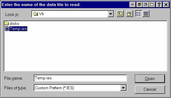
37 VFR Software Program Display Data This is the Display Data menu of the VFR program. It allow the User to Display the data collected, modify the channel data, print it, and save it as an ASCII file. When in this program, the recorder and computer will not communicate. Press the Read File switch to load a data file from disk. The data file should have a suffix of.ies. If not, type in the entire name of the data file. Then press Open. 35
38 36
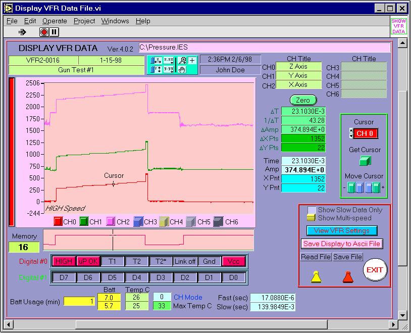
39 Shows the data file name and path. Displays the serial number of the recorder that collected the data, the date of the test, and the test title. The date and time the data was downloaded, and the name of the test operator. The analog channel titles of Ch0, Ch1, and Ch2. The analog channel titles of Ch3, Ch4, Ch5, and Ch6. This is valid for the VFR2 recorder, in Mode 1. The size of the file in K data points. The tool bar for the manipulating the data in the display window. Displays the full data window in the X direction (time). 37
40 Displays the full data window in the Y direction (magnitude). Magnifies the data. Pans the data. The cursor control. Allows grabbing the cursor with the mouse pointer. The amount of time the battery was used during the test. The starting and ending battery voltage during the test. This does not start until the serial link has been disconnected, and is sampled every few minutes. If the test is too short, such as a test where an external T1 pulse turns on the recorder and T2 shuts the recorder down after a short time, these values may be 0. The maximum and minimum temperatures (in degrees Celsius), which occur while recording data during the test. The maximum temperature (in degrees Celsius), which has occurred during the life of the recorder. The Mode of the VFR2 recorder used to collect the data. This does not apply to the VFR1 recorder. Displays the Fast and Slow sampling rates of this data file. 38

41 This is the display window for the data. The top window shows the analog data. The window below it, shows the digital data represented in an analog type of display. The two rows of indicators show the actual digital lines as the cursor is moved around in the window. These buttons determine which data channels are displayed on the graph. CH3 to CH6 are valid for only VFR2, Mode1. The amplitude scale for the current selected data channel is displayed here. The colored bar on the left indicates the channel which has been selected. In this case, channel 0 (the red channel) is the scale, which is shown. 39


42 This section is used to control the cursor. The + button must be pressed to put the graph in the cursor mode. Picking it with the mouse then can move the cursor. This button determines which channel the cursor is active with, and which amplitude scale is displayed. If the data window was zoomed and the Cursor has disappeared, press this button to bring the cursor back into the currently displayed window. The cursor can be moved with the mouse, or my pressing these buttons. The inner blue buttons will move the cursor by one data point. The outer green buttons will move it by 100 data points at a time. As the cursor is moved, the current data point amplitude and time positions are updated and displayed. Both the delta and the actual value are displayed. The Zero button is used to set a reference. Note: The timing information is ONLY VALID in the High Speed areas. Even in the Low Speed areas, each data point you move the 40
43 cursor, the time change will be at the High Speed sampling rate. To allow this display to work with Low Speed sampling rates, the Display Slow Data Only button must be pressed. When this button is pressed, the green displayed is zeroed at that cursor location. When the Zero button is pressed and the cursor is moved, the numbers displayed here will change based on this New zero reference. Effectively, the new values are the delta value from this zero point. X Pts and Y Pts are the actual BIT value of the data point. This displays the actual time, amplitude, and BIT values of the data at the cursor location of the active channel. Note: The Amplitude and the Y Pnt are based on the Zero Bias found in the View VFR Settings. When Show Multi-speed is selected, all of the data is displayed, both the Slow Speed and High Speed data points. Note: When the Show Multi-speed is selected, only the High Speed sampling rate is used to calculated the times when the cursor is moved. When Show Slow Data Only is selected, only the Slow Speed data is displayed. When there is a High Speed event, it is represented as a single spike of date, with the correct magnitude. 41

44 Note: When the Show Slow Data Only is selected, the time is calculated using the Slow Speed sampling rate when the cursor is moved. The digital data is displayed both in an analog graph and as indicators. The cursor position determines which indicators are lit, based on the digital values. This graph shows the digital activity for the data window currently displayed. The red signal is Digital channel #0 and the green signal is Digital channel #1. Digital channel #0 contains the recorder s internal signals. LOW indicates the recorder is sampling data in the Slow Speed rate. HIGH indicates the recorder is sampling in the Fast Speed rate. up OK indicates no internal reset occurred during the test. This should lit at all times. When lit, this indicates that an external T1 pulse has occurred. When lit, this indicates that en external T2 pulse has occurred. 42

45 Note: If the T2 pulse is too narrow, this indicator may not light. This is the latched T2 pulse indicator. This also lights when an external T2 pulse occurs, so if the pulse is too narrow to be recorded by the T2 indicator, the User will still know that an external T2 occurred. It will turn off after the recorder goes back into the slow Speed mode. Indicates the serial link is not connected to the recorder. Indicates the serial link is connected to the recorder. Always OFF. Always ON. Digital Channel #1 contains the 8 User defined digital channels. OFF indicates a low signal and ON indicates a high signal. Indicates at the current cursor position, the data was sampled at the Low Speed rate. Indicates at the current cursor position, the data was sampled at the High Speed rate. 43

46 This section controls the reading and saving of that data file, converting the data to an ASCII data file, changing the current channel settings and viewing the test setup, and displaying the data in High/Slow speeds. When Show Multi-speed is selected, all of the data is displayed, both the Slow Speed and High Speed data points. Note: When the Show Multi-speed is selected, only the High Speed sampling rate is used to calculated the times when the cursor is moved. When Show Slow Data Only is selected, only the Slow Speed data is displayed. When there is a High Speed event, it is represented as a single spike of date, with the correct magnitude. Note: When the Show Slow Data Only is selected, the time is calculated using the Slow Speed sampling rate when the cursor is moved. Allows the User to view how the recorder was programmed for the test. The Channel data can be edited. This is covered in another section of the software manual. Data can be EXPORTED to an ASCII data file in a spreadsheet form for further data analysis. 44

47 When pressed, this display appears and gives several options for making an ASCII data file. This can be aborted by pressing the EXIT button. Note: The display data will be saved in an ASCII file. If YES is selected, the time base in the spreadsheet data file will begin with ZERO time. Otherwise, the current time displayed on the graph will be used. If YES is selected, the data file size is reduced by the Reduction Factor that is entered. For example, if the reduction factor is 10, every 10th data point is saved to the ACSII file, reducing the physical size of the file by 90%. This saves any changes to the data file record. Either the ENTIRE data file can be saved, or just the DISPLAYED data. Loads a data file from the disk. 45
48 Exits the Data Display section of the program 46
49 Encapsulation Encapsulation is important for shock survivability. The general rule for shock survivability is if it can move, it will break. Once the recorder or a battery pack is constructed and tested, it should be stabilized using an encapsulation compound. The Epoxy-casting section below describes the procedure used for the encapsulation. Having encapsulated the recorder and battery, an additional encapsulation is required to physically locate the recorder within the test fixture, fill all of the voids, and prevent any motion during hostile tests. This second encapsulation is described below in Recorder Packaging section. Epoxy-Casting The compound selected for the VFR 1 and the batteries is a epoxy-casting resin manufactured by Emerson and Cuming. A suitable mold should be constructed out of nylon or Teflon to yield the desired final shape. The mold should also include an overflow chamber for expansion of the encapsulating compound during the de-aeration process. The following procedure is an encapsulating example using an epoxy-casting resin manufactured by Emerson and Cuming. Compound Formulation The casting compound is formulated from the materials listed below, taken in the requisite proportions on a weight basis. The tolerance on weights of materials is + 2 percent. Maximum batch size is 90 grams. Part A Stycast 1090SI 100 parts by weight Part B Catalyst 24-LV 23 parts by weight Mold Preparation The mold or housing should be clean and free of contaminants. When the mold is not an integral part of the component, it should be cleaned and coated with a suitable mold release agent and allowed to dry. Container Preparation All mixing or handling containers should be clean and moisture-free. WARNING. The components of the casting compound may be toxic. Hence, adequate ventilation should be provided in the handling of the components to prevent exposure to vapors. Ingestion or skin contact with these materials shall be avoided. If accidental skin contact should occur, the exposed areas should be washed immediately with soap and water. 47
Vorne Industries. 87/719 Analog Input Module User's Manual Industrial Drive Itasca, IL (630) Telefax (630)
 Telefax (630)") Vorne Industries 87/719 Analog Input Module User's Manual 1445 Industrial Drive Itasca, IL 60143-1849 (630) 875-3600 Telefax (630) 875-3609 . 3 Chapter 1 Introduction... 1.1 Accessing Wiring Connections
Vorne Industries 87/719 Analog Input Module User's Manual 1445 Industrial Drive Itasca, IL 60143-1849 (630) 875-3600 Telefax (630) 875-3609 . 3 Chapter 1 Introduction... 1.1 Accessing Wiring Connections
Please feel free to download the Demo application software from analogarts.com to help you follow this seminar.
 Hello, welcome to Analog Arts spectrum analyzer tutorial. Please feel free to download the Demo application software from analogarts.com to help you follow this seminar. For this presentation, we use a
Noise Detector ND-1 Operating Manual
 Noise Detector ND-1 Operating Manual SPECTRADYNAMICS, INC 1849 Cherry St. Unit 2 Louisville, CO 80027 Phone: (303) 665-1852 Fax: (303) 604-6088 Table of Contents ND-1 Description...... 3 Safety and Preparation
Data Acquisition Using LabVIEW
 Experiment-0 Data Acquisition Using LabVIEW Introduction The objectives of this experiment are to become acquainted with using computer-conrolled instrumentation for data acquisition. LabVIEW, a program
TL-2900 AMMONIA & NITRATE ANALYZER DUAL CHANNEL
 TL-2900 AMMONIA & NITRATE ANALYZER DUAL CHANNEL DATA ACQUISITION SYSTEM V.15.4 INSTRUCTION MANUAL Timberline Instruments, LLC 1880 S. Flatiron Ct., Unit I Boulder, Colorado 80301 Ph: (303) 440-8779 Fx:
4.9 BEAM BLANKING AND PULSING OPTIONS
 4.9 BEAM BLANKING AND PULSING OPTIONS Beam Blanker BNC DESCRIPTION OF BLANKER CONTROLS Beam Blanker assembly Electron Gun Controls Blanker BNC: An input BNC on one of the 1⅓ CF flanges on the Flange Multiplexer
SXGA096 DESIGN REFERENCE BOARD
 SXGA096 DESIGN REFERENCE BOARD For Use with all emagin SXGA096 OLED Microdisplays USER S MANUAL VERSION 1.0 TABLE OF CONTENTS D01-501152-01 SXGA096 Design Reference Board User s Manual i 1. INTRODUCTION...
16 Stage Bi-Directional LED Sequencer
 16 Stage Bi-Directional LED Sequencer The bi-directional sequencer uses a 4 bit binary up/down counter (CD4516) and two "1 of 8 line decoders" (74HC138 or 74HCT138) to generate the popular "Night Rider"
JAMAR TRAX RD Detector Package Power Requirements Installation Setting Up The Unit
 JAMAR TRAX RD The TRAX RD is an automatic traffic recorder designed and built by JAMAR Technologies, Inc. Since the unit is a Raw Data unit, it records a time stamp of every sensor hit that occurs during
Operating Instructions
 CNTX Contrast sensor Operating Instructions CAUTIONS AND WARNINGS SET-UP DISTANCE ADJUSTMENT: As a general rule, the sensor should be fixed at a 15 to 20 angle from directly perpendicular to the target
EECS145M 2000 Midterm #1 Page 1 Derenzo
 UNIVERSITY OF CALIFORNIA College of Engineering Electrical Engineering and Computer Sciences Department EECS 145M: Microcomputer Interfacing Laboratory Spring Midterm #1 (Closed book- calculators OK) Wednesday,
Solutions to Embedded System Design Challenges Part II
 Solutions to Embedded System Design Challenges Part II Time-Saving Tips to Improve Productivity In Embedded System Design, Validation and Debug Hi, my name is Mike Juliana. Welcome to today s elearning.
Triple RTD. On-board Digital Signal Processor. Linearization RTDs 20 Hz averaged outputs 16-bit precision comparator function.
 Triple RTD SMART INPUT MODULE State-of-the-art Electromagnetic Noise Suppression Circuitry. Ensures signal integrity even in harsh EMC environments. On-board Digital Signal Processor. Linearization RTDs
TASTEPROBE Type DTP-1. Pre-amplifier for recording from contact chemosensilla INSTRUCTIONS
 TASTEPROBE Type DTP-1 Pre-amplifier for recording from contact chemosensilla INSTRUCTIONS SYNTECH 2002 Hilversum, The Netherlands Reproduction of text and/or drawings is permitted for personal use. The
Logic Analyzer Auto Run / Stop Channels / trigger / Measuring Tools Axis control panel Status Display
 Logic Analyzer The graphical user interface of the Logic Analyzer fits well into the overall design of the Red Pitaya applications providing the same operating concept. The Logic Analyzer user interface
Quick Operation Guide of LTN7700/7600 Series NVR
 Quick Operation Guide of LTN7700/7600 Series NVR UD.6L0202B0042A02 Thank you for purchasing our product. If there is any question or request, please do not hesitate to contact dealer. This manual is applicable
Operating Instructions
 Operating Instructions HAEFELY TEST AG KIT Measurement Software Version 1.0 KIT / En Date Version Responsable Changes / Reasons February 2015 1.0 Initial version WARNING Introduction i Before operating
PRELIMINARY INFORMATION. Professional Signal Generation and Monitoring Options for RIFEforLIFE Research Equipment
 Integrated Component Options Professional Signal Generation and Monitoring Options for RIFEforLIFE Research Equipment PRELIMINARY INFORMATION SquareGENpro is the latest and most versatile of the frequency
013-RD
 Engineering Note Topic: Product Affected: JAZ-PX Lamp Module Jaz Date Issued: 08/27/2010 Description The Jaz PX lamp is a pulsed, short arc xenon lamp for UV-VIS applications such as absorbance, bioreflectance,
NanoGiant Oscilloscope/Function-Generator Program. Getting Started
 Getting Started Page 1 of 17 NanoGiant Oscilloscope/Function-Generator Program Getting Started This NanoGiant Oscilloscope program gives you a small impression of the capabilities of the NanoGiant multi-purpose
The BAT WAVE ANALYZER project
 The BAT WAVE ANALYZER project Conditions of Use The Bat Wave Analyzer program is free for personal use and can be redistributed provided it is not changed in any way, and no fee is requested. The Bat Wave
KF200 PORTABLE MANUAL
 KF200 PORTABLE MANUAL THIS MANUAL CONTAINS: KF200 OPERATORS MANUAL KF200 GRAIN SOFTWARE MANUAL SPECIAL NOTE BOONE CABLE WORKS & ELECTRONICS, INC. 1773-219TH LANE - P.O. BOX 369 READ THIS ENTIRE BOOKLET
DSIM-GI Installation Guide Revision P
 Installation Guide Revision P 1. Quick Start Instructions for Single Pilot AGC Operatation 1. With the ADU jumper in Auto position, turn ADU pot to MIN amplifier output level. Then place the ADU jumper
Oscilloscope Guide Tektronix TDS3034B & TDS3052B
 Tektronix TDS3034B & TDS3052B Version 2008-Jan-1 Dept. of Electrical & Computer Engineering Portland State University Copyright 2008 Portland State University 1 Basic Information This guide provides basic
ME EN 363 ELEMENTARY INSTRUMENTATION Lab: Basic Lab Instruments and Data Acquisition
 ME EN 363 ELEMENTARY INSTRUMENTATION Lab: Basic Lab Instruments and Data Acquisition INTRODUCTION Many sensors produce continuous voltage signals. In this lab, you will learn about some common methods
Auxiliary states devices
 22 Auxiliary states devices When sampling using multiple frame states, Signal can control external devices such as stimulators in addition to switching the 1401 outputs. This is achieved by using auxiliary
EAN-Performance and Latency
 EAN-Performance and Latency PN: EAN-Performance-and-Latency 6/4/2018 SightLine Applications, Inc. Contact: Web: sightlineapplications.com Sales: sales@sightlineapplications.com Support: support@sightlineapplications.com
NOTICE: This document is for use only at UNSW. No copies can be made of this document without the permission of the authors.
 Brüel & Kjær Pulse Primer University of New South Wales School of Mechanical and Manufacturing Engineering September 2005 Prepared by Michael Skeen and Geoff Lucas NOTICE: This document is for use only
Show Designer 3. Software Revision 1.15
 Show Designer 3 Software Revision 1.15 OVERVIEW... 1 REAR PANEL CONNECTIONS... 1 TOP PANEL... 2 MENU AND SETUP FUNCTIONS... 3 CHOOSE FIXTURES... 3 PATCH FIXTURES... 3 PATCH CONVENTIONAL DIMMERS... 4 COPY
Dragonfly Quad. User Manual V1.4. Order code: EQLED101
 Dragonfly Quad User Manual V1.4 Order code: EQLED101 Safety advice WARNING FOR YOUR OWN SAFETY, PLEASE READ THIS USER MANUAL CAREFULLY BEFORE YOUR INITIAL START-UP! Before your initial start-up, please
Element 78 MPE-200. by Summit Audio. Guide To Operations. for software version 1.23
 Element 78 MPE-200 by Summit Audio Guide To Operations for software version 1.23 TABLE OF CONTENTS IMPORTANT SAFETY AND GROUNDING INSTRUCTIONS COVER 1. UNPACKING AND CONNECTING...3 AUDIO CONNECTIONS...4
Quick-Start for READ30
 Quick-Start for READ30 The program READ30 was written for the purpose of reading and configuring the digital pressure-transmitter of the series 30. The two features are divided into the following parts:
Night Hawk Firing System User s Manual
 Firmware Version 2.53 Page 1 of 37 Table of Contents Features of the Night Hawk Panel... 4 A reminder on the safe use of Electronic Pyrotechnic Firing Systems... 5 Night Hawk Firing Panel Controls... 6
Experiment # 4 Counters and Logic Analyzer
 EE20L - Introduction to Digital Circuits Experiment # 4. Synopsis: Experiment # 4 Counters and Logic Analyzer In this lab we will build an up-counter and a down-counter using 74LS76A - Flip Flops. The
AES-402 Automatic Digital Audio Switcher/DA/Digital to Analog Converter
 Broadcast Devices, Inc. AES-402 Automatic Digital Audio Switcher/DA/Digital to Analog Converter Technical Reference Manual Broadcast Devices, Inc. Tel. (914) 737-5032 Fax. (914) 736-6916 World Wide Web:
Evolution Digital HD Set-Top Box Important Safety Instructions
 Evolution Digital HD Set-Top Box Important Safety Instructions 1. Read these instructions. 2. Keep these instructions. 3. Heed all warnings. 4. Follow all instructions. 5. Do not use this apparatus near
MULTIDYNE INNOVATIONS IN TELEVISION TESTING & DISTRIBUTION DIGITAL VIDEO, AUDIO & DATA FIBER OPTIC MULTIPLEXER TRANSPORT SYSTEM
 MULTIDYNE INNOVATIONS IN TELEVISION TESTING & DISTRIBUTION INSTRUCTION MANUAL DVM-1000 DIGITAL VIDEO, AUDIO & DATA FIBER OPTIC MULTIPLEXER TRANSPORT SYSTEM MULTIDYNE Electronics, Inc. Innovations in Television
HD Digital Set-Top Box Quick Start Guide
 HD Digital Set-Top Box Quick Start Guide Eagle Communications HD Digital Set-Top Box Important Safety Instructions WARNING TO REDUCE THE RISK OF FIRE OR ELECTRIC SHOCK, DO NOT EXPOSE THIS PRODUCT TO RAIN
SPX-5600 Series. Operations Manual. Suprex Reader Extender - RF Wireless Interface SPX-5600MAN. Page 1 of 20
 SPX-5600 Series Operations Manual Suprex Reader Extender - RF Wireless Interface SPX-5600MAN Page 1 of 20 SPX-5600 Series: Cypress Suprex SPX-5600 Series This manual covers the operation and setup of the
Re: ENSC 370 Project Physiological Signal Data Logger Functional Specifications
 School of Engineering Science Simon Fraser University V5A 1S6 versatile-innovations@sfu.ca February 12, 1999 Dr. Andrew Rawicz School of Engineering Science Simon Fraser University Burnaby, BC V5A 1S6
0.56" 4 Digital Blue LED Panel Meter (rescalable) User s Guide
 User s Guide") 0.56" 4 Digital Blue LED Panel Meter (rescalable) User s Guide 2004-2009 Sure Electronics Inc. ME-SP037B_Ver1.0 0.56" 4 DIGITAL BLUE LED PANEL METER (RESCALABLE) USER S GUIDE Table of Contents Chapter
0.56" 4 Digital Blue LED Panel Meter (rescalable) User s Guide 2004-2009 Sure Electronics Inc. ME-SP037B_Ver1.0 0.56" 4 DIGITAL BLUE LED PANEL METER (RESCALABLE) USER S GUIDE Table of Contents Chapter
Twin Beam Scale Operation Manual. April Specialists in Industrial Weighing
 Twin Beam Scale Operation Manual April 2007 Digi-Tron Specialists in Industrial Weighing www.digitronbalancas.com.br Twin Beam Scale Operation Manual Introduction Dear User, This manual contains operating
Technical data. General specifications. Indicators/operating means
 Model Number Single head system Features Sensor head bidirectional and rotatable Function indicators visible from all directions Quick mounting bracket Selectable sound lobe width Programmable Diagrams
SNG-2150C User s Guide
 SNG-2150C User s Guide Avcom of Virginia SNG-2150C User s Guide 7730 Whitepine Road Revision 001 Richmond, VA 23237 USA GENERAL SAFETY If one or more components of your earth station are connected to 120
Troubleshooting. 1. Symptom: Status indicator (Red LED) on SSR is constant on. 2. Symptom: Output indicator (Yellow LED) on SSR is flashing.
 on SSR is constant on. 2. Symptom: Output indicator (Yellow LED) on SSR is flashing.") Product Data Electrical Data SST (Transmitter) SSR (Receiver) Supply voltage 18 30 V dc Max. Voltage ripple 15 % (within supply range) Current consumption 100 ma (RMS) 75 ma Digital - 100 ma Max. outputs
Product Data Electrical Data SST (Transmitter) SSR (Receiver) Supply voltage 18 30 V dc Max. Voltage ripple 15 % (within supply range) Current consumption 100 ma (RMS) 75 ma Digital - 100 ma Max. outputs
RF4432 wireless transceiver module
 RF4432 wireless transceiver module 1. Description RF4432 adopts Silicon Lab Si4432 RF chip, which is a highly integrated wireless ISM band transceiver. The features of high sensitivity (-121 dbm), +20
medlab One Channel ECG OEM Module EG 01000
 medlab One Channel ECG OEM Module EG 01000 Technical Manual Copyright Medlab 2012 Version 2.4 11.06.2012 1 Version 2.4 11.06.2012 Revision: 2.0 Completely revised the document 03.10.2007 2.1 Corrected
Model 6010 Four Channel 20-Bit Audio ADC Data Pack
 Model 6010 Four Channel 20-Bit Audio ADC Data Pack Revision 3.1 SW v1.0.0 This data pack provides detailed installation, configuration and operation information for the Model 6010 Four Channel 20-bit Audio
OSD. EXECUTIVE / MiniDome USERS MANUAL. USING THE MOTOSAT DISH POINTING SYSTEM EXECUTIVE / MiniDome OSD
 EXECUTIVE / MiniDome OSD USERS MANUAL USING THE MOTOSAT DISH POINTING SYSTEM EXECUTIVE / MiniDome OSD MotoSAT Corporation Created April 22, 2003 1-800-247-7486 CONGRATULATIONS! on your purchase of your
Fusion 120 Zoom. User Manual. Order code: EQLED068
 Fusion 120 Zoom User Manual Order code: EQLED068 Safety advice WARNING FOR YOUR OWN SAFETY, PLEASE READ THIS USER MANUAL CAREFULLY BEFORE YOUR INITIAL START-UP! Before your initial start-up, please make
Telemetry Receiver Installation Guide
 BBV Telemetry Receiver Installation Guide Models covered Rx200 Building Block Video Ltd., Unit 1, Avocet Way, Diplocks Industrial Estate, Hailsham, East Sussex, UK. Tel: +44 (0)1323 842727 Fax: +44 (0)1323
RD RACK MOUNT DIMMER OWNERS MANUAL VERSION /09/2011
 RD - 122 RACK MOUNT DIMMER OWNERS MANUAL VERSION 1.3 03/09/2011 Page 2 of 14 TABLE OF CONTENTS UNIT DESCRIPTION AND FUNCTIONS 3 POWER REQUIREMENTS 3 INSTALLATION 3 PLACEMENT 3 POWER CONNECTIONS 3 OUTPUT
SC26 Magnetic Field Cancelling System
 SPICER CONSULTING SYSTEM SC26 SC26 Magnetic Field Cancelling System Makes the ambient magnetic field OK for electron beam tools in 300 mm wafer fabs Real time, wideband cancelling from DC to > 9 khz fields
Personal Information Page
 Rev. 08.29.07 Personal Information Page Installing Dealer Name Date of Installation Day Month Year Type of System Executive MD500 MD1000.2 MHDTV MD5Slim MSD60 Freedom (not recommended) Serial Number of
Transmitter Interface Program
 Transmitter Interface Program Operational Manual Version 3.0.4 1 Overview The transmitter interface software allows you to adjust configuration settings of your Max solid state transmitters. The following
Integrated Circuit for Musical Instrument Tuners
 Document History Release Date Purpose 8 March 2006 Initial prototype 27 April 2006 Add information on clip indication, MIDI enable, 20MHz operation, crystal oscillator and anti-alias filter. 8 May 2006
Part No. ENC-LAB01 Users Manual Introduction EncoderLAB
 PCA Incremental Encoder Laboratory For Testing and Simulating Incremental Encoder signals Part No. ENC-LAB01 Users Manual The Encoder Laboratory combines into the one housing and updates two separate encoder
EXPERIMENT #6 DIGITAL BASICS
 EXPERIMENT #6 DIGITL SICS Digital electronics is based on the binary number system. Instead of having signals which can vary continuously as in analog circuits, digital signals are characterized by only
ORPHEUS ZERO U S E R M A N U A L
 ORPHEUS ZERO U S E R M A N U A L I N T R O D U C T I O N FEATURES Class 1 product CD drive (ORPHEUS ZERO Drive) or player (ORPHEUS ZERO Player) Multiple formats reader : CD, CD-R, CD-RW Software controlled
Mission. Lab Project B
 Mission You have been contracted to build a Launch Sequencer (LS) for the Space Shuttle. The purpose of the LS is to control the final sequence of events starting 15 seconds prior to launch. The LS must
Operating Instructions ACX-Series Digital Aircraft Cable Tension Meter
 733 S. Bowen Street Longmont, CO 80501 USA Phone: (303) 702-1980 Fax: (303) 702-1982 E-mail: sales@tensitron.com Web Site: www.tensitron.com Operating Instructions ACX-Series Digital Aircraft Cable Tension
SC24 Magnetic Field Cancelling System
 SPICER CONSULTING SYSTEM SC24 SC24 Magnetic Field Cancelling System Makes the ambient magnetic field OK for the electron microscope Adapts to field changes within 100 µs Touch screen intelligent user interface
SINGLE ZONE CLIMATE ZONING SYSTEM. Technical Manual. Polyaire Pty Ltd
 SINGLE ZONE CLIMATE ZONING SYSTEM Technical Manual Polyaire Pty Ltd 11-13 White Road GEPPS CROSS South Australia, 5094 Tel: (08) 8349 8466 Fax: (08) 8349 8446 www.polyaire.com.au CONTENTS Features 1 Application
Overview of All Pixel Circuits for Active Matrix Organic Light Emitting Diode (AMOLED)
") Chapter 2 Overview of All Pixel Circuits for Active Matrix Organic Light Emitting Diode (AMOLED) ---------------------------------------------------------------------------------------------------------------
Chapter 2 Overview of All Pixel Circuits for Active Matrix Organic Light Emitting Diode (AMOLED) ---------------------------------------------------------------------------------------------------------------
RF4432F27 wireless transceiver module
 RF4432F27 wireless transceiver module 1. Description RF4432F27 is 500mW RF module embedded with amplifier and LNA circuit. High quality of component, tightened inspection and long term test make this module
Commander 384. w w w. p r o l i g h t. c o. u k U S E R M A N U A L
 Commander 384 w w w. p r o l i g h t. c o. u k U S E R M A N U A L 1, Before you begin 1.1: Safety warnings...2 3 1.2: What is included...4 1.3: Unpacking instructions...4 2, Introduction 2.1: Features...4
DM1624, DM1612, DM812
 Installation Guide Hardware and Software DM Series Digital Processors models DM1624, DM1612, DM812 LECTROSONICS, INC. 1 Installation Specific Information Only This guide covers only installation related
R5 RIC Quickstart R5 RIC. R5 RIC Quickstart. Saab TransponderTech AB. Appendices. Project designation. Document title. Page 1 (25)
") Appendices 1 (25) Project designation R5 RIC Document title CONTENTS 2 (25) 1 References... 4 2 Dimensions... 5 3 Connectors... 6 3.1 Power input... 6 3.2 Video I... 6 3.3 Video Q... 6 3.4 Sync... 6 3.5
Appendices 1 (25) Project designation R5 RIC Document title CONTENTS 2 (25) 1 References... 4 2 Dimensions... 5 3 Connectors... 6 3.1 Power input... 6 3.2 Video I... 6 3.3 Video Q... 6 3.4 Sync... 6 3.5
DS-7200HVI/HFI-SH Series DVR Quick Operation Guide
 DS-7200HVI/HFI-SH Series DVR Quick Operation Guide UD.6L0202B0019A01 Thank you for purchasing our product. If there is any question or request, please do not hesitate to contact dealer. This manual is
SC24 Magnetic Field Cancelling System
 SPICER CONSULTING SYSTEM SC24 SC24 Magnetic Field Cancelling System Makes the ambient magnetic field OK for the electron microscope Adapts to field changes within 100 µs Touch screen intelligent user interface
REMOTE DISPLAY WIRELESS DECODER MK II
 REMOTE DISPLAY WIRELESS DECODER MK II INSTALLATION MANUAL Part No. LED-DEC 1. Contents 1. Contents... 1 2. Equipment List... 2 3. Overview... 2 Introduction... 2 Location Selection **Important **... 2
TV Character Generator
 TV Character Generator TV CHARACTER GENERATOR There are many ways to show the results of a microcontroller process in a visual manner, ranging from very simple and cheap, such as lighting an LED, to much
Lab experience 1: Introduction to LabView
 Lab experience 1: Introduction to LabView LabView is software for the real-time acquisition, processing and visualization of measured data. A LabView program is called a Virtual Instrument (VI) because
CI-218 / CI-303 / CI430
 CI-218 / CI-303 / CI430 Network Camera User Manual English AREC Inc. All Rights Reserved 2017. l www.arec.com All information contained in this document is Proprietary Table of Contents 1. Overview 1.1
V6118 EM MICROELECTRONIC - MARIN SA. 2, 4 and 8 Mutiplex LCD Driver
 EM MICROELECTRONIC - MARIN SA 2, 4 and 8 Mutiplex LCD Driver Description The is a universal low multiplex LCD driver. The version 2 drives two ways multiplex (two blackplanes) LCD, the version 4, four
imso-104 Manual Revised August 5, 2011
 imso-104 Manual Revised August 5, 2011 Section 1 Getting Started SAFETY 1.10 Quickstart Guide 1.20 SAFETY 1.30 Compatibility 1.31 Hardware 1.32 Software Section 2 How it works 2.10 Menus 2.20 Analog Channel
Cisco Spectrum Expert Software Overview
 CHAPTER 5 If your computer has an 802.11 interface, it should be enabled in order to detect Wi-Fi devices. If you are connected to an AP or ad-hoc network through the 802.11 interface, you will occasionally
DIGITAL ELECTRONICS: LOGIC AND CLOCKS
 DIGITL ELECTRONICS: LOGIC ND CLOCKS L 6 INTRO: INTRODUCTION TO DISCRETE DIGITL LOGIC, MEMORY, ND CLOCKS GOLS In this experiment, we will learn about the most basic elements of digital electronics, from
OPERATION AND MAINTENANCE
 BAS MS/TP Enabled OPERATION AND MAINTENANCE An Company Contents Powering Up For The First Time... 3 Setting MSTP Communication Parameters... 4 Changing the MSTP Address... 4 Changing the BACNET ID... 5
GFT channel Time Interval Meter
 Key Features Five-channel Time-Interval Meter: One Start and four Stops - 13 picosecond resolution - < 50 picosecond RMS jitter - > 100 second range - 10 MHz sample rate per channel Common GATE input Input
Table of Contents. Versa TILE & Versa DRIVE D2 Quick Start Manual
 Versa TILE & Versa DRIVE D2 Table of Contents 1. Introduction 2 2. Versa TILE Assembly & Cabling 2 3. Computer & Versa DRIVE Connections 2 4. RasterMAPPER 3 5. Buffer Board 4 6. Testing the System 5 7.
4830A Accelerometer simulator Instruction manual. IM4830A, Revision E1
 4830A Accelerometer simulator Instruction manual IM4830A, Revision E1 IM4830, Page 2 The ENDEVCO Model 4830A is a battery operated instrument that is used to electronically simulate a variety of outputs
Telemetry Receiver Installation Guide
 BBV Telemetry Receiver Installation Guide Models covered Rx400P Building Block Video Ltd., Unit 1, Avocet Way, Diplocks Industrial Estate, Hailsham, East Sussex, UK. Tel: +44 (0)1323 842727 Fax: +44 (0)1323
OWNERS MANUAL LUNATEC V3 MICROPHONE PREAMPLIFIER AND A/D CONVERTER
 OWNERS MANUAL LUNATEC V3 MICROPHONE PREAMPLIFIER AND A/D CONVERTER LUNATEC 35 +48 35 +48 30 40 30 40 0 25 45 25 45 3 192 1 1 6 176.4 20 50 20 50 9 96 12 PEAK 88.2 55 55 RESET 48 10 60 2 10 60 2 21 44.1
Ocean Sensor Systems, Inc. Wave Staff, OSSI F, Water Level Sensor With 0-5V, RS232 & Alarm Outputs, 1 to 20 Meter Staff
 Ocean Sensor Systems, Inc. Wave Staff, OSSI-010-002F, Water Level Sensor With 0-5V, RS232 & Alarm Outputs, 1 to 20 Meter Staff General Description The OSSI-010-002E Wave Staff is a water level sensor that
B. The specified product shall be manufactured by a firm whose quality system is in compliance with the I.S./ISO 9001/EN 29001, QUALITY SYSTEM.
 VideoJet 8000 8-Channel, MPEG-2 Encoder ARCHITECTURAL AND ENGINEERING SPECIFICATION Section 282313 Closed Circuit Video Surveillance Systems PART 2 PRODUCTS 2.01 MANUFACTURER A. Bosch Security Systems
Weighing Scale. 10key&12key User manual
 Weighing Scale 10&12 User manual EXCELL PRECISION CO., LTD. 2014. All rights reserved worldwide. The information contained herein is the property of EXCELL PRECISION CO., LTD. and is supplied without liability
Model 7600 HD/SD Embedder/ Disembedder Data Pack
 Model 7600 HD/SD Embedder/ Disembedder Data Pack E NSEMBLE D E S I G N S Revision 2.1 SW v2.0.1 This data pack provides detailed installation, configuration and operation information for the 7600 HD/SD
Operating Manual. 50mW C-Band EDFA with GPIB and RS232 Interface
 Fibotec Fiberoptics GmbH Herpfer Str. 40 98617 Meiningen Germany Tel. +49 3693 8813-200 Fax. +49 3693 8813-201 www.fibotec.com Operating Manual 50mW C-Band EDFA with GPIB and RS232 Interface (Version 1.1
WaveView. and. WaveCal
 WaveView and WaveCal WaveView Introduction 1 Software Startup & Sample Acquisition 3 Startup WaveView 3 Configure Channels 5 Configure Acquisition 6 Collect and View Data 6 Store Data [and View File Data]
A FOUR GAIN READOUT INTEGRATED CIRCUIT : FRIC 96_1
 A FOUR GAIN READOUT INTEGRATED CIRCUIT : FRIC 96_1 J. M. Bussat 1, G. Bohner 1, O. Rossetto 2, D. Dzahini 2, J. Lecoq 1, J. Pouxe 2, J. Colas 1, (1) L. A. P. P. Annecy-le-vieux, France (2) I. S. N. Grenoble,
VNS2200 Amplifier & Controller Installation Guide
 VNS2200 Amplifier & Controller Installation Guide VNS2200 Amplifier & Controller Installation 1. Determine the installation location for the VNS2200 device. Consider the following when determining the
DT3162. Ideal Applications Machine Vision Medical Imaging/Diagnostics Scientific Imaging
 Compatible Windows Software GLOBAL LAB Image/2 DT Vision Foundry DT3162 Variable-Scan Monochrome Frame Grabber for the PCI Bus Key Features High-speed acquisition up to 40 MHz pixel acquire rate allows
BME 3512 Biomedical Laboratory Equipment List
 BME 3512 Biomedical Laboratory Equipment List Agilent E3630A DC Power Supply Agilent 54622A Digital Oscilloscope Agilent 33120A Function / Waveform Generator APPA 95 Digital Multimeter Component Layout
MIE 402: WORKSHOP ON DATA ACQUISITION AND SIGNAL PROCESSING Spring 2003
 MIE 402: WORKSHOP ON DATA ACQUISITION AND SIGNAL PROCESSING Spring 2003 OBJECTIVE To become familiar with state-of-the-art digital data acquisition hardware and software. To explore common data acquisition
FRQM-2 Frequency Counter & RF Multimeter
 FRQM-2 Frequency Counter & RF Multimeter Usage Instructions Firmware v2.09 Copyright 2007-2011 by ASPiSYS Ltd. Distributed by: ASPiSYS Ltd. P.O.Box 14386, Athens 11510 (http://www.aspisys.com) Tel. (+30)
American DJ. Show Designer. Software Revision 2.08
 American DJ Show Designer Software Revision 2.08 American DJ 4295 Charter Street Los Angeles, CA 90058 USA E-mail: support@ameriandj.com Web: www.americandj.com OVERVIEW Show Designer is a new lighting
Integration of Virtual Instrumentation into a Compressed Electricity and Electronic Curriculum
 Integration of Virtual Instrumentation into a Compressed Electricity and Electronic Curriculum Arif Sirinterlikci Ohio Northern University Background Ohio Northern University Technological Studies Department
Installation & Operation Manual. BEC PM1 Controller Time/Flow/Volume Controller. Water Control Solutions
 Installation & Operation Manual BEC PM1 Controller Time/Flow/Volume Controller Water Control Solutions Table of Contents Introduction 4 Chapter 1 Technical Data and I/O Connections 6 DC Solenoid 6 Power
Be sure to run the vehicle engine while using this unit to avoid battery exhaustion.
 CAUTION: TO REDUCE THE RISK OF ELECTRIC SHOCK DO NOT REMOVE COVER (OR BACK) NO USER-SERVICEABLE PARTS INSIDE REFER SERVICING TO QUALIFIED SERVICE PERSONNE; Please Read all of these instructions regarding