Mitsubishi WS-55859: Changing out your capacitors when your set will not Turn On, the "Green Light is Flashing" and it won't give you an Error Code.
|
|
|
- Rudolph McDonald
- 6 years ago
- Views:
Transcription
1 Mitsubishi WS-55859: Changing out your capacitors when your set will not Turn On, the "Green Light is Flashing" and it won't give you an Error Code. Taken From thank you Don ;-) Note: When you view your capacitors for the first, They will not appear to be damaged or puffy. This message board and *************** just saved me either $ or $ To all the contributors who posted photos and instructions on the dreaded "flashing green light" T-H-A-N-K Y-O-U! As of Firday night. I had the TV re-assembled (with new capacitors installed) and I had almost conceded and given up. When I plugged the TV back in I had no power and no flashing green light. NOTHING. I've spent the rest of weekend using CNET.com to read reviews on the editor's choice awards for plasma sets and wondering how I'd pay for a 52" p Plasma. Sunday I took the TV apart (not wanting to give up) all the way down to removing the brand new capacitors. Desoldered them, took them out and started all over again. This time when I plugged the power cord in I instantly heard juice go through the set. Walked around to the front and...omg I had a flashing green light. In about 30 seonds the green light went out. THE MOMENT OF TRUTH! I pushed the power knob on the front of the set AND... BAM -I got a picture. The WS has 7 capacitors instead of the "four" that have been mentioned here, on other Mitsubishi sets. They are mounted on a 4" square daughter board inside the DM Module shielded case. Total cost of the repairs were around $ Seventy five dollars of that came from a universal arm style light that has a big round magnifying glass. get capacitors here uf 16v 105C Capacitors 1 - Magnifying Lamp 1 - Weller Soldering Iron " Width (Pro Wick Desoldering Braid) Size #3
2 1 - ROSIN CORE SOLDER INSTRUCTIONS: (EXPLAINED LIKE YOU HAVE NO SOLDERING EXPERIENCE) I had never desoldered a circuit board in my life. On my own I finally figured out if you place the desolder braid flat on the board next to the pin (you want to desolder) place the tip of your iron directly on the desolder braid and not directly on the solder. You can briefly touch the solder just to get the wick action started. Have the desolder braid touching the base of the mound of solder your wanting to remove. Press your iron directly onto the braid with the braid barely touching the mound of solder. When iron is hot enough you will see the braid begin to suck the melting solder like a wick. When placing the solder on the new pins you need a third hand to hold the capacitors snuggly against the circuit board. To do this, I placed the capacitor in place with the two pins sticking through the board. I grabbed one pin with a set of surgical hemistats. Because hemistats are slightly arched, it allows the hemistats to grab one pin and the other clearly visible to solder while the hemistats hold the capacitor in place. Allow it to cool, remove the hemistats and repeat the process till all capacitors are in place. A TIP ON SOLDERING: On your first drip of solder onto each pin, make sure it's as tiny as possible. VERY TINY! Get it on the pin and set the solder supply to the side. Work that tiny drip with the tip of your iron. You want to work that first drip and get it to suck into the hole of the circuit board around the capacitor's pin. I didn't pay special attention to this on my first pass and my drips were to large. This can lead to loose pins and loose capacitors. The only way to get solder deep into the hole the pins are sticking through is use a very tiny amount of solder. While your DM Module is completely out and laying on a slightly elevated surface. (I used a plano fishing tackle box) Observe the bottom plastic guide that the DM Module rest in. Toward the outer edge of the TV's back, you will see a narrow slot in the plastic guide. In my photos I refer to it as a plastic receptacle. Now pick up the faceplate you have removed from the DM Module. At the bottom of the faceplate is a shark fin shaped piece of the faceplate. Make sure that lines up and slides back into the the plastic guide properly.
3 If you don't...your DM Module will seem to not want to slide back in properly. It also acts as a guide to make a copper contact strip to engage properly with proper surface contact. Removing the DM Module is only slightly tricky. Because your not going to disconnect any wire connectors from any of the circuit boards. The wire bundles leaving the DM Module have just so much length and will not allow you to slide the DM Module out. So there is a work around to get the DM Module out. IN my photos, I show you how to rotate the DM Module "in place" and rotating it out of it's resting place. Above the DM Module is the upper plastic guide that prevents you from doing this rotate "in place" maneuver. The upper plastic guide must be removed by removing two screws. To get to these screws, just above the plastic guide is a inner wooden shelf that is laying in the TV horizontally. I removed four screws holding it inside the TV's case, and then removed the wooden shelf. (see photos). Now you can easily remove the upper plastic guide. STEP BY STEP GUIDE WITH PHOTOS: STEP 1) The DM Module loose. But it can't be rotate out because of the upper plastic guide.

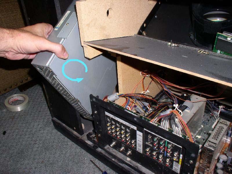
4 STEP 2) How the DM Module is rotated out of the TV case. Allow the wires entering the DM Module to be an axis point of the rotation. That way they barely move and don't get snagged or stretched.
5

6 STEP 3) The DM Module out and the side cover of the metal housing removed.

7 STEP 4) My setup to do the soldering work.

8 STEP 5) Up Close of the daughter board and the seven capacitors on Mits WS

9 STEP 6) The daughter board unscrewed and flipped over where you will be soldering.

10 STEP 7) The Upper Plastic Guide that must be removed to rotate the DM Module out of the TV set.
 and getting the upper plastic guide out")
11 STEP 8) Get this wooden horizontal shelf out (4 screws) and getting the upper plastic guide out becomes easy.

12 STEP 9) Helpful Hint about the wooden shelf and the platic guide that both need to be removed. When I put it all back together and plugged the TV in, I heard the juice surge through the TV. Went around to the front and my green light was flashing. It flashed for about 30 seconds. It then when out. I hit the power and the TV came to life. I found myself very fortunate that I found answers on here, and I ve never soldered a single circuit board in my life. Mitsubishi...You still suck major donkey D&^%#S. My next TV will be either Pioneer, Sony or Panasonic. I've been very disappointed with the two Mits tv's that I've purchased. One broke when it was 6 months old. I don't care what the new standard of "quality" is.
13 My philosophy is... I buy a TV...let's say from TWEETER and it's a Mitsubishi.
Repairing Mitsubishi WS Blinking green light fuse replacement
 Repairing Mitsubishi WS-65511 Blinking green light fuse replacement Repair of the green blinking light by replacing the capacitors on the DM board. This repair can also be performed on the following models:
DIY. How to install a PL-259 connector. Parts list: Tools list: Worthwhile projects you can build on your own
 DIY Worthwhile projects you can build on your own Just like you, I often need to install a PL-259 connector on a length of coax (coaxial cable), to attach it to the mating SO-239 connector of a mobile
Atari PICO Composite Mod Board Installation Instructions:
 Atari PICO Composite Mod Board Installation Instructions: Installation Guide 6 Switch Atari 2600 6 Switch Video Mod Installation Guide Disclaimer: I am not responsible for any damage done to your Atari.
MAKE AN RGB CONTROL KNOB.
 MAKE AN RGB CONTROL KNOB. This is a knob based colour changing controller that uses a custom programmed microcontroller to pack a lot of features into a small affordable kit. The module can drive up to
K Service Source. Apple High-Res Monochrome Monitor
 K Service Source Apple High-Res Monochrome Monitor K Service Source Specifications Apple High-Resolution Monochrome Monitor Specifications Characteristics - 1 Characteristics Picture Tube 12-in. diagonal
imac Intel 27" EMC 2546 isight Camera and Microphone Cable Replacement
 imac Intel 27" EMC 2546 isight Camera and Microphone Cable Replacement Replace the isight/microphone cable in your Late 2012 27" imac. Written By: Andrew Optimus Goldberg ifixit CC BY-NC-SA www.ifixit.com
imac Intel 27" EMC 2639 Display Replacement
 imac Intel 27" EMC 2639 Display Replacement Replace the Display in your imac Intel 27" EMC 2639. Rédigé par: Walter Galan ifixit CC BY-NC-SA fr.ifixit.com Page 1 de 16 INTRODUCTION Removing the display
K Service Source. Apple High-Res Monochrome Monitor
 K Service Source Apple High-Res Monochrome Monitor K Service Source Specifications Apple High-Resolution Monochrome Monitor Specifications Characteristics - 1 Characteristics Picture Tube 12-in. diagonal
Assembly Instructions And User Guide. Nixie FunKlock. FunKlock Issue 4 (1 February 2017)
") Assembly Instructions And User Guide Nixie FunKlock - 1 - Issue Number Date REVISION HISTORY 4 1 February 2017 New diode for D2 3 27 December 2013 C7 / C8 error page 15 2 7 November 2013 Errors corrected
Assembly Instructions And User Guide Nixie FunKlock - 1 - Issue Number Date REVISION HISTORY 4 1 February 2017 New diode for D2 3 27 December 2013 C7 / C8 error page 15 2 7 November 2013 Errors corrected
UAV Ultimate Atari Video A7800
 UAV Ultimate Atari Video A7800 Basic Install guide because this is really easy mod to do! The UAV is a wonderful piece of tech for what it can do. To summarize, the UAV is a replacement video encoder and
Technical Information Bulletin
 June 4, 2001 #TIB0003 Units Affected: Model Serial Numbers Model Serial Numbers SVT-2PRO T2PDxxxxxxxxx SVTAV AXVDxxxxxxxxx ATLDxxxxxxxxx BJIDMAxxxxxxx SVT-2PROJ T2PJxxxxxxxxx SVTAVJ BAHJxxxxxxxxx ATLJxxxxxxxxx
[ Photos ] [ Wares ] [ Library ] [ Dave's Web ] [ Matt's Web ] Wares [ SWISH ] [ Simple Search ] [ Trunk Calc ]
![[ Photos ] [ Wares ] [ Library ] [ Dave's Web ] [ Matt's Web ] Wares [ SWISH ] [ Simple Search ] [ Trunk Calc ]](/thumbs/85/91698811.jpg "[ Photos ] [ Wares ] [ Library ] [ Dave's Web ] [ Matt's Web ] Wares [ SWISH ] [ Simple Search ] [ Trunk Calc ]") [ Photos ] [ Wares ] [ Library ] [ Dave's Web ] [ Matt's Web ] Wares [ SWISH ] [ Simple Search ] [ Trunk Calc ] Realistic PRO-2006 Hardware Modifications Note Edited on January 1st, 1970, 00:00 UT. Improper
[ Photos ] [ Wares ] [ Library ] [ Dave's Web ] [ Matt's Web ] Wares [ SWISH ] [ Simple Search ] [ Trunk Calc ] Realistic PRO-2006 Hardware Modifications Note Edited on January 1st, 1970, 00:00 UT. Improper
apple Service Source Apple Cinema HD Display 23" LCD (ADC) 11 April Apple Computer, Inc. All rights reserved.
 11 April Apple Computer, Inc. All rights reserved.") apple Service Source Apple Cinema HD Display 23" LCD (ADC) 11 April 2003 2003 Apple Computer, Inc. All rights reserved. apple Service Source Take Apart Apple Cinema HD Display 23" LCD (ADC) 2003 Apple
apple Service Source Apple Cinema HD Display 23" LCD (ADC) 11 April 2003 2003 Apple Computer, Inc. All rights reserved. apple Service Source Take Apart Apple Cinema HD Display 23" LCD (ADC) 2003 Apple
Bill of Materials: Super Simple Water Level Control PART NO
 Super Simple Water Level Control PART NO. 2169109 Design a simple water controller in which electrodes are required to sense high and low water levels in a tank. Whenever the water level falls below the
ASSEMBLY, INSTALLATION, AND REMOVAL OF CONTACTS AND MODULES
 ASSEMBLY, INSTALLATION, AND REMOVAL OF CONTACTS AND MODULES FOR 75 OHM AND 75 OHM HD COAXIAL CONTACTS AND MODULES Table of Contents SECTION 1 RECEIVER CONTACT ASSEMBLY INSTRUCTIONS SECTION 2 ITA CONTACT
Replacing the PanelMate epro PS, PanelMate epro PS EE, and PanelMate epro PS OD 7685x-12 Series Backlight Assembly
 Replacing the PanelMate epro PS, PanelMate epro PS EE, and PanelMate epro PS OD 7685x-12 Series Backlight Assembly Introduction The Backlight Replacement Kit provides a replacement backlight for the PanelMate
Nixie Clock Type Frank 3
 Assembly Instructions And User Guide Nixie Clock Type Frank 3 Software version: 7R PCB Version: 11 April 09-1 - 1. INTRODUCTION 1.1 About the clock Nixie clock type Frank 3 is a compact design with all
3. Electronics and MMU2 unit assembly
 Written By: Jakub Dolezal 2018 manual.prusa3d.com/ Page 1 of 34 Step 1 Tools necessary for this chapter Please prepare tools for this chapter: 2.5mm Allen key for M3 screws 2mm Allen key for nut alignment
3M Distribution Box (DDB)
") 3M Distribution Box (DDB) Merged Copper and Fiber Pole/Post Mount Enclosure Installation Instructions November 2015 78-0015-2736-1-A 2 November 2015 78-0015-2736-1-A Contents 1.0 General 2.0 Enclosure
3M Distribution Box (DDB) Merged Copper and Fiber Pole/Post Mount Enclosure Installation Instructions November 2015 78-0015-2736-1-A 2 November 2015 78-0015-2736-1-A Contents 1.0 General 2.0 Enclosure
apple Service Source Apple Studio Display 17" LCD (ADC) Updated 6 Decenber Apple Computer, Inc. All rights reserved.
 Updated 6 Decenber Apple Computer, Inc. All rights reserved.") apple Service Source Apple Studio Display 17" LCD (ADC) Updated 6 Decenber 2004 2003 Apple Computer, Inc. All rights reserved. apple Service Source Take Apart Apple Studio Display 17" LCD (ADC) 2003 Apple
apple Service Source Apple Studio Display 17" LCD (ADC) Updated 6 Decenber 2004 2003 Apple Computer, Inc. All rights reserved. apple Service Source Take Apart Apple Studio Display 17" LCD (ADC) 2003 Apple
ipad Air 2 Wi-Fi Display Assembly Replacement
 ipad Air 2 Wi-Fi Display Assembly Replacement Fix a cracked or faulty screen by replacing the display assembly in an ipad Air 2 Wi-Fi. Written By: Evan Noronha ifixit CC BY-NC-SA www.ifixit.com Page 1
Commissioning Guide. firepickdelta. Commissioning Guide. Written By: Neil Jansen firepickdelta.dozuki.com Page 1 of 22
 firepickdelta Commissioning Guide Written By: Neil Jansen 2017 firepickdelta.dozuki.com Page 1 of 22 Step 1 Pre-Requisites Before commissioning, please make sure ALL of the following steps have been completed,
Installing iphone 3G Display
 Tools used in this guide Phillips #00 Screwdriver (1) Small suction cup (1) Spudger (1) Parts relevant to this guide iphone 3G Display (1) Cracked or faulty display? Replacing the glass is somewhat involved
PowerBook G4 Aluminum 12" GHz LCD panel upgrade
 PowerBook G4 Aluminum 12" 1-1.5 GHz LCD panel upgrade Upgrade a 1400x1050 LCD panel. Written By: martin ifixit CC BY-NC-SA www.ifixit.com Page 1 of 18 INTRODUCTION The original LCD 1024x768 resolution
IPad 4 REPAIR GUIDE. Version Edition
 IPad 4 REPAIR GUIDE Version 1 2016 Edition IPad 4 REPAIR GUIDE LCD AND DIGITIZER REPLACEMENT RiAna Soto Repair Training Specialist rsoto@cellairis.com FOR EVERY REPAIR MAKE SURE TO COMPLETE, INITIAL, AND
LED LIGHTING FOR YOUR MODEL RAILROAD by Rick Wade
 Many of you have been following the various threads here on MRH about using LEDs to light your layout. I've become a believer of using LEDs after seeing Michael Rose's layout and seeing how great they
The NorCal SMT Dummy Load Assembly and Operating Manual Rev. 1.0 January 4, 2005
 The NorCal SMT Dummy Load Assembly and Operating Manual Rev. 1.0 January 4, 2005 Copyright 2005 W3CD 1 1. Introduction The NorCal SMT Dummy Load is a practice kit for anyone wishing to gain some experience
IPad 3 (glass) REPAIR GUIDE. Version Edition
 REPAIR GUIDE. Version Edition") IPad 3 (glass) REPAIR GUIDE Version 1 2016 Edition IPad 4 REPAIR GUIDE LCD AND DIGITIZER REPLACEMENT RiAna Soto Repair Training Specialist rsoto@cellairis.com FOR EVERY REPAIR MAKE SURE TO COMPLETE, INITIAL,
IPad 3 (glass) REPAIR GUIDE Version 1 2016 Edition IPad 4 REPAIR GUIDE LCD AND DIGITIZER REPLACEMENT RiAna Soto Repair Training Specialist rsoto@cellairis.com FOR EVERY REPAIR MAKE SURE TO COMPLETE, INITIAL,
NewScope-7A Operating Manual
 2016 SIMMCONN Labs, LLC All rights reserved NewScope-7A Operating Manual Preliminary May 13, 2017 NewScope-7A Operating Manual 1 Introduction... 3 1.1 Kit compatibility... 3 2 Initial Inspection... 3 3
Instruction manual. KUZMA 4POINT 14 inch TONEARM Serial Number:
 Instruction manual KUZMA 4POINT 14 inch TONEARM Serial Number:.. 2016-09 1 KUZMA LTD INSTRUCTION MANUAL FOR 4POINT 14 tonearm The 4POINT 14 tonearm is a very precisely engineered piece of equipment, however,
1. Unlocking your FT847 to get 4m ( for those who already have unlocked one, please move to chapter 2).
.") Modification Yaesu FT-847 dla pasma 70MHz Part II practical solution v. 1.0 (Oct 2013) Greg SP3RNZ sp3rnz@wp.pl PA mod idea by Marc PA1O TX/RX mod idea by Hellar ES1II/8 This article describing how to
Modification Yaesu FT-847 dla pasma 70MHz Part II practical solution v. 1.0 (Oct 2013) Greg SP3RNZ sp3rnz@wp.pl PA mod idea by Marc PA1O TX/RX mod idea by Hellar ES1II/8 This article describing how to
Multi-Key v2.4 Multi-Function Amplifier Keying Interface
 Multi-Key v2.4 Multi-Function Amplifier Keying Interface ASSEMBLY & OPERATION INSTRUCTIONS INTRODUCTION The Harbach Electronics, LLC Multi-Key is a multi-function external device designed for the safe
Satellite Dish Installation Manual (Ver. 2) 1
 1") Satellite Dish Installation Manual Provided by DiscoverNet, Inc. Satellite Dish Installation Manual (Ver. 2) 1 Table of Contents Section 1: Introduction Page 3 Section 2: Recommended Tools and Materials
Satellite Dish Installation Manual Provided by DiscoverNet, Inc. Satellite Dish Installation Manual (Ver. 2) 1 Table of Contents Section 1: Introduction Page 3 Section 2: Recommended Tools and Materials
2000 Series Weather Stations Analog Temperature / RH Sensor Upgrade Kit PRODUCT MANUAL KIT # 3613WDU
 2000 Series Weather Stations Analog Temperature / RH Sensor Upgrade Kit PRODUCT MANUAL KIT # 3613WDU 1 The 3613WDU Analog Temperature / RH Sensor Upgrade Kit is used to upgrade Watchdog 2000 Series Weather
Introduction 1. Green status LED, controlled by output signal ST. Sounder, controlled by output signal Q6. Push switch on input D6
 Introduction 1 Welcome to the GENIE microcontroller system! The activity kit allows you to experiment with a wide variety of inputs and outputs... so why not try reading sensors, controlling lights or
Assembly instructions
 Assembly instructions Model: MXR0024/KIT TV Aerial - 18 Element Kit Contact: Helpline: +44 (0)1553 811000 Email: support@maxview.co.uk Web: www.maxview.co.uk Maxview reserve the right to change specifications
Operating instructions Retro-reflective sensor. OJ50xx laser / / 2010
 Operating instructions Retro-reflective sensor OJ50xx laser 70481 / 00 05 / 010 Contents 1 Preliminary note3 1.1 Symbols used 3 Safety instructions 3 4 Installation 4 4.1 Installation of the supplied mounting
research platform comma.ai, github.com/commaai/neo
 neo research platform comma.ai github.com/commaai/neo 1 suppliers 2 electronics 1. download digikey.csv 2. go to digikey.com/classic/ordering and register or log in 3. click and navigate to the downloaded
Build your own: Track Display
 Build your own: Track Display! " #! $% $ & ' $ ' ( ) * +, Track Display Manual 0706 web distribution version Table of Contents Section 1 Page 2 Quick Start Guide -Connecting 2 LEDs to Output #1 -Operating
Chapter 4. Dish Antenna Installation. Installing a DISH 500 Antenna. Finding the Satellites
 These instructions guide you through the installation of a satellite system which includes your receiver (included with this manual), and a DISH Pro DISH 500 antenna system that can be identified by the
iphone 7 Plus LCD Screen and Digitizer Replacement
 iphone 7 Plus LCD Screen and Digitizer Replacement Replace just the bare front panel not including the home/touch ID sensor, front-facing camera and sensor cable, or earpiece speaker in an iphone 7 Plus.
Replacing the PanelMate epro PS, PanelMate epro PS Classic, PanelMate epro PS EE, and PanelMate epro PS OD 7685x-15xx Series Backlight Assembly
 Introduction Replacing the PanelMate epro PS, PanelMate epro PS Classic, PanelMate epro PS EE, and PanelMate epro PS OD 7685x-15xx Series Assembly Instruction Leaflet IL04802009E Effective September 2008
INSTALLATION MANUAL FOR THE TIMING LIGHT
 INSTALLATION MANUAL FOR THE TIMING LIGHT May 12 2014 SPORTS SPLIT STEP 12566 LAZY ACRES CRT NEVADA CITY, CA 95959 www.sports-split-step.com vicborg70@gmail.com 530-272-7345 1 1. The installation of the
Recognizing & Disconnecting Cable
 Recognizing & Disconnecting Cable Connectors Get to know the various kinds of cable connectors found inside consumer electronics, and learn to disconnect them safely. Written By: Jeff Suovanen 2017 edu.ifixit.com
imac Intel 20" EMC 2133 and 2210 LCD Backlights (CCFL) Replacement
 Replacement") imac Intel 20" EMC 2133 and 2210 LCD Backlights (CCFL) Replacement The CCFL back lights are replaceable. I have pulled mine apart and documented my method. '''NOTE''' This is not for the feint hearted!
imac Intel 20" EMC 2133 and 2210 LCD Backlights (CCFL) Replacement The CCFL back lights are replaceable. I have pulled mine apart and documented my method. '''NOTE''' This is not for the feint hearted!
Nixie Clock Type Frank 2 Z570M
 Assembly Instructions And User Guide Nixie Clock Type Frank 2 Z570M Software version: 7R PCB Revision: 11 April 09-1 - 1. INTRODUCTION 1.1 About the clock Nixie clock type Frank 2 is a compact design with
Hi-Rez Projections Inc. 20 Main St. Ashland, MA MP8 CRT Installation
 Hi-Rez Projections Inc. 20 Main St. Ashland, MA 01721 508-881-1613 www.hometheater1.com MP8 CRT Installation Table of Contents Overview...1 Precautions...1 Components...1 CAUTIONS Before Beginning...2
Manual placement system MPL3100. for BGA, CSP and Fine-Pitch components
 Manual placement system MPL3100 for BGA, CSP and Fine-Pitch components Part No: MPL3100BA1.0e Issue Date: 02/2001 You have opted for an ESSEMTEC MPL3100 pick and place system. We thank you for this decision
SHOOT THE TARGET ACCESSORY
 Instruction Manual and Experiment Guide for the PASCO scientific Model ME-6805 012-05045C 8/97 SHOOT THE TARGET ACCESSORY SHOOT THE TARGET CONTROL BOX ME-6810 1992 PASCO scientific 012-05045C Shoot the
Nixie Tube Clock Type Marsden
 Assembly Instructions And User Guide Nixie Tube Clock Type Marsden Software version: RTC-1.3 PCB Revision: 16 Aug 10-1 - 1. INTRODUCTION 1.1 About the clock Nixie clock type Marsden is a compact design
Tips to disassemble your TF300. Will hopefully help you not make a couple of the mistakes I did. Written By: B0NK3R5
 Disassembling Asus Transformer Pad TF300 Tips to disassemble your TF300. Will hopefully help you not make a couple of the mistakes I did. Written By: B0NK3R5 ifixit CC BY-NC-SA www.ifixit.com Page 1 of
ipad Air 2 Wi-Fi Display Assembly Replacement
 ipad Air 2 Wi-Fi Display Assembly Replacement Fix a cracked or faulty screen by replacing the display assembly in an ipad Air 2 Wi-Fi. Geschreven door: Evan Noronha ifixit CC BY-NC-SA nl.ifixit.com Pagina
TeamWork Kits Installation Guide
 TX 0 RX COM +5V APARATUS US TeamWork Kits Installation Guide TeamWork 400 and TeamWork 600 Kits The TeamWork 400 and TeamWork 600 kits consist of an HDMI switcher, system controller, Cable Cubby, and cables
DREAMOC DIAMOND 4K - ASSEMBLY GUIDE VERSION ORIGINAL ASSEMBLY GUIDE
 DREAMOC DIAMOND 4K - ASSEMBLY GUIDE VERSION 1.2 - ORIGINAL ASSEMBLY GUIDE It is important to read this assembly guide before using the Dreamoc Diamond, and to follow advices and instructions on safety,
KUZMA 4POINT TONEARM
 KUZMA 4POINT TONEARM Instruction manual 2008-6 Serial Number:.. 1 KUZMA LTD INSTRUCTION MANUAL FOR 4POINT tonearm The 4POINT tonearm is a very precisely engineered piece of equipment, however, the construction
Obtained from Omarshauntedtrail.com
 http://www.phantasmechanics.com/fpilot.html Gaslight on a Budget: If you've already read about ALF, our 'upper-mid-tech' flicker emulator, and aren't willing to tackle that circuit, you now have two other
Woodman s Guide To Get Video On Your Touchscreen Display For LR3/Discovery 3 or Range Rover 2006+
 Woodman s Guide To Get Video On Your Touchscreen Display For LR3/Discovery 3 or Range Rover 2006+ This guide is assumes that you have a LR3/Disco3 with the dealer fit DVD overhead system and want to get
Coyote popup display set up instructions
 Coyote popup display set up instructions Frame 1 2 3 Prepare frame for assembly by locating the purple hooks on top of the frame. Stretch frame to size, snapping magnetic locking arms together. Attach
Olympus BHM Microscope LED Illumination Andrew Menadue, UK
 Olympus BHM Microscope LED Illumination Andrew Menadue, UK I'm involved with electronics, both at work and at home and now and again I blow up an integrated circuit or have some dismantled equipment with
DIY Guide - Building Franky v1.1, the SEGA Audio and Videocard for MSX
 DIY Guide - Building Franky v1.1, the SEGA Audio and Videocard for MSX 2015 FRS & MSXpró. Translation by FRS and Supersoniqs. Table of Contents Introduction... 3 Materials needed... 3 Audio volume boost...
Step 1. 1x NXT Ultrasonic Sensor
 Start with the build completed in Lesson 3 of the TETRIX Getting Started Guide. Step 1 involves removing an element from the model. This element will be reattached later. Parts to be Removed Step 1 1x
imac Intel 21.5" EMC 2544 Camera and Microphone Cable Replacement
 imac Intel 21.5" EMC 2544 Camera and Microphone Cable Replacement Replace the isight/microphone cable in your imac Intel 21.5" EMC 2544. Geschreven door: Sam Lionheart ifixit CC BY-NC-SA nl.ifixit.com
TeamWork Installation Guide
 C G G 00-0V/ A MAX TX RX +V APARATUS US 0 TeamWork Installation Guide TeamWork TeamWork is a fully customizable collaboration system comprised of an switcher, Show Me cables, a control processor, and a
ipad mini 4 LTE Right Cellular Antenna Replacement
 ipad mini 4 LTE Right Cellular Antenna Replacement Replace the right cellular antenna in an ipad mini 4 LTE. Written By: Evan Noronha ifixit CC BY-NC-SA www.ifixit.com Page 1 of 22 INTRODUCTION Follow
GENUINE PARTS CAUTION
 GENUINE PARTS SATELLITE RADIO INSTALLATION INSTRUCTIONS 1. DESCRIPTION: SATELLITE RADIO SYSTEM 2. PART NUMBERS: XM tuner kit 999U9-NV003 XM antenna kit 999U9-VR000 Sirius tuner kit 999U9-NV004 Sirius antenna
Mitsubishi WD57734 DLP Chip Replacement
 Mitsubishi WD57734 DLP Chip Replacement Replace the DLP chip in your Mitsubishi WD57734. Written By: David Sylvester ifixit CC BY-NC-SA www.ifixit.com Page 1 of 10 INTRODUCTION This guide will detail the
Building a MidiBox LCD Cable
 Building a MidiBox LCD Cable By Jim Henry, 3-Apr-2004 An LCD panel may be connected to the Core module by a 16 conductor flat ribbon cable. A 16 pin insulation displacement connector (IDC) terminates one
Model DT-311J. And DT-311J-230V(AC) DIGITAL STROBOSCOPE INSTRUCTION MANUAL
 DIGITAL STROBOSCOPE INSTRUCTION MANUAL") Test Equipment Depot - 800.517.8431-99 Washington Street Melrose, MA 02176 - TestEquipmentDepot.com Model DT-311J And DT-311J-230V(AC) DIGITAL STROBOSCOPE INSTRUCTION MANUAL 1. GENERAL The DT-311J DIGITAL
Test Equipment Depot - 800.517.8431-99 Washington Street Melrose, MA 02176 - TestEquipmentDepot.com Model DT-311J And DT-311J-230V(AC) DIGITAL STROBOSCOPE INSTRUCTION MANUAL 1. GENERAL The DT-311J DIGITAL
PATCH PANEL Easy Patch INSTRUCTION MANUAL
 Page 1 BDA82-0 PATCH PANEL Easy Patch 96 Bantam (TT) Jacks 50 pin D-subminiature NPPA-TT-SD50 Easy Patch NPPA-TT-SD50 Page 2 BDA82-0 Index page 1 Electrical configuration 3 2 Re-Configuration and Replacement
Snail Fence InteleCell Deployment Guide
 Snail Fence InteleCell Deployment Guide Preparation 1. Prepare deployment trip by making sure you have the following materials and tools when you fly up to the site: InteleCell NEMA Enclsoure (grey plastic
Tube Cricket Build Guide
 Tube Cricket Build Guide The Tube Cricket is a small-wattage amp that puts out about 1 watt of audio power. With a 12AU7 tube-preamp and a JRC386 power amp, the Tube Cricket gives you great tone in a compact
TECHNOLOGY WILL SAVE US: THE LUMIPHONE
 TECHNOLOGY WILL SAVE US: THE LUMIPHONE This is a step-by-step guide to soldering your own Lumiphone. The equipment you should have at your station: goggles, soldering mat, soldering Iron, solder and side
VU-1 VU Meter Kit Volume Unit Meter
 VU-1 VU Meter Kit Volume Unit Meter Simplicity Counts, Detail Matters. No part of this document may be reproduced, either mechanically or electronically, posted online on the Internet, in whole or in part,
A Beginner's Guide to Digital 3-D Projection: A Guide for the Not-Too-Technically Inclined by David Starkman -
 A Beginner's Guide to Digital 3-D Projection: A Guide for the Not-Too-Technically Inclined by David Starkman - reel3d@aol.com A few years ago, thanks to the electronic and mechanical construction skills
Main PCB (The small one)
") Thanks for choosing our kits! This manual is written taking with the problems that we usually find in our workshops in mind. Also the order is meant to make assembly as easy as possible. Some steps are
Thanks for choosing our kits! This manual is written taking with the problems that we usually find in our workshops in mind. Also the order is meant to make assembly as easy as possible. Some steps are
VT VGA TFT NEMA 4/12 Flat Panel Monitor. User s Guide
 VT1040 10.4 VGA TFT NEMA 4/12 Flat Panel Monitor User s Guide 301040(A) (was document no. 920A0001 version 1.1), revised 01/98 Viewtronix Viewtronix reserves the right to make changes in specifications
INSTRUCTION MANUAL. Made in the U.S.A. by USA Dance Floor. Copyright 2017 USA Dance Floor, LLC
 1 INSTRUCTION MANUAL Made in the U.S.A. by USA Dance Floor Copyright 2017 USA Dance Floor, LLC 2 BEFORE YOU BEGIN Plan ahead! First read all of this manual and get familiar with all of the parts. Failing
Business Display Solutions - Institutional Television Mirror TV. Installation Guide for 32PM8822 ( BDL3221M) 42PM8822 (BDL4221M)
 42PM8822 (BDL4221M)") Business Display Solutions - Institutional Television P.O. Box 218, 5600 MD Eindhoven, The Netherlands 32-42 Mirror TV Installation Guide for 32PM8822 ( BDL3221M) 42PM8822 (BDL4221M) Date: October 2005
Business Display Solutions - Institutional Television P.O. Box 218, 5600 MD Eindhoven, The Netherlands 32-42 Mirror TV Installation Guide for 32PM8822 ( BDL3221M) 42PM8822 (BDL4221M) Date: October 2005
A3U5 Replacement 1705A Spectrum Monitor
 Instructions 050-3621-00 A3U5 Replacement 1705A Spectrum Monitor 075-0876-00 Warning The servicing instructions are for use by qualified personnel only. To avoid personal injury, do not perform any servicing
Moving to FN15vf Project to re-locate the WCARC VHF/UHF Weak Signal Beacons from FN15wg on the VE3XK Tower
 Moving to FN15vf Project to re-locate the WCARC VHF/UHF Weak Signal Beacons from FN15wg on the VE3XK Tower to FN15vf north of Almonte on a Christie-Walther tower site The FN15wg Setup Moving to FN15vf
Wired Troubleshooting Manual
 Wired Troubleshooting Manual Congratulations on your choice of this product. Its superior sound reproduction will provide enjoyment and entertainment. We appreciate your patronage and take pride in the
MAIN PCB (The small one) OPEN MAIN BOARD BAG A
 OPEN MAIN BOARD BAG A") THANKS FOR CHOOSING ONE OF OUR KITS! This manual has been written taking into account the common issues that we often find people experience in our workshops. The order in which the components are placed
THANKS FOR CHOOSING ONE OF OUR KITS! This manual has been written taking into account the common issues that we often find people experience in our workshops. The order in which the components are placed
PR-101 STEREO PREAMPLIFIER Phono Preamp ASSEMBLY MANUAL
 PR-101 STEREO PREAMPLIFIER Phono Preamp ASSEMBLY MANUAL 2016 AkitikA LLC All rights reserved Revision 1p18 March 12, 2016 Page 1 of 24 Table of Contents Table of Contents... 2 Table of Figures... 2 Section
Cable ISOBUS Active Termination
 ISOBUS Retrofit Kit Ag Leader Technology Note: Indented items indicate parts included in an assembly listed above Part Name/Description Part Number Quantity ISOBUS Retrofit Kit 4100843 1 Hex Head Bolt
SquareLED - Aura Bar & Matrix Beam Light 100
 SquareLED - Aura Bar & Matrix Beam Light 100 1. SAFETY INSTRUCTIONS Please read these instructions carefully they include the important information about the installation usage and maintenance of this
Building the BX24-AHT
 Building the BX24-AHT file:///f /LASER/build-it.htm (1 of 8) [03/04/2002 5:21:52 PM] file:///f /LASER/build-it.htm (2 of 8) [03/04/2002 5:21:52 PM] Tips & Tricks Use a 25W or smaller soldering iron with
Product Manual MNX10015 / REV C MODEL SB142, SB242. Dual Output Series Switch Boxes
 Product Manual MNX10015 / REV C MODEL SB142, SB242 Dual Output Series Switch Boxes Contents Section I Overview Introduction.... 2 Description... 2 Section II Installation Mounting... 3 Electrical Connections...
Installing a Turntable and Operating it Under AI Control
 Installing a Turntable and Operating it Under AI Control Turntables can be found on many railroads, from the smallest to the largest, and their ability to turn locomotives in a relatively small space makes
P-2 Installing the monitor (continued) Carry out as necessary
 Carry out as necessary") P-2 Installing the monitor (continued) Carry out as necessary Using the monitor without the bezel MDT552S satisfies the UL requirements as long as it is used with the bezel attached. When using the monitor
P-2 Installing the monitor (continued) Carry out as necessary Using the monitor without the bezel MDT552S satisfies the UL requirements as long as it is used with the bezel attached. When using the monitor
V25 V25+ WS WS WS WS V27 WS-65517
 2005 Down to1 HIGH SPEED TROUBLESHOOTING V25-V27 CHASSIS V25 V25+ WS-48515 WS-55615 WS-55515 WS-65615 WS-65515 WS-73615 V25++ WS-55815 WS-65815 WS-55517 V27 WS-65517 WS-73517 MITSUBISHI DIGITAL ELECTRONICS
Industrial Monitor Update Kit
 Industrial Monitor Update Kit (Bulletin Number 6157) Installation Instructions 2 Table of Contents Table of Contents Industrial Monitor Update Kit... 3 Overview... 3 Part 1 - Initial Preparation... 5 Part
Regenerating Tissues
 Regenerating Tissues Exhibit Description: Regenerating Tissues is a stand-alone interactive component of the Nanomedicine exhibition. A copy panel describes how Nanomaterials are able to form tiny structures
WaterVue TV Installation & User Manual
 WaterVue TV Installation & User Manual 19 Waterproof TV Dimensions of TV Front screen 486mm x 340mm x 3mm Mounting Plate 467mm x 324mm x 48mm 24 Waterproof TV Dimensions of TV Front screen 576mm x 395mm
Instruction Manual for Electronic Blowers and Flashboards
 Instruction Manual for Electronic Blowers and Flashboards These instructions cover both the table model 17212 table top Electronic Bingo Blower (Fig 1) and the 17213 floor model Electronic Bingo Blower
Tip: Faller Mittelstadt Apartments with Controlled LED Lighting Date: , Addition
 Hi All, I have had the 130926 Mittelstadt apartments shown below on my layout for a long time and thought it was about time to add LED lighting to the buildings. With my success at upgrading the Faller
SN-Class Nixie Clock Kits
 Assembly Instructions And User Guide SN-Class Nixie Clock Kits - 1 - REVISION HISTORY Issue Date Reason for Issue Number 1 20 November 2017 New document - 2 - 1. INTRODUCTION 1.1 About the How can the
OWNER'S MANUAL SIGNAL COMMANDER
 OWNER'S MANUAL SIGNAL COMMANDER THIS MANUAL CONTAINS INSTRUCTIONS FOR: LPDA 100 - INSTALLATION - OPERATION - TROUBLESHOOTING - EXPLODED PARTS DIAGRAM - WARRANTY AntennaTek, Inc. 425 S. Bowen, # 4 Longmont,
COLOUR CHANGING USB LAMP KIT
 TEACHING RESOURCES SCHEMES OF WORK DEVELOPING A SPECIFICATION COMPONENT FACTSHEETS HOW TO SOLDER GUIDE SEE AMAZING LIGHTING EFFECTS WITH THIS COLOUR CHANGING USB LAMP KIT Version 2.1 Index of Sheets TEACHING
READ ME FIRST. Touchstone TV Lift
 Whisper Lift II PRO 2 READ ME FIRST 1. After completing the unpacking and uncrating of the cabinet, you will find the Owner s Manual, TV, installation hardware, and the wireless remote all together and
RF Nomad Semi-SMT. SDIY Kit Assembly Manual
 RF Nomad Semi-SMT Introduction Thanks for purchasing the RF Nomad SDIY kit from Evaton Technologies! The RF Nomad SDIY kit is a voltage-controlled shortwave radio receiver in Eurorack format. The RF Nomad