Build Your Own Clone Super 8 Kit Instructions
|
|
|
- Janel Shepherd
- 6 years ago
- Views:
Transcription

1 Build Your Own Clone Super 8 Kit Instructions
2 Warranty: BYOC, Inc. guarantees that your kit will be complete and that all parts and components will arrive as described, functioning and free of defect. Soldering, clipping, cutting, stripping, or using any of the components in any way voids this guarantee. BYOC, Inc. guarantees that the instructions for your kit will be free of any majors errors that would cause you to permanently damage any components in your kit, but does not guarantee that the instructions will be free of typos or minor errors. BYOC, Inc. does not warranty the completed pedal as a whole functioning unit, nor do we warranty any of the individual parts once they have been used. If you have a component that is used, but feel it was defective prior to you using it, we reserve the right to determine whether or not the component was faulty upon arrival. Please direct all warranty issues to: sales@buildyourownclone.com This would include any missing parts issues. Return: BYOC, Inc. accepts returns and exchanges on all products for any reason, as long as they are unused. We do not accept partial kit returns. Returns and exchanges are for the full purchase price less the cost of shipping and/or any promotional pricing. Return shipping is the customer s responsibility. This responsibility not only includes the cost of shipping, but accountability of deliver as well. Please contact sales@buildyourownclone.com to receive a return authorization before mailing. Tech Support: BYOC, Inc. makes no promises or guarantees that you will successfully complete your kit in a satisfactory manor. Nor does BYOC, Inc. promise or guarantee that you will receive any technical support. Purchasing a product from BYOC, Inc. does not entitle you to any amount of technical support. BYOC, Inc. does not promise or guarantee that any technical support you may receive will be able to resolve any or all issues you may be experiencing. That being said, we will do our best to help you as much as we can. Our philosophy at BYOC is that we will help you only as much as you are willing to help yourself. We have a wonderful and friendly DIY discussion forum with an entire section devoted to the technical support and modifications of BYOC kits.
3 When posting a tech support thread on the BYOC forum, please post it in the correct lounge, and please title your thread appropriately. If everyone titles their threads HELP! then it makes it impossible for the people who are helping you to keep track of your progress. A very brief description of your specific problem will do. It will also make it easier to see if someone else is having or has had the same problem as you. The question you are about to ask may already be answered. Here is a list of things that you should include in the body of your tech support thread: 1. A detailed explanation of what the problem is. (more than, It doesn t work, help ) 2. Pic of the topside of your PCB. 3. Pic of the underside of your PCB. 4. Pic that clearly shows your footswitch/jack wiring and the wires going to the PCB 5. A pic that clearly shows your wiring going from the PCB to the pots and any other switches(only if your kit has non-pc mounted pots and switches) 6. Is bypass working? 7. Does the LED come on? 8. If you answered yes to 6 and 7, what does the pedal do when it is in the "on" position? 9. Battery or adapter (if battery, is it good? If adapter, what type?) Also, please only post photos that are in focus. REVISION NOTES: Rev1.0 is missing a trace. See Step 13 on how to fix this. Copyrights: All material in this document is copyrighted 2014 by BYOC, Inc.
4 Super 8 Instruction Index Parts Checklist......page 6 Populating and Wiring the Circuit Board.....page 8 Operation Overview...page 27 Schematic...page 31

5 Study this for a few minutes before you begin. This is what your kit should look like when it s complete. If you come to a step that is confusing, come back to this picture and take a look. It may help. Your kit may come with different color capacitors, switches, relays, etc. Don t be alarmed by this. They all still do the exact same thing.
6 Parts Checklist for Super 8 Kit Resistors: (Yellow/Purple/Black/Black/Brown) 6-10k (Brown/Black/Black/Red/Brown) 3-100k (Brown/Black/Black/Orange/Brown) 1 1M (Brown/Black/Black/Yellow/Brown) Visit for more information on how to differentiate resistors. Capacitors: uF or 10n film cap (may say 103 on the body) 1 -.1uF or 100n film cap (may say 104 on the body) 1-10uF Aluminum Electrolytic 3-47uF Aluminum Electrolytic Visit for more info on how to differentiate capacitors. IC's: 1 - DIP 40 Socket 8 - DPDT 2 Form C non-latching relays 1 - Dip 8 Socket 1 - TL072, 4558, or similar dual op amp 1 - pre-programmed 16F887 microcontroller Diodes: 1-4.3v Zener diode Transistors: 8-2N3904, 2N5088, 2N2222 or other similar transistor with EBC pinout. 1-78M05 Voltage Regulator 1 - TO-220 heat sink w/ screw & nut 2 - BS170 Hardware: 1 - predrilled enclosure w/ 4 screws 1 - Super 8 circuit board 5 - momentary SPST foot switches
7 1 - AC adaptor jack 10 - ¼ stereo PC mount jack 9 - ¼ enclosed stereo or mono panel mounted jack 9 - Red LED 9 Green LED 3 Yellow LED 4 rubber bumpers hook-up wire
8 Populating and Wiring the Circuit Board Step 1: Add all the resistors. Resistors are not polarized and can be inserted in either direction.

9 Step 2: Add the 4.3v zener diode. The striped end of the diode will go into the square hole.
10 Step 3: Add the IC sockets. The sockets will have one end that has a notch in it. Be sure to orient the sockets so that the side with the notch matches up with the notch on the PCB layout. ONLY SOLDER THE SOCKET! NOT THE ACTUAL IC! This is a socket. The sockets get soldered to the PCB. The ICs get inserted into the sockets. The actual IC chip itself, never gets soldered. You will insert the IC into the socket at a later point in the build process.
11 Step 4: Add the film capacitors. Film caps are not polarized and can go into the PCB in either direction.
12 Step 5: Add the relays. Orient them so that the line that is printed on the relay is pointed towards either the square solder pad or towards the notch in the outline of the relay printed on the PCB layout. These do no need a socket. You will solder them directly to the PCB.
13 Step 6: Add the transistors. Orient them so that the flat side of the transistor matches up with the layout printed on the PCB. The transistors highlighted in yellow are BS170.
14 Step 7: Add the aluminum electrolytic capacitors. These ARE polarized, meaning there is a positive and negative end. The positive side will have a longer lead and goes in the square solder pad. The negative side will have a shorter lead and a stripe running along the body of the cap, and goes in the round solder pad.

15 IMPORTANT NOTE BEFORE PROCEEDING: It is important that you cut your wires to the lengths specified. Obviously, you don t want to end up with a wire that is too short. But with this build in particular, you don t want to use more wire than is necessary. This is because the excess wire can make the final step more difficult. Step 8: Add the DC adapter jack. Use two 2.5 (6,5cm) pieces of wire. Strip one eighth of an inch (3mm) off each end. The super8 does not use battery power, so there s no need to connect the battery terminal of the adapter jack. see wiring diagram on the next page
 eyelet.")
16 Flip the PCB over and insert the wires into the back of the PCB. Solder on the top side. Connect the tip of the DC JACK to the - (negative) eyelet. Connect the sleeve to the + (positive) eyelet.

17 Step 9: Add the enclosed panel mounted jacks. sleeve tip Ring

18 In this diagram, the sleeves are shown being connected by a black wire and the tips are shown being connected by a purple wire. This is only for illustrative purposes. Your kit will only come with one color. These are stereo jacks, but we do not need the ring terminal, so nothing will be connected there. Use 4.5 (11,5cm) of wire to connect the tip of the buffered input jack to the BIN eyelet on the PCB. Keep in mind that you will be inserting the striped end of the wire into the back of the PCB and soldering on the top. The labels for the eyelets are located on the top side of the PCB. Use 3.5 (9cm) to connect the sleeve of the buffered input jack to its ground eyelet shown by the! symbol. Use 3.5 (9cm) of wire to connect the sleeves of all the rest of the SEND jacks to there respective ground eyelets. Use 3.5 (9cm) of wire to connect the tips to there respective S eyelet. S is for SEND. The tip of the SEND 1 jack will go to the S1 eyelet. The tip of the SEND 2 jack will go to the S2 eyelet and so on.

19 Step 10: Add the PC mounted jacks. These go on the top side of the PCB. These jacks probably come with 3 plastic washers (depending upon the brand). There is one beveled washer that goes on the outside. There are 2 flat washers/spacers that go on the inside. You will only need to use 1 of these flat washers/spacers per jack. Be sure to remove the extras if your kit comes with them. TIP: It may be helpful to only solder 1 pin on each of the PC mounted jacks just to hold them in place. Then insert the assembly into the enclosure to insure that you have a good fit before soldering all 6 pins on each jack.
 wire to connect foot switch 4 and 6. Use 4 (10,25cm) wire to connect foot switch 8.")
20 Step 11: Connect the foot switches to the bottom side of the PCB as shown in the diagram below. Use 2.5 (6,5cm) wire to connect foot switch BP and 2. Use 3 (7,75cm) wire to connect foot switch 4 and 6. Use 4 (10,25cm) wire to connect foot switch 8. NOTE: When you install the footswitches into the enclosure, be sure to orient them as shown in the diagram below, i.e., the solder lugs of BP and 8 should be pointing away from the inner walls of the enclosure and the solder lugs of 2 and 4 should be pointing away from the 3 yellow bank LEDs (you haven t install the LEDs yet).

21 Step 12a: Mount the 78M05 voltage regulator to its heat sink with the provided screw and nut. Then bend its legs at a 90 degree angle.
22 Step 12b: Solder the voltage regulator to the PCB. The PCB will have a hole to mount the voltage regulator. Do not mount it to the PCB. The voltage regulator will get quite warm when the super8 is on, more so when using 12V instead of 9V, so be careful when touching it.

23 Step 13: REV1.0 only!!! Add a jumper. We forgot to add a trace on the PCB, so you ll need to make a jumper. You can use a very short piece of wire or you could even use a left over piece of clipping from one of the resistors. Connect the empty - eyelet on the left of the top side of the PCB to the closest ground eyelet. If you have a Rev 1.1 or later PCB, this connection will already be made and you do not need to do this step.

24 SB S7 S6 ss S4 S3 sz Sl BIN
25 Step 14: Insert the ICs into their sockets. Don t forget to orient the ICs so the end with the notch matches up with the end of the socket that has a notch as well. Step 15: Install the LEDs and test all functions of the super8. DO NOT SOLDER ANYTHING AT THIS POINT!!! We recommend you watch this video before proceeding. It will help with the next stage of the build. On the back-side of the PCB, insert the longer LED leads into the square solder pad hole. Insert the shorter LED leads into the round solder pad holes. After you insert an LED bend the leads apart just a little so that the LED will stay in place when you flip the PCB over. Keep in mind that not all the LEDs are oriented in the same direction so pay very close attention to the square solder pads. TIP: When guiding the LEDs into their respective holes in the enclosure, it may be helpful to have a flashlight and a small screwdriver (or some long slender poking device) to move some of the wires out of the way. Once you have installed all the LEDs, you will want to test all the functions of the super8. It is very important that you thoroughly test your super8 prior to installing the PCB assembly into the enclosure and soldering the LEDs in place. If you need to trouble shoot anything later, it will be extremely difficult. First test all the foot switch functions and their corresponding LED reactions. Plug a 9 or 12 VDC power supply into the DC Adapter Jack. Keep in mind that some LEDs may not come on because they are not soldered. Move them slightly till they come on or flicker so that you know they work. Check the Operating Overview for an explanation of how the super8 functions. Another thing to take note of is that the LEDs will behave oddly the first time you plug in your super8. The super8 has immediate memory. This means it will remember your settings
26 when you switch modes and/or bypass so that when you come back to that mode or out of bypass, you will return to your previous settings. Until each of these immediate memory banks are filled, the default setting will be on. This is the same for the programmed presets. Until you program as preset and save it in one of the 4 banks, the default for that preset will be all loops on. So for example, if you have never programmed and saved a setting for BANK C LOOP 7, all the loops would come on if you called BANK C LOOP 7. After you have tested all the foot switch functions, test the actual signal path. First plug the output into an amplifier. Then plug a guitar into the regular non-buffered input. Make sure the super8 is in LOOP MODE and in BYPASS (BP), i.e., none of the 1 through 8 red loop LEDs should be on, but the red LOOP MODE LED should be on. You should have your straight guitar signal. Now plug your guitar into the buffered input. You should hear clean guitar signal. Next you need to test each of the loops. You do this by taking a patch cable and plugging one end into the send jack and the other end of the cable into the corresponding return jack. Do this for loop 1 first. Plug your patch cable into SEND1 and RETURN1. Turn LOOP1 on by pressing the BP and 2 footswitch buttons at the same time and releasing. You should hear your clean guitar signal. If you don t, you know you have a problem somewhere with the components involved in LOOP1. If everything works with LOOP1, move on to LOOP2, and so on and so on till you ve tested all 8 loops. Step 16: Install the PCB assembly into the enclosure. Secure the SEND jacks and foot switches first. Be sure to orient foot switch BP and 8 so that the solder lugs are pointing away from the inner walls of the enclosure and so that the solder lugs of 2 and for are pointing away from the BANK STATUS LEDs. Some of the solder terminals of the SEND jacks my be overlapping the RED LED holes. If this is the case, then simply (but gently) bend them so that they are no longer in the way. Then mount the PCB to the enclosure by inserting the RETURN jacks into their holes. Once you have the PCB mounted to the enclosure, carefully guide each LED into its hole. This part can be trick. A small screwdriver or V.U.P.D. (very useful poking device) can come in handy to push stray wires out of the way. Once you have all the LEDs in place, it would probably be a good idea to test your super8 out one more time. If everything works, solder the LEDs in place and clip off any excess lead sticking out. Congrats! You are done!

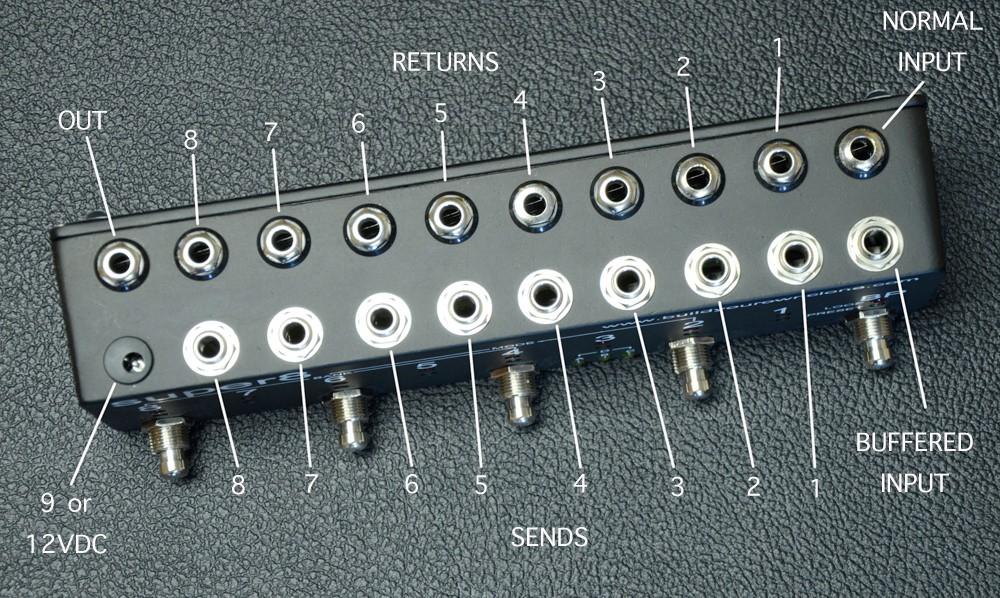
27 Operating Overview NOTE: The example below has been painted and screen printed. Your enclosure will not look like this if you ordered a kit with a bare enclosure.
28
29 IMPORTANT!!!! Because of space contraints, you need to use patch cables that have straight plugs, or you need to use cables that have a small right angle plug, such as George L, Lava, Evidence, Chandler, or other brands that use a similar solderless right angle plug. A cheaper alternative would be to use plastic molded right angle cables. But you cannot use the typical ALL right angle plugs from Switchcraft, Neutrik, Amphenol, etc. You also cannot use ALL pancake style plugs. We put emphasis on the word ALL because you can use some of these style plugs, but how many you can use and where you can use them depends on how much room the neighboring plugs are taking up and what style pedal board you are using. POWER SUPPLY: You can use either 9VDC or 12VDC. We recommend using a supply with at least 300mA of current, but you could use a 200mA supply (see notes about current draw). Use a standard 2.1mm negative tip plug. CURRENT DRAW: 225mA maximum. 25mA minimum. The super8 requires 25mA when all loops are in bypass. Each loop you turn on requires an additional 25mA. You could get away with using a power supply with only 200mA, just try to avoid turning all 8 loops on at once for more than a few seconds. After all do you really need 8 pedals on all at once? If your super8 seems to be working for the most part, but cuts out and resets when you turn on more than a few loops, this probably means that your power supply does not have enough current. NORMAL INPUT: Plug your instrument into this jack if you do not want a signal buffer at the beginning of your chain BUFFERED INPUT: This input offers an active buffer circuit at the very beginning of the super8 s signal path. BUFFERED vs. NORMAL INPUT: In most cases, you will want to use the normal input. A buffer circuit is usually only needed to help drive signal and/or correct impedance if your signal needs to travel long lengths of cable when you have all your FX in bypass. Since the super8 eliminates this problem, you probably won t need it. When you are using things like distortions, overdrives, or boosts that drive your signal or other effects that have a buffer built into the circuit (which most do) there really is no point to using the buffered input. It really depends on the pedals you have in your signal path. Still, there is a good length of PCB trace that your signal must traverse while in bypass, or you may set up one of your loops with multiple FX pedals in it, so maybe you will notice a benefit to using the buffered input. Just plug into both (one at a time of course) and decide for yourself which sounds best, or if you can hear any difference at all. SENDS: Use these jacks to connect to the inputs of your various FX RETURNS: Use these jacks to connect to the outputs of your various FX MODE: the super8 has two modes loop and preset. Loop mode lets you control each of the 8 loops individually. Preset mode lets you call your programmed loop settings. When the red LOOP MODE STATUS LED is lit, that means you are in LOOP MODE. When the green LOOP MODE STATUS LED is lit, that means you are in PRESET MODE How to CHANGE MODE: Press the 6, 4, and 2 foot switch buttons at the same time and release. How to SELECT LOOPS: First you must be in LOOP MODE. Then press the foot switch button of the loop you want to turn on or off.
30 To turn loops 2, 4, 6, and 8 on or off, simply step on and quickly release the corresponding foot switch button. The relays don t actually switch until you release the button, but if you hold the switch in too long, it will save a preset. To turn loops 1, 3, 5, and 7 on or off, you will need to step on and quickly release two footswitch buttons at the same time. For LOOP1, press BP and 2. For LOOP3, press 2 and 4. For LOOP5, press 4 and 6. For LOOP7, press 6 and 8. How to BYPASS: Simply step on and release the BP footswitch button. This will bypass all loops regardless of what mode you are in. It will also remember what loops you had on last so that if you press the BP button when the super8 is in complete bypass, it will recall your previous settings. It actually has 2 memory banks. It can remember settings for both LOOP MODE and PRESET MODE, so that if you are in LOOP MODE first, press BYPASS, and then go to PRESET MODE, when you come back to LOOP MODE again, you will be in bypass. If you step on BYPASS again, it will turn on all the loops you had on the last time you pressed BP in LOOP MODE. It will do the same if you start out in PRESET MODE. You can also use it as a short term on on the fly memory bank when in LOOP MODE. This is because BP will recall your last settings at bypass any time you press the BP button when all of the loops are already in bypass. So if you turn off all of the loops individually with their respective foot switch buttons, and then press the BP button, it will recall your last setting the last time you pressed BP despite whatever loops you turned on and off in the meantime. How to SELECT BANKS: Press the 4, 6, and 8 foot switch buttons at the same time and release. The yellow BANK STATUS LEDs will tell you which bank you are in. It should be obvious which banks are A, B, and C. You are in bank D when both the bank A and C lights are on. When you are in LOOP MODE, the BANK STATUS lights will tell you which bank you are writing to if you save a preset. When you are in PRESET MODE, the BANK STATUS lights tell you which bank you will be reading your presets from. How to PROGRAM: To program a new preset, you must first be in LOOP MODE. Turn on the loops that you want and bypass the loops that you don t want. Then select the bank you want to program to. Finally, to save a preset, press and hold the foot switch(es) of the corresponding loop number that you want to save the preset under for 3 seconds. When a preset is saved, the green preset LED of the corresponding loop number will begin to blink. You can now release the foot switch. NOTE: You can save a preset while you are in PRESET MODE. This can be useful if you want to save a pre-existing loop to a new address. How to CALL A PRESET: First you must be in PRESET MODE. Select the BANK where the preset you want is saved. The press and quickly release the foot switch(es) of the corresponding loop number of the preset that you want.
31
32 Please visit for any technical support copyright 2014 BYOC, Inc.
Tube Cricket Build Guide
 Tube Cricket Build Guide The Tube Cricket is a small-wattage amp that puts out about 1 watt of audio power. With a 12AU7 tube-preamp and a JRC386 power amp, the Tube Cricket gives you great tone in a compact
Build Your Own Clone Relay Bypass Board Instructions
 Build Your Own Clone Relay Bypass Board Instructions Parts list for the Relay Bypass Board Resistors: 1-2k2/222 (Red/Red/Black/Brown/Brown) 1-10k/103 (Brown/Black/Black/Red/Brown) Capacitors: 2-100n/.1uF/104
Multi-Key v2.4 Multi-Function Amplifier Keying Interface
 Multi-Key v2.4 Multi-Function Amplifier Keying Interface ASSEMBLY & OPERATION INSTRUCTIONS INTRODUCTION The Harbach Electronics, LLC Multi-Key is a multi-function external device designed for the safe
Mal-2 assembly guide v1.0
 Mal-2 assembly guide v.0 SONIC POTIONS Schematic and BOM The BOM can be found on Google Docs Prepare the PCB Separate the PCBs using some pliers. PCB We start with the lower PCB and assemble it beginning
MONO AMPLIFIER KIT ESSENTIAL INFORMATION. Version 2.2 CREATE YOUR OWN SPEAKER DOCK WITH THIS
 ESSENTIAL INFORMATION BUILD INSTRUCTIONS CHECKING YOUR PCB & FAULT-FINDING MECHANICAL DETAILS HOW THE KIT WORKS CREATE YOUR OWN SPEAKER DOCK WITH THIS MONO AMPLIFIER KIT Version 2.2 Build Instructions
Introduction 1. Digital inputs D6 and D7. Battery connects here (red wire to +V, black wire to 0V )
") Introduction 1 Welcome to the magical world of GENIE! The project board is ideal when you want to add intelligence to other design or electronics projects. Simply wire up your inputs and outputs and away
Introduction 1 Welcome to the magical world of GENIE! The project board is ideal when you want to add intelligence to other design or electronics projects. Simply wire up your inputs and outputs and away
Introduction 1. Green status LED, controlled by output signal ST. Sounder, controlled by output signal Q6. Push switch on input D6
 Introduction 1 Welcome to the GENIE microcontroller system! The activity kit allows you to experiment with a wide variety of inputs and outputs... so why not try reading sensors, controlling lights or
Bill of Materials: Super Simple Water Level Control PART NO
 Super Simple Water Level Control PART NO. 2169109 Design a simple water controller in which electrodes are required to sense high and low water levels in a tank. Whenever the water level falls below the
While the parts are already inventoried at the factory, please verify the inventory check as you go:
 Thank you for purchasing the kit for building the WJ9J DTMF controller. After building, you should read the document on operation (WJ9JDTMFControllerV5.pdf) in order to use. This is also in the link in
Introduction 1. Green status LED, controlled by output signal ST
 Introduction 1 Welcome to the magical world of GENIE! The project board is ideal when you want to add intelligence to other design or electronics projects. Simply wire up your inputs and outputs and away
Fixed Audio Output for the K2 Don Wilhelm (W3FPR) & Tom Hammond (NØSS) v August 2009
 & Tom Hammond (NØSS) v August 2009") Fixed Audio Output for the K2 Don Wilhelm (W3FPR) & Tom Hammond (NØSS) v. 2.1 06 August 2009 I have had several requests to provide a fixed audio output from the K2. After looking at the circuits that
Fixed Audio Output for the K2 Don Wilhelm (W3FPR) & Tom Hammond (NØSS) v. 2.1 06 August 2009 I have had several requests to provide a fixed audio output from the K2. After looking at the circuits that
TECHNOLOGY WILL SAVE US: THE LUMIPHONE
 TECHNOLOGY WILL SAVE US: THE LUMIPHONE This is a step-by-step guide to soldering your own Lumiphone. The equipment you should have at your station: goggles, soldering mat, soldering Iron, solder and side
8 PIN PIC PROGRAMMABLE BOARD (DEVELOPMENT BOARD & PROJECT BOARD)
") ESSENTIAL INFORMATION BUILD INSTRUCTIONS CHECKING YOUR PCB & FAULT-FINDING MECHANICAL DETAILS HOW THE KIT WORKS LEARN ABOUT PROGRAMMING WITH THIS 8 PIN PIC PROGRAMMABLE BOARD (DEVELOPMENT BOARD & PROJECT
ESSENTIAL INFORMATION BUILD INSTRUCTIONS CHECKING YOUR PCB & FAULT-FINDING MECHANICAL DETAILS HOW THE KIT WORKS LEARN ABOUT PROGRAMMING WITH THIS 8 PIN PIC PROGRAMMABLE BOARD (DEVELOPMENT BOARD & PROJECT
DIY KIT MHZ 8-DIGIT FREQUENCY METER
 This kit is a stand-alone frequency meter capable of measuring repetitive signals up to a frequency of 50MHz. It has two frequency ranges (15 and 50 MHz) as well as two sampling rates (0.1 and 1 second).
N3ZI Digital Dial Manual For kit with Serial LCD Rev 3.04 Aug 2012
 N3ZI Digital Dial Manual For kit with Serial LCD Rev 3.04 Aug 2012 Kit properly assembled and configured for Standard Serial LCD (LCD Not yet connected) Kit Components Item Qty Designator Part Color/Marking
Main PCB (The small one)
") Thanks for choosing our kits! This manual is written taking with the problems that we usually find in our workshops in mind. Also the order is meant to make assembly as easy as possible. Some steps are
Thanks for choosing our kits! This manual is written taking with the problems that we usually find in our workshops in mind. Also the order is meant to make assembly as easy as possible. Some steps are
Lab 7: Soldering - Traffic Light Controller ReadMeFirst
 Lab 7: Soldering - Traffic Light Controller ReadMeFirst Lab Summary The two-way traffic light controller provides you with a quick project to learn basic soldering skills. Grading for the project has been
ELECTRONIC GAME KIT ESSENTIAL INFORMATION. Version 2.0 BUILD YOUR OWN MEMORY & REACTIONS
 ESSENTIAL INFORMATION BUILD INSTRUCTIONS CHECKING YOUR PCB & FAULT-FINDING MECHANICAL DETAILS HOW THE KIT WORKS BUILD YOUR OWN MEMORY & REACTIONS ELECTRONIC GAME KIT Version 2.0 Build Instructions Before
Documentation VFD clock 8 a clock
 Documentation VFD clock 8 a clock This documentation is protected by our copyright. It must not be used for commercial purposes. Congratulations on your purchase of your VFD clock. To guarantee success
Lab 7: Soldering - Traffic Light Controller ReadMeFirst
 Lab 7: Soldering - Traffic Light Controller ReadMeFirst Lab Summary The two way traffic light controller provides you with a quick project to learn basic soldering skills. Grading for the project has been
MAIN PCB (The small one) OPEN MAIN BOARD BAG A
 OPEN MAIN BOARD BAG A") THANKS FOR CHOOSING ONE OF OUR KITS! This manual has been written taking into account the common issues that we often find people experience in our workshops. The order in which the components are placed
THANKS FOR CHOOSING ONE OF OUR KITS! This manual has been written taking into account the common issues that we often find people experience in our workshops. The order in which the components are placed
NewScope-7A Operating Manual
 2016 SIMMCONN Labs, LLC All rights reserved NewScope-7A Operating Manual Preliminary May 13, 2017 NewScope-7A Operating Manual 1 Introduction... 3 1.1 Kit compatibility... 3 2 Initial Inspection... 3 3
COLOUR CHANGING USB LAMP KIT
 TEACHING RESOURCES SCHEMES OF WORK DEVELOPING A SPECIFICATION COMPONENT FACTSHEETS HOW TO SOLDER GUIDE SEE AMAZING LIGHTING EFFECTS WITH THIS COLOUR CHANGING USB LAMP KIT Version 2.1 Index of Sheets TEACHING
Galilean Moons. dual amplitude transmutator. DIY ASSEMBLY MANUAL v1.02
 Galilean Moons dual amplitude transmutator DIY ASSEMBLY MANUAL v1.02 Contents Contents... 2 Introduction... 3 Eurorack Kit Assembly... 4 Resistors... 4 IC Sockets... 5 Ceramic/Film Capacitors... 5 Transistors
N3ZI Digital Dial Manual For kit with Backlit LCD Rev 4.00 Jan 2013 PCB
 N3ZI Digital Dial Manual For kit with Backlit LCD Rev 4.00 Jan 2013 PCB Kit Components Item Qty Designator Part Color/Marking PCB 1 LCD Display 1 LCD 1602 Volt Regulator 1 U1 78L05, Black TO-92 Prescaler
Total solder points: 123 Difficulty level: beginner 1. advanced AUDIO ANALYZER K8098. audio gea Give your. . high-tech ILLUSTRATED ASSEMBLY MANUAL
 Total solder points: 123 Difficulty level: beginner 1 2 3 4 5 advanced AUDIO ANALYZER K8098 ra audio gea Give your. look high-tech ILLUSTRATED ASSEMBLY MANUAL H8098IP-1 Features & Specifications Features
Scale Track System. 21 Century y Signal System 2-Rail Manual
 Scale Track System st 21 Century y Signal System 2-Rail Manual TABLE OF CONTENTS Introduction...2-3 Road Signal Board Diagram and Definitions...4-6 Tips for Handling the Circuit Board...6 2-Rail Detector
Christmas LED Snowflake Project
 Christmas LED Snowflake Project Version 1.1 (01/12/2008) The snowflake is a follow-on from my Christmas star project from a few years ago. This year I decided to make a display using only white LEDs, shaped
DEM 9ULNACK 3.4 GHz. PHEMT LNA amplifier complete kit assembly guide
 DEM 9ULNACK 3.4 GHz. PHEMT LNA amplifier complete kit assembly guide SPECIFICATIONS Noise Figure: < 0.8 db Gain: > 15 db Frequency Range: 3400-3500 MHz Input Voltage: 7-16 VDC Description: The 9ULNACK
TKEY-K16. Touch CW automatic electronic keyer. (No moving parts no contacts) Assembly manual. Last review: March 15, 2018
 Assembly manual. Last review: March 15, 2018") TKEY-K16 Touch CW automatic electronic keyer (No moving parts no contacts) Assembly manual Last review: March 15, 2018 Commands and use manual of the K16 and Updates and news: www.ea3gcy.com Thanks for
TKEY-K16 Touch CW automatic electronic keyer (No moving parts no contacts) Assembly manual Last review: March 15, 2018 Commands and use manual of the K16 and Updates and news: www.ea3gcy.com Thanks for
Building the BX24-AHT
 Building the BX24-AHT file:///f /LASER/build-it.htm (1 of 8) [03/04/2002 5:21:52 PM] file:///f /LASER/build-it.htm (2 of 8) [03/04/2002 5:21:52 PM] Tips & Tricks Use a 25W or smaller soldering iron with
ANTUMBRA FADE MANUAL
 ANTUMBRA FADE MANUAL TABLE OF CONTENTS 01. INSTALLATION 4 02. BACK 5 03. FRONT 6 04. USE 7 05. LINK 8 06. BILL OF MATERIALS 9 07. BUILD NOTES 10 08. BACK 11 09. FRONT 14 10. MODIFICATION 15 11. FINISHED
ELECTRONIC GAME KIT TEACHING RESOURCES. Version 2.0 BUILD YOUR OWN MEMORY & REACTIONS
 TEACHING RESOURCES SCHEMES OF WORK DEVELOPING A SPECIFICATION COMPONENT FACTSHEETS HOW TO SOLDER GUIDE BUILD YOUR OWN MEMORY & REACTIONS ELECTRONIC GAME KIT Version 2.0 Index of Sheets TEACHING RESOURCES
GUIDE TO ASSEMBLY OF ERICA SYNTHS DELAY MODULE
 If you are reading this, most probably, you are about to build Erica Synths DIY DELAY module. The module is 4mm deep, skiff friendly, has solid mechanical construction and doesn t require wiring. Erica
ADD AN AUDIO MESSAGE TO YOUR PRODUCT WITH THIS RECORD & PLAYBACK KIT
 ADD AN AUDIO MESSAGE TO YOUR PRODUCT WITH THIS RECORD & PLAYBACK KIT BUILD INSTRUCTIONS Before you start take a look at the Printed Circuit Board (PCB). The components go in the side with the writing on
Pelican PL-957. Adding additional Tos Link (Digital Optical) inputs, and / or IR Remote
 inputs, and / or IR Remote") Pelican PL-957 Adding additional Tos Link (Digital Optical) inputs, and / or IR Remote Table of Contents: Background;... 2 Section 1: Adding TosLink receivers... 3 Section 2: Adding Remote Capability...
Pelican PL-957 Adding additional Tos Link (Digital Optical) inputs, and / or IR Remote Table of Contents: Background;... 2 Section 1: Adding TosLink receivers... 3 Section 2: Adding Remote Capability...
Installing The PK-AM keyer and. from Jackson Harbor Press Operating: A Morse code keyer chip with pot speed control
 Installing The PK-AM keyer and from Jackson Harbor Press Operating: A Morse code keyer chip with pot speed control The PK-AM keyer is a modification for the PK-AM kit, it changes the AM transmitter to
Analog Style LED Clock
 Analog Style LED Clock Operation and Assembly Manual For use with PCB Rev 2.1 Copyright 2018 All Rights Reserved. Manual version 2.1c, for use with PCB revision 2.1, Software version 2.0.0. The electronic
DIY Guide - Building Franky v1.1, the SEGA Audio and Videocard for MSX
 DIY Guide - Building Franky v1.1, the SEGA Audio and Videocard for MSX 2015 FRS & MSXpró. Translation by FRS and Supersoniqs. Table of Contents Introduction... 3 Materials needed... 3 Audio volume boost...
Nixie Clock Type Frank 2 Z570M
 Assembly Instructions And User Guide Nixie Clock Type Frank 2 Z570M Software version: 7R PCB Revision: 11 April 09-1 - 1. INTRODUCTION 1.1 About the clock Nixie clock type Frank 2 is a compact design with
Pixie Construction Notes
 Pixie Construction Notes PCB V2a February 4 th 2015 Please note that this document is still currently under revision and we apologise for any errors or omissions. Readers should feel free to e-mail any
MUK REAR PANEL ASSEMBLY ASSEMBLY INSTRUCTIONS
 Rev B. 13 August 2017 ASSEMBLY INSTRUCTIONS The Midnight Ultimate Keyer (MUK) consists of two functional assemblies: Rear Panel containing the interface and power connectors. Front Panel containing the
Industrial Monitor Update Kit
 Industrial Monitor Update Kit (Bulletin Number 6157) Installation Instructions 2 Table of Contents Table of Contents Industrial Monitor Update Kit... 3 Overview... 3 Part 1 - Initial Preparation... 5 Part
DL-1A. RF dummy load - 50Ω 20W. Assembly manual. Last update: May 1, Thank you for constructing the DL-1A dummy load kit
 DL-1A RF dummy load - 50Ω 20W Assembly manual Last update: May 1, 2016 ea3gcy@gmail.com Updates and news at: www.qsl.net/ea3gcy Thank you for constructing the DL-1A dummy load kit Have fun assembling it
Nixie Clock Type Frank 3
 Assembly Instructions And User Guide Nixie Clock Type Frank 3 Software version: 7R PCB Version: 11 April 09-1 - 1. INTRODUCTION 1.1 About the clock Nixie clock type Frank 3 is a compact design with all
VU Meter Buffer DIY Kit
 VU Meter Buffer DIY Kit Warning This document is distributed for educational purposes only. This equipment operates at potentially lethal voltages. Only trained, qualified personnel should operate, maintain,
Nixie Clock Kit IN-12B color LED backlit Operation Manual Nixie Clock Kit IN-12B V6.0 ( All Right Reserved 2015 )
") Nixie Clock Kit IN-B color LED backlit Operation Manual Nixie Clock Kit IN-B V. ( All Right Reserved ) - - Operation Manual IN-B Nixie Clock Power for your Nixie Clock The clock does not include a wall
Nixie Clock Kit IN-B color LED backlit Operation Manual Nixie Clock Kit IN-B V. ( All Right Reserved ) - - Operation Manual IN-B Nixie Clock Power for your Nixie Clock The clock does not include a wall
How To Build Megavolt s Small Buffered JTAG v1.2
 How To Build Megavolt s Small Buffered JTAG v1.2 Abstract A JTAG cable should be considered mandatory equipment for any serious tester. It provides a means to backup the information in the receiver and
ADAT DC Coupling Modifications for Laser Graphic Recording
 Technical Committee ADAT DC Coupling Modifications for Laser Graphic Recording Introduction... 1 ADAT PCB Modifications... 2 Additional ADAT Information... 3 Footnotes... 6 Revision 002, October 1995 ADAT
QUIZ BUZZER KIT TEACHING RESOURCES. Version 2.0 WHO ANSWERED FIRST? FIND OUT WITH THIS
 TEACHING RESOURCES SCHEMES OF WORK DEVELOPING A SPECIFICATION COMPONENT FACTSHEETS HOW TO SOLDER GUIDE WHO ANSWERED FIRST? FIND OUT WITH THIS QUIZ BUZZER KIT Version 2.0 Index of Sheets TEACHING RESOURCES
What is the E560? Connecting to the power supply
 PAGE 1 E560 Deflector Shield DIY Kit www.synthtech.com/euro/e560 What is the E560? The Synthesis Technology E560 is a combination frequency shifter, phaser and ring modulator. The audio is mono in, and
PR-101 STEREO PREAMPLIFIER Phono Preamp ASSEMBLY MANUAL
 PR-101 STEREO PREAMPLIFIER Phono Preamp ASSEMBLY MANUAL 2016 AkitikA LLC All rights reserved Revision 1p18 March 12, 2016 Page 1 of 24 Table of Contents Table of Contents... 2 Table of Figures... 2 Section
Build A Video Switcher
 Build A Video Switcher VIDEOSISTEMAS serviciotecnico@videosistemas.com www.videosistemas.com Reprinted with permission from Electronics Now Magazine September 1997 issue Copyright Gernsback Publications,
Atari PICO Composite Mod Board Installation Instructions:
 Atari PICO Composite Mod Board Installation Instructions: Installation Guide 6 Switch Atari 2600 6 Switch Video Mod Installation Guide Disclaimer: I am not responsible for any damage done to your Atari.
VU-1 VU Meter Kit Volume Unit Meter
 VU-1 VU Meter Kit Volume Unit Meter Simplicity Counts, Detail Matters. No part of this document may be reproduced, either mechanically or electronically, posted online on the Internet, in whole or in part,
Mini-Yack Iambic Keyer
 Mini-Yack Iambic Keyer Assembly Instructions Mini-Yack is a "bare bones" Iambic keyer for embedding into QRP and home brew equipment. The keyer has the following features: Keying from 1-50WPM YACK memory
MAKE AN RGB CONTROL KNOB.
 MAKE AN RGB CONTROL KNOB. This is a knob based colour changing controller that uses a custom programmed microcontroller to pack a lot of features into a small affordable kit. The module can drive up to
7 SEGMENT LED DISPLAY KIT
 ESSENTIAL INFORMATION BUILD INSTRUCTIONS CHECKING YOUR PCB & FAULT-FINDING MECHANICAL DETAILS HOW THE KIT WORKS CREATE YOUR OWN SCORE BOARD WITH THIS 7 SEGMENT LED DISPLAY KIT Version 2.0 Which pages of
Color Organ Triple Deluxe II.
 http://wwwinstructablescom/id/color-organ-triple-deluxe-ii/ Food Living Outside Play Technology Workshop Color Organ Triple Deluxe II by ledartist on January 13, 2013 Table of Contents Color Organ Triple
REPLAY JUNIOR. True high voltage tube delay. V 1.1 (27-August-2012) Operations Manual
 Operations Manual") REPLAY JUNIOR True high voltage tube delay V 1.1 (27-August-2012) Operations Manual Plush division of Fuchs Audio Technology 407 Getty Ave Clifton, NJ 07015 (973) 772-4420 (fax) 973-772-4460 Website: www.plush-pedals.com
REPLAY JUNIOR True high voltage tube delay V 1.1 (27-August-2012) Operations Manual Plush division of Fuchs Audio Technology 407 Getty Ave Clifton, NJ 07015 (973) 772-4420 (fax) 973-772-4460 Website: www.plush-pedals.com
Trace Elliot Transit B Bass Instrument Preamp
 Trace Elliot Transit B Bass Instrument Preamp Owner s Manual FCC Compliancy Statement This device complies with Part 15 of the FCC rules. Operation is subject to the following two conditions: (1) this
MACH3 LaserAce Installation Manual Revision 1. MACH3 LaserAce Installation Manual
 WWW.LASERARCADE.COM MACH3 LaserAce Installation Manual Revision 1 MACH3 LaserAce Installation Manual Table of Contents Introduction...1 Parts supplied with MACH3 FNI...1 Why the MACH3 FNI is required...2
XTAL Bank DDS Version 0.02 Sept Preliminary, highly likely to contain numerous errors
 XTAL Bank DDS Version 002 Sept 7 2012 Preliminary, highly likely to contain numerous errors The photo above shows the fully assembled Xtal Bank DDS with 2 DDS modules installed (The kit is normally only
OPERATION NOTES FOR PSIDEX AUDIO PGP-1A PRE-AMPLIFIER DESCRIPTION INSTALLATION
 OPERATION NOTES FOR PSIDEX AUDIO PGP-1A PRE-AMPLIFIER DESCRIPTION The Psidex Audio Laboratory PGP- 1A is a vacuum tube based microphone preamp and program line amplifier designed to provide solid, robust
LED Backlight for Technics amplifiers
 LED Backlight for Technics amplifiers Technics SE-A900S Technics SE-A900SM2 Technics SE-A909S Technics SE-A1000 Technics SE-A1000M2 Technics SE-A1010 Rev. 1.2 B Description The LED module is designed to
Summit Systems Sound Board Modification
 Summit Systems Sound Board Modification The Summit slots fitted with the music feature play two sounds; one when the coin is inserted, and the other that plays as winning coins pass through the hopper
Nutube.US. 6P1 Evaluation Board. User Manual
 Nutube.US 6P1 Evaluation Board User Manual Introduction The 6P1 Evaluation Board (EVB) is a vehicle for testing and evaluating the Korg Nutube 6P1 dual triode in audio circuits. This product is designed
MOD028 GLOCKENSPIEL TECHNO-MUSIC-OLOGY
 MOD028 GLOCKENSPIEL TECHNO-MUSIC-OLOGY MOD028 - Techno-music-ology Kit Contents Motor Controller PCBs 14 220R (red red brown gold) resistors 2 330R (orange orange brown gold) resistors 16 1N4001 diodes
Parts Checklist - Please note there is no resistor R3. Diodes, LED and transistors are polarized see construction stages
 Xtal Check Kit build Read me first! -------- UPDATED GUIDE------ September 12, 2018--------- The following steps are designed to get your Xtal check kit built and operational. This is a good beginner s
DLP600M 6+1 Relay Module for Heating and Cooling Plants
 Product Sheet TH6.25 Thermostat Type DLP600M DLP600M 6+1 Relay Module for Heating and Cooling Plants The DLP 600 M is a relay module for activation of loads (namely thermal actuators or circulators) in
LP-PAN Preamp Kit Assembly Manual
 LP-PAN Preamp Kit Assembly Manual December 2010 TelePost Incorporated Rev. A9 1 Table of Contents Introduction... 2 Specifications... 3 Parts List... 4 Assembly... 5 Checkout / Schematic... 9 Introduction
QTI Line Follower AppKit for the Boe-Bot (#28108)
") Web Site: www.parallax.com Forums: forums.parallax.com Sales: sales@parallax.com Technical: support@parallax.com Office: (916) 624-8333 Fax: (916) 624-8003 Sales: (888) 512-1024 Tech Support: (888) 997-8267
Web Site: www.parallax.com Forums: forums.parallax.com Sales: sales@parallax.com Technical: support@parallax.com Office: (916) 624-8333 Fax: (916) 624-8003 Sales: (888) 512-1024 Tech Support: (888) 997-8267
DLP200M 2 Relay Module for Heating and Cooling Plants
 Product Sheet TH6.24 Thermostat Type DLP200M DLP200M 2 Relay Module for Heating and Cooling Plants The DLP 200 M is a relay module for activation of loads (namely thermal actuators or circulators) in wireless
2000 Series Weather Stations Analog Temperature / RH Sensor Upgrade Kit PRODUCT MANUAL KIT # 3613WDU
 2000 Series Weather Stations Analog Temperature / RH Sensor Upgrade Kit PRODUCT MANUAL KIT # 3613WDU 1 The 3613WDU Analog Temperature / RH Sensor Upgrade Kit is used to upgrade Watchdog 2000 Series Weather
Obtained from Omarshauntedtrail.com
 http://www.cindybob.com/halloween/ledlighting/ledspotlights/ Introduction In our 2005 haunt providing 120V AC power to the various lights and props requiring it became a fairly large problem. Extension
TR-Plus T/R Switch Assembly and Operation Manual. Introduction
 TR-Plus T/R Switch Assembly and Operation Manual Revised: 7 February 2015 2015 Tucson Amateur Packet Radio Corporation Introduction The TAPR TR-Plus is a transmit/receive ( T/R ) switch that connects a
RGB 5050 PixelControl LED Super Flat Rope Part Numbers: PSFR-RGB-W-20
 11235 West Bernardo Court, Suite 102 San Diego, CA 92127 888-880-1880 Fax: 707-281-0567 EnvironmentalLights.com RGB 5050 PixelControl LED Super Flat Rope Part Numbers: PSFR-RGB-W-20 PixelControl LED Super
Atari 400/800 Super Color CPU Card
 Installation Instructions Atari 400/800 Super Color CPU Card Date: 2017, May 3 rd, version 1.1 Author: Jürgen van Radecke (tfhh) Introduction Hi, Thank you for your purchase of a Super Colour CPU Card!
RF Nomad Semi-SMT. SDIY Kit Assembly Manual
 RF Nomad Semi-SMT Introduction Thanks for purchasing the RF Nomad SDIY kit from Evaton Technologies! The RF Nomad SDIY kit is a voltage-controlled shortwave radio receiver in Eurorack format. The RF Nomad
"Sophisticated Model Railroad Electronics"
 LOGIC RAIL TM "Sophisticated Model Railroad Electronics" TECHNOLOGIES 21175 Tomball Pkwy Phone: (281) 251-5813 Suite 287 email: info@logicrailtech.com Houston, TX 77070 http://www.logicrailtech.com Block
Hamcrafters K44 CW Keyboard/Reader Kit Assembly Guide Revision A.0
 Introduction Figure 1 Assembled K44 This document will describe how to assemble and test a K44 Kit. The assembly requires reasonably good soldering skill. Before you start working, gather the following
GEKCO SUBCARRIER REFERENCE OSCILLATOR MODEL SRO10 OPERATION/SERVICE MANUAL
 GEKCO MODEL SRO10 SUBCARRIER REFERENCE OSCILLATOR OPERATION/SERVICE MANUAL GEKCO Labs PO Box 642 Issaquah, WA 98027 (425) 392-0638 P/N 595-431 REV 5/98 Copyright c 1998 GEKCO Labs All Rights Reserved Printed
Total solder points: 117 Difficulty level: beginner advanced. RGB Controller K8088 ILLUSTRATED ASSEMBLY MANUAL
 Total solder points: 117 Difficulty level: beginner 1 2 3 4 5 advanced RGB Controller K8088 Control incandescent bulbs, LEDs, common anode led strips, etc... ILLUSTRATED ASSEMBLY MANUAL H8088IP-1 Features
RSL MusicPower Plug-In Installation Manual For Naim NAC 72 Preamp
 RSL MusicPower Plug-In Installation Manual For Naim NAC 72 Preamp (Updated to reflect the adjustable gain output boards Z200V) www.ryansoundlab.com RSL MusicPower Plug-In Installation Manual for Naim NAC
OPERATIONAL MANUAL EMZS CH Speaker Zone Selector. Version 1.6
 OPERATIONAL MANUAL EMZS-8012 12CH Speaker Zone Selector Version 1.6 1 Product Overview The EMZS-8012 is a 1U rack-mounting unit, provide 12 channel direct zone switching for single source public address
Category Index. Category Page# Category Page# Category Page# Audio Audio XLR Connecter
 Category Index Category Page# Category Page# Category Page# 98 Adapters Adapter Accessories... 6-29 Adapter Kit, Coaxial Cable... 17-20 Banana Jack and Plug... 33-43 [see separate Banana Plugs & Jacks
Nixie Clock Type Quattro'
 Assembly Instructions And User Guide Nixie Clock Type Quattro' - 1 - Issue Number Date REVISION HISTORY 2 8 Sept 2012 Errors corrected 1 27 July 2012 New document Reason for Issue - 2 - 1.1 Nixie Quattro
Azatrax Model Railroad Track Signal Control - Single Track
 Installation Guide Azatrax Model Railroad Track Signal Control - Single Track TS2 What it is: The TS2 operates one or two trackside block signals (one in each direction) on one track to simulate the block
Assembly Instructions And User Guide. Nixie FunKlock. FunKlock Issue 4 (1 February 2017)
") Assembly Instructions And User Guide Nixie FunKlock - 1 - Issue Number Date REVISION HISTORY 4 1 February 2017 New diode for D2 3 27 December 2013 C7 / C8 error page 15 2 7 November 2013 Errors corrected
Assembly Instructions And User Guide Nixie FunKlock - 1 - Issue Number Date REVISION HISTORY 4 1 February 2017 New diode for D2 3 27 December 2013 C7 / C8 error page 15 2 7 November 2013 Errors corrected
16 Stage Bi-Directional LED Sequencer
 16 Stage Bi-Directional LED Sequencer The bi-directional sequencer uses a 4 bit binary up/down counter (CD4516) and two "1 of 8 line decoders" (74HC138 or 74HCT138) to generate the popular "Night Rider"
Physics 123 Hints and Tips
 Physics 123 Hints and Tips Solderless Breadboards All of the analog labs and most of the digital labs will be built on the Proto-Board solderless breadboards. These provide three solderless breadboard
AXE101 PICAXE-08M2 Cyberpet Kit
 AXE101 PICAXE-08M2 Cyberpet Kit The Cyberpet project uses a PICAXE-08M2 microcontroller with two LEDs as the pets eyes and a piezo sounder as a voice for the pet. The project also uses a switch so that
Summit Audio Model TLA-50 Tube Leveling Amplifier
 Summit Audio Model TLA-50 Tube Leveling Amplifier ATTACK FAST SLOW MEDIUM 3 4 5 6 7 TUBE LEVELER 40 60 80 100 VU 3 4 5 6 TLA-50 7 FAST SLOW RELEASE OUTPUT RED. METER 2 1 0 10 GAIN 9 8 7 5 3 1 0 1 2 +3
Sega MegaDrive 1 RGB Bypass Installation Guide Rev 1.1
 Sega MegaDrive 1 RGB Bypass Installation Guide Rev 1.1 This step by step guide describes the Installation of the open source Voultar RGB Bypass Amplifier board for the original SEGA MegaDrive/Genesis 1.
General Wiring and Installation Guidelines. Typical Mounting Installations Electrical Connections General Guidelines Common Questions & Answers
 General Wiring and Installation Guidelines Typical Mounting Installations Electrical Connections General Guidelines Common Questions & Answers Congratulations on your purchase of a Dynapar brand encoder.
Etherwave Plus Field Upgrade Instructions
 Etherwave Plus Field Upgrade Instructions The Etherwave Plus Field Upgrade is an advanced project for upgrading a standard Moog Music Etherwave theremin to the Etherwave Plus. The new features of the Etherwave
Building a MidiBox LCD Cable
 Building a MidiBox LCD Cable By Jim Henry, 3-Apr-2004 An LCD panel may be connected to the Core module by a 16 conductor flat ribbon cable. A 16 pin insulation displacement connector (IDC) terminates one
HS-509 VIBRATION TRIP MODULE
 HS-509 VIBRATION TRIP MODULE 1. Overview The HS-509 is a configurable trip amplifier capable of accepting a 4-20mA signal from a HS-420 sensor and providing two trip action relay outputs along with an
H2633IP-1 RELAY CARD K2633
 H2633IP-1 RELAY CARD K2633 Control up to 4 high-power circuits from a low-power drive circuit. Features & Specifications The connection of a few relays to the outputs of an electronic circuit might be
This Unit may form part of a National Qualification Group Award or may be offered on a free standing basis.
 National Unit Specification: general information CODE F5JJ 11 SUMMARY The Unit is intended for candidates with little or no prior knowledge of Analogue or Digital Electronic Circuits. It provides an opportunity