Digital Circuits. Innovation Fellows Program
|
|
|
- Colleen Dennis
- 6 years ago
- Views:
Transcription

1 Innovation Fellows Program Digital Circuits, Department of Biomedical Engineering, University of Minnesota
2 Topics Digital Electronics TTL and CMOS Logic National Instrument s Multisim (SPICE) and Ultiboard Software Prototyping with Breadboards Boolean Logic CMOS and TTL IC Packaging and Pinouts Various Devices and Circuits Schmitt triggers Contact debouncing Simulation and elimination of noise; voltage summing Leading edge detection Counters and 7-segment display Drivers for LEDs, lamps and relays Ad and DA Converters


3 Dawn of the Digital Age Slide Rule - 17 th Century to ~ Home Computer 1969 (Steven Saliterman) Intel 8080 Microprocessor 1974 Altair First Commercial Personal Computer 1975 (Ed Roberts)
 Point-contact")
.")
, & Intel")
4 Microelectronics Revolution Triode tube 1915 (Langmuir) Point-contact transistor 1947, Bell Labs (Brattain and Bardeen). Junction transistor 1948 (Shockley), IC 1958 (Kibly and Noyce), & Intel Pentium Microprocessor 10 8 Transistors!


.")
5 From Molten Silicon to IC Chips Molten silicon - Czochralski puller technique Silicon wafer diced into integrated circuits (DIP and SMD). Single crystal silicon boule
6 Digital Logic IC Families TTL - Transistor-Transistor Logic Versions Standard, high speed, low power and Schottky - e.g. 74LS00 series ECL - Emitter Coupled Logic CMOS - Complementary Metal Oxide Semiconductor Logic e.g. 4000B and 74HC00 series.
. Buffers have a fan-out of ~30. 5 VDC power supply typical. Unconnected inputs tend to pull themselves up to a positive value. Current sinking logic.")
7 TTL Logic Positive logic 1 is positive (high) and 0 is ground or below 0.8 volt (low). The outputs can directly drive up to ten other TTL logic inputs (fanout of ten). However, only one input is allowed (fan-in of one). Buffers have a fan-out of ~30. 5 VDC power supply typical. Unconnected inputs tend to pull themselves up to a positive value. Current sinking logic. The output-low state is capable of sinking 16 ma. The output-high state is above 2.4 volts, typically around 3.3 volts below the supply voltage. Require a despiking capacitor (0.1 to.01µf) every 1 to 4 ICs (if separated by no more than 3 ) to eliminate spikes caused by internal transistor switching.
.")
8 CMOS Logic Low cost. Inputs are open circuits and easy to drive. Almost no power supply current needed except during input logic changes. Logic changes half-way up the power supply voltage, giving good noise immunity (at least better than TTL). Wide range of power supply voltages, from 3 to 15 Vdc The unloaded output logic swings the full range of the power supply. CMOS circuits create little noise of their own. CMOS circuits pass along less noise.

9 Design with NI Multisim
10 CMOS Packages & Pins Lancaster, D. and Berlin, H.M. CMOS Cookbook. H.W. Sams, Indianapolis, IN (1988)


11 Inverter 74HC04 Notice the output is inverse to the input. Input High Low Output Low High
12 Available Logic Gates in the 74HC04 Lancaster, D. and Berlin, H.M. CMOS Cookbook. H.W. Sams, Indianapolis, IN (1988)
13 NAND 74HC00 Input 1 Input 2 Output If either or both inputs are low the output will be high.

14 Available Logic Gates in the 74HC00 In addition to this NAND gate, there are many different types and combinations of Boolean logic gates to select from. These include AND, OR, NOR, Exclusive OR & NOR and others. Lancaster, D. and Berlin, H.M. CMOS Cookbook. H.W. Sams, Indianapolis, IN (1988)


15 Flip-Flop 74HC74 QQ QQ Notice the divide by 2 of frequency. The information presented to the D input goes on to the QQ output whenever the clock input changes from a low to a high level. If D is high, on clocking, QQ goes high and QQ goes low. If D is low, on clocking, QQ goes low and QQ goes high.
16 4 Bit Binary Counter with Buffer Drivers Place 2 3 =8 2 2 =4 2 1 =2 2 0 =1

17 Available Logic Gates in the 74HC74 In addition to this D-Flip-Flop, there are also JK Flip-Flops Lancaster, D. and Berlin, H.M. CMOS Cookbook. H.W. Sams, Indianapolis, IN (1988)

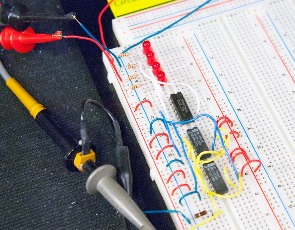
18 Counter on Breadboard

19 Tri-State Logic 74HC126
20 Available Logic Gates in the 74HC126 Lancaster, D. and Berlin, H.M. CMOS Cookbook. H.W. Sams, Indianapolis, IN (1988)

21 Schmitt Trigger 74C14


22 Switch Contact Noise Thresholds are ~ 1.35 V for Low and 3.15 V for High Mechanical contact noise can cause multiple pulses to occur the first 100 µs or so. In this example, three pulses would be generated.

23 Contact Debouncer Schmitt Trigger Output Input Switch Off & On

24 Creating Noise with Voltage Summing Voltage Summing Voltage Inverter

25 Noise Eliminator Schmitt Trigger 4093B Summer Input Output Voltage Follower

26 Leading Edge Detector Schmitt Trigger Debounced button pushes Single pulse with each positive edge
27 Available Logic Gates in the 74HC14 & 4093B Lancaster, D. and Berlin, H.M. CMOS Cookbook. H.W. Sams, Indianapolis, IN (1988)

28 One-and-only One Synchronized Pulse Clock Button Output is a synchronized pulse with the clock, while the button push is not.

29 Driving LEDs 4049B Current sourcing. Current sinking. RR 1 oooo 2 = VV FF II FF The 4049 Inverter- Buffer can source or sink sufficient current to light the LED directly. For other CMOS logic you need to have a transistor. Push Button Debounce Certain devices, like counters, may have built in LED drivers.
30 Available Logic Gates in the 4049B Lancaster, D. and Berlin, H.M. CMOS Cookbook. H.W. Sams, Indianapolis, IN (1988)
31 Decade Stepper 4017B

32 Available Logic Gates in the 4017B In addition to this divide-by -10 counter, there are many other types, some with multiple stages; different bases decade, binary, and octal; directions - up-down; and ripple vs. synchronous. Lancaster, D. and Berlin, H.M. CMOS Cookbook. H.W. Sams, Indianapolis, IN (1988)
33 Decade Counter 4518B & 4511B A 7-segment common cathode display: Display current limiting resistors 7-segment latch & drivers Dual synchronous divide by ten counter
34 Available Logic Gates in the 4518B & 4511B Lancaster, D. and Berlin, H.M. CMOS Cookbook. H.W. Sams, Indianapolis, IN (1988)

. 5")
35 Lamp Driver with Transistor Lamp is rated 5 V and power of 200 mw. Required current: PPPPPPPPPP WW = II 2 RR = VVVV II = PPPPPPPPPP WW 200 mmmm = = 40 mmmm VV The 2N2222 is a general purpose medium power amplifier and switch, for I C of up to 500 ma (max. 1 A). 5
.")
36 MOSFET Relay Driver with Transient Suppression MOSFET is a transconductance device (base current is negligible, base voltage controls collector current). The MOSFET allows for higher collector current than the BJT.
37 Analog to Digital Converters Analog to Digital Converters (ADC) Convert an analog signal such as voltage, into a digital signal. Resolution is the number of discrete values the converter can produce over the range of the analog signal. For example, an 8-bit encoder can decode an analog value to 2 8, or 256 different values. Sampling rate is subject to the Nyquist-Shannon sampling theorem. In simple terms, you must sample minimally at a rate twice that of the frequency in order to reproduce the original analog signal.
38 Digital to Analog Converters Digital to Analog Converters (DAC) Convert digital data into an analog signal, such as voltage or current. Commonly used to reproduce music from CD to amplifiers, speakers and headphones. The Arduino pins can be configured for ADC and DAC. Dedicated ADC/DAC chips are available from a number of manufacturers.
39 Summary Digital Electronics TTL and CMOS Logic Designing with NI Multisim (SPICE) and Ultiboard Software Prototyping with Breadboards Boolean Logic CMOS and TTL IC Packaging and Pinouts Various Devices and Circuits Schmitt triggers Contact debouncing Simulation and elimination of noise; voltage summing Leading edge detection Counters and 7-segment display Drivers for LEDs, lamps and relays AD and DA Converters
Digital Circuits Part 1 Logic Gates
 Introductory Medical Device Prototyping Digital Circuits Part 1 Logic Gates, http://saliterman.umn.edu/ Department of Biomedical Engineering, University of Minnesota Topics Digital Electronics CMOS Logic
Topics. Microelectronics Revolution. Digital Circuits Part 1 Logic Gates. Introductory Medical Device Prototyping
 Introductory Medical Device Prototyping Digital Circuits Part 1 Logic Gates, http://saliterman.umn.edu/ Department of Biomedical Engineering, University of Minnesota Topics Digital Electronics CMOS Logic
PHYSICS 5620 LAB 9 Basic Digital Circuits and Flip-Flops
 PHYSICS 5620 LAB 9 Basic Digital Circuits and Flip-Flops Objective Construct a two-bit binary decoder. Study multiplexers (MUX) and demultiplexers (DEMUX). Construct an RS flip-flop from discrete gates.
B. Sc. III Semester (Electronics) - ( ) Digital Electronics-II) BE-301 MODEL ANSWER (AS-2791)
 - ( ) Digital Electronics-II) BE-301 MODEL ANSWER (AS-2791)") B. Sc. III Semester (Electronics) - (2013-14) Digital Electronics-II) BE-301 MODEL ANSWER (AS-2791) Section-[A] i. (B) ii. (A) iii. (D) iv. (C) v. (C) vi. (C) vii. (D) viii. (B) Ans-(ix): In JK flip flop
B. Sc. III Semester (Electronics) - (2013-14) Digital Electronics-II) BE-301 MODEL ANSWER (AS-2791) Section-[A] i. (B) ii. (A) iii. (D) iv. (C) v. (C) vi. (C) vii. (D) viii. (B) Ans-(ix): In JK flip flop
DIGITAL CIRCUIT COMBINATORIAL LOGIC
 DIGITAL CIRCUIT COMBINATORIAL LOGIC Logic levels: one zero true false high low CMOS logic levels: 1 => 0.7 V DD 0.4 V DD = noise margin 0 =< 0.3 V DD Positive logic: high = 1 = true low = 0 = false Negative
Physics 323. Experiment # 10 - Digital Circuits
 Physics 323 Experiment # 10 - Digital Circuits Purpose This is a brief introduction to digital (logic) circuits using both combinational and sequential logic. The basic building blocks will be the Transistor
EXPERIMENT #6 DIGITAL BASICS
 EXPERIMENT #6 DIGITL SICS Digital electronics is based on the binary number system. Instead of having signals which can vary continuously as in analog circuits, digital signals are characterized by only
MODULAR DIGITAL ELECTRONICS TRAINING SYSTEM
 MODULAR DIGITAL ELECTRONICS TRAINING SYSTEM MDETS UCTECH's Modular Digital Electronics Training System is a modular course covering the fundamentals, concepts, theory and applications of digital electronics.
[2 credit course- 3 hours per week]
![[2 credit course- 3 hours per week]](/thumbs/94/121292011.jpg "[2 credit course- 3 hours per week]") Syllabus of Applied Electronics for F Y B Sc Semester- 1 (With effect from June 2012) PAPER I: Components and Devices [2 credit course- 3 hours per week] Unit- I : CIRCUIT THEORY [10 Hrs] Introduction;
Syllabus of Applied Electronics for F Y B Sc Semester- 1 (With effect from June 2012) PAPER I: Components and Devices [2 credit course- 3 hours per week] Unit- I : CIRCUIT THEORY [10 Hrs] Introduction;
WINTER 15 EXAMINATION Model Answer
 Important Instructions to examiners: 1) The answers should be examined by key words and not as word-to-word as given in the model answer scheme. 2) The model answer and the answer written by candidate
1 Hour Sample Test Papers: Sample Test Paper 1. Roll No.
 6.1.2 Sample Test Papers: Sample Test Paper 1 Roll No. Institute Name: Course Code: EJ/EN/ET/EX/EV/IC/IE/IS/MU/DE/ED/ET/IU Subject: Principles of Digital Techniques Marks: 25 1 Hour 1. All questions are
Computer Systems Architecture
 Computer Systems Architecture Fundamentals Of Digital Logic 1 Our Goal Understand Fundamentals and basics Concepts How computers work at the lowest level Avoid whenever possible Complexity Implementation
Massachusetts Institute of Technology Department of Electrical Engineering and Computer Science
 Massachusetts Institute of Technology Department of Electrical Engineering and Computer Science 6.111 - Introductory Digital Systems Laboratory Project Resources Project resources are allocated on a per
Digital Electronic Circuits and Systems
 Digital Electronic Circuits and Systems Macmillan Basis Books in Electronics General Editor: Noel M. Morris, Principal Lecturer, North Staffordshire Polytechnic LINEAR ELECTRONIC CIRCUITS AND SYSTEMS:
WINTER 14 EXAMINATION
 Subject Code: 17320 WINTER 14 EXAMINATION Model Answer Important Instructions to examiners: 1) The answers should be examined by key words and not as word-to-word as given in the model answer scheme. 2)
Laboratory 10. Required Components: Objectives. Introduction. Digital Circuits - Logic and Latching (modified from lab text by Alciatore)
") Laboratory 10 Digital Circuits - Logic and Latching (modified from lab text by Alciatore) Required Components: 1x 330 resistor 4x 1k resistor 2x 0.F capacitor 1x 2N3904 small signal transistor 1x LED 1x
Laboratory 10 Digital Circuits - Logic and Latching (modified from lab text by Alciatore) Required Components: 1x 330 resistor 4x 1k resistor 2x 0.F capacitor 1x 2N3904 small signal transistor 1x LED 1x
Digital Circuits I and II Nov. 17, 1999
 Physics 623 Digital Circuits I and II Nov. 17, 1999 Digital Circuits I 1 Purpose To introduce the basic principles of digital circuitry. To understand the small signal response of various gates and circuits
Notes on Digital Circuits
 PHYS 331: Junior Physics Laboratory I Notes on Digital Circuits Digital circuits are collections of devices that perform logical operations on two logical states, represented by voltage levels. Standard
Notes on Digital Circuits
 PHYS 331: Junior Physics Laboratory I Notes on Digital Circuits Digital circuits are collections of devices that perform logical operations on two logical states, represented by voltage levels. Standard
Laboratory 1 - Introduction to Digital Electronics and Lab Equipment (Logic Analyzers, Digital Oscilloscope, and FPGA-based Labkit)
") Massachusetts Institute of Technology Department of Electrical Engineering and Computer Science 6. - Introductory Digital Systems Laboratory (Spring 006) Laboratory - Introduction to Digital Electronics
Massachusetts Institute of Technology Department of Electrical Engineering and Computer Science 6. - Introductory Digital Systems Laboratory (Spring 006) Laboratory - Introduction to Digital Electronics
TYPICAL QUESTIONS & ANSWERS
 DIGITALS ELECTRONICS TYPICAL QUESTIONS & ANSWERS OBJECTIVE TYPE QUESTIONS Each Question carries 2 marks. Choose correct or the best alternative in the following: Q.1 The NAND gate output will be low if
Laboratory 7. Lab 7. Digital Circuits - Logic and Latching
 Laboratory 7 igital Circuits - Logic and Latching Required Components: 1 330 resistor 4 resistor 2 0.1 F capacitor 1 2N3904 small signal transistor 1 LE 1 7408 AN gate IC 1 7474 positive edge triggered
TEST-3 (DIGITAL ELECTRONICS)-(EECTRONIC)
-(EECTRONIC)") 1 TEST-3 (DIGITAL ELECTRONICS)-(EECTRONIC) Q.1 The flip-flip circuit is. a) Unstable b) multistable c) Monostable d) bitable Q.2 A digital counter consists of a group of a) Flip-flop b) half adders c)
1 TEST-3 (DIGITAL ELECTRONICS)-(EECTRONIC) Q.1 The flip-flip circuit is. a) Unstable b) multistable c) Monostable d) bitable Q.2 A digital counter consists of a group of a) Flip-flop b) half adders c)
Digital Principles and Design
 Digital Principles and Design Donald D. Givone University at Buffalo The State University of New York Grauu Boston Burr Ridge, IL Dubuque, IA Madison, Wl New York San Francisco St. Louis Bangkok Bogota
MSCI 222C Fall 2018 Introduction to Electronics
 MSCI 222C Fall 2018 Introduction to Electronics Charles Rubenstein, Ph. D. Professor of Engineering & Information Science Session 9: Mon/Tues 11/05/18 & 11/06/18 (H8,Q7,L7) Take Home Midterm EXAM REVIEW
Music Electronics Finally DeMorgan's Theorem establishes two very important simplifications 3 : Multiplexers
 Music Electronics Finally DeMorgan's Theorem establishes two very important simplifications 3 : ( A B )' = A' + B' ( A + B )' = A' B' Multiplexers A digital multiplexer is a switching element, like a mechanical
Light Emitting Diodes and Digital Circuits I
 LED s and Digital Circuits I. p. 1 Light Emitting Diodes and Digital Circuits I The Light Emitting Diode: The light emitting diode (LED) is used as a probe in the digital experiments below. We begin by
TIME SCHEDULE. MODULE TOPICS PERIODS 1 Number system & Boolean algebra 17 Test I 1 2 Logic families &Combinational logic
 COURSE TITLE : DIGITAL INSTRUMENTS PRINCIPLE COURSE CODE : 3075 COURSE CATEGORY : B PERIODS/WEEK : 4 PERIODS/SEMESTER : 72 CREDITS : 4 TIME SCHEDULE MODULE TOPICS PERIODS 1 Number system & Boolean algebra
Light Emitting Diodes and Digital Circuits I
 LED s and Digital Circuits I. p. 1 Light Emitting Diodes and Digital Circuits I Tasks marked by an asterisk (*) may be carried out before coming to the lab. The Light Emitting Diode: The light emitting
ME 515 Mechatronics. Introduction to Digital Electronics
 ME 55 Mechatronics /5/26 ME 55 Mechatronics Digital Electronics Asanga Ratnaweera Department of Faculty of Engineering University of Peradeniya Tel: 8239 (3627) Email: asangar@pdn.ac.lk Introduction to
16 Stage Bi-Directional LED Sequencer
 16 Stage Bi-Directional LED Sequencer The bi-directional sequencer uses a 4 bit binary up/down counter (CD4516) and two "1 of 8 line decoders" (74HC138 or 74HCT138) to generate the popular "Night Rider"
Saturated Non Saturated PMOS NMOS CMOS RTL Schottky TTL ECL DTL I I L TTL
 EC6302-DIGITAL ELECTRONICS UNIT I MINIMIZATION TECHNIQUES AND LOGIC GATES 1. Define binary logic? Binary logic consists of binary variables and logical operations. The variables are designated by the alphabets
Light Emitting Diodes and Digital Circuits I
 LED s and Digital Circuits I. p. 1 Light Emitting Diodes and Digital Circuits I Tasks marked by an asterisk (*) may be carried out before coming to the lab. The Light Emitting Diode: The light emitting
MSCI 222C Class Readings Schedule. MSCI 222C - Electronics 11/27/18. Copyright 2018 C.P.Rubenstein Class Seating Chart Mondays
 222-01 Class Seating Chart Mondays Electronics Door MSCI 222C Fall 2018 Introduction to Electronics Charles Rubenstein, Ph. D. Professor of Engineering & Information Science Session 11: Mon/Tues 11/19/18
MSCI 222C Fall 2018 Introduction to Electronics
 MSCI 222C Fall 2018 Introduction to Electronics Charles Rubenstein, Ph. D. Professor of Engineering & Information Science Session 11: Mon/Tues 11/19/18 & 11/20/18 (H10,Q9,L9) Mondays 1:00-3:50pm; Tuesdays
Sequential Logic Basics
 Sequential Logic Basics Unlike Combinational Logic circuits that change state depending upon the actual signals being applied to their inputs at that time, Sequential Logic circuits have some form of inherent
Interfacing Analog to Digital Data Converters. A/D D/A Converter 1
 Interfacing Analog to Digital Data Converters A/D D/A Converter 1 In most of the cases, the PPI 8255 is used for interfacing the analog to digital converters with microprocessor. The analog to digital
MAHARASHTRA STATE BOARD OF TECHNICAL EDUCATION (Autonomous) (ISO/IEC Certified) WINTER 2018 EXAMINATION MODEL ANSWER
 (ISO/IEC Certified) WINTER 2018 EXAMINATION MODEL ANSWER") Important Instructions to examiners: 1) The answers should be examined by key words and not as word-to-word as given in themodel answer scheme. 2) The model answer and the answer written by candidate may
Important Instructions to examiners: 1) The answers should be examined by key words and not as word-to-word as given in themodel answer scheme. 2) The model answer and the answer written by candidate may
Decade Counters Mod-5 counter: Decade Counter:
 Decade Counters We can design a decade counter using cascade of mod-5 and mod-2 counters. Mod-2 counter is just a single flip-flop with the two stable states as 0 and 1. Mod-5 counter: A typical mod-5
'if it was so, it might be; and if it were so, it would be: but as it isn't, it ain't. That's logic'
 Basic Digital Electronics 'Contrariwise,' continued Tweedledee, 'if it was so, it might be; and if it were so, it would be: but as it isn't, it ain't. That's logic' (Carroll: Alice Through the Looking
MAHARASHTRA STATE BOARD OF TECHNICAL EDUCATION (Autonomous)
") Subject Code: 17320 Model Answer Page 1 of 32 Important Instructions to examiners: 1) The answers should be examined by key words and not as word-to-word as given in the Model answer scheme. 2) The model
Subject Code: 17320 Model Answer Page 1 of 32 Important Instructions to examiners: 1) The answers should be examined by key words and not as word-to-word as given in the Model answer scheme. 2) The model
Laboratory 9 Digital Circuits: Flip Flops, One-Shot, Shift Register, Ripple Counter
 page 1 of 5 Digital Circuits: Flip Flops, One-Shot, Shift Register, Ripple Counter Introduction In this lab, you will learn about the behavior of the D flip-flop, by employing it in 3 classic circuits:
Introduction. NAND Gate Latch. Digital Logic Design 1 FLIP-FLOP. Digital Logic Design 1
 2007 Introduction BK TP.HCM FLIP-FLOP So far we have seen Combinational Logic The output(s) depends only on the current values of the input variables Here we will look at Sequential Logic circuits The
DepartmentofElectronicEngineering NEDUniversity ofengineering &Technology LABORATORY WORKBOOK DIGITAL LOGIC DESIGN (TC-201)
") DepartmentofElectronicEngineering NEDUniversity ofengineering &Technology LABORATORY WORKBOOK DIGITAL LOGIC DESIGN (TC-201) Instructor Name: Student Name: Roll Number: Semester: Batch: Year: Department:
DepartmentofElectronicEngineering NEDUniversity ofengineering &Technology LABORATORY WORKBOOK DIGITAL LOGIC DESIGN (TC-201) Instructor Name: Student Name: Roll Number: Semester: Batch: Year: Department:
Tribhuvan University Institute of Science and Technology Bachelor of Science in Computer Science and Information Technology
 Tribhuvan University Institute of Science and Technology Bachelor of Science in Computer Science and Information Technology Course Title: Digital Logic Full Marks: 60 + 0 + 0 Course No.: CSC Pass Marks:
Introduction to Microprocessor & Digital Logic
 ME262 Introduction to Microprocessor & Digital Logic (Sequential Logic) Summer 2 Sequential Logic Definition The output(s) of a sequential circuit depends d on the current and past states of the inputs,
Texas Instruments TNETE2201 Ethernet Transceiver Circuit Analysis
 October 31, 2003 Texas Instruments TNETE2201 Ethernet Transceiver Circuit Analysis Table of Contents List of Figures...Page 1 Introduction...Page 4 Device Summary Sheet...Page 6 Top Level Diagram...Tab
EECS150 - Digital Design Lecture 2 - CMOS
 EECS150 - Digital Design Lecture 2 - CMOS January 23, 2003 John Wawrzynek Spring 2003 EECS150 - Lec02-CMOS Page 1 Outline Overview of Physical Implementations CMOS devices Announcements/Break CMOS transistor
YEDITEPE UNIVERSITY DEPARTMENT OF COMPUTER ENGINEERING. EXPERIMENT VIII: FLIP-FLOPS, COUNTERS 2014 Fall
 YEDITEPE UNIVERSITY DEPARTMENT OF COMPUTER ENGINEERING EXPERIMENT VIII: FLIP-FLOPS, COUNTERS 2014 Fall Objective: - Dealing with the operation of simple sequential devices. Learning invalid condition in
Chapter 5 Flip-Flops and Related Devices
 Chapter 5 Flip-Flops and Related Devices Chapter 5 Objectives Selected areas covered in this chapter: Constructing/analyzing operation of latch flip-flops made from NAND or NOR gates. Differences of synchronous/asynchronous
The University of Texas at Dallas Department of Computer Science CS 4141: Digital Systems Lab
 The University of Texas at Dallas Department of Computer Science CS 4141: Digital Systems Lab Experiment #5 Shift Registers, Counters, and Their Architecture 1. Introduction: In Laboratory Exercise # 4,
EE Chip list. Page 1
 Chip # Description 7400 Quadruple 2-Input Positive NANDS 7401 Quadruple 2-Input Positive NAND with Open-Collector Outputs 7402 Quadruple 2-input Positive NOR 7403 Quadruple 2-Intput Positive NAND with
University of Victoria. Department of Electrical and Computer Engineering. CENG 290 Digital Design I Lab Manual
 University of Victoria Department of Electrical and Computer Engineering CENG 290 Digital Design I Lab Manual INDEX Introduction to the labs Lab1: Digital Instrumentation Lab2: Basic Digital Components
University of Illinois at Urbana-Champaign
 University of Illinois at Urbana-Champaign Digital Electronics Laboratory Physics Department Physics 40 Laboratory Experiment 3: CMOS Digital Logic. Introduction The purpose of this lab is to continue
Helping Material of CS302
 ABEL : Advanced Boolean Expression Language; a software compiler language for SPLD programming; a type of hardware description language (HDL) Adder : A digital circuit which forms the sum and carry of
G. D. Bishop, Electronics II. G. D. Bishop, Electronics III. John G. Ellis, and Norman J. Riches, Safety and Laboratory Practice
 DIGITAL TECHNIQUES Macmillan Technician Series P. Astley, Engineering Drawing and Design II P. J. Avard and J. Cross, Workshop Processes and Materials I G. D. Bishop, Electronics II G. D. Bishop, Electronics
Digital Fundamentals. Lab 5 Latches & Flip-Flops CETT Name: Date:
 Richland College School of Engineering & Technology Rev. 0 B. Donham Rev. 1 (7/2003) J. Horne Rev. 2 (1/2008) J. Bradbury Rev. 3 (7/2015) J. Bradbury Digital Fundamentals CETT 1425 Lab 5 Latches & Flip-Flops
Sequential Digital Design. Laboratory Manual. Experiment #3. Flip Flop Storage Elements
 The Islamic University of Gaza Engineering Faculty Department of Computer Engineering Spring 2018 ECOM 2022 Khaleel I. Shaheen Sequential Digital Design Laboratory Manual Experiment #3 Flip Flop Storage
MODU LE DAY. Class-A, B, AB and C amplifiers - basic concepts, power, efficiency Basic concepts of Feedback and Oscillation. Day 1
 DAY MODU LE TOPIC QUESTIONS Day 1 Day 2 Day 3 Day 4 I Class-A, B, AB and C amplifiers - basic concepts, power, efficiency Basic concepts of Feedback and Oscillation Phase Shift Wein Bridge oscillators.
Solution to Digital Logic )What is the magnitude comparator? Design a logic circuit for 4 bit magnitude comparator and explain it,
What is the magnitude comparator? Design a logic circuit for 4 bit magnitude comparator and explain it,") Solution to Digital Logic -2067 Solution to digital logic 2067 1.)What is the magnitude comparator? Design a logic circuit for 4 bit magnitude comparator and explain it, A Magnitude comparator is a combinational
Solution to Digital Logic -2067 Solution to digital logic 2067 1.)What is the magnitude comparator? Design a logic circuit for 4 bit magnitude comparator and explain it, A Magnitude comparator is a combinational
Logic. Andrew Mark Allen March 4, 2012
 Logic Andrew Mark Allen - 05370299 March 4, 2012 Abstract NAND gates and inverters were used to construct several different logic gates whose operations were investigate under various inputs. Then the
Chapter 9 MSI Logic Circuits
 Chapter 9 MSI Logic Circuits Chapter 9 Objectives Selected areas covered in this chapter: Analyzing/using decoders & encoders in circuits. Advantages and disadvantages of LEDs and LCDs. Observation/analysis
ECB DIGITAL ELECTRONICS PROJECT BASED LEARNING PROJECT REPORT ON 7 SEGMENT DIGITAL STOP WATCH USING DECODER
 ECB2212 - DIGITAL ELECTRONICS PROJECT BASED LEARNING PROJECT REPORT ON 7 SEGMENT DIGITAL STOP WATCH USING DECODER SUBMITTED BY ASHRAF HUSSAIN (160051601105) S SAMIULLAH (160051601059) CONTENTS >AIM >INTRODUCTION
Chapter 3: Sequential Logic Systems
 Chapter 3: Sequential Logic Systems 1. The S-R Latch Learning Objectives: At the end of this topic you should be able to: design a Set-Reset latch based on NAND gates; complete a sequential truth table
CPE 200L LABORATORY 3: SEQUENTIAL LOGIC CIRCUITS UNIVERSITY OF NEVADA, LAS VEGAS GOALS: BACKGROUND: SR FLIP-FLOP/LATCH
 CPE 200L LABORATORY 3: SEUENTIAL LOGIC CIRCUITS DEPARTMENT OF ELECTRICAL AND COMPUTER ENGINEERING UNIVERSITY OF NEVADA, LAS VEGAS GOALS: Learn to use Function Generator and Oscilloscope on the breadboard.
Explosive growth over years - now dominates applications, still growing
 Digital electronics Explosive growth over 10-20 years - now dominates applications, still growing Why? computing communications: mobile/fixed phones, radio, data links,... other: digital audio, consumer
Bachelor Level/ First Year/ Second Semester/ Science Full Marks: 60 Computer Science and Information Technology (CSc. 151) Pass Marks: 24
 Pass Marks: 24") 2065 Computer Science and Information Technology (CSc. 151) Pass Marks: 24 Time: 3 hours. Candidates are required to give their answers in their own words as for as practicable. Attempt any TWO questions:
2065 Computer Science and Information Technology (CSc. 151) Pass Marks: 24 Time: 3 hours. Candidates are required to give their answers in their own words as for as practicable. Attempt any TWO questions:
PHYS 3322 Modern Laboratory Methods I Digital Devices
 PHYS 3322 Modern Laboratory Methods I Digital Devices Purpose This experiment will introduce you to the basic operating principles of digital electronic devices. Background These circuits are called digital
Chapter 2. Digital Circuits
 Chapter 2. Digital Circuits Logic gates Flip-flops FF registers IC registers Data bus Encoders/Decoders Multiplexers Troubleshooting digital circuits Most contents of this chapter were covered in 88-217
LORDS INSTITUTE OF ENGINEERING & TECHNOLOGY
 Department of Electronics & Communication Digital Electronics 1. Define binary logic? Part - A Unit 1 Binary logic consists of binary variables and logical operations. The variables are designated by the
PHY 351/651 LABORATORY 9 Digital Electronics The Basics
 PHY 351/651 LABORATORY 9 Digital Electronics The Basics Reading Assignment Horowitz, Hill Chap. 8 Data sheets 74HC10N, 74HC86N, 74HC04N, 74HC03N, 74HC32N, 74HC08N, CD4007UBE, 74HC76N, LM555 Overview Over
An Introduction to Digital Logic
 An Introduction to Digital Logic Other titles in Electrical and Electronic Engineering B. A. Gregory: An Introduction to Electrical Instrumentation P. and A. Lynn: An Introduction to the Analysis and Processing
SIGNETICS INTEGRATED CIRCUITS Low Power Schottky TTL 54LS00-74LS00 Series. Supply Current/typmA Delay/typns Quad 2-Input NAND Gate 54LS00/C,D
 SIGNETICS INTEGRATED CIRCUITS Low Power Schottky TTL 54LS00-74LS00 Series Rating Value Unit Voltage - V CC +7.0 V Input Voltage Range - V I -0.5 to +7.0 V Output Voltage - V out +5.5 V Operating Temperature
Experimental Study to Show the Effect of Bouncing On Digital Systems
 Journal Name, Vol. 1, Journal of Networks and Telecommunication Systems, Vol. 1 (1), 28-38, September, 2015 ISSN: Pending,, Published online: www.unitedscholars.net/archive Experimental Study to Show the
Integrated Circuit Design ELCT 701 (Winter 2017) Lecture 1: Introduction
 Lecture 1: Introduction") 1 Integrated Circuit Design ELCT 701 (Winter 2017) Lecture 1: Introduction Assistant Professor Office: C3.315 E-mail: eman.azab@guc.edu.eg 2 Course Overview Lecturer Teaching Assistant Course Team E-mail:
1 Integrated Circuit Design ELCT 701 (Winter 2017) Lecture 1: Introduction Assistant Professor Office: C3.315 E-mail: eman.azab@guc.edu.eg 2 Course Overview Lecturer Teaching Assistant Course Team E-mail:
Digital Integrated Circuits EECS 312
 14 12 10 8 6 Fujitsu VP2000 IBM 3090S Pulsar 4 IBM 3090 IBM RY6 CDC Cyber 205 IBM 4381 IBM RY4 2 IBM 3081 Apache Fujitsu M380 IBM 370 Merced IBM 360 IBM 3033 Vacuum Pentium II(DSIP) 0 1950 1960 1970 1980
Digital Integrated Circuits EECS 312. Review. Remember the ENIAC? IC ENIAC. Trend for one company. First microprocessor
 14 12 10 8 6 IBM ES9000 Bipolar Fujitsu VP2000 IBM 3090S Pulsar 4 IBM 3090 IBM RY6 CDC Cyber 205 IBM 4381 IBM RY4 2 IBM 3081 Apache Fujitsu M380 IBM 370 Merced IBM 360 IBM 3033 Vacuum Pentium II(DSIP)
successive approximation register (SAR) Q digital estimate
 Q digital estimate") Physics 5 Lab 4 Analog / igital Conversion The goal of this lab is to construct a successive approximation analog-to-digital converter (AC). The block diagram of such a converter is shown below. CLK comparator
Physics 5 Lab 4 Analog / igital Conversion The goal of this lab is to construct a successive approximation analog-to-digital converter (AC). The block diagram of such a converter is shown below. CLK comparator
CS302 Glossary. address : The location of a given storage cell or group of cells in a memory; a unique memory location containing one byte.
 CS302 Glossary ABEL Advanced Boolean Expression Language; a software compiler language for SPLD programming; a type of hardware description language (HDL) Adder A digital circuit which forms the sum and
Spring 2011 Microprocessors B Course Project (30% of your course Grade)
") Course Project guidelines Spring 2011 Microprocessors B 17.384 Course Project (30% of your course Grade) Overall Guidelines Design a fairly complex system that contains at least one microcontroller (the
Course Project guidelines Spring 2011 Microprocessors B 17.384 Course Project (30% of your course Grade) Overall Guidelines Design a fairly complex system that contains at least one microcontroller (the
Introduction to Digital Electronics
 Introduction to Digital Electronics by Agner Fog, 2018-10-15. Contents 1. Number systems... 3 1.1. Decimal, binary, and hexadecimal numbers... 3 1.2. Conversion from another number system to decimal...
Logic Circuits. A gate is a circuit element that operates on a binary signal.
 Logic Circuits gate is a circuit element that operates on a binary signal. Logic operations typically have three methods of description:. Equation symbol 2. Truth table 3. Circuit symbol The binary levels
Microprocessor Design
 Microprocessor Design Principles and Practices With VHDL Enoch O. Hwang Brooks / Cole 2004 To my wife and children Windy, Jonathan and Michelle Contents 1. Designing a Microprocessor... 2 1.1 Overview
CCE RR REVISED & UN-REVISED KARNATAKA SECONDARY EDUCATION EXAMINATION BOARD, MALLESWARAM, BANGALORE G È.G È.G È..
 CCE RR REVISED & UN-REVISED O %lo ÆË v ÃO y Æ fio» flms ÿ,» fl Ê«fiÀ M, ÊMV fl 560 003 KARNATAKA SECONDARY EDUCATION EXAMINATION BOARD, MALLESWARAM, BANGALORE 560 003 G È.G È.G È.. Æ fioê, d È 2018 S.
ELECTRICAL ENGINEERING DEPARTMENT California Polytechnic State University
 EECTRICA ENGINEERING DEPARTMENT California Polytechnic State University EE 361 NAND ogic Gate, RS Flip-Flop & JK Flip-Flop Pre-lab 7 1. Draw the logic symbol and construct the truth table for a NAND gate.
PLTW Engineering Digital Electronics Course Outline
 Open doors to understanding electronics and foundations in circuit design. Digital electronics is the foundation of all modern electronic devices such as cellular phones, MP3 players, laptop computers,
Flip-flops, like logic gates are defined by their truth table. Flip-flops are controlled by an external clock pulse. C
 P517/617 Lec10, P1 eview from last week: Flip-Flops: asic counting unit in computer counters shift registers memory Example: S flip-flop or eset-set flip-flop Flip-flops, like logic gates are defined by
Digital Circuits 4: Sequential Circuits
 Digital Circuits 4: Sequential Circuits Created by Dave Astels Last updated on 2018-04-20 07:42:42 PM UTC Guide Contents Guide Contents Overview Sequential Circuits Onward Flip-Flops R-S Flip Flop Level
DIGITAL TECHNICS. Dr. Bálint Pődör. Óbuda University, Microelectronics and Technology Institute
 DIGITL TECHNICS Dr. álint Pődör Óbuda University, Microelectronics and Technology Institute 10. LECTURE (LOGIC CIRCUITS, PRT 2): MOS DIGITL CIRCUITS II 2016/2017 10. LECTURE: MOS DIGITL CIRCUITS II 1.
Logic Gates, Timers, Flip-Flops & Counters. Subhasish Chandra Assistant Professor Department of Physics Institute of Forensic Science, Nagpur
 Logic Gates, Timers, Flip-Flops & Counters Subhasish Chandra Assistant Professor Department of Physics Institute of Forensic Science, Nagpur Logic Gates Transistor NOT Gate Let I C be the collector current.
Digital Electronics Course Outline
 Digital Electronics Course Outline PLTW Engineering Digital Electronics Open doors to understanding electronics and foundations in circuit design. Digital electronics is the foundation of all modern electronic
Data Sheet. Electronic displays
 Data Pack F Issued November 0 029629 Data Sheet Electronic displays Three types of display are available; each has differences as far as the display appearance, operation and electrical characteristics
LAB #4 SEQUENTIAL LOGIC CIRCUIT
 LAB #4 SEQUENTIAL LOGIC CIRCUIT OBJECTIVES 1. To learn how basic sequential logic circuit works 2. To test and investigate the operation of various latch and flip flop circuits INTRODUCTIONS Sequential
Laboratory Objectives and outcomes for Digital Design Lab
 Class: SE Department of Information Technology Subject Logic Design Sem : III Course Objectives and outcomes for LD Course Objectives: Students will try to : COB1 Understand concept of various components.
EE 367 Lab Part 1: Sequential Logic
 EE367: Introduction to Microprocessors Section 1.0 EE 367 Lab Part 1: Sequential Logic Contents 1 Preface 1 1.1 Things you need to do before arriving in the Laboratory............... 2 1.2 Summary of material
Engineering College. Electrical Engineering Department. Digital Electronics Lab
 Engineering College Electrical Engineering Department Digital Electronics Lab Prepared by: Dr. Samer Mayaleh Eng. Nuha Odeh 2009/2010-1 - CONTENTS Experiment Name Page 1- Measurement of Basic Logic Gates
Sequential Digital Design. Laboratory Manual. Experiment #7. Counters
 The Islamic University of Gaza Engineering Faculty Department of Computer Engineering Spring 2018 ECOM 2022 Khaleel I. Shaheen Sequential Digital Design Laboratory Manual Experiment #7 Counters Objectives
Principles of Computer Architecture. Appendix A: Digital Logic
 A-1 Appendix A - Digital Logic Principles of Computer Architecture Miles Murdocca and Vincent Heuring Appendix A: Digital Logic A-2 Appendix A - Digital Logic Chapter Contents A.1 Introduction A.2 Combinational
MUHAMMAD NAEEM LATIF MCS 3 RD SEMESTER KHANEWAL
 1. A stage in a shift register consists of (a) a latch (b) a flip-flop (c) a byte of storage (d) from bits of storage 2. To serially shift a byte of data into a shift register, there must be (a) one click
Topics of Discussion
 Digital Circuits II VHDL for Digital System Design Practical Considerations References: 1) Text Book: Digital Electronics, 9 th editon, by William Kleitz, published by Pearson Spring 2015 Paul I-Hai Lin,