ELECTRONIC GAME KIT ESSENTIAL INFORMATION. Version 2.0 BUILD YOUR OWN MEMORY & REACTIONS
|
|
|
- Godwin Webster
- 6 years ago
- Views:
Transcription


1 ESSENTIAL INFORMATION BUILD INSTRUCTIONS CHECKING YOUR PCB & FAULT-FINDING MECHANICAL DETAILS HOW THE KIT WORKS BUILD YOUR OWN MEMORY & REACTIONS ELECTRONIC GAME KIT Version 2.0

 holder in to IC1.")


2 Build Instructions Before you start, take a look at the Printed Circuit Board (PCB). The components go in the side with the writing on and the solder goes on the side with the tracks and silver pads. 1 Start with the three resistors: The text on the PCB shows where R1, R2 etc go. Ensure that you put the resistors in the right place (i.e. the 47 goes in to R7). PCB Ref Value Colour Bands R1 R6 680 Blue, grey, brown R7 47 Yellow, purple, black 2 Solder the Integrated Circuit (IC) holder in to IC1. When putting this into the board, be sure to get it the right way around. The notch on the IC holder should line up with the notch on the lines marked on the PCB. SOLDER THE SWITCHES 3 PLACE RESISTORS SOLDER THE IC HOLDER Solder the four switches into the board where it is labelled SW1, SW2, SW3 & SW4. Once you have got the pins lined up with the holes, they can be pushed firmly into place. 4 Solder the four Light Emitting Diodes (LEDs) into LED1 LED4. It does not matter which colour goes where but the game won t work if they don t go in the right way around. If you look carefully one side of the LED has a flat edge, which must line up with the flat edge on the lines on the PCB. 5 SOLDER THE LEDs SOLDER THE SWITCH Solder the PCB Mount Right Angled On / Off Switch into SW5. The row of three pins that exit the back of the switch must be soldered, but it doesn t matter too much if you can t solder the other two pins. 6 FIT THE BATTERY HOLDER Finally place the battery holder into the board so that it sticks out off the edge of the board. This part should be soldered with the holder raised off from the board with 5mm of lead going through to the back of the board.
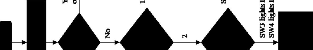
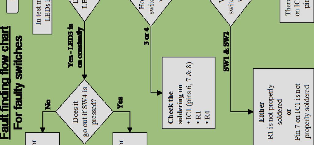
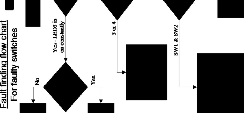
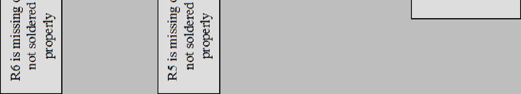
3 7 FIT THE IC INTO THE HOLDER The IC can be put into the holder, ensuring that the notch on the chip lines up with the notch on the holder. 8 SECURING THE BATTERY HOLDER Check that the board works before folding the battery holder under the board and fixing in place with the M3 nut and bolt. Checking Your Game PCB Check the following before you insert the batteries: Check the bottom of the board to ensure that: All holes (except the 5 large 3 mm holes) are filled with the lead of a component. All these leads are soldered. Pins next to each other are not soldered together. Check the top of the board to ensure that: The notch on the IC holder / IC is near the edge of the board. The flat edge of each of the LEDs is next to the switch. The colour bands on R7 are yellow, purple, black. Testing the PCB The software on the microcontroller has been specially designed to allow easy testing of the PCB. When the batteries are inserted and SW5 is in the on position, the game will: Illuminate LED1, LED2, LED3 & LED4 in sequence for one second each. o If the LEDs don t light in order, stop testing and look at the LED fault finding flow chart. Once the LEDs have gone out, pressing any of the four buttons will cause the LED next to it to light. o Check that all four buttons work, if this is not the case look at the switch fault finding flow chart. Turn the game off using SW5. If all four buttons tested OK, next time the game is turned on it will work normally.
4 Using the Game SW5 can be used to turn the game on and off (as indicated on the PCB). When the game is turned on LED1 & LED4 flash rapidly to indicate that a game should be selected. Press SW1 for the memory game or SW4 for the reactions game (both are marked on the PCB). If you wish to change the game you are playing turn the game off and back on and select the other game. Don't forget to switch it off when youre not playing otherwise you will flatten the batteries. Memory game The LEDs will flash a sequence. Simply copy this sequence. If you get it correct the LEDs will quickly flash in turn before the sequence is shown again with an extra LED on the end. When you do get it wrong the LEDs quickly flash in turn three times then your score is shown. The more LEDs you light the better you have done! Reactions game After a random amount of time one of the four LEDs will be illuminated. Simply press the button next to the LED before the LED goes off. If you have pressed the button fast enough then a short while later a new LED will turn on but you have less time to press the button to stay in the game. When you don't manage to press the LED fast enough the LEDs quickly flash in turn three times then your score is shown. The more LEDs you light, the better you have done!
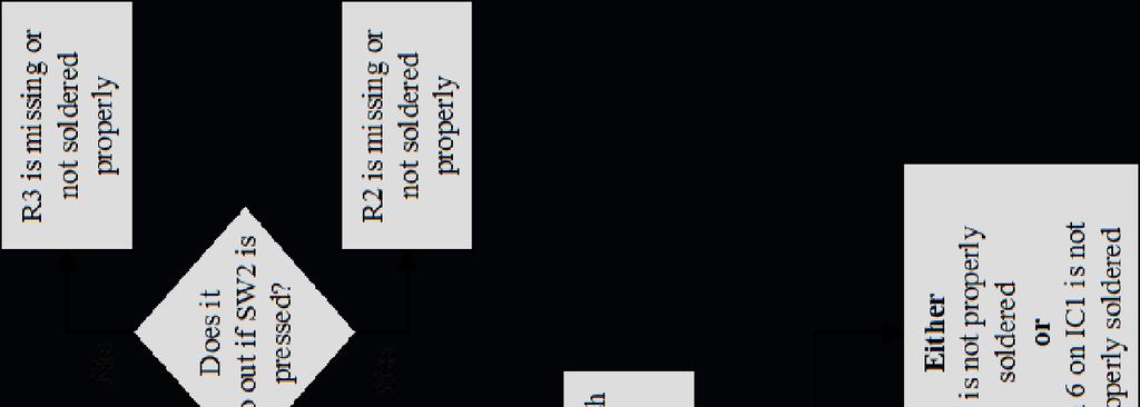
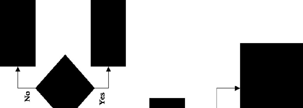
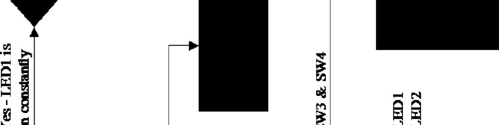
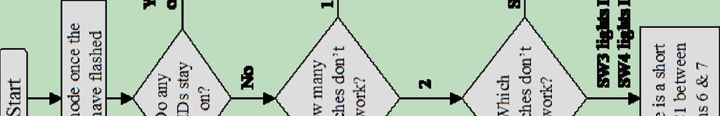
5 Fault Finding Fault finding flow chart For faulty LEDs Start Power the board up whilst watching the LEDs R7 (the 47 - colour bands yellow, purple, black) has been put in to R1-R6 The LEDs turned on but only very dimly Did the LEDs light? No LEDs turned on One or more LEDs turned on No - one of the LEDs was missing, but then came on at the same time as another LED No - One / two of the LED did not light Check The batteries are good and in the right way around The game is turned on IC1 is present and the notch is near the board edge IC1 pins 1, 2, 8 (nearest the board edge) are soldered properly R7 is present, and soldered properly SW5 is present, and soldered properly The LED that was missing is soldered in to the board the wrong way round Were the LEDs in sequence (LED1, 2, 3, 4)? Yes LEDs are working move on to switch flow chart How many LEDs didnt work? 2 1 Check For a solder shorts on one of the LEDs that didnt light IC1 pins 3 & 5 are soldered correctly For a solder short on IC1 between pins 1 & 2 or pins 2 & 3 The LED that did not light is not properly soldered
6
7 Designing the Enclosure When you design the enclosure, you will need to consider: The size of the PCB Where the LEDs are mounted and how big they are Where the switches are mounted and their size Note: The PCB is symmetrical and, therefore, its length and the position of the LEDs and switches is the same in the vertical direction as well as the horizontal dimensions shown below. This technical drawing of the game should help you to plan this. All dimensions are in mm. Mounting the PCB to the enclosure The drawing to the left shows how a hex spacer can be used with two bolts to fix the PCB to the enclosure. Your PCB has four mounting holes designed to take M3 bolts.
8 How the Game Works At the heart of the electronic circuit is a microcontroller. A microcontroller is, in effect, a small computer. The circuit uses a cleaver design to allow four switches and four LEDs to be connected to only five input / outputs. The switches are connected to an analogue to digital converter so that it gets a digital representation of the voltage on the input. A set of three resistors is used to make up a potential divider. As each of the resistors is the same value, an equal amount of voltage is present across each of these resistors. The top two resistors also have a switch across them. When the switch is pressed, the voltage across the resistor will become zero. So depending upon which of the two switches is pressed will depend upon what the voltage is at the point where it is fed into the PIC microcontroller. This allows the microcontroller to work out which button is pressed. The third resistor is used to prevent the batteries being rapidly flattened should both switches be pressed at the same time. The other two switches on the board work in the same way. This may sound overly complicated however it uses less input pins than switches with individual pull up resistors. The LEDs are driven by three outputs. Because the LED only works when current flows through it in one direction, the four LEDs can be turned on by changing the outputs to make one high whilst another is low. More than one LED can be turned on if a little dimmer by taking it in turns to turn the LEDs on hundreds of times a second. The 47 resistor limits the current that can flow through the LEDs. This protects the LED and controls the brightness.
9 Online Information Two sets of information can be downloaded from the product page where the kit can also be reordered from. The Essential Information contains all of the information that you need to get started with the kit and the Teaching Resources contains more information on soldering, components used in the kit, educational schemes of work and so on and also includes the essentials. Download from: This kit is designed and manufactured in the UK by Kitronik Every effort has been made to ensure that these notes are correct, however Kitronik accept no responsibility for issues arising from errors / omissions in the notes. Kitronik Ltd - Any unauthorised copying / duplication of this booklet or part thereof for purposes except for use with Kitronik project kits is not allowed without Kitroniks prior consent.
ELECTRONIC GAME KIT TEACHING RESOURCES. Version 2.0 BUILD YOUR OWN MEMORY & REACTIONS
 TEACHING RESOURCES SCHEMES OF WORK DEVELOPING A SPECIFICATION COMPONENT FACTSHEETS HOW TO SOLDER GUIDE BUILD YOUR OWN MEMORY & REACTIONS ELECTRONIC GAME KIT Version 2.0 Index of Sheets TEACHING RESOURCES
MONO AMPLIFIER KIT ESSENTIAL INFORMATION. Version 2.2 CREATE YOUR OWN SPEAKER DOCK WITH THIS
 ESSENTIAL INFORMATION BUILD INSTRUCTIONS CHECKING YOUR PCB & FAULT-FINDING MECHANICAL DETAILS HOW THE KIT WORKS CREATE YOUR OWN SPEAKER DOCK WITH THIS MONO AMPLIFIER KIT Version 2.2 Build Instructions
7 SEGMENT LED DISPLAY KIT
 ESSENTIAL INFORMATION BUILD INSTRUCTIONS CHECKING YOUR PCB & FAULT-FINDING MECHANICAL DETAILS HOW THE KIT WORKS CREATE YOUR OWN SCORE BOARD WITH THIS 7 SEGMENT LED DISPLAY KIT Version 2.0 Which pages of
8 PIN PIC PROGRAMMABLE BOARD (DEVELOPMENT BOARD & PROJECT BOARD)
") ESSENTIAL INFORMATION BUILD INSTRUCTIONS CHECKING YOUR PCB & FAULT-FINDING MECHANICAL DETAILS HOW THE KIT WORKS LEARN ABOUT PROGRAMMING WITH THIS 8 PIN PIC PROGRAMMABLE BOARD (DEVELOPMENT BOARD & PROJECT
ESSENTIAL INFORMATION BUILD INSTRUCTIONS CHECKING YOUR PCB & FAULT-FINDING MECHANICAL DETAILS HOW THE KIT WORKS LEARN ABOUT PROGRAMMING WITH THIS 8 PIN PIC PROGRAMMABLE BOARD (DEVELOPMENT BOARD & PROJECT
COLOUR CHANGING USB LAMP KIT
 TEACHING RESOURCES SCHEMES OF WORK DEVELOPING A SPECIFICATION COMPONENT FACTSHEETS HOW TO SOLDER GUIDE SEE AMAZING LIGHTING EFFECTS WITH THIS COLOUR CHANGING USB LAMP KIT Version 2.1 Index of Sheets TEACHING
QUIZ BUZZER KIT TEACHING RESOURCES. Version 2.0 WHO ANSWERED FIRST? FIND OUT WITH THIS
 TEACHING RESOURCES SCHEMES OF WORK DEVELOPING A SPECIFICATION COMPONENT FACTSHEETS HOW TO SOLDER GUIDE WHO ANSWERED FIRST? FIND OUT WITH THIS QUIZ BUZZER KIT Version 2.0 Index of Sheets TEACHING RESOURCES
ADD AN AUDIO MESSAGE TO YOUR PRODUCT WITH THIS RECORD & PLAYBACK KIT
 ADD AN AUDIO MESSAGE TO YOUR PRODUCT WITH THIS RECORD & PLAYBACK KIT BUILD INSTRUCTIONS Before you start take a look at the Printed Circuit Board (PCB). The components go in the side with the writing on
RECORD & PLAYBACK KIT
 TEACHING RESOURCES SCHEMES OF WORK DEVELOPING A SPECIFICATION COMPONENT FACTSHEETS HOW TO SOLDER GUIDE ADD AN AUDIO MESSAGE TO YOUR PRODUCT WITH THIS RECORD & PLAYBACK KIT Version 2.1 Index of Sheets TEACHING
TECHNOLOGY WILL SAVE US: THE LUMIPHONE
 TECHNOLOGY WILL SAVE US: THE LUMIPHONE This is a step-by-step guide to soldering your own Lumiphone. The equipment you should have at your station: goggles, soldering mat, soldering Iron, solder and side
MAKE AN RGB CONTROL KNOB.
 MAKE AN RGB CONTROL KNOB. This is a knob based colour changing controller that uses a custom programmed microcontroller to pack a lot of features into a small affordable kit. The module can drive up to
Introduction 1. Green status LED, controlled by output signal ST. Sounder, controlled by output signal Q6. Push switch on input D6
 Introduction 1 Welcome to the GENIE microcontroller system! The activity kit allows you to experiment with a wide variety of inputs and outputs... so why not try reading sensors, controlling lights or
Pixie Construction Notes
 Pixie Construction Notes PCB V2a February 4 th 2015 Please note that this document is still currently under revision and we apologise for any errors or omissions. Readers should feel free to e-mail any
AXE101 PICAXE-08M2 Cyberpet Kit
 AXE101 PICAXE-08M2 Cyberpet Kit The Cyberpet project uses a PICAXE-08M2 microcontroller with two LEDs as the pets eyes and a piezo sounder as a voice for the pet. The project also uses a switch so that
Nixie Clock Kit IN-12B color LED backlit Operation Manual Nixie Clock Kit IN-12B V6.0 ( All Right Reserved 2015 )
") Nixie Clock Kit IN-B color LED backlit Operation Manual Nixie Clock Kit IN-B V. ( All Right Reserved ) - - Operation Manual IN-B Nixie Clock Power for your Nixie Clock The clock does not include a wall
Nixie Clock Kit IN-B color LED backlit Operation Manual Nixie Clock Kit IN-B V. ( All Right Reserved ) - - Operation Manual IN-B Nixie Clock Power for your Nixie Clock The clock does not include a wall
Introduction 1. Digital inputs D6 and D7. Battery connects here (red wire to +V, black wire to 0V )
") Introduction 1 Welcome to the magical world of GENIE! The project board is ideal when you want to add intelligence to other design or electronics projects. Simply wire up your inputs and outputs and away
Introduction 1 Welcome to the magical world of GENIE! The project board is ideal when you want to add intelligence to other design or electronics projects. Simply wire up your inputs and outputs and away
Introduction 1. Green status LED, controlled by output signal ST
 Introduction 1 Welcome to the magical world of GENIE! The project board is ideal when you want to add intelligence to other design or electronics projects. Simply wire up your inputs and outputs and away
POINTS POSITION INDICATOR PPI4
 POINTS POSITION INDICATOR PPI4 Monitors the brief positive operating voltage across points motors when they are switched Lights a corresponding led on a control panel to show the last operation of each
DIY KIT MHZ 8-DIGIT FREQUENCY METER
 This kit is a stand-alone frequency meter capable of measuring repetitive signals up to a frequency of 50MHz. It has two frequency ranges (15 and 50 MHz) as well as two sampling rates (0.1 and 1 second).
E-TEXTILES STARTER PACK
 LEARN HOW TO SEW A CIRCUIT WITH THIS E-TEXTILES STARTER PACK WHITE LEDs BLUE LEDs LARGE COIN CELL MINIATURE COIN CELL SEWABLE ELECTRONICS INTRODUCTION TO ELECTRO-FASHION Electro-Fashion is Kitronik's own
Nixie Clock Type Frank 3
 Assembly Instructions And User Guide Nixie Clock Type Frank 3 Software version: 7R PCB Version: 11 April 09-1 - 1. INTRODUCTION 1.1 About the clock Nixie clock type Frank 3 is a compact design with all
VU Meter Buffer DIY Kit
 VU Meter Buffer DIY Kit Warning This document is distributed for educational purposes only. This equipment operates at potentially lethal voltages. Only trained, qualified personnel should operate, maintain,
MAIN PCB (The small one) OPEN MAIN BOARD BAG A
 OPEN MAIN BOARD BAG A") THANKS FOR CHOOSING ONE OF OUR KITS! This manual has been written taking into account the common issues that we often find people experience in our workshops. The order in which the components are placed
THANKS FOR CHOOSING ONE OF OUR KITS! This manual has been written taking into account the common issues that we often find people experience in our workshops. The order in which the components are placed
Nixie Clock Type Frank 2 Z570M
 Assembly Instructions And User Guide Nixie Clock Type Frank 2 Z570M Software version: 7R PCB Revision: 11 April 09-1 - 1. INTRODUCTION 1.1 About the clock Nixie clock type Frank 2 is a compact design with
Documentation VFD clock 8 a clock
 Documentation VFD clock 8 a clock This documentation is protected by our copyright. It must not be used for commercial purposes. Congratulations on your purchase of your VFD clock. To guarantee success
MOD028 GLOCKENSPIEL TECHNO-MUSIC-OLOGY
 MOD028 GLOCKENSPIEL TECHNO-MUSIC-OLOGY MOD028 - Techno-music-ology Kit Contents Motor Controller PCBs 14 220R (red red brown gold) resistors 2 330R (orange orange brown gold) resistors 16 1N4001 diodes
TKEY-K16. Touch CW automatic electronic keyer. (No moving parts no contacts) Assembly manual. Last review: March 15, 2018
 Assembly manual. Last review: March 15, 2018") TKEY-K16 Touch CW automatic electronic keyer (No moving parts no contacts) Assembly manual Last review: March 15, 2018 Commands and use manual of the K16 and Updates and news: www.ea3gcy.com Thanks for
TKEY-K16 Touch CW automatic electronic keyer (No moving parts no contacts) Assembly manual Last review: March 15, 2018 Commands and use manual of the K16 and Updates and news: www.ea3gcy.com Thanks for
Reaction Game Kit MitchElectronics 2019
 Reaction Game Kit MitchElectronics 2019 www.mitchelectronics.co.uk CONTENTS Schematic 3 How It Works 4 Materials 6 Construction 8 Important Information 9 Page 2 SCHEMATIC Page 3 SCHEMATIC EXPLANATION The
Mal-2 assembly guide v1.0
 Mal-2 assembly guide v.0 SONIC POTIONS Schematic and BOM The BOM can be found on Google Docs Prepare the PCB Separate the PCBs using some pliers. PCB We start with the lower PCB and assemble it beginning
Nixie Tube Clock Type Marsden
 Assembly Instructions And User Guide Nixie Tube Clock Type Marsden Software version: RTC-1.3 PCB Revision: 16 Aug 10-1 - 1. INTRODUCTION 1.1 About the clock Nixie clock type Marsden is a compact design
GUIDE TO ASSEMBLY OF ERICA SYNTHS DELAY MODULE
 If you are reading this, most probably, you are about to build Erica Synths DIY DELAY module. The module is 4mm deep, skiff friendly, has solid mechanical construction and doesn t require wiring. Erica
SEP Bright Pi v1.0 Assembly Instructions
 SEP Bright Pi v1.0 Assembly Instructions When you purchased your Bright Pi v1.0 kit, you should have received an anti-static bag with some components in it which will require soldering together in order
Lab 7: Soldering - Traffic Light Controller ReadMeFirst
 Lab 7: Soldering - Traffic Light Controller ReadMeFirst Lab Summary The two-way traffic light controller provides you with a quick project to learn basic soldering skills. Grading for the project has been
Light Emitting Diodes (LEDs)
") Light Emitting Diodes (LEDs) Example: Circuit symbol: Function LEDs emit light when an electric current passes through them. Connecting and soldering LEDs must be connected the correct way round, the diagram
Light Emitting Diodes (LEDs) Example: Circuit symbol: Function LEDs emit light when an electric current passes through them. Connecting and soldering LEDs must be connected the correct way round, the diagram
DSO138mini Troubleshooting Guide
 DSO138mini Troubleshooting Guide Applicable main board: 109-13800-00I Applicable analog board: 109-13801-00H 1. Frequently Found Problems 1) LCD completely dark. No backlight 2) LCD lights up but no display
Build Your Own Clone Super 8 Kit Instructions
 Build Your Own Clone Super 8 Kit Instructions Warranty: BYOC, Inc. guarantees that your kit will be complete and that all parts and components will arrive as described, functioning and free of defect.
SN-Class Nixie Clock Kits
 Assembly Instructions And User Guide SN-Class Nixie Clock Kits - 1 - REVISION HISTORY Issue Date Reason for Issue Number 1 20 November 2017 New document - 2 - 1. INTRODUCTION 1.1 About the How can the
Installing The PK-AM keyer and. from Jackson Harbor Press Operating: A Morse code keyer chip with pot speed control
 Installing The PK-AM keyer and from Jackson Harbor Press Operating: A Morse code keyer chip with pot speed control The PK-AM keyer is a modification for the PK-AM kit, it changes the AM transmitter to
Lab 7: Soldering - Traffic Light Controller ReadMeFirst
 Lab 7: Soldering - Traffic Light Controller ReadMeFirst Lab Summary The two way traffic light controller provides you with a quick project to learn basic soldering skills. Grading for the project has been
N3ZI Digital Dial Manual For kit with Serial LCD Rev 3.04 Aug 2012
 N3ZI Digital Dial Manual For kit with Serial LCD Rev 3.04 Aug 2012 Kit properly assembled and configured for Standard Serial LCD (LCD Not yet connected) Kit Components Item Qty Designator Part Color/Marking
Christmas LED Snowflake Project
 Christmas LED Snowflake Project Version 1.1 (01/12/2008) The snowflake is a follow-on from my Christmas star project from a few years ago. This year I decided to make a display using only white LEDs, shaped
Total solder points: 123 Difficulty level: beginner 1. advanced AUDIO ANALYZER K8098. audio gea Give your. . high-tech ILLUSTRATED ASSEMBLY MANUAL
 Total solder points: 123 Difficulty level: beginner 1 2 3 4 5 advanced AUDIO ANALYZER K8098 ra audio gea Give your. look high-tech ILLUSTRATED ASSEMBLY MANUAL H8098IP-1 Features & Specifications Features
Tube Cricket Build Guide
 Tube Cricket Build Guide The Tube Cricket is a small-wattage amp that puts out about 1 watt of audio power. With a 12AU7 tube-preamp and a JRC386 power amp, the Tube Cricket gives you great tone in a compact
Bill of Materials: Super Simple Water Level Control PART NO
 Super Simple Water Level Control PART NO. 2169109 Design a simple water controller in which electrodes are required to sense high and low water levels in a tank. Whenever the water level falls below the
USER MANUEL. SNIPE 2 Ref R13
 USER MANUEL SNIPE 2 Ref. 0141317R13 Contents 1. General Information 1-1. Introduction 1-2. Proper use and operation 1-3. Safety notes......... 2 3 3 2. Contents 2-1. Accessory included 2-2. Name of parts......
VU-1 VU Meter Kit Volume Unit Meter
 VU-1 VU Meter Kit Volume Unit Meter Simplicity Counts, Detail Matters. No part of this document may be reproduced, either mechanically or electronically, posted online on the Internet, in whole or in part,
Monday 28 January 2013 Morning
 Monday 28 January 2013 Morning GCSE DESIGN AND TECHNOLOGY Electronics and Control Systems A514/01 Technical Aspects of Designing and Making: Electronics *A528620113* Candidates answer on the Question Paper.
Assembly Instructions And User Guide. Nixie FunKlock. FunKlock Issue 4 (1 February 2017)
") Assembly Instructions And User Guide Nixie FunKlock - 1 - Issue Number Date REVISION HISTORY 4 1 February 2017 New diode for D2 3 27 December 2013 C7 / C8 error page 15 2 7 November 2013 Errors corrected
Assembly Instructions And User Guide Nixie FunKlock - 1 - Issue Number Date REVISION HISTORY 4 1 February 2017 New diode for D2 3 27 December 2013 C7 / C8 error page 15 2 7 November 2013 Errors corrected
24 Channel Demultiplexer
 USER GUIDE 24 Channel Demultiplexer Doc. No. : 88 601 27 (408481 A?0/3) k!rand Lighting Issue: 2 Date : Oct 1990 i; Contents INTRODUCTION................................ 1 Delivery Inspection..............................
Ten-Tec (865) Service Department:(865)
 Service Department:(865)") Ten-Tec (865) 453-7172 Service Department:(865) 428-0364 Installation Instructions for Ten-Tec Jupiter AT538K Tuner Kit The installation of the AT538K is divided into two steps. The first step is to reprogram
Ten-Tec (865) 453-7172 Service Department:(865) 428-0364 Installation Instructions for Ten-Tec Jupiter AT538K Tuner Kit The installation of the AT538K is divided into two steps. The first step is to reprogram
N3ZI Digital Dial Manual For kit with Backlit LCD Rev 4.00 Jan 2013 PCB
 N3ZI Digital Dial Manual For kit with Backlit LCD Rev 4.00 Jan 2013 PCB Kit Components Item Qty Designator Part Color/Marking PCB 1 LCD Display 1 LCD 1602 Volt Regulator 1 U1 78L05, Black TO-92 Prescaler
Fully ly Automaticti. Motorised Satellite t TV System. User s manual REV
 REV. 1.0 Fully ly Automaticti Motorised Satellite t TV System User s manual Customer Help Line: 1300 139 255 Support Email: support@satkingpromax.com.au Website: www.satkingpromax.com.au www.satkingpromax.com.au
Panzer 3.0 Assembly Instructions & Checklist
 Panzer 3.0 Assembly Instructions & Checklist Parts Included & Preparation Legend A. 5x Silver M4 Aluminum Screws B. 4x 10-24 Screws C. 8x 4-40 Pan head Screws D. 2x 4-40 Flat head Screws E. 2x 4-40 Nuts
Galilean Moons. dual amplitude transmutator. DIY ASSEMBLY MANUAL v1.02
 Galilean Moons dual amplitude transmutator DIY ASSEMBLY MANUAL v1.02 Contents Contents... 2 Introduction... 3 Eurorack Kit Assembly... 4 Resistors... 4 IC Sockets... 5 Ceramic/Film Capacitors... 5 Transistors
Main PCB (The small one)
") Thanks for choosing our kits! This manual is written taking with the problems that we usually find in our workshops in mind. Also the order is meant to make assembly as easy as possible. Some steps are
Thanks for choosing our kits! This manual is written taking with the problems that we usually find in our workshops in mind. Also the order is meant to make assembly as easy as possible. Some steps are
"Sophisticated Model Railroad Electronics"
 LOGIC RAIL TM "Sophisticated Model Railroad Electronics" TECHNOLOGIES 21175 Tomball Pkwy Phone: (281) 251-5813 Suite 287 email: info@logicrailtech.com Houston, TX 77070 http://www.logicrailtech.com Block
Nixie Clock Type Frank 3'
 Assembly Instructions And User Guide Nixie Clock Type Frank 3' - 1 - REVISION HISTORY Issue Number Date Reason for Issue 4 16 December 2016 New diode for D2 3 12 November 2012 Improved first clock test
DDS VFO CONSTRUCTION MANUAL. DDS VFO Construction Manual Issue 1.1 Page 1
 DDS VFO CONSTRUCTION MANUAL DDS VFO Construction Manual Issue 1.1 Page 1 Important Please read before starting assembly STATIC PRECAUTION The DDS VFO kit contains the following components which can be
Tip: Faller Mittelstadt Apartments with Controlled LED Lighting Date: , Addition
 Hi All, I have had the 130926 Mittelstadt apartments shown below on my layout for a long time and thought it was about time to add LED lighting to the buildings. With my success at upgrading the Faller
DEM 9ULNACK 3.4 GHz. PHEMT LNA amplifier complete kit assembly guide
 DEM 9ULNACK 3.4 GHz. PHEMT LNA amplifier complete kit assembly guide SPECIFICATIONS Noise Figure: < 0.8 db Gain: > 15 db Frequency Range: 3400-3500 MHz Input Voltage: 7-16 VDC Description: The 9ULNACK
Multi-Key v2.4 Multi-Function Amplifier Keying Interface
 Multi-Key v2.4 Multi-Function Amplifier Keying Interface ASSEMBLY & OPERATION INSTRUCTIONS INTRODUCTION The Harbach Electronics, LLC Multi-Key is a multi-function external device designed for the safe
Contents. 1. General Information. 2. Contents. 3. Operating Instruction. 4. Program update. 5. Trouble Shooting. 6. Specifications
 Contents 1. General Information 1-1. Introduction 1-2. Proper use and operation 1-3. Safety Notes 2. Contents 2-1. Accessory Include 2-2. Name of parts 3. Operating Instruction 3-1. Connection Diagram
Olympus BHM Microscope LED Illumination Andrew Menadue, UK
 Olympus BHM Microscope LED Illumination Andrew Menadue, UK I'm involved with electronics, both at work and at home and now and again I blow up an integrated circuit or have some dismantled equipment with
Azatrax Model Railroad Track Signal Control - Single Track
 Installation Guide Azatrax Model Railroad Track Signal Control - Single Track TS2 What it is: The TS2 operates one or two trackside block signals (one in each direction) on one track to simulate the block
Sign Illuminating Ballasts
 Sign Illuminating Ballasts A Complete Range Of Solutions From The Name You Trust Universal Lighting Technologies ( Universal ) is known throughout the sign business as a company that can set and meet today
uresearch GRAVITECH.US GRAVITECH GROUP Copyright 2007 MicroResearch GRAVITECH GROUP
 GRAVITECH.US uresearch GRAVITECH GROUP Description The I2C-7SEG board is a 5-pin CMOS device that provides 4-digit of 7-segment display using I 2 C bus. There are no external components required. Only
Nixie Clock Type Quattro'
 Assembly Instructions And User Guide Nixie Clock Type Quattro' - 1 - Issue Number Date REVISION HISTORY 2 8 Sept 2012 Errors corrected 1 27 July 2012 New document Reason for Issue - 2 - 1.1 Nixie Quattro
STROBOSCOPE LIGHT EFFECT KIT
 STROBOSCOPE LIGHT EFFECT KIT Easy to build stroboscope for general applications Flash frequency: 5 to 15 flashes per second Power supply: 110VAC Power consumption: 13W max. PCB dimensions: 50 x 75mm modifications
SceneStyle2 User Guide
 SceneStyle2 User Guide Mode Lighting (UK) Limited. The Maltings, 63 High Street, Ware, Hertfordshire, SG12 9AD, UNITED KINGDOM. Telephone: +44 (0) 1920 462121 Facsimile: +44 (0) 1920 466881 e-mail: website:
Timer Modules. MEU11 24 Hour Module, MEU17 7 Day Module (Without Housing)
") Timer Modules MEU11 24 Hour Module, MEU17 7 Day Module (Without Housing) EMU11 24 Hour Module, EMU17 7 Day Module (With Housing Giving panel mounting facility) Installation & Operating Instructions 1 1.
Timer Modules MEU11 24 Hour Module, MEU17 7 Day Module (Without Housing) EMU11 24 Hour Module, EMU17 7 Day Module (With Housing Giving panel mounting facility) Installation & Operating Instructions 1 1.
Fully ly Automaticti. Motorised Satellite t TV System. User s manual. ver 3.0.
 ver 3.0 Fully ly Automaticti Motorised Satellite t TV System User s manual Customer Help Line: 1300 139 255 Support Email: support@satkingpromax.com.au Website: www.satkingpromax.com.au www.satkingpromax.com.au
r.link Video-inserter RL5-UCON7-500 Compatible with Fiat vehicles with Uconnect 7inch infotainment
 r.link Video-inserter RL5-UCON7-500 Compatible with Fiat vehicles with Uconnect 7inch infotainment Video-inserter with 1 video input and 1 rear-view camera input Product features Video-inserter for factory-infotainment
ASSEMBLING. the. ECEbot. Printed Circuit Board: Part Three. Due Date. The Part Three assembly steps must be completed prior to:
 ASSEMBLING the ECEbot Printed Circuit Board: Part Three Due Date The Part Three assembly steps must be completed prior to: Prepared by R.C. Maher September 2008 Copyright 2008 Department of Electrical
Aspect 2 Circuit Digital Scene Control
 Aspect 2 Circuit Digital Scene Control S p e c i f i c a t i o n 2 circuits of trailing edge dimming 500W total between the two circuits Both circuits feature independent overload, short-circuit and open-circuit
Device for a inserting text into a video-signal
 ATV-LOGO Device for a inserting text into a video-signal 1998 2000 Wolfgang Otterbach, DL1IE All rights reserved. 10/2000 General The ATV-LOGO is an inexpensive but stable device for inserting text into
The ATT Deluxe Receiver
 The ATT Deluxe Receiver Operating Instructions Advanced Technology Tackle Advanced Technology Tackle UK The ATT Deluxe Receiver Located on the right hand side are 3 tactile buttons: the top one is used
Bill of Materials: Magic Color PART NO
 Magic Color PART NO. 2193838 Magic color is a guessing game. With this game you can surprise your friends and leave them with amazement, how the game guesses what they have in their minds. Only two selections
While the parts are already inventoried at the factory, please verify the inventory check as you go:
 Thank you for purchasing the kit for building the WJ9J DTMF controller. After building, you should read the document on operation (WJ9JDTMFControllerV5.pdf) in order to use. This is also in the link in
Atari PICO Composite Mod Board Installation Instructions:
 Atari PICO Composite Mod Board Installation Instructions: Installation Guide 6 Switch Atari 2600 6 Switch Video Mod Installation Guide Disclaimer: I am not responsible for any damage done to your Atari.
Modellbahn Digital Peter Stärz
 Modellbahn Digital Peter Stärz Dresdener Str. 68 D-02977 Hoyerswerda +49 3571 404027 www.firma-staerz.de info@firma-staerz.de 8-fold Track Occupancy Detector for digital systems with two-wire track (e.g.
Analog Style LED Clock
 Analog Style LED Clock Operation and Assembly Manual For use with PCB Rev 2.1 Copyright 2018 All Rights Reserved. Manual version 2.1c, for use with PCB revision 2.1, Software version 2.0.0. The electronic
Electrical connection
 (I)GSU 14C Ultrasonic Label Fork Dimensioned drawing en 06-2011/12 50109234-01 4mm 12-30 V DC 4 m/s We reserve the right to make changes DS_IGSU_14C_en.fm Ultrasonic forked sensor for universal application
SquareLED - Aura Bar & Matrix Beam Light 100
 SquareLED - Aura Bar & Matrix Beam Light 100 1. SAFETY INSTRUCTIONS Please read these instructions carefully they include the important information about the installation usage and maintenance of this
Lab Using The Multimeter And The Trainer
 Lab 2 Sierra College CIE-01 Jim Weir 530.272.2203 jweir43@gmail.com www.rstengineering.com/sierra 1. Using The Multimeter And The Trainer a. Plug the trainer power cord into a standard wall outlet (110
ANTUMBRA FADE MANUAL
 ANTUMBRA FADE MANUAL TABLE OF CONTENTS 01. INSTALLATION 4 02. BACK 5 03. FRONT 6 04. USE 7 05. LINK 8 06. BILL OF MATERIALS 9 07. BUILD NOTES 10 08. BACK 11 09. FRONT 14 10. MODIFICATION 15 11. FINISHED
"shell" digital storage oscilloscope (Beta)
") "shell" digital storage oscilloscope (Beta) 1. Main board: solder the element as the picture shows: 2. 1) Check the main board is normal or not Supply 9V power supply through the connector J7 (Note: The
"shell" digital storage oscilloscope (Beta) 1. Main board: solder the element as the picture shows: 2. 1) Check the main board is normal or not Supply 9V power supply through the connector J7 (Note: The
Nixie Clock Type IN-8 & NL840 Nixie'
 Assembly Instructions And User Guide Nixie Clock Type IN-8 & NL840 Nixie' - 1 - REVISION HISTORY Issue Number Date 4 15 December 2016 New diode for D2 3 30 August 2014 Typos 2 25 June 2014 Added NL840
The Micropython Microcontroller
 Please do not remove this manual from the lab. It is available via Canvas Electronics Aims of this experiment Explore the capabilities of a modern microcontroller and some peripheral devices. Understand
Prototyping & Engineering Electronics Kits Magic Mandala Kit Guide
 Prototyping & Engineering Electronics Kits Magic Mandala Kit Guide odysseyboard.com Please refer to www.odysseyboard.com for a PDF updated version of this guide. Magic Mandala Guide version 1.0, February,
Edge Connector Light Level Detector
 Description This is a simple tutorial demonstrating how to use a Kitronik edge connector breakout with the BBC micro:bit. The tutorial will cover measuring ambient light levels with an LDR and dimming
SHUTTLE WITH INFRA-RED DETECTION SAS2-IR
 SHUTTLE WITH INFRA-RED DETECTION SAS2-IR Shuttle Model Train Controller with Infra-Red Detection Automatically operates a train backwards and forwards along a single line. Train detection using Infra-red
Parts Checklist - Please note there is no resistor R3. Diodes, LED and transistors are polarized see construction stages
 Xtal Check Kit build Read me first! -------- UPDATED GUIDE------ September 12, 2018--------- The following steps are designed to get your Xtal check kit built and operational. This is a good beginner s
X-CHIP-100-DIP X-CHIP-100-SMD
 USER INSTRUCTIONS X-CHIP-00-DIP X-CHIP-00-SMD X-CHIP-00-DIP, 5 RGB LEDs(DIP), Length=00mm with PCB module X-CHIP-00-SMD, 5 SMD RGB LEDs, Length=00mm with PCB module PRODUCTION DESCRIPTION X-CHIP is a simple
Nixie Clock Type SixNix
 Assembly Instructions And User Guide Nixie Clock Type SixNix - 1 - Issue Number Date REVISION HISTORY Reason for Issue 6 20 March 2014 Removed WWVB Support 5 14 July 2012 New Board Issue - 19 July 12 4
Building the BX24-AHT
 Building the BX24-AHT file:///f /LASER/build-it.htm (1 of 8) [03/04/2002 5:21:52 PM] file:///f /LASER/build-it.htm (2 of 8) [03/04/2002 5:21:52 PM] Tips & Tricks Use a 25W or smaller soldering iron with
ATTENTION YOUR NEW KEY FOBS WILL NOT WORK UNTIL YOU HAVE LOADED THEM ON TO YOUR REMOTE CONTROL SYSTEM
 ATTENTION YOUR NEW KEY FOBS WILL T WORK UNTIL YOU HAVE LOADED THEM ON TO YOUR REMOTE CONTROL SYSTEM Please identify which remote control system is operating your roller shutter/garage door and follow the
XTAL Bank DDS Version 0.02 Sept Preliminary, highly likely to contain numerous errors
 XTAL Bank DDS Version 002 Sept 7 2012 Preliminary, highly likely to contain numerous errors The photo above shows the fully assembled Xtal Bank DDS with 2 DDS modules installed (The kit is normally only
Nixie Clock Kit V1.08 Assembly and Operation
 Nixie Clock Kit V1.08 Assembly and Operation Hardware Revision 14.05.2005 Software Version 6.0 Revision 19.04.2006 This document is copyrighted. No parts of this documentation may be used commercially.
Constructing and Operating: The Island Keyer
 Constructing and Operating: The Island Keyer Construction: General notes about building: The components should be inserted a few at a time, soldered in place and then the leads are clipped. Note that all
CR Signals Price List (N Gauge & General) April 2010
 April 2010") Welcome to CR Signals mail order price list price list and order form. Established in 2004, all of our products have been developed over the years and are hand built using the finest materials and latest
Welcome to CR Signals mail order price list price list and order form. Established in 2004, all of our products have been developed over the years and are hand built using the finest materials and latest
DD E SIG N E D & E N GIN EE R E. Holman Garden Lights App Instruction Manual. Android Android manual
 DD E SIG N E D & E N GIN EE R E Holman Garden Lights App Instruction Manual Android Android manual AUSTRALIAN Mounting the Controller Connecting your Lights Operating the App Troubleshooting Warranty Contact