Logic processing Catalogue PDE2619TCUK July 2009
|
|
|
- Prudence Irene Stephens
- 6 years ago
- Views:
Transcription
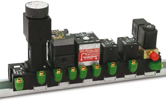


1 Logic processing Ctlogue PDE2619TCUK July 2009
2 Importnt! Before crrying out ny service work, ensure tht the vlve nd mnifold hve been vented. Remove the primry supply ir hose to ensure totl disconnection of the ir supply before dismntling vlves or blnk connection blocks. NB! ll technicl dt in this ctlogue is typicl only. The ir qulity is decisive for the vlve life: see IO WRNING FILURE OR IMPROPER ELECTION OR IMPROPER UE OF THE PRODUCT ND/OR YTEM DECRIBED HEREIN OR RELTED ITEM CN CUE DETH, PERONL INJURY ND PROPERTY DMGE. This document nd other informtion from, its subsidiries nd uthorized distributors provide product nd/or system options for further investigtion by users hving technicl expertise. It is importnt tht you nlyze ll spects of your ppliction nd review the informtion concerning the product or system in the current product ctlog. Due to the vriety of operting conditions nd pplictions for these products or systems, the user, through its own nlysis nd testing, is solely responsible for mking the finl selection of the products nd systems nd ssuring tht ll performnce, sfety nd wrning requirements of the ppliction re met. The products described herein, including without limittion, product fetures, specifictions, designs, vilbility nd pricing, re subject to chnge by nd its subsidiries t ny time without notice. LE CONDITION The items described in this document re vilble for sle by, its subsidiries or its uthorized distributors. ny sle contrct entered into by Prker will be governed by the provisions stted in Prker s stndrd terms nd conditions of sle (copy vilble upon request). 2
3 ummry ummry Pge ummry... Presenttion... TEX products... Pnorm - Operting informtions... pecific chrcteristics... Modulr sequencer... Logic elements... ub-bses nd timers... mplifiers nd sensor modules... Electro-modules... Impulse counters nd timers... ccessories... pre prts... Bses / Cells ssocitions... Dimensions


4 Presenttion Line mounted logic elements These cn either be mounted long the length of the line or locted in n enclosure. Two logic functions re vilble with this model : ND nd OR. Combinble logic elements These elements cn be combined with ech other enbling the ssembly of compct logic blocks. Three logic functions re provided : ND - OR nd inhibition NOT. In ddition to the combintion ssembly by integrl key, ech logic element includes mode selector which enbles, simply by pivoting the selector, choice between cscde mode or common, input mode : - cscde mode mens tht the element output corresponds to the input of the following element ; - common input mode sends one of the element's inputs to n input of the following element. The logic block obtined in this wy for ech pplictions re mounted in n enclosure on stndrd Omeg ril, re connected by instnt connections nd crry, on the front, their internl digrm to fcilitte ny intervention. elector in cscde position elector in common position ub-bse mounting logic elements s n lterntive, it is possible to use logic element suitble for mounting on 3-port sub-bses, the interconnections being mde by the sub-bses. The following cn be used : - 3-port sub-bses with common pressure, with common used s "input common" ; - 3-port "cscde" sub-bses. 4


5 Presenttion The specilized relys mounted on stcking sub-bses re complementry to the sequencers nd logic elements. ccording to the rely, it cn be used 3-port or 4-port sub-bse. 3-port sub-bses These re designed for the mounting of : - timers, - relys for bleed sensors, - pressure operted electricl contcts. 4-ports sub-bses These re designed for the mounting of : - memory relys, - mplifier relys for fluidic proxility sensors. The stndrd configurtion enbles the use of single pressure supply to ll the relys Locking of the key by the component Integrl key Blnking plug by the centre ports ; this is why the stcking "common pressure" sub-bses, with either ir pressure supply 3 or 4 ports, re ll designed to be used singly or combined in bnk trversed by pressure common. 5


6 Presenttion Production mchines fitted with pneumtic cylinders generlly repet defined sequencil cycle. The pneumtic sequencer commnds nd controls the correct opertion of the required cycle. Being modulr, the sequencer cn be esily configured to ech cycle encountered. It constitutes the bckbone of the pneumtic control. Logic elements nd specil relys re necessry to ensure the dditionl functions : sfety conditions, operting modes, time delys, etc... Composition The pneumtic sequencer comprises : - the stge modules corresponding to the cycle to be hed module step module devition til module run : module is used for ech stge of the GRFCET function chrt ; - the two modules, hed nd til, interlock the ssocition of the module onto Omeg ril nd enble the connection of the pressure common, of the reset to zero nd the connection loops between the lst nd the first module. devition module is fitted between the step modules to intercept the inter-module signls when the cycle includes prllel elements, restrts or the skipping of step. Dilogue The pneumtic sequencer fcilittes the mchine djustment dilogue nd the optionl dilogue. t the step module level, dilogue items include : - step indictor which signls the step ctivted ; - step reference mrking ; - mnul overrides for resetting the module to 0 or to1; - test point, enbling knowledge of the input nd output stte of ech module. t the closure module level, the reference mrkings enble : - connection of loops nd B necessry for cycle repetition ; - switching on of the sequencer ; -fitting of reset (REET) if the ppliction requires this. override movement utomtic connections between step modules feedbck signl mnul control for resseting the module to 1 test point mnul control for resetting the module to 0 step indictor step reference mrking Loop B Loop 6
7 Presenttion etting up The sequencer reproduces the GRFCET function digrm configurtion which defines the operting cycle : sequencer stge module corresponds to ech stge in the cycle. The ctivted stge module sends the control signl to the pressure vlve controlling the ction intended for the stge, then wits for the feedbck signl t the end of this ction before ctivting the next stge module in the sequencer. The ll pneumtic loop shown in the digrm revolves in this wy round the stge module, the sequencer ctivting stge by stge ech of the ctions to be crried out in the cycle order. Exmple This very simple exmple shows pneumtic press fitted with prt supply cylinder. bistble power vlve nd end of trvel sensors re ssocited with ech cylinder. The GRFCET digrm defines the required cycle. The initil stge is plced t the end to fcilitte obtining the cycle vi the sequencer. In the digrm, the sequencer reproduces the GRFCET digrm, sending step by step control signls (+, -, b+, b-) ccording to the feedbck signls (1, 0, b1, b0). trting cycle 7
8 Presenttion Bsic fetures Logic Function Logic ymbol Pneumtic Component Function ymbol Electricl Equivlent P I V E OR OR b (or both) + b Output is ON if t lest one of the inputs "" OR "b" is ON. F U N C T I O N ND nd b b Output is ON only if inputs "" ND "b" re ON. YE (Regenerte) (Regenerted) Output is ON nd regenerted if input "" is ON. C T I V E NOT (Inhibit) NOT Output is ON if input "" is OFF (nd if supply P is present). F U N C T I O N b "b" is n intermittent signl. "" inhibits "b". Output is ON if "b" is ON nd "" is OFF. MEMORY Input "" genertes output (ET). Output remins ON until removed by input "b" (REET). 8
9 TEX products TEX - Ex products complince ome products (PLL-, PLK-, PLN-, PLJ-, PLM-, PRD-, PRF-, PRT-, PM-, PV-1) re vilble certified TEX Lbels II 2 GD c 85 C zones 1, 2, 21, 22 certifiction n LCIE 04 TEX 6164X. ll these products re mrked with * in this technicl leflet. To obtin the TEX version of the product, dd -EX t the end of the order code Eg : PM-12-EX For more informtion plese refer to TEX Components technicl leflet : PDE2584TCUK-ev 9
10 TEX Tmosphère EXplosible Introduction to the Europen TEX directive Explosive tmospheres Directive 94/9/EC defines n explosive tmosphere s mixture of : ) flmmble substnces gses, vpours, mists or dusts b) with ir c) under specific tmospheric conditions d) in which, fter ignition hs occurred, combustion spreds to the entire flmmble mixture (NB: with regrd to dust, it my be tht not ll dust is combusted fter ignition hs occurred) n tmosphere with the potentil to become n explosive tmosphere during operting conditions nd/or under the influence of the surroundings is defined s potentilly explosive tmosphere. Products covered by directive 94/9/EC re defined s intended for use in potentilly explosive tmospheres. Hrmonised Europen TEX stndrd The Europen Union hs dopted two hrmonised directives in the field of helth nd sfety. The directives re known s TEX 100 nd TEX 137. Directive TEX 100 (94/9/EC) lys down minimum sfety requirements for products intended for use in potentilly explosive tmospheres in Europen Union member sttes. Directive TEX 137 (99/92/EC) defines minimum requirements for helth nd sfety t the workplce, for working conditions nd for the hndling of products nd mterils in potentilly explosive tmospheres. This directive lso divides the workplce into zones nd defines criteri by which products re ctegorised within these zones. The tble below describes the zones in n instlltion where there is potentil for explosive tmospheres. The owner of the instlltion must nlyse nd ssess the re in which the explosive gs/dust mixture my occur, nd if necessry must divide it into zones. This process of zoning then llows the correct plnt nd equipment to be selected for use in the re. Zone 2 Ctegory 3 Zone 1 Ctegory 2 Zone 0 Ctegory 1 Zones Presence of potentilly explosive tmosphere Type of risk Gs Dust G D 0 20 Present continuously or for long periods. Permnent Likely to occur in norml opertion occsionlly. Potentil Not likely to occur in norml opertion but, if it does occur, Miniml. will persist for short period only. The TEX directive hs been in force throughout the Europen Union since 1 July 2003, replcing the existing divergent ntionl nd Europen legisltion relting to explosive tmospheres. Plese note tht for the first time, the directive covers mechnicl, hydrulic nd pneumtic equipment nd not just electricl equipment s before. With regrd to the Mchinery directive 98/37/EC, note tht number of externl requirements in 94/9/EC refer to hzrds rising from potentilly explosive tmospheres, where the Mchinery directive only contins generl requirements relting to explosion sfety (nnex I 1.5.7). s result, directive 94/9/EC (TEX 100) tkes precedence over the Mchinery directive with regrd to explosion protection in potentilly explosive tmospheres. The requirements in the Mchinery directive re pplicble to ll other risks relting to mchinery. In most cses full certifiction is not required, much more simple Risk ssessment s detiled in the Directive,for the products to be supplied will suffice. t the moment we re conducting Risk ssessments in ccordnce with the Directive, on brod rnge of core products which will be published on the web site. more limited rnge of products will hve the full TEX certifiction where this is deemed necessry. 10
11 TEX Tmosphère EXplosible Levels of protection for the vrious equipment ctegories The vrious equipment ctegories must be cpble of operting in ccordnce with the mnufcturer s operting specifictions t defined levels of protection. Level of Ctegory Type of protection Operting specifictions protec- Group Group tion I II Very M1 Two independent mens of protection or sfety, ensuring tht The equipment remins energised nd high the equipment remins functionl even in the event of two fults functionl even with n explosive occurring independently of ech other. tmosphere present. Very 1 Two independent mens of protection or sfety, ensuring tht The equipment remins energised nd high the equipment remins functionl even in the event of two fults functionl in zones 0, 1, 2 (G) nd/or occurring independently of ech other. zones 20, 21, 22 (D). High M2 Protection suitble for norml opertion nd severe The equipment is de-energised in the operting conditions. event of n explosive tmosphere. High 2 Protection suitble for norml opertion nd frequent fults, or The equipment remins energised nd funcequipment in which fults normlly hve to be tken into ccount. tionl in zones 1, 2 (G) nd/or zones 21, 22 (D). Norml 3 Protection suitble for norml opertion. The equipment remins energised nd functionl in zones 2 (G) nd/or zones 22 (D). Definition of groups (EN ) Group I Equipment intended for use in underground prts of mines s well s those prts of surfce instlltions of such mines likely to be endngered by flmmble vpours nd/or flmmble dusts. Group II Equipment intended for use in other plces exposed to explosive tmospheres. Group I II mines, combustible vpours other potentilly explosive tmospheres (gses, dust) Ctegory M1 M tmosphere* G D G D G D Zone * G gs nd D dust Temperture clsses Clssifiction of flmmble gses nd vpours on the bsis of ignition temperture. Temperture clss T1 450 T2 300 T3 200 T4 135 T5 100 T6 85 Mxi. llowed temperture on the surfce of the mteril ( C) Prker components out of scope of the TEX Directive : Essentil elements with the relible use of the products nd protection systems, but not hving n utonomous function nor n own ignition source. Declrtion of conformity The product ctlogues contin copies of the declrtion of conformity demonstrting tht the product meets the requirements of directive 94/9/EC. The declrtion is only vlid in conjunction with the instructions contined in the instlltion mnul relting to the sfe use of the product throughout its service life. The instructions relting to the conditions in the surrounding re re prticulrly importnt, s the certificte is invlidted if the instructions re found not to hve been dhered to during opertion of the product. If there is ny doubt s to the vlidity of the certificte of conformity, contct Prker Hnnifin customer service. Opertion, instlltion nd mintennce The product instlltion mnul contins instructions relting to the sfe storge, hndling, opertion nd servicing of the product. The mnul is vilble in different lnguges, nd cn be downloded from This document must be mde ccessible in suitble plce ner where the product is instlled. It is used s reference for ll personnel uthorised to work with the product throughout its service life. We, the mnufcturer, reserve the right to modify, extend or improve the instlltion mnul in the interests of the users. For more informtion bout TEX see EUs homepge: 11
12 Pneumtic utomtion; Control module Time dely Rely Rely function eries PM, PLM PLL, PLK PLL, PLK D PLN- C, PLJ PRT PLM Function Modulr tnd lone tckble ubbse mtd Time rely Memory sequencer logic cell logic cell logic cell Pneum. Rely Rely Operting Pressure 3 to 8 br 3 to 8 br 3 to 8 br 3 to 8 br 3 to 8 br 3 to 8 br torge temperture -15 C to +70 C -15 C to +70 C -15 C to +70 C -15 C to +70 C -15 C to +70 C -15 C to +70 C Working temperture -40 C to +60 C -40 C to +60 C -40 C to +60 C -40 C to +60 C -40 C to +60 C -40 C to +60 C Flow, Nl/min t 6 br / Flow, Kv 1,8 1,8 1,8 1/1,8 1,8 1,8 Response time Commuting time of the primry cting cell: 2 to 3 ms Mechnicl life t 6 br, 10 million 100 million 100 million 10 million 10 million 10 million 20 C 1 Hz cycles cycles cycles cycles cycles cycles hocks nd Vibrtions ccording to IEC nd IEC Connection Push-in connection Ø4 mm Mounting ll positions ll positions ll positions ll positions ll positions ll positions Refer to pge Mteril Generl Chrcteristics Vlve member - set : Body : Csing - End pltes : Vlve plte : els : prings : crews : Poppets : elf lubricting cetl - cermic Polymide reinforced fibreglss nodised luminium Zmk Nitrile tinless steel tinless steel Polyuréthne Fluid : ir or inert gs filtered 40 µ clss 5 ccording to IO dry clss ccording to service temperture non-lubricted, or lubricted torge temperture : -40 C to + 70 C Low temperture climtic : ccording to EN , test d High temperture climtic : ccording to EN , test Bd hock nd Vibrtions : ccording to IEC nd IEC lt spry test : ccording to IO 9227, 168 h olenoid orifice : 1.2/1.3mm Power (DC) : 6 to 6.8W Voltge tolernce : +/- 30% Duty cycle : 100% Electricl connection : Din 12
13 Operting informtions Rely functions Pressure witch olenoid ctutor Counters nd Timers PRD PRF PRE, P1 PR PCT, PCP 2147 PCM mplifier ensor Pressure olenoid Counter Binry Timers rely rely switch ctutor Counter 3 to 8 br 3 to 8 br 3 to 8 br 3 to 8 br 2 to 8 br 0 to 10 br 2 to 6 br -15 C to +70 C -15 C to +70 C -15 C to +70 C -15 C to +70 C 0 C to +60 C 0 C to +70 C 0 C to +60 C -40 C to +60 C -40 C to +60 C -40 C to +60 C -40 C to +40 C -0 C to +50 C -0 C to +60 C ,8 0, Commuting time of the primry 2 to 3 ms 8 to 12 ms Reset time Reset time cting cell: 2 to 3 ms 150 ms 200 ms 10 million 10 million 10 million 10 million 10 million 50 million 5 million cycles cycles cycles cycles cycles cycles cycles ccording to IEC nd IEC Push-in connection Ø4 mm ll positions ll positions ll positions ll positions ll positions ll positions ll positions
14 pecific chrcteristics PRD ignl pressure () : uxiliry supply pressure (p) : Consumption : Operting frequency : 0,5 to 2 mbr (mximum permissible overpressure 200 mbr) 100 to 200 mbr t 100 mbr with 0 : 3l/min NR 10 Hz (with mnul control) PRF Operting pressure : Nozzle Ø : Nozzle consumption : 3 to 8 br 0,3 mm 2 Nl/min per br PR Consumption : Direct current : seled 5 W lternting current : seled 6 V ; inrush 20 V Voltge rnge : 0,9 to 1,05 Un tndrd voltges : 24 VDC ; 48 VDC ; 24 VC ; 115 VC ; 230 VC Rting : 100 % Connection : Plug -in connector, Ø 9 mm cble entry, terminl cpcity 1,5 mm 2 Nominl insultion voltge : 660 V C or V DC (with mnul control) Protection degree : IP 65 PRE Trip pressure : 2,2 to 3 br Depilot pressure : 2 to 2,6 br Mx. operting frequency : 10 Hz Nominl insultion voltge : 660 V C or V DC Nominl therml rting : 10 Protection degree : IP 65 Connection : Plug -in connector, Ø 9 mm cble entry, terminl cpcity 1,5 mm 2 Function : NO contct P1-P Fixed trip pressure : 1,3 br djustble trip pressure : 2 to 5 br Nominl therml rting : 10 Mx. operting frequency : 10 Hz Nominl insultion voltge : 660 V C or V DC Protection degree : IP 40 Function : Open/Closed contct 14
15 Modulr sequencer tep modules Type ymbol Logic Description Connection Weight Order code function Visul indiction With PB-12 sub-bse Ø4 mm 0,175 PM-12 * of pneumtic wivel push-in output nd mnul override Without With PB-12 sub-bse Ø4 mm 0,170 PM-B12 * mnul override wivel push-in et of hed nd til modules Type ymbol Logic Connection Weight Order code function B R P B Ø6 mm Ø4 mm 0,080 PE-12 wivel push-in connection wivel push-in Devition modules Type ymbol Logic Connection Weight Order code function B B R Used for prllel, optionl, Ø4 mm 0,050 PD-12 repet sequenses nd wivel push-in skip step for the remote reset of 0,050 PD-B12 the lst step module * TEX version vilble Order code exmple : PM-12-EX Indictes stocked product. 15
16 Modulr sequencer dditionl step module interlock Type ymbol Logic Connection (1) Weight Order code function connection My be mounted between Ø4 mm 0,045 PV-12 * the sub-bse nd the step wivel push-in module to interrupt the sequence if sensor is found to be fulty (1) For other type of connections contct Technicl les Deprtment tep module without sub-bse To be used with PB-12 sub-bses Type ymbol Logic Description Weight Order code function Visul indiction With 0,135 PM-10 * of pneumtic mnul override output Without 0,130 PM-B10 mnul override tep module sub-bse Type Description Connection (1) Weight Order code ub-bse Ø4 mm 0,040 PB-12 wivel push-in (1) For other type of connections contct technicl sles Technicl les Deprtment Min dt for Line mounted elements Type ymbol Logic Description Connection Weight Order code function ND ingle module Ø4 mm 0,07 PLL-11 * tright push-in & b 1 OR ingle module Ø4 mm 0,07 PLK-11 * tright push-in b crew nd clip Enbles line mounted logic 0,02 PZM-L199 ssembly elements to be ttched to DIN ril (old per pck of 10) * TEX version vilble Order code exmple : PV-12-EX Indictes stocked product. 16
17 Logic elements Min dt for Combinble elements Type ymbol Logic Description Connection (1) Weight Order code function & ND With built-in key for Ø4mm 0,08 PLL-B12 * combintion nd operting wivel push-in mode selection b 1 OR With built-in key for Ø4mm 0,08 PLK-B12 * combintion nd operting wivel push-in mode selection b & NOT With built-in key for Ø4mm 0,08 PLN-B12 * combintion nd operting wivel push-in mode selection b INPUT With built-in key for Ø4mm 0,08 PLE-B12 combintion, clip for swivel push-in mounting on DIN ril nd blnking plte for closing bnk of combined elements (1) For other type of connections contct Technicl les Deprtment Min dt for ub-bse mounted element Type ymbol Logic Description Weight Order code function (For use with 3 port sub-bse, type PZU plese see pge 18) & ND With visul indiction 0,03 PLL-C10 * of pneumtic output signl 1 OR With visul indiction 0,03 PLK-C10 * of pneumtic output signl & NOT With visul indiction 0,03 PLN-C10 * inhibit of pneumtic input/output signl stndrd & NOT With visul indiction 0,03 PLN-D10 * inhibit on of pneumtic input/output signl threshold YE With visul indiction 0,03 PLJ-C10 * regenerte of pneumtic input/output signl Indictes stocked product. * TEX version vilble Order code exmple : PLL-B12-EX 17
18 ub-bses nd timers ub bse mounted elements Type ymbol Logic Description Connection (1) Weight Order code function 3-port sub-bses (2) With common Ø4 mm 0,04 PZU-12 input wivel push-in Cscde Ø4 mm 0,05 PZU-C12 wivel push-in 4-port sub-bses (2) For combintion with Ø4 mm 0,05 PZU-B12 memory rely (see next pge) nd mplifier rely (see next pge) wivel push-in Input module Ø4 mm 0,05 PZU-E12 wivel push-in (1) For other type of connections contct Technicl les Deprtment (Ex : M5 connection PZU-E15) (2) Cn be used singly or in combintion. Mounting methods: On DIN ril with built in clip, on surfce mounting using screws M4x25 Min dt for time dely relys Type Function Timing Connection (1) Weight Order code rnge Complete with sub-bse PZU-12 Output fter 0,1 to 30 s Ø4 mm 0,17 PRT-12 * timed period wivel push-in Without sub-bse For sub-bse Output fter 0,1 to 3 s 0,13 PRT-E10 * PZU-12 or PZU-C12 t 1 0 timed period 0,1 to 30 s 0,13 PRT-10 * 10 to 180 s 0,13 PRT-B10 * t 1 0 Output during 0,1 to 3 s 0,13 PRT-F10 * timed period (3) 0,1 to 30 s 0,13 PRT-C10 * 10 to 180 s 0,13 PRT-D10 * Tmper proof cp 0,01 L9-D901 * TEX version vilble Order code exmple : PZU-12-EX (1) For other type of connections contct Technicl les Deprtment (3) Cn be used to provide n impulse genertor Indictes stocked product. 18
19 mplifiers nd sensor modules Min dt for Memory relys Type ymbol Description Connection (1) Weight Order code Complete with sub-bse PZU-B12 With priority reset signl Ø4 mm 0,19 PLM-12 * nd visul indiction wivel push-in With mnul override P X Y Without sub-bse For sub-bse PZU-B12 With priority reset signl 0,14 PLM-10 * nd visull indiction With mnul override P X Y Without mnul override 0,13 PLM-B10 Min dt for mplifier relys Type ymbol Description Connection (1) Weight Order code Complete with sub-bse PZU-B12 This rely is used to mplify Ø4 mm 0,18 PRD-12 * the low pressure signl wivel push-in P p provided by fluidic proximity sensor to useble level With mnul override Without sub-bse For sub-bse PZU-B12 This rely is used to mplify 0,13 PRD-10 * the low pressure signl P provided by fluidic proximity p sensor to useble level With mnul override Min dt for ensor relys Type ymbol Description Connection (1) Weight Order code Complete with sub-bse PZU-12 This rely is used to provide supply Ø4 mm 0,07 PRF-12 * to bleed sensor nd to generte wivel push-in pneumtic signl equl to its supply pressure Without sub-bse For sub-bse PZU-12 This rely is used to provide supply 0,03 PRF-10 * or PZU-C12 to bleed sensor nd to generte pneumtic signl equl to its supply pressure * TEX version vilble Order code exmple : PLM-12-EX Indictes stocked product. (1) For other type of connections contct your Technicl les Deprtment 19
20 Electro-modules Min dt for olenoid ctutors Type ymbol Voltge Lod Connection Weight Order code Complete units, solenoid nd cble plug 24 V ~ 50/60 Hz 8,5 V Mnul 22 mm 0,17 PR-121B override Plug-in 24 V 6 W Mnul 22 mm 0,17 PR-122B override Plug-in 115 V ~ 50 Hz 8,5 V Mnul 22 mm 0,17 PR-121F 120 V ~ 60 Hz override Plug-in 230 V ~ 50 Hz 8,5 V Mnul 22 mm 0,17 PR-121M 240 V ~ 60 Hz override Plug-in olenoid mounting bse For mounting the solenoid Mnul 0,09 PR-D10 coil nd plunger on override 3-port modulr sub-bses type PZU-, see pge 18 olenoid coil with plunger nd 24 V* 6 W 0,135 PV-F102B 22 mm 48 V* 6 W 0,135 PV-F102E plug-in connector (4) 24 VC 50/60 Hz 8,5 V 0,135 PV-F101B 48 VC 50/60 Hz 8,5 V 0,135 PV-F101E 115 VC 50 Hz/ 8,5 V 0,135 PV-F101F 120 VC 60 Hz 230 VC 50 Hz 8,5 V 0,135 PV-F101M 240 VC 60 Hz 255 VC 50 Hz 8,5 V 0,135 PV-F101U * Versions vilble for opertion in explosive tmospheres. - Conforming to certificte LCIE X - Electricl equipment conforming to hrmonised Europen stndrds EN dted Mrch 1977 (NFC dted My 1982) EN dted Mrch 1977 (NFC dted My 1982) - Referencing code EExe ll T4 (consult Technicl les Deprtment) (4) Cn be fitted with LED indictor nd suppression, PV ZF Min dt for Pressure switches Type ymbol Electricl Pneumtic Connection Weight Order code chrcteristics chrcteristics Electric/Pneumtic Complete unit with sub-bse, solenoid nd cble plug N/O contct Mnul 22 mm 0,13 PRE-12 B override Plug-in Ø4 mm wivel push-in Without sub-bse B N/O contct Mnul 22 mm 0,04 PRE-10 override Plug-in Ø4 mm wivel push-in Line mounted B 1 CO contct Fixed operting Mnul Ø4 mm 0,05 P1-P /250 V threshold override Push-in 1 CO contct djustble ope- Mnul Ø4 mm 0,05 P1-P /250 V rting threshold override Push-in Indictes stocked product. 20
21 Impulse counters nd timers Min dt for Impulse counters Type ymbol Type Counting rnge Mounting Weight Order code Totlising counters X Y 0 P Pneumtic or ufce mounting 0,08 PCT-11 mnul reset Flush mounting 0,06 PCT-B11 Pre-selection counters Z Y 0 P dditionl with Flush mounting 0,12 PCP-11 pneumtic or mnul reset uto reset Flush mounting PCP-111 Z Y 0 ubtrction with Flush mounting 0,11 PCP-11 pneumtic or mnul reset Binry counters Type Description Weight Order code Pneumtic ctuted 0, Electricl ctuted 0, Min dt for Timers Type ymbol Type Time bse Time rnge Weight Order code Digitl disply X Y X Y mn 0 0 P P With pneumtic or 1 second 1 second to 0,20 PCM-11 mnul reset 27 hours 1 minute 1 minute to 0,20 PCM-B11 69 dys 2 minutes 3 to 100 minutes 0,20 PCM-E11 Clibrted dil 2 1 second 2 to 30 seconds 0,05 PCM-F11 1 second 20 to 300 seconds 0,05 PCM-G11 t 1 Indictes stocked product. 21
22 ccessories Mounting bezels Type Description Weight Order code For PCM-F11 nd PCM-G11 0,015 PXC-ZM6075 mounting in 60 x 75 mm cut-out For PCM-F11 nd PCM-G11 0,015 PXC-ZM7272 mounting in 72 x 72 mm cut-out Bezels for DIN ril mounting Type Description Weight Order code For (non-reversible) clip-on mounting of 0,020 PXC-Z35 PCM-F11 nd PCM-G11 on push-in connection sub-bse 35 mm DIN ril ltching device 0,010 PXC-ZE35 for PXC-Z35 sub-bses Lockble cover Degree of protection IP 55 Type Description Weight Order code Trnsprent cover key lockble 0,025 PXC-B1 for 60x75 bezel for PCP-11, PCP-11, PCP-M11, PCP-MB11 For PCT-B11 0,018 PXC-1 Indictes stocked product. 22
23 pre prts els for step modules nd dditionl interlock modules Type Bse component Weight Order code 1 set of 10 flt sels PM-12 0,038 PPR-L01 PM-B12 PV-12 PB-12 For logic elements nd relys for mounting on modulr sub-bses Type Bse component Weight Order code 1 lot of 100 O-ring sels comprising : PLJ-C10 0,015 PPR-L04-10 sels for ports with inputs filters - 90 sels for ports without input filter PLK-C10 PLL-C10 PLN-C10 PLN-D10 PRT-.. PRF-10 For mplifier relys Type Bse component Weight Order code 1 lot of 10 Mylr diphrgms PRD-10 0,004 PPR-L08 PRD-12 23
24 Bses / Cells ssocitions Bse usge - hows which components cn be mounted with which bse types Element Order code Type 2-Port 3-Port 4-Port 6-Port tcking PZU-12 PZU-B12 P-B12 tcking PZU-C12 Inline BNC3P20 BNC3P10 Inline BPB3P20 BPB3P10 tep Module tep Module with Overrides PM-10 X tep Module without Override PM-B10 X Logic ND PLL-C10 X OR PLK-C10 X YE PLJ-C10 X NO PLN-C10 X Threshold NOT PLN-D10 X Relys ensor PRF-10 X olenoid PR-10 X X Electric Pressure witch PRE-10 X X E/P Pressure witch LNOTP10 X Electric Pressure switch LP10 X X Vcuum / Electric LPV10 X X Timers Timer (NNP) Rely PRT-10 X* X Timer (NNP) Rely PRT-B10 X* X Timer (NNP) Rely PRT-E10 X* X Timer (NNP) Rely PRT-C10 X* X Timer (NNP) Rely PRT-D10 X* X Timer (NNP) Rely PRT-F10 X* X Other Relys Memory Rely PLM-10 X X mplifier Rely PRD-10 X X * Functionlity must be checked. 24
25 Bses / Cells ssocitions Fitting color code Port Lbel Color upply P 2 Blck / None ignl 1 Green Output 3 Red equencer input power modules Entry Module Hed / Til Used with Bse PZU-E12 PE-12 * PZU-12 PB-12 ** PZU-C12 PZU-B12 * PE-12-EX (TEX version) * PE-127 (U.. version) ** PB-12-EX (TEX version) 25
26 Dimensions Dimensions, Logic processing Modulr sequencer PM- 12 PD-12 PD-B12 PE-12 PM-10 PE-12 PV- 10 PM R P B B R B B , ,5 Ø6 mm push-in connections Ø4 mm push-in connections ,5 48, ,5 48,5 Line mounted logic elements PLL-11 nd PLK-11 PZM-L199 1 vis M Ø4, DIN ril Combinble logic elements PLE-B12 PLL-B12 PLK-B12 nd PLN-B Clip Pressure indictor & 1 & 40 Ø4, , Ø4 mm push-in connections Logic elements mounted on 3-port modulr sub-bses PZU-E12 PLJ-C10 PLN-C10 PLK-C10 nd PLL-C10 mounted on PZU-C12 nd PZU PLJ- C10 PLN- C10 PLK- C10 PLL- C & 1 & PZU- E12 PZU- C12 PZU- C PZU- 12 PZU DIN ril 26
27 Dimensions 3 nd 4-port modulr sub-bses PZU-E12 PZU-C12 PZU-12 Ø4, Ø4,2 PZU-B Clip Relys mounted on 3-port modulr sub-bses PRT-12 PRF-12 PRE-12 PR-121 nd PLN-D DIN ril 97 PRT-12 PRF-12 PRE-12 PR-121. PLN-D Relys mounted on 4-port modulr sub-bses PLM-12 nd PRD Pressure switch P1-P1091 DIN ril 77,5 17,517,5 n. modules17,5 40,5 Ø3 mm djusting screw 27
28 Dimensions Totlising counters PCT-11 PCT-B XØ Z 32 Y Preselection counters PCP-11 nd PCP-11 2XØ4,5 2XØ4, , , (1) Connexions Ø4 mm push-in instntnées Ø4 mm connections Z Y P , ,5 32,5 62,5 60 Connexions Ø4 mm push-in instntnées Ø4 mm connections Binry counters PCM-11 nd PCM-B (4.5) Di. 4 Plces.177 (4.5) Di. 4 Plces 1/4" Port 5 Plces 1/4" Port 5 Plces Brether Exhust Brether Exhust 28
29 Dimensions Digitl disply timers PCM-11 nd PCM-B11 2XØ4,5 X P Y 23 Timers with clibrted dil PCM-F11 nd PCM-G ,9 27,2 12 mx. 11, ,6 58, , Ø4 mm push-in connections 13,5 32, , ,5 7,8 10,4 21,8 Ø4 mm push-in connections Connexions instntnées Ø 4 mm 29
30 30
31 31
32 Prker Worldwide E UE, Dubi Tel: prker.me@prker.com R rgentin, Buenos ires Tel: T ustri, Wiener Neustdt Tel: +43 (0) prker.ustri@prker.com T Estern Europe, Wiener Neustdt Tel: +43 (0) prker.esteurope@prker.com U ustrli, Cstle Hill Tel: +61 (0) Z zerbijn, Bku Tel: prker.zerbijn@prker.com BE/LU Belgium, Nivelles Tel: +32 (0) prker.belgium@prker.com BR Brzil, Cchoeirinh R Tel: BY Belrus, Minsk Tel: prker.belrus@prker.com C Cnd, Milton, Ontrio Tel: CH witzerlnd, Etoy Tel: +41 (0) prker.switzerlnd@prker.com CL Chile, ntigo Tel: CN Chin, hnghi Tel: CZ Czech Republic, Klecny Tel: prker.czechrepublic@prker.com DE Germny, Krst Tel: +49 (0) prker.germny@prker.com DK Denmrk, Bllerup Tel: prker.denmrk@prker.com E pin, Mdrid Tel: prker.spin@prker.com FI Finlnd, Vnt Tel: +358 (0) prker.finlnd@prker.com ll rights reserved. FR Frnce, Contmine s/rve Tel: +33 (0) prker.frnce@prker.com GR Greece, thens Tel: prker.greece@prker.com HK Hong Kong Tel: HU Hungry, Budpest Tel: prker.hungry@prker.com IE Irelnd, Dublin Tel: +353 (0) prker.irelnd@prker.com IN Indi, Mumbi Tel: IT Itly, Corsico (MI) Tel: prker.itly@prker.com JP Jpn, Tokyo Tel: +(81) KR outh Kore, eoul Tel: KZ Kzkhstn, lmty Tel: prker.esteurope@prker.com LV Ltvi, Rig Tel: prker.ltvi@prker.com MX Mexico, podc Tel: MY Mlysi, hh lm Tel: NL The Netherlnds, Oldenzl Tel: +31 (0) prker.nl@prker.com NO Norwy, ki Tel: prker.norwy@prker.com NZ New Zelnd, Mt Wellington Tel: PL Polnd, Wrsw Tel: +48 (0) prker.polnd@prker.com PT Portugl, Lec d Plmeir Tel: prker.portugl@prker.com Prker Hnnifin Ltd Pneumtic Division Europe The Collins Centre, Lichfield outh, Wll Islnd, Birminghm Rod, Lichfield. W14 0QP United Kingdom Tel.: +44 (0) Fx: +44 (0) RO Romni, Buchrest Tel: prker.romni@prker.com RU Russi, Moscow Tel: prker.russi@prker.com E weden, pång Tel: +46 (0) prker.sweden@prker.com G ingpore Tel: K lovki, Bnská Bystric Tel: prker.slovki@prker.com L loveni, Novo Mesto Tel: prker.sloveni@prker.com TH Thilnd, Bngkok Tel: TR Turkey, Istnbul Tel: prker.turkey@prker.com TW Tiwn, Tipei Tel: U Ukrine, Kiev Tel prker.ukrine@prker.com UK United Kingdom, Wrwick Tel: +44 (0) prker.uk@prker.com U U, Clevelnd Tel: VE Venezuel, Crcs Tel: Z outh fric, Kempton Prk Tel: +27 (0) prker.southfric@prker.com Europen Product Informtion Centre Free phone: (from T, BE, CH, CZ, DE, DK, EE, E, FI, FR, IE, IL, I, IT, LU, MT, NL, NO, PL, PT, RU, E, UK, Z) Ctlogue PDE2619TCUK July 2009 Your locl uthorized Prker distributor
Explosion protected add-on thermostat
 Dt Sheet 605051 Pge 1/7 Explosion protected dd-on thermostt ATH-EXx type series Prticulrities 10 A contct rting cn be directly fitted in zone 1, 2, 21 nd 22 optionl -50 C used Control rnges from -20 to
WE SERIES DIRECTIONAL CONTROL VALVES
 WE SERIES DIRECTIONL CONTROL VLVES ISO4401 Size 03 ulletin 80340- DESIGNTION PGE Fetures nd Generl Description 3 Specifictions 4 Operting Limits 5 Tle of Contents Performnce Dt 6 Stndrd Models 7-8 Dimensions
Application Support. Product Information. Omron STI. Support Engineers are available at our USA headquarters from
 Omron STI Appliction Support Thnk you for your interest in Omron STI products. Plese contct Omron STI with your ppliction questions. Support Engineers re vilble t our U hedqurters from 4:00.m. until 5:00
Panel-mounted Thermostats
 sles@jumo.co.uk info.us@jumo.net Dt Sheet 602010 Pge 1/7 Pnel-mounted Thermostts ETH Series Specil fetures Version ccording to DIN EN 14597 Pressure Equipment Directive 97/23/EC Brief description Pnel-mounted
Safety Relay Unit G9SB
 Sfety Rely Unit CSM DS_E_4_1 Ultr Slim Sfety Rely Unit Models of width 17.5 mm vilble with 2 or 3 poles. Models of width 22.5 mm with 3 poles lso vilble. Conforms to EN stndrds. (TÜV pprovl) DIN trck mounting
Safety Relay Unit G9SB
 Sfety Rely Unit CSM DS_E_6_1 Ultr Slim Sfety Rely Unit Models of width 17.5 mm vilble with 2 or 3 poles. Models of width 22.5 mm with 3 poles lso vilble. Conforms to EN stndrds. (TÜV pprovl) DIN trck mounting
LCD Data Projector VPL-S500U/S500E/S500M
 LCD Dt Projector VPL-S500U/S500E/S500M Sony presents to you... In tody s world it is esy to crete n impctful nd colorful presenttion full of chrts grphics video clips nd nimtions. To deliver these effective
Contents 2. Notations Used in This Guide 6. Introduction to Your Projector 7. Using Basic Projector Features 30. Setting Up the Projector 17
 User's Guide Contents 2 Nottions Used in This Guide 6 Introduction to Your Projector 7 Projector Fetures... 8 Quick nd Esy Setup... 8 Esy Wireless Projection... 8 Flexible Connectivity... 9 Connect with
DS /211 ED SOLENOID OPERATED DIRECTIONAL CONTROL VALVE. Q max 150 l/min SERIES 12 SUBPLATE MOUNTING ISO (CETOP 05) p max 320 bar
 p max 320 bar") 41 310/211 ED DS5 SOLENOID OERED DIRECIONL CONROL VLVE SULE MOUNING ISO 4401-05 (CEO 05) p mx 320 r Q mx 150 l/min MOUNING INERFCE OERING RINCILE ISO 4401-05-04-0-05 (CEO 4.2-4-05-320) 21.4 6.3 16.7 3.2
41 310/211 ED DS5 SOLENOID OERED DIRECIONL CONROL VLVE SULE MOUNING ISO 4401-05 (CEO 05) p mx 320 r Q mx 150 l/min MOUNING INERFCE OERING RINCILE ISO 4401-05-04-0-05 (CEO 4.2-4-05-320) 21.4 6.3 16.7 3.2
Contents 2. Notations Used in This Guide 6. Introduction to Your Projector 7. Using Basic Projector Features 28. Setting Up the Projector 15
 User's Guide Contents 2 Nottions Used in This Guide 6 Introduction to Your Projector 7 Projector Prts nd Functions... 8 Projector Prts - Front/Side... 8 Projector Prts - Top/Side... 9 Projector Prts -
Contents 2. Notations Used in This Guide 6. Introduction to Your Projector 7. Using Basic Projector Features 29. Setting Up the Projector 16
 User's Guide Contents 2 Nottions Used in This Guide 6 Introduction to Your Projector 7 Projector Fetures... 8 Quick nd Esy Setup... 8 Esy Wireless Projection... 8 Flexible Connectivity... 9 Connect with
GRABLINKTM. FullTM. - DualBaseTM. - BaseTM. GRABLINK Full TM. GRABLINK DualBase TM. GRABLINK Base TM
 GRLINKTM FullTM - DulseTM - setm Full-Fetured se, Medium nd Full Cmer Link Frme Grbbers GRLINK Full TM GRLINK Dulse TM GRLINK se TM www.euresys.com info@euresys.com Copyright 011 Euresys s.. elgium. Euresys
VISUAL IDENTITY GUIDE
 VISUAL IDENTITY GUIDE contents Bsic Section Visul Identity System Bsic Prt Appliction Section Visul Identity System Appliction Prt 1.1 Logo System Design 1.1.1 Stndrd Color Grphics of The Logo 1.1.2 Stndrd
INPUT CAPTURE WITH ST62 16-BIT AUTO-RELOAD TIMER
 APPLICATION NOTE INPUT CAPTURE WITH ST62 -BIT AUTO-RELOAD TIMER by -bit Micro Appliction Tem 1 INTRODUCTION This note presents how to use the ST62 -bit Auto-Relod Timer (ARTimer) to mesure durtions or
Notations Used in This Guide
 User's Guide Nottions Used in This Guide Sfety indictions The documenttion nd the projector use grphicl symbols to show how to use the projector sfely. The indictions nd their mening re s follows. Mke
User's Guide. Downloaded from
 User's Guide Downloded from www.vndenborre.be Contents 2 Nottions Used in This Guide 6 Connecting to Composite Video Source... 26 Connecting to Externl USB Devices... 27 Introduction to Your Projector
Contents 2. Notations Used in This Guide 6. Introduction to Your Projector 7. Using Basic Projector Features 29. Setting Up the Projector 16
 User's Guide Contents 2 Nottions Used in This Guide 6 Introduction to Your Projector 7 Projector Fetures... 8 Quick nd Esy Setup... 8 Esy Wireless Projection... 8 Flexible Connectivity... 9 Connect with
Chapter 1: Introduction
 Chpter : Introduction Slides to ccompny the textbook, First Edition, by, John Wiley nd Sons Publishers, 7. http://www.ddvhid.com Copyright 7 Instructors of courses requiring Vhid's textbook (published
Notations Used in This Guide
 User's Guide Nottions Used in This Guide Sfety indictions The documenttion nd the projector use grphicl symbols to show how to use the projector sfely. Plese understnd nd respect these cution symbols in
Contents 2. Notations Used in This Guide 7. Introduction to Your Projector 8. Using Basic Projector Features 34. Setting Up the Projector 17
 User's Guide Contents 2 Nottions Used in This Guide 7 Introduction to Your Projector 8 Projector Fetures... 9 Long-life Lser Light Source... 9 Quick nd Esy Setup... 9 Esy Wireless Projection... 9 Projecting
SMOKE FRGTORY FOG AITD HAZE GE]'IERATOßS
![SMOKE FRGTORY FOG AITD HAZE GE]'IERATOßS](/thumbs/74/70834644.jpg "SMOKE FRGTORY FOG AITD HAZE GE]'IERATOßS") SMOKE FRGTORY FOG AITD HAZE GE]'IERATOßS lnstruction mnul Cptin D. & Cptin D. Cse t issue 1 Pge: 2v.15 Cptin D. / Cptin D. Gse Operting lmstructions lntroduction The CAPTAIN D. CASE is very powerful fog
SMOKE FRGTORY FOG AITD HAZE GE]'IERATOßS lnstruction mnul Cptin D. & Cptin D. Cse t issue 1 Pge: 2v.15 Cptin D. / Cptin D. Gse Operting lmstructions lntroduction The CAPTAIN D. CASE is very powerful fog
The Official IDENTITY SYSTEM. A Manual Concerning Graphic Standards and Proper Implementation. As developed and established by the
 The Officil ISKCON IDENTITY SYSTEM A Mnul Concerning Grphic Stndrds nd Proper Implementtion As developed nd estlished y the COMMUNICATIONS DEPARTMENT of the INTERNATIONAL SOCIETY FOR KRISHNA CONSCIOUSNESS
CPS 505 HIGH VOLTAGE PROBE INSTRUCTION MANUAL
 ISIONS DESCRIPTION DTE PPROVL RELESE 2/16/2018 CPS 505 HIGH VOLTGE PROE INSTRUCTION MNUL CONTRCT NO. 7313 SW TECH CENTER DRIVE PORTLND, OR 97223 PH: (503) 598-9595 FX: (503) 682-8164 CUSTOMER PREPRED CHECKED
NE-18 Series Mains / Power Switches
 NE-18 Series Features/Benefits Chassis or panel mount Various buttons Various contact configurations RoHS compliant Typical pplications Mains/power switching Consumer electronics udio equipment Digital
NE-18 Series Mains / Power Switches
 Features/Benefits Chassis or panel mount Various buttons Various contact configurations RoHS compliant Typical pplications Mains/power switching Consumer electronics udio equipment Digital products UL61058-1
ECE 274 Digital Logic. Digital Design. Datapath Components Registers. Datapath Components Register with Parallel Load
 ECE 274 igitl Logic Multifunction Registers igitl esign 4. 4.2 igitl esign Chpter 4: Slides to ccompny the textbook igitl esign, First Edition, by Frnk Vhid, John Wiley nd Sons Publishers, 27. http://www.ddvhid.com
NE-18 Series Mains / Power Switches
 Features/Benefits Chassis or panel mount Various buttons Various contact configurations RoHS compliant Typical pplications Mains/power switching Consumer electronics udio equipment Digital products UL61058-1
Chapter 5. Synchronous Sequential Logic. Outlines
 Chpter 5 Synchronous Sequentil Logic Outlines Sequentil Circuits Ltches Flip-Flops Anlysis of Clocke Sequentil Circuits Stte Reuction n Assignment Design Proceure 2 5. Sequentil Circuits Sequentil circuits
ViaLite SatComs Fibre Optic Link
 ViLite StComs Fibre Optic Link User Mnul LRx-L-HB- 8 CR2874 14/04/11 Pulse Power & Mesurement Ltd, 65 Shrivenhm Hundred Business Prk, Wtchfield, Swindon, Wiltshire SN68TY, UK Tel +44 (0)1793 784389 Fx
Contents. English. English. Your remote control 2
 English Contents Your remote control 2 Instlltion Preprtion 3 Connect your computer 4 Switch on 5 Select your enu lnguge 5 Serch for nd Store chnnels Automtic instlltion 7 nul instlltion 8 Reshuffle the
Avaya P460. Quick Start Guide. Important Information. Unpack the Chassis. Position the Chassis. Install the Supervisor Module and PSU
 Avy P460 Modulr Multilyer Switch Quick Strt Guide Importnt Informtion Unpck the Chssis Position the Chssis 1 2 3 Note: Refer to Importnt Informtion before strting the instlltion Instll the Supervisor Module
LCD VIDEO MONITOR PVM-L1700. OPERATION MANUAL [English] 1st Edition (Revised 2)
![LCD VIDEO MONITOR PVM-L1700. OPERATION MANUAL [English] 1st Edition (Revised 2)](/thumbs/92/109458866.jpg "LCD VIDEO MONITOR PVM-L1700. OPERATION MANUAL [English] 1st Edition (Revised 2)") LCD VIDEO MONITOR PVM-L1700 OPERATION MANUAL [English] 1st Edition (Revised 2) efore operting the unit, plese red this mnul thoroughly nd retin it for future reference. Importnt Sfety Instructions Red
LCD VIDEO MONITOR PVM-L1700 OPERATION MANUAL [English] 1st Edition (Revised 2) efore operting the unit, plese red this mnul thoroughly nd retin it for future reference. Importnt Sfety Instructions Red
User's Guide. Downloaded from
 User's Guide Donloded from.vndenborre.be Contents 2 Nottions Used in This Guide 6 Introduction to Your Projector 7 Projector Fetures... 8 Quick nd Esy Setup... 8 Esy Wireless Projection... 8 Flexible Connectivity...
400 Series Flat Panel Monitor Arm
 1 2 INSTALLATION MANUAL 400 Series Flt Pnel Monitor Arm Rotte Mount Double Pivot P/L USA 1-800-888-8458 1 1x A B C D 1x 75-100mm #8-32 1x 3/32" 2 3 1x 2x 1x 1/8" #10-23/8" Sterile #6-32x1/2" 4 3/16" 2x
Answers to Exercise 3.3 (p. 76)
") Answers to Exercise 3.3 (p. 76) First of ll, check to see tht you hve weighted your dtset with the vrible WTCORRCT (see Figure 2.5 on p. 52 for how to do this). Once this hs been done, you then need to
Answers to Exercise 3.3 (p. 76) First of ll, check to see tht you hve weighted your dtset with the vrible WTCORRCT (see Figure 2.5 on p. 52 for how to do this). Once this hs been done, you then need to
92.507/1. EYR 203, 207: novaflex universal controller. Sauter Systems
 92.507/1 EYR 203, 207: novflex universl controller novflex, universl controller of the EY3600 fmily, is used in HVAC control systems. The EYR 203 hs totl of 18 inputs nd 10 outputs, while the EYR 207 hs
Pro Series White Toner and Neon Range
 WHEN YOU REGISTER YOUR PRODUCT Pro Series White Toner nd Neon Rnge Discover New Dimension in Colour printing for grment decortion, signge nd design Pro7411WT White Toner (CMYW) A4 printer Pro8432WT White
Finger Clamps Heavy Duty 2H Nuts High Tensile B7 Studs
 s Wter Wter s s DurStr DurStr DurStr s precion mnufcturing se time-tested s ssures outsting permnce service life. Choose single, double or triple windows ultimte vibility. FG Series s provide wide-body
CMST 220 PUBLIC SPEAKING
 CMST 220 PUBLIC SPEKING RED G. METZGER, INSTRUCTOR OICE: RINIER 213 PHONE: 253-964-6659 fmetzger@pierce.ctc.edu O V E R V I E W PUBLIC SPEKING IS N OPPORTUNITY TO LOOK GOOD IN RONT O PEOPLE. LL YOUR LIE
Corporate Logo Guidelines
 Corporte Logo Guidelines The llpy logo Inspirtion The logo is inspired by llpy s commitment to the world of secure nd complete pyment services. The solid circle surrounding the nme represents bullet proof
SWITCHED ACCESS REMOTE TEST SYSTEM (SARTS- 1 A) REMOTE TEST SYSTEM 1 A (RTS-1 A) TESTS
 REMOTE TEST SYSTEM 1 A (RTS-1 A) TESTS") Function Control Circuit (TFCC) (Fig. 2), the RTS-1 controller, the Remote ccess Test Port (RTP), and the Test Register and Outpulsing Circuit (TROP). NOTICE Not for use or disclosure outside the Bell
Function Control Circuit (TFCC) (Fig. 2), the RTS-1 controller, the Remote ccess Test Port (RTP), and the Test Register and Outpulsing Circuit (TROP). NOTICE Not for use or disclosure outside the Bell
Reproducible music for 3, 4 or 5 octaves handbells or handchimes. by Tammy Waldrop. Contents. Performance Suggestions... 3
 eproducible Spring ing! eproducible music for, or octves hndbells or hndchimes by Tmmy Wldrop Contents Performnce Suggestions... The Gtheing... Esily memorized, surround sound, to strt off ny event. L+
ViaLiteHD RF Fibre Optic Link
 ViLiteHD RF Fibre Optic Link User Guide HRx-HB-7 CR3567 24/01/2017 Pulse Power & Mesurement Ltd, 65 Shrivenhm Hundred Business Prk, Wtchfield, Swindon, Wiltshire SN68TY, UK Tel +44 (0)1793 784389 Fx +44
LCD VIDEO MONITOR PVM-L3200. OPERATION MANUAL [English] 1st Edition (Revised 1)
![LCD VIDEO MONITOR PVM-L3200. OPERATION MANUAL [English] 1st Edition (Revised 1)](/thumbs/92/109458766.jpg "LCD VIDEO MONITOR PVM-L3200. OPERATION MANUAL [English] 1st Edition (Revised 1)") LCD VIDEO MONITOR PVM-L3200 OPERATION MANUAL [English] 1st Edition (Revised 1) efore operting the unit, plese red this mnul thoroughly nd retin it for future reference. Importnt Sfety Instructions Red
LCD VIDEO MONITOR PVM-L3200 OPERATION MANUAL [English] 1st Edition (Revised 1) efore operting the unit, plese red this mnul thoroughly nd retin it for future reference. Importnt Sfety Instructions Red
1. Connect the wall transformer to the mating connector on the Companion. Plug the transformer into a power outlet.
 I/ PUTTIG THE QRP COMPAIO O THE AIR 1. Connect the wll trnsformer to the mting connector on the Compnion. Plug the trnsformer into power outlet. 2. Plug the cord lbeled 12 VDC OUTPUT into the QRP PLUS
Before Reading. Introduce Everyday Words. Use the following steps to introduce students to Nature Walk.
 Nture Wlk Objectives 15 Before Reding Demonstrte understnding of the orgniztion nd bsic fetures of print Recognize nd red grde-pproprite irregulrly spelled words Red on-level text orlly with ccurcy pproprite
CPE 200L LABORATORY 2: DIGITAL LOGIC CIRCUITS BREADBOARD IMPLEMENTATION UNIVERSITY OF NEVADA, LAS VEGAS GOALS:
 CPE 200L LABORATORY 2: DIGITAL LOGIC CIRCUITS BREADBOARD IMPLEMENTATION DEPARTMENT OF ELECTRICAL AND COMPUTER ENGINEERING UNIVERSITY OF NEVADA, LAS VEGAS GOALS: In this l, the sic logic circuits will e
10 PDUs 19 PDUs Zero-U PDUs
 128, av. du Maréchal-de-Lattre-de-Tassigny - 87045 LIMOGES Cedex - France Tel: +33 (0)5 55 06 87 87 Fax: +33 (0)5 55 06 88 88 www.legrand.com 10 PDUs Page 1. GENERL CHRCTERISTICS...1 2. EQUIPMENT ND PERFORMNCE...3
Engineer To Engineer Note
 Engineer To Engineer Note EE-203 Technicl Notes on using Anlog Devices' DSP components nd development tools Contct our technicl support by phone: (800) ANALOG-D or e-mil: dsp.support@nlog.com Or visit
DIGITAL EFFECTS MODULE OWNER'S MANUAL
 DIGITL EFFECTS MODULE OWNER'S MNUL Introduction Thnk you for purchsing the DEP (bbrev For: Digitl Effects Processor) To tke full dvntge of the DEP's functions, nd to enjoy long nd trouble-free use, plese
lookbook Transportation - Airports
 Trnsporttion - Airports Trnsporttion - Airports Introduction By using digitl signge for generl informtion, wyfinding, lerts nd dvertising in key loctions, irports cn elevte their brnd imge nd provide experiences
Minstruments for Analog Audio Signals
 Minstruments for Anlog Audio Signls Acoustilyzer Minilyzer Minirtor MiniSPL MR2 MINIRATOR Anlog Audio Signl Genertor Sine Wve, Sweeps, Noise & more Frequency Resolution to 0.01 Hz Externl Power & USB Connector
Introduction. APPLICATION NOTE 712 DS80C400 Ethernet Drivers. Jun 06, 2003
 Mxim > Design Support > Technicl Documents > Appliction Notes > Microcontrollers > APP 712 Keywords: DS80C400, ethernet drivers, ethernet controller, TCP/IP router, source code, MII, MAC, PHY, ethernet
METROLOGIC INSTRUMENTS, INC. IS6520/MS6520 Cubit Series Omnidirectional Bar Code Scanner Installation and User s Guide
 METROLOGIC INSTRUMENTS, INC. IS6520/MS6520 Cubit Series Omnidirectionl Br Code Scnner Instlltion nd User s Guide LOCATIONS Corporte Hedqurters North Americ Metrologic Instruments, Inc. Customer Service:
PT9420 Cable Actuated Sensor Industrial ma 0..20mA
 PT9 Cable ctuated Sensor Industrial.. m 0..m bsolute Linear Position to 550 inches ( meters) luminum or Stainless Steel Enclosure Options VLS Option to Prevent Free-Release Damage IP68 / NEM 6 Hazardous
MODEL: 40DPT. Digital Panel Meters 40 Series. [3] OPTIONS blank: none /Q: With options (specify the specification)
![MODEL: 40DPT. Digital Panel Meters 40 Series. [3] OPTIONS blank: none /Q: With options (specify the specification)](/thumbs/74/70008467.jpg "MODEL: 40DPT. Digital Panel Meters 40 Series. [3] OPTIONS blank: none /Q: With options (specify the specification)") Digital Panel Meters 40 Series C VOLTGE INPUT DIGITL PNEL METER (4 digit, process meter, true RMS sensing) Functions & Features 4 digit (±9999) panel meter Scaling and functions High visible, 0.8" (20.3mm)
Digital Panel Meters 40 Series C VOLTGE INPUT DIGITL PNEL METER (4 digit, process meter, true RMS sensing) Functions & Features 4 digit (±9999) panel meter Scaling and functions High visible, 0.8" (20.3mm)
PRACTICE FINAL EXAM T T. Music Theory II (MUT 1112) w. Name: Instructor:
 w. Name: Instructor:") Music Theory II (MUT 1112) w Nme: Instructor: PRACTICE FINAL EXAM Prt-writing (45 minutes; 40%) Complete the prtil progression below with pproprite chord symbols. (There my be more thn one correct nswer.)
Music Theory II (MUT 1112) w Nme: Instructor: PRACTICE FINAL EXAM Prt-writing (45 minutes; 40%) Complete the prtil progression below with pproprite chord symbols. (There my be more thn one correct nswer.)
82540/ /2-way diaphragm valves
 > > ort size: DN 8... 50, 1/4... 2 (ISO G/NT) > > Valve operates without differential pressure > > High flow rate > > For robust industry solutions > > Damped operation > > Suitable for vacuum > > Solenoid
TAP 413-1: Deflecting electron beams in a magnetic field
 TAP 413-1: Deflecting electron bems in mgnetic field Circulr control Mgnetic fields re often used to steer bems of chrged prticles, in situtions from teleision tube to lrge-scle prticle ccelertor. The
SeSSION 9. This session is adapted from the work of Dr.Gary O Reilly, UCD. Session 9 Thinking Straight Page 1
 G N I K N I THmily TrHeeT FSTRAIG SeSSION 9 This session is dpted from the work of Dr.Gry O Reilly, UCD Session 9 Thinking Stright Pge 1 Lerning Objectives ful thinking tht To look t how we cn spot unhelp
Chapter 3: Sequential Logic Design -- Controllers
 Chpter 3: Sequentil Logic Design -- Controllers Slides to ccompny the textbook, First Edition, by, John Wiley nd Sons Publishers, 27. http://www.ddvhid.com Copyright 27 Instructors of courses requiring
ECE 274 Digital Logic. Digital Design. Sequential Logic Design Controller Design: Laser Timer Example
 ECE 274 Digitl Logic Sequentil Logic Design Sequentil Logic Design Process Digitl Design 3.4 3.5 Digitl Design Chpter 3: Sequentil Logic Design -- Controllers Slides to ccompny the tetook Digitl Design,
PT8420 Cable Actuated Sensor Industrial ma 0..20mA
 PT8 Cable ctuated Sensor Industrial.. m..m bsolute Linear Position to 6 inches (5 mm) luminum or Stainless Steel Enclosure Options VLS Option to Prevent Free-Release Damage IP68 / NEM 6 Hazardous rea Certification
TWINTEC B Signal Circular Connectors
 Signal Circular Connectors 67 Ordering information signal circular connectors ll standard connectors are published in this catalog. However, this catalog does not provide customer specific designs or
Train times. Monday to Sunday. Stoke-on-Trent. Crewe
 Trin times Mony to Suny Services between: Derby Crewe Stoke-on-Trent 5 Vli from 22n July to 7th October 2018 This timetble replces the Est Milns Trins Trin times 5 timetble between the bove tes on this
ADVISORY PANEL WITH AREA SELECTION SWITCHING AND CONNECTION MODULE
 PZ-000 DVISORY PNEL WITH RE SELECTI SWITCHING ND CNECTI MODULE DESCRIPTI PZ-000 DESK The PZ-000 digital desk can provide ads per selective areas and general announcements. It works in conjunction with
Reverse Polarity Amphenol
 Reverse Polrity Description Reverse Polrity is keying system ccomplishe with reverse interfce. This ensures, for exmple, Reverse Polrity SMA oes not mte with Stnr SMA. Amphenol s RP Plugs hve femle contct;
Artisan Technology Group is your source for quality new and certified-used/pre-owned equipment
 rtisan Technology Group is your source for quality new and certified-used/pre-owned equipment FST SHIPPING ND DELIVERY TENS OF THOUSNDS OF IN-STOCK ITEMS EQUIPMENT DEMOS HUNDREDS OF MNUFCTURERS SUPPORTED
Sequencer devices. Philips Semiconductors Programmable Logic Devices
 hilips emiconductors rogrmmle Logic Devices equencer devices INTODUTION Ten yers go, in their serch for strightforwrd solution to complex sequentil prolems, hilips emiconductors originted rogrmmle Logic
RCA3 SOLENOID PILOT VALVES PENTAIR CLEAN AIR SYSTEMS
 RCA3 SOLENOID S PENTAIR CLEAN AIR SYSTEMS GOYEN RCA3D REMOTE PILOT Remote solenoid pilot valve to control the actuation of dust collector diaphragm valves. RCA3D with flying lead connection INSTALLATION
Operation Manual. Cutting Machine Product Code: 891-Z01
 Opertion Mnul Cutting Mchine Product Code: 891-Z01 Be sure to red this document efore using the mchine. We recommend tht you keep this document nery for future reference. TRADEMARKS IMPORTANT: READ BEFORE
LOGOMANUAL. guidelines how to use Singing Rock logotype. Version 1.5 English. Lukáš Matěja
 LOGOMANUAL guidelines how to use Singing Rock logotype In cse of ny questions, contct our grphic designer Lukáš Mtěj +420 775 282 064 luks.mtej@singingrock.cz Version 1.5 English PRIMARY LOGOTYPE Primry
PIRELLI BRANDBOOK 4. IDENTITY DESIGN
 PIRELLI BRANDBOOK 4. IDENTITY DESIGN 4.01 LOGOTYPE 4.01 The PIRELLI logotype The logotype is one of the most importnt elements of PIRELLI s visul identity. The logotype consists of the lettering PIRELLI
Installation and Operating Guide Warranty. Model Number HCS5650 HD Integrator Box System. t a b l e o f c o n t e n t s. installer quick setup guide
 Installation and Operating Guide Warranty Model Number HCS5650 HD Integrator Box System t a b l e o f c o n t e n t s page 5 installer quick setup guide page 75 Copyright 008, LG Electronics U.S.., Inc.
Outline. Circuits & Layout. CMOS VLSI Design
 CMO VLI esign Circuits & Lyout Outline Brief History CMO Gte esign Pss Trnsistors CMO Ltches & Flip-Flops tndrd Cell Lyouts tick igrms lide 2 Brief History 958: First integrted circuit Flip-flop using
Standards Overview (updated 7/31/17) English III Louisiana Student Standards by Collection Assessed on. Teach in Collection(s)
 English III Louisiana Student Standards by Collection Assessed on. Teach in Collection(s)") Stndrds Overview (updted 7/31/17) 2017-2018 English III Louisin Student Stndrds y Collection Tech in Collection(s) Stndrd Numer Wording of Stndrd 1 2 3 4 5 6 Assessed on E.O.C. Test RL.1 RL.2 RL.3 RL.4
Stndrds Overview (updted 7/31/17) 2017-2018 English III Louisin Student Stndrds y Collection Tech in Collection(s) Stndrd Numer Wording of Stndrd 1 2 3 4 5 6 Assessed on E.O.C. Test RL.1 RL.2 RL.3 RL.4
ITS Series Illuminated Tact Switch
 Features/enefits Vertical and right angle SMT models Vertical and right angle thru-hole models Multiple caps and legends Several colors and bi-color options RoHS compliant /compatible Typical pplications
Whirlsystem VIVO-VARIO/-PLUS
 Bedienungs- und inbunleitung Operting nd instlltion instructions nstructions de service et d instlltion nstruzioni per l uso e di montggio nstrucciones de funcionmiento y montje Whirlsystem VVO-VRO/-PLUS
Train times. Monday to Sunday
 Trin times Mony to Suny Services between: Mtlock Nottinghm Derby Newrk Cstle 3 Vli from 22n July to 7th October 2018 This timetble replces the Est Milns Trins Trin times 3 timetble between the bove tes
The main website for the Royal and McPherson Theatres Society is: Section view of the stage and auditorium
 30 September 2014 ROYL ETRE LETTER-SIZED PDF DRWINGS This document contains miscellaneous drawings of the Royal Theatre, formatted to print on letter-sized paper (either 8.5 x11 or ISO 4). They are intended
TEPZZ A_T EP A1 (19) (11) EP A1 (12) EUROPEAN PATENT APPLICATION. (43) Date of publication: Bulletin 2015/10
 (11) EP A1 (12) EUROPEAN PATENT APPLICATION. (43) Date of publication: Bulletin 2015/10") (19) TEPZZ 84 9 6A_T (11) EP 2 843 926 A1 (12) EUROPEAN PATENT APPLICATION (43) Date of publication: 04.03.1 Bulletin 1/ (1) Int Cl.: H04M 19/08 (06.01) H04L 12/ (06.01) (21) Application number: 136194.
(19) TEPZZ 84 9 6A_T (11) EP 2 843 926 A1 (12) EUROPEAN PATENT APPLICATION (43) Date of publication: 04.03.1 Bulletin 1/ (1) Int Cl.: H04M 19/08 (06.01) H04L 12/ (06.01) (21) Application number: 136194.
lookbook Corporate LG provides a wide-array of display options that can enhance your brand and improve communications campus-wide.
 LG provides wide-rry of disply options tht cn enhnce your rnd nd improve communictions cmpus-wide. Fine-Pitch Indoor Direct-View LED displys nd Video Wlls in loies cn provide rethtking cnvs for your corporte
CPSC 121: Models of Computation Lab #2: Building Circuits
 CSC 121: Models of Computti L #2: Building Circuits Ojectives In this l, ou will get more eperience with phsicl logic circuits using The Mgic Bo. You will lso get our first eposure to Logisim, tool for
TAU 2013 Variation Aware Timing Analysis Contest
 TAU 2013 Vrition Awre Timing Anlysis Contest Debjit Sinh 1, Luís Guerr e Silv 2, Ji Wng 3, Shesh Rghunthn 4, Dileep Netrbile 5, nd Ahmed Shebit 6 1;5 IBM Systems nd Technology Group, 1 Hopewell Junction/
lookbook Corporate Images are simulated.
 lookook Corporte lyout 1 lookook Corporte Trnsprent LED Film - LAT300MT1 30 mm (Silicone OCA) Pixel Pitch Brightness 1,000 cd/m 2 00,000:1 Contrst Rtio Viewing Angle 120 x 120 Dimensions 17.9 {w} x 11.8
Pilot Valves and Nema 4 Enclosures. Innovative Environmental Solutions
 Pilot Valves and Nema 4 Enclosures Innovative Environmental Solutions Technical Specification Q Series Solenoid Solenoid used in the remote or integral actuation of dust collector diaphragm or pilot valves.
Successful Transfer of 12V phemt Technology. Taiwan 333, ext 1557 TRANSFER MASK
 Successful Trnsfer of V phemt Technology Json Fender 1, Monic C De Bc 1, Jenn Hw Hung 1, Monte Miller 1, Jose Surez 1 Iris Hsieh 2, Y.C. Wng 2 1 Freescle Semiconductor, RF Division, 20 E. Elliot Rd., Tempe,
Datasheet - SRB301LC 24VAC/DC
 25.02.2016-18:05:23h Datasheet - SRB301LC 24VAC/DC Guard door monitors and Safety control modules for Emergency Stop applications / General Purpose safety controllers (Series PROTECT SRB) / SRB301LC Preferred
MULTITURN ABSOLUTE ENCODER EAM PROFIBUS
 UNI EN ISO 9001 C R US MULTITURN SOLUTE ENCODER PROFIUS Presentation The ELTR Profibus multi-turn encoder (Identification Number 0x0599) conforms to the Profibus DP standard, described by European Standard
DMP 335. Industrial Pressure Transmitter. Welded, Dry Stainless Steel Sensor. accuracy according to IEC 60770: 0.5 % FSO.
 DMP 5 Industrial Pressure Transmitter Welded, Dry Stainless Steel Sensor accuracy according to IEC 60770: 0.5 % FSO Nominal pressure from 0... 6 bar up to 0... 600 bar Output signals -wire: 4... 0 ma -wire:
MULTITURN ABSOLUTE ENCODER EAM PROFIBUS
 ISO 9001:2000 C R US MULTITURN SOLUTE ENCODER EM PROFIUS Presentation The Eltra multi-rotation Profibus encoder (Identification Number 0x0599) conforms to the standard Profibus DP described in the European
Bulletin 190 IEC Modular Starter System
 Bulletin 90 Table of Contents Selection Guide Description Page Bulletin 90....................................... Accessories....................................... 7 Specifications.....................................
DIAMOND Fiber Optic Components
 DIMOND Fiber Optic Components CBLE SSEMBLIES ND DPTERS DiaFlex SINGLE MODE PC/PC MULTIMODE PC The special feature of the new DiaFlex fan-out connection is that the fiber whips can be removed and replaced
LC-13B6U LC-15B6U LIQUID CRYSTAL TELEVISION TÉLÉVISEUR ACL TELEVISOR CON PANTALLA DE CRISTAL LÍQUIDO TELEVISOR DE CRISTAL LÍQUIDO
 LC-B6U LC-5B6U ESPÑOL ENGLISH FRNÇIS LIQUID CRYSTL TELEVISION TÉLÉVISEUR CL TELEVISOR CON PNTLL DE CRISTL LÍQUIDO TELEVISOR DE CRISTL LÍQUIDO PORTUGUÊS OPERTION MNUL MODE D EMPLOI MNUL DE OPERCIÓN MNUL
LC-20B8U LIQUID CRYSTAL TELEVISION TÉLÉVISEUR ACL TELEVISOR CON PANTALLA DE CRISTAL LÍQUIDO TELEVISOR DE CRISTAL LÍQUIDO
 LC-0B8U FRNÇIS ESPÑOL ENGLISH LIQUID CRYSTL TELEVISION TÉLÉVISEUR CL TELEVISOR CON PNTLL DE CRISTL LÍQUIDO TELEVISOR DE CRISTL LÍQUIDO PORTUGUÊS OPERTION MNUL MODE D EMPLOI MNUL DE OPERCIÓN MNUL DE OPERÇÃO
LCD VIDEO MONITOR PVM-L3200. OPERATION MANUAL [English] 1st Edition (Revised 1)
![LCD VIDEO MONITOR PVM-L3200. OPERATION MANUAL [English] 1st Edition (Revised 1)](/thumbs/95/123587123.jpg "LCD VIDEO MONITOR PVM-L3200. OPERATION MANUAL [English] 1st Edition (Revised 1)") LCD VIDEO MONITOR PVM-L3200 OPERATION MANUAL [English] 1st Edition (Revised 1) efore operting the unit, plese red this mnul thoroughly nd retin it for future reference. Importnt Sfety Instructions Red
LCD VIDEO MONITOR PVM-L3200 OPERATION MANUAL [English] 1st Edition (Revised 1) efore operting the unit, plese red this mnul thoroughly nd retin it for future reference. Importnt Sfety Instructions Red
lookbook Higher Education
 Higher Eduction Higher Eduction Introduction Your digitl signge success hinges on creting unique nd integrted cmpus experience for students, fculty, lumni nd visitors. The ever-expnding rnge of solutions
International film co-production in Europe
 International film co-production in Europe A publication May 2018 Index 1. What is a co-production? 2. Legal instruments for co-production 3. Production in Europe 4. Co-production volume in Europe 5. Co-production
Sentronic PLUS Electronic Pressure Regulator. Installation Manual
 Sentronic PLUS Electronic Pressure Regulator Installation Manual Sentronic PLUS ASCO NUMATICS Sentronic PLUS Electronic Pressure Regulator Electrical Characteristics * Max. ripple: 10 % Specifications
For public transport information phone Bus 415. Easy access on all buses. Middleton Alkrington Middleton Junction Chadderton Oldham
 From 23 April Minor timetble chnges to Mondy to Sturdy dytime journeys. Dytime journeys on Sundys nd public holidys re now run by Stgecoch Bus Esy ccess on ll buses Alkrington Junction Chdderton Oldhm