Robin MegaPointe. Table of contents
|
|
|
- Peregrine French
- 6 years ago
- Views:
Transcription
1 1 Version 1.6
2 Robin MegaPointe Table of contents 1. Safety instructions Fixture exterior view Installation Connection to the mains Changing the lamp Aligning the lamp Replacing rotating gobos Rigging the fixture DMX-512 connection Ethernet connection Wireless DMX operation Remotely controllable functions Control menu map Control menu Tab " Address" Tab "Information" Tab "Personality" Tab "Manual Control" Tab "Stand-alone" Tab "Service" Icon "Lamp menu" RDM Error and information messages Technical Specifications Maintenance and cleaning Disposing of the product ChangeLog Photometric diagrams
3 FOR YOUR OWN SAFETY, PLEASE READ THIS USER MANUAL CAREFULLY BEFORE YOU INITIAL START - UP This device has left our premises in absolutely perfect condition. In order to maintain this condition and to ensure a safe operation, it is absolutely necessary for the user to follow the safety instructions and warnings in this manual. The manufacturer will not accept liability for any resulting damages caused by the non-observance of this manual or any unauthorized modification to the device. Please consider that damages caused by manual modifications to the device are not subject to warranty. The Robin MegaPointe was designed for indoor use and it is intended for professional application only. It is not for household use. 1. Safety instructions CAUTION! Disconnect the fixture from mains before you remove any cover of the fixture. With a high voltage you can suffer a dangerous electric shock when touching alive wires and electrical parts under covers! Make sure that the available voltage is not higher than stated on the rear panel of the fixture. This fixture should be operated only from the type of power source indicated on the marking label. If you are not sure of the type of power supplied, consult your authorized distributor or local power company. Always disconnect the fixture from AC power before cleaning, removing or servicing any part of the fixture. The power plug has to be accessible after installing the fixture. Do not overload wall outlets and extension cords as this can result in fire or electric shock. Do not allow anything to rest on the power cord. Do not locate this fixture where the cord may be damaged by persons walking on it. Make sure that the power cord is never crimped or damaged by sharp edges. Check the fixture and the power cord from time to time. Refer servicing to qualified service personnel. This fixture falls under protection class I. Therefore this fixture has to be connected to a mains socket outlet with a protective earthing connection. Do not connect this fixture to a dimmer pack. During the initial start-up some smoke or smell may arise. This is a normal process and does not necessarily mean that the device is defective. The housing of the fixture becomes hot during its operation. For replacement use lamps and fuses of same type and rating only. CAUTION! EYE DAMAGES! Avoid looking directly into the light source! 3
4 If the fixture has been exposed to drastic temperature fluctuation (e.g. after transportation), do not switch it on immediately. The arising condensation water might damage your device. Leave the device switched off until it has reached room temperature. Before switching the fixture off, turn its lamp off and allow the fixture to cool for a while. Do not shake the fixture. Avoid brute force when installing or operating the fixture. This fixture was designed for indoor use only, do not expose this unit to rain or use near water. When choosing the installation spot, please make sure that the fixture is not exposed to extreme heat, moisture or dust. Air vents and slots in the fixture s head and base are provided for ventilation, to ensure reliable operation of the device and to protect it from overheating, they never must be covered with cloth or other materials. Do not block the front objective lens with any object when the fixture is under operation. The fixture becomes very hot during operation. Allow the fixture to cool approximately 20 minutes prior to manipulate with it. Only operate the fixture after having checked that the housing is firmly closed and all screws are tightly fastened. Always use a safety wire for overhead installation. Make sure that the area below the installation place is blocked when rigging, derigging or servicing the fixture. Warning Minimum distance between the moving head and a surface of illuminated object must be 18 meters or more ( lamp in Standard Mode). The maximum ambient temperature 45 C must never be exceeded. CAUTION! The lens has to be replaced when it is obviously damaged, so that its function is impaired, e. g. due to cracks or deep scratches! Operate the device only after having familiarized with its functions. Do not permit operation by persons not qualified for operating the device. Most damages are the result of unprofessional operation! CAUTION! The lamp has to be replaced when it is damaged or deformed due to the heat! CAUTION! Fast on-off-cycles (e.g. 10 min. on / 10 min. off) will reduce lamp life. CAUTION! To avoid damage of the internal parts of the fixture head, never let the sunlight (or other light source) lights directly to the front lens, even when the fixture is not in operation! Please use the original packaging if the device is to be transported. 4
5 2. Fixture exterior view 1 - Front lens 2 - Tilt lock 3 - Pan lock 4 - Base 5 - Moving head 6 - Arm The head should be locked for transportation - both tilt lock latch (2) and pan lock latch (3) have to be in locked positions. Move these latches to unlock positions before operating the fixture. Rear panel of the base: 1-3-pin DMX Out 2-5-pin DMX Out 3 - Ethernet 4 - Fuse holder 5-3-pin DMX In 6-5-pin DMX In 7 - Power Front panel of the base: 1 - QVGA touch screen 2 - ESCAPE button 3 - NEXT button 4 - ENTER/DISPLAY ON button 5 - PREV button The ENTER/DISPLAY ON button also serves for switching the display on when the fixture is disconnected from the mains. 5
6 3. Installation Fixtures must be installed by a qualified electrician in accordance with all national and local electrical and construction codes and regulations. 3.1 Connection to the mains For protection from electric shock, the fixture must be earthed! The Robin MegaPointe is equipped with auto-switching power supply that automatically adjusts to any 50-60Hz AC power source from Volts. If you need to install a cord cap on the power cable to allow connection to power outlets, install a grounding-type (earthed) plug, following the plug manufacturer s instructions. If you have any doubts about proper installation, consult a qualified electrician. Core (EU) Core (US) Connection Plug Terminal Marking Brown Black Live L Light blue White Neutral N Green /Yellow Green Earth This device falls under class one and must be earthed (grounded). To apply power, first check that the head pan and tilt locks are released. Wiring and connection work must be carried out by qualified staff. 6
7 3.2 Changing the lamp DANGER! Install the lamp with the fixture unplug from mains! To change the lamp 1. Disconnect the fixture from mains and allow it to cool at least 20 minutes. 2. Loosen the two quarter-turn fasteners (1) on a lamp cover and remove the lamp cover (2) to get into lamp compartment. 3. Remove both fastons (3) from flat terminals of the lamp. 4. Holding the lamp by its ceramic base (4), carefully turn the lamp counter-clockwise by a quarter turn to release the lamp from a lamp holder. 5 Holding the new lamp by its ceramics base (4), carefully insert the lamp into the lamp holder and turn it clockwise by a quarter turn until you it reach a stop. Do not touch the lamp with bare hands. If necessary, lamp can be cleaned with lint free towel before operation Do not install a lamp with a higher wattage! A lamp like this generates temperatures the device is not de signed for. Please follow the lamp manufacturer s notes! 6. Slide both fastons (3) on the lamp terminals and check that fastons are fastened properly. 7. Re-insert the lamp cover (2) and tighten the two quarter-turn fasteners (1). 8. Connect the fixture to the mains. 9. Reset the "Lamp On Time and "Lamp Strikes counters in the menu "Information. This lamp emits ultra violet (UV) radiation and operates at high pressure! Do not operate this fixture without properly fastened the lamp cover! Unlock and remove the lamp Lamp in locked position Turn the lamp left Lamp in unlocked position 7

8 Insert and lock the lamp Lamp in unlocked position Turn the lamp right Lamp in locked position 3.3 Aligning the lamp The lamp holder is aligned at the factory. Due to differences between lamps, a fine adjustment of the lamp holder may improve light performance of the fixture. The three screws (A,B, C) serve for fine aligning of the lamp s hot spot in a light image To adjust the lamp in the fixture. 1.Connect the fixture to mains, switch on the lamp, open shutter and dimmer, set zoom on suitable size and focus the image on the wall (both static gobo wheel a rotating gobo wheel have to be set at 0 DMX). 2.Loosen two quarter-turn fasteners (1) on a lamp cover and remove the lamp cover (2) to get into lamp compartment. 3. Ajust the lamp holder into desired position by using the three screws A,B,C (by means of an Allen key 4). 4.Re-insert the lamp cover (2) and tighten the two quarter-turn fasteners (1). 8

9 3.4 Replacing rotating gobos DANGER! Replace gobos with the device switched off only. Unplug from mains before! 1. Disconnect the fixture from mains and allow it to cool. 2. Remove the bottom plastic cover of the fixture head by loosening the 4 quarter-turn fasteners on the cover. 3. Gently pull the gobo holder up from the rotation gobo wheel. 4. Carefully remove the spring lock and the gobo from the gobo holder by pushing to the gobo from side without toothed wheel. Do not touch the glass gobo bare fingers - use a suitable gloves. 5. Insert the new gobo (glazy side towards lamp). Insert the spring lock to secure the gobo in the gobo holder. 6. Insert the gobo holder back into the rotation gobo wheel. 5. Place the bottom cover back on the fixture head before applying power. Warning! Use only gobos intended for the Robin MegaPointe. Do not try to use gobos from the Robin Pointe. (The Robin MegaPointe generates heat the gobos of the Robin Pointe are not designed for). 9
10 3.5 Rigging the fixture A structure intended for installation of the fixture (s) must safely hold weight of the fixture(s) placed on it. The structure has to be certificated to the purpose. The fixture (fixtures) must be installed in accordance with national and local electrical and construction codes and regulation. For overhead installation, the fixture must be always secured with a safety wire When rigging, derigging or servicing the fixture staying in the area below the installation place, on bridges, under high working places and other endangered areas is forbidden. The operator has to make sure that safety-relating and machine-technical installations are approved by an expert before taking into operation for the first time and after changes before taking into operation another time. The operator has to make sure that safety-relating and machine-technical installations are approved by a skilled person once a year. Allow the fixture to cool for ten minutes before handling. The projector should be installed outside areas where persons may walk by or be seated. IMPORTANT! OVERHEAD RIGGING REQUIRES EXTENSIVE EXPERIENCE, including calculating working load limits, installation material being used, and periodic safety inspection of all installation material and the projector. If you lack these qualifications, do not attempt the installation yourself, but use a help of professional companies. CAUTION: Fixtures may cause severe injuries when crashing down! If you have doubts concerning the safety of a possible installation, do not install the fixture! The fixture has to be installed out of the reach of public. The fixture must never be fixed swinging freely in the room.. Danger of fire! When installing the device, make sure there is no highly inflammable material (decoration articles, etc.) in a distance of min. 1 m. Minimum distance of 18 m between the moving head and illuminated objects must be kept! (If the fixture is operated in Eco mode, this distance can be redused to 15 m). CAUTION! Use 2 appropriate clamps to rig the fixture on the truss. Follow the instructions mentioned at the bottom of the base. Make sure that the device is fixed properly! Ensure that the structure (truss) to which you are attaching the fixtures is secure. The fixture can be placed directly on the stage floor or rigged in any orientation on a truss without altering its operation characte ristics. For securing the fixture to the truss, install a safety wire which can hold at least 10 times the weight of the fixture. Use only the safety wire with a snap hook with screw lock gate. 10
11 Truss installation 1.Bolt clamps (4) to the brackets Omega CL (1) with M12 bolts and lock nuts through the hole in the bracket Omega CL. 2.Fasten the brackets Omega CL on the bottom of the base by means of the quick-lock fasteners (2) and tighten them fully clockwise. 3. Fasten the safety cable in the attachment point (5) and around the truss (6) as shown on the picture below. 1-Mounting bracket Omega CL 2-Quick-lock fasteners 3-Safety wire 4-Clamps 5-Attachment point 6-Truss When installing fixtures side-by-side, avoid illuminating one fixture with another! In order to protect the internal parts of the head from the sun, the function HOME POSITION must be switched ON before switching the fixture off. The HOME POSITION function is located on the Power/Special functions channel ( DMX). If the function is on, the fixture will automatically detect via G-sensor whether the fixture is on the floor or hangs on the truss or is mounted sideways on the truss and moves the pan and tilt to the position (including movement of zoom and focus lenses to the front part of the head) in which the front lens of the head will always face down. Owing this position of the fixture head, there is not chance to burn internal parts of the head by the sun light. 11

12 3.6 DMX-512 connection The fixture is equipped with both 3-pin and 5-pin XLR sockets for DMX input and output.the sockets are wired in parallel. Only use a shielded twisted-pair cable designed for RS-485 and 3-pin or 5-pin XLR-plugs and connectors in order to connect the controller with the fixture or one fixture with another. DMX - output XLR mounting-sockets (rear view): DMX-input XLR mounting-plugs (rear view): 1 - Shield 2 - Signal (-) 3 - Signal (+) 4 - Not connected 5 - Not connected 1 - Shield 2 - Signal (-) 3 - Signal (+) 4 - Not connected 5 - Not connected Building a serial DMX chain Connect the DMX output of the first fixture in the DMX chain with the DMX input of the next fixture. Always connect one output with the input of the next fixture until all fixtures are connected. Up to 32 fixtures can be connected. Caution: At the last fixture, the DMX cable has to be terminated with a terminator. Solder a 120 Ω resistor between Signal ( ) and Signal (+) into a 3-pin XLR-plug and plug it in the DMX output of the last fixture. 12

13 3.7 Ethernet connection The fixtures on a data link are connected to the Ethernet with ArtNet (or MANet, MANet2, sacn) communication protocol. The control software running on your light console has to support some of the protocols. Art-Net communication protocol is a 10 Base T Ethernet protocol based on the TCP/IP.Its purpose is to allow transfer of large amounts of DMX 512 data over a wide area using standard network technology. IP address is the Internet protocol address.the IP uniquely identifies any node (fixture) on a network. The Universe is a single DMX 512 frame of 512 channels. The Robin Pointe is equipped with 8-pin RJ- 45 socket for Ethernet input.use a network cable category 5 (with four twisted wire pairs) and standard RJ-45 plugs in order to connect the fixture to the network. RJ-45 socket (front view): RJ-45 plug (front view): 1- TD+ 5- Not connected 2- TD- 6- RX- 3- RX+ 7- Not connected 4- Not connected 8- Not connected Patch cables that connect fixtures to the hubs or LAN sockets are wired 1:1,that is,pins with the same numbers are connected together: If only the fixture and the computer are to be interconnected,no hubs or other active components are needed. A cross-cable has to be used: If the fixture is connected with active Ethernet socket (e.g. switch) the network icon will appear at the bottom right corner of the screen: Ethernet operation Connect the Ethernet inputs of all fixtures with the Ethernet network. Option Artnet (gmai or gma2 or sacn)" has to be selected from Ethernet Mode menu on the fixture. Set IP address (002.xxx.xxx.xxx / 010.xxx.xxx.xxx) and the Universe. (DMX address=196) (DMX address=40) (DMX address=1) IP addres= IP addres= IP addres= Universe=1 Universe=1 Universe=1 An advised PC setting: IP address: 002.xxx.xxx.xxx / 010.xxx.xxx.xxx (Different from fixture IP addresses) NET mask:
 in the fixture chain, next fixtures have standard DMX setting.")
14 Ethernet / DMX operation Option Artnet" (gmai or gma2 or sacn) has to be selected from Ethernet Mode menu at first fixture. Option Ethernet To DMX has to be selected from the menu Ethernet Mode at the first fixture (connected to the Ethernet) in the fixture chain, next fixtures have standard DMX setting. Connect the Ethernet input of the first fixture in the data chain with the network. Connect DMX output of this fixture with DMX input of the next fixture until all fixtures are connected to the DMX chain. Caution: At the last fixture, the DMX chain has to be terminated with a terminator. Solder a 120 Ω resistor between Signal ( ) and Signal (+) into a XLR-plug and connect it in the DMX-output of the last fixture. Example: DMX address=236 DMX address=196 DMX address=1 IP addres= Universe=0 DMX address=236 DMX address=196 DMX address=1 IP addres= Universe=1 14
15 3.8 Wireless DMX operation The wireless version of the Robin MegaPointe is equipped with the Lumen Radio CRMX module and antenna for receiving DMX signal. CRMX module operates on the 2.4 GHz band. The item " Wireless " from the menu "DMX Input" allows you to activate receiving of wireless DMX (Personality--> DMX Input -->Wireless.). First two options from the "DMX Input" menu are stated in DMX chart as well (channel Power/Special functions, range of DMX). If DMX input option is changed by DMX command, the change is permanently written into fixture s memory. DMX range of switching fixture to the wired/wireless operation is active only during first 10 seconds after switching the fixture on. After switching the fixture on, the fixture checks both modes of receiving DMX in the following order: 1. For the first five seconds, the fixture receives DMX signal from the wired input. If the Power/Special functions channel is set at some DMX input option, the fixture will receive DMX value according to this option. If DMX input option is set to the wired input, this option is saved and checking procedure is finished. If DMX input option is not set, the fixture continues next 5 seconds in scanning wireless DMX signal-see point For the next 5 seconds the fixture receives wireless DMX signal and again detects if the Power/Special functions channel is set at some DMX input option, if not, the fixture will take option which is set in the fixture menu "DMX Input". To link the fixture with DMX transmitter. The fixture can be only linked with the transmitter by running the link procedure at DMX transmitter. After linking, the level of DMX signal ( %) is displayed in the menu item Wireless State (Information -->Wireless State). To unlink the fixture from DMX transmitter. The fixture can be unlinked from receiver via the menu item Unlink Wireless Adapter (Information--> Wireless State --> Unlink Wireless Adapter.). Note: If the option "Wireless In/XLR Out" is selected (Personality--> DMX Input -->Wireless In/XLR Out), the fixture receives wireless DMX and sends the signal to its wired DMX output. The fixture behaves as " Wireless/ Wired" adapter. Example: 15
16 4. Remotely controllable functions Lamp The Robin MegaPointe is to be operated with a Osram Sirius HRI 470W RO lamp. The Osram Sirius HRI 470W RO is a lamp system consisting of a short arc burner within a reflector. The fixture offers two modes for lamp operation: Standard Mode (full power of 470W, 1500hrs lamp life) and Eco Mode (lamp power of 380W, 2000hrs lamp life) Pan/Tilt Fast pan/tilt movement due to built-in electronic motion stabilizer. The electronic motion stabilizer ensures precise position of the fixture s head during its movement and reduces its swinging when the truss shakes. Colour wheel This wheel contains 13 dichroic filters + open.the colour wheel can be positioned between two adjacent colours in any position. It is also possible to rotate the colour wheel continuously at different speeds ("Rainbow effect in both directions). Effect wheel The effect wheel rotating in both directions with variable speed creates wide spectrum of graphic effects. Static gobo wheel The static gobo wheel includes 10 metal gobos and 4 beam reducers. Gobo positioning and continual gobo positioning is available as well as a gobo-shake function. Rotating gobo wheel The rotating gobo wheel includes 9 replaceable "SLOT&LOCK glass gobos rotating in both directions, indexable, + open position. Gobo positioning and gobo selection speed is available as well as a gobo-shake function. Prism wheels Two prism wheels offer 2 x 6-facet linear prism, 2 x 8-facet circular prism, 1x 32- facet circular prism and 1 x cylindrical prism. All prisms can be rotated in both directions at different speeds. 16
17 Hot-Spot Motorized movement of lamp reflector allows control light intensity of the centre of the image. Frost The fixture is equipped with two separated frosts: light and medium. Zoom Motorized zoom unit enables zoom between beam angle (beam application) or 3-42 (beam application). Dimmer/Shutter unit Smooth % dimming is provided by the mechanical dimmer /shutter unit. This unit is also used for strobe effects with variable speed. 17
18 Default settings=bold print 5. Control menu map Tab Level 1 Level 2 Level 3 Level 4 Level 5 Level 6 Addressing DMX Address DMX Presets Mode 1 Mode 2 Ethernet Settings Ethernet Mode Disable ArtNet gmai gma2 sacn Ethernet To DMX Off, On IP Address/Net Mask Default IP Address Custom IP Address Net Mask ArtNet Universe MANet settings MANetI/II Universe MANet Session ID sacn Settings sacn Universe sacn Priority Information Fixture Times Power On Time Total Hours Resetable Hours Lamp On Time Total Hours Resetable Hours Lamp Strikes Total Strikes Resetable Strikes Air Filters Elapsed Time Alert Period Fixture Temperatures Head Temperature Current Maximum NonRes. Maximum Res. DMX Values Wireless State Power Channel State Software Versions Product IDs View Logs Ambient Temperature Base Temperature Pan : Dimmer Fine Display System Module M Module G Module O Module P1 Module P2 Module C1 Module C2 Mac Address RDM UID RDM Label Fixture Errors Current Maximum NonRes. Maximum Res. Current Maximum NonRes. Maximum Res. 18
19 Tab Level 1 Level 2 Level 3 Level 4 Level 5 Level 6 Fixture States Power On Power Off Lamp On Lamp Off Fixture Position Fixture Temperatures Head Temperature Ambient Temperature Base Temperatures Personality User Mode User A Settings DMX Presets Mode 1 DMX Input User B Settings User C Settings Mode 2 View Selected Preset Wired Input Wireless Input Wireless In/XLR out Pan/Tilt Settings Pan Reverse Off, On Pan/Tilt EMS Microphone Sensitivity Tilt Reverse Pan/Tilt Feedback Pan/Tilt mode Off, On Off, On Off, On Time Speed Blackout Settings Blackout During M.C. Off, On CRI Setting Close proximity mode Blackout while: Pan/Tilt moving Off, On Standard CRI High CRI Off, On Prisms Moving Off, On Init Effect Positions Pan : Dimmer Fine Screen Settings Display Intensity 1-10 Screen Saver Delay Off-10min. Touchscreen Lock Off-10min. Recalibrate Touchscreen Temperature Unit Fan Mode Dimmer curve Date & Time Settings Default Settings Display Orientation C, F Auto High Linear Square Law Normal Inverted Auto Manual Control Reset Functions Total system Reset Pan/Tilt reset Colour System Reset Gobo System Reset Strobe Reset 19
20 Tab Level 1 Level 2 Level 3 Level 4 Level 5 Level 6 Optics/Prism/Frost Reset. Manual Effect Control Pan : Dimmer Fine Stand -Alone Test Sequences Dynamic Mode Static Mode Pan Tilt Zoom Focus MusicTrigger Off, On Preset Playback None Test Prg. 1 Prg. 2 Prg. 3 Play Program Play Program 1 Play Program 2 Play Program 3 Edit Program Edit Program 1 Start Step End Step Edit Program Steps Step 1 Pan : : : Dimmer Fine : Step Time 0-25,5 sec. Step 100 Pan : Dimmer Fine Step Time 0-25,5 sec. Service Adjust DMX Values Pan : Dimmer Fine Adjust Lamp Pan : Calibrations Calibrate Effects Pan Tilt Cyan Magenta Yellow Colour Effect wheel Static Gobo Rot. Gobo Wheel R. Gobo Index R. Gobo Index R. Gobo Index R. Gobo Index R. Gobo Index R. Gobo Index R. Gobo Index R. Gobo Index R. Gobo Index Prism W Pri. W. 1 R Pri. W. 1 R Pri. W. 1 R
21 Tab Level 1 Level 2 Level 3 Level 4 Level 5 Level 6 Prism W Pri. W. 2 R Pri. W. 2 R Pri. W. 2 R Frost 1/ Frost 1/ Frost 2/ Frost 2/ Zoom Focus Strobo 1/ Strobo 1/ Strobo 2/ Strobo 2/ Light Green F Frost Filter HotSpot HotSpot Calibrate Pan/Tilt EMS Load Default Calibrations Update Software 21
22 6. Control menu The Robin MegaPointe is equipped with the QVGA Robe touch screen with battery backup which allows to set the fixture s behaviour according to your needs, obtain information on its operation, test its various parts and program it, if it has to be used in a stand-alone mode. The fixture s menu can be controlled either by the control buttons or directly by touching the icon. Control buttons on the front panel [ESCAPE] button used to leave the menu without saving changes. [NEXT], [PREV] buttons for moving between menu items and symbols, adjusting values. [ENTER/Display On] button used to enter the selected menu (menu item) and to confirm adjusted value. If the fixture is disconnected from mains, the button switches the touch screen on. Icons used in the touch screen menu: - [back arrow] used to move back to the previous screen (menu). - [up arrow] used to move up on the previous page. - [down arrow] used to move down on the next page. - [confirm] used to save adjusted values, to leave menu or to perform desired action. - [cancel] used to leave menu item without saving changes. - [confirm+copy] used to save adjusted values and copy them to the next prog. step. - [warning icon] used to indicate some error which has occurred in the fixture. - [lamp menu] used to switch on/off the lamp and to set lamp functions. - [Ethernet] used to indicate Ethernet connected. - [display turn] used to turn the display by [slider control] used to recall slider system for setting desired value. - [keyboard control] used to recall keyboard system for setting desired value. The menu page displays icons for each function that you can perform from the touch screen. After switching the fixture on, the touch screen shows the screen with the ROBE logo: 22

23 Note: The green icon at the top right corner of the screen indicates the level of the display battery charging. If the whole icon is green, the battery is fully charged while the red icon indicates exhausted battery. The battery charges during fixture operation, its charging lasts cca 6 hours. We recommend that the fixture should be in operation at least 7 hours per week to keep the battery fully charged. If you switch the fixture on and this screen will not appear till 1 minute, switch the fixture off and on again. If the screen lights, the battery is exhausted. In case the screen still does not light, the battery is faulty. This is also indicated by an error message "Faulty battery" and if such an error message appears the battery should be replaced immediately. The lifetime of the battery is highly dependent on ambient temperature (and consequently on base temperature). If the maximum ambient temperatures (as recorded and displayed in menu: Information -> Fixture Temperatures -> Ambient Temperature -> Maximum NonRes.) are kept within the specified limits, the battery should last for at least two years. Shell the ambient temperatures exceed the specified maximum temperature, the lifetime of the batteries could be considerably shortened even up to just one year or less and also result in physical damage (battery leakage) or unreliable fixture functions. Damage caused by batteries failed due to exceeded maximum ambient temperature cannot be claimed under warranty terms. Touch any part of the screen or press the [ENTER/Display On] button to display the initial screen with the current stored DMX address: Touch the green arrow at the bottom right corner of the screen or press the [ENTER/Display On] button to enter the " Address" menu. An item (such as a Tab, menu item, text box, icon) may be selected from a screen by simply touching the item in the list or by pressing the [NEXT] or [PREV] buttons to scroll through list items. With each press, the next item is highlighted. Press [ENTER/Display On] to select the highlighted item. Before first fixture operation, set current date and time in the menu "Date &Time Settings" (menu path: Personality--> Date &Time Settings). 6.1 Tab " Address" DMX Address - Select the menu to set the DMX start address. DMX Preset - Use the menu to select desired channel mode. Mode 1-40 control channels Mode 2-35 control channels View Selected Preset - Use the menu to display channels included in the selected mode. Ethernet Settings - The menu allows all needed settings for the Ethernet operation Ethernet Mode Disable - The option disables Ethernet operation. Artnet - Fixture receives Artnet protocol gmai - Fixture receives MANet I protocol gma2 - Fixture receives MANet 2 protocol sacn - Fixture receives sacn protocol Ethernet To DMX - Fixture receives protocol from the Ethernet input and sends DMX data to its DMX output (fixture works as an "Ethernet/DMX converter", next fixture can 23
 on a network.")
24 be connected to its DMX output and you can build a standard DMX chain by connecting another fixtures using their DMX inputs/outputs. Only one fixture has to be connected to the Ethernet. IP Address/Net Mask - Select this menu to set IP address. IP address is the Internet protocol address. The IP uniquely identifies any node (fixture) on a network. There cannot be 2 fixtures with the same IP address on the network! Default IP Address -Preset IP address, you can set up only first byte of IP address (2 or 10) e.g Custom IP Address - The option enables to set up all bytes of IP address. Net Mask - The option enables to set up all bytes of Net Mask. ArtNet Universe - Use this item to set a Universe (0-255). The Universe is a single DMX 512 frame of 512 channels. MANet Settings - Use this menu to set parameters for MANet operation. MANet Universe I/II - The value of this item can be set in range MANet Session ID - The value of this item can be set in range sacn Settings - Use this menu to set parameters for sacn operation. sacn Universe - The value of this item can be set in range sacn Priority - The value of this item can be set in range Tab "Information" Fixture Times - The menu provides readouts of fixture and lamp operation hours. Power On Time Hours - Select this menu to read the number of fixture operation hours. Total Hours - The item shows the total number of the operation hours since the Robin MegaPointe has been fabricated. Resetable Hours - The item shows the number of the operation hours that the Robin MegaPointe has been powered on since the counter was last reset. In order to reset this counter to 0, touch the text box next to the item "Resetable Hours:" Lamp On Time Hours - Select this menu to read the number of the operation hours with the lamp on. Total Hours - The item shows the total number of the operation hours with the lamp on since the Robin MegaPointe has been fabricated. Resetable Hours - The item shows the number of the operation hours with the lamp on that the Robin MegaPointe has been powered on since the counter was last reset. In order to reset this counter to 0, touch the text box next to the item "Resetable Hours:" Lamp Strikes - Select this menu to read the number of lamp strikes. Total Strikes - The item shows the total number of the lamp strikes since the Robin MegaPointe has been fabricated. Resetable Strikes - The item shows the number of the lamp strikes since the counter was last reset. In order to reset this counter to 0, touch the text box next to the item "Resetable Strikes:" Air Filters - Regular cleaning of the air filters is very important for the fixture s life and performance. Bild-up of dust, dirt and fog fluid residues reduces the fixture s light output and cooling ability. The two items of this menu help you to keep cleaning period of the air filters. Alert period - Cleaning schedule for the fixture depends on the operating environment. It is therefore impossible to specify accurate cleaning interval. This item allows you to change the cleaning interval of the air filters. This "alert" value is 300 hours and it is set as default. Inspect the fixture within its 300 hours of operation to see whether cleaning is necessary. If cleaning is required, clean all air filters and change the value in this menu on acceptable level. Min. level of alert period is 10 hours, max. is 300 hours. Elapsed Time - The item allows you to read the time which remains to cleaning air filters. The time period is set in the menu mentioned above. Expired time period is signalled by a negative mark (-) at the time value and a warning icon on the display. Clean the filters and reset this menu item (by touching the text box next to the item "Elapsed Time"). 24
25 Fixture Temperatures - The menu is used to view temperatures of the fixture s inside. Head Temperature - The menu shows temperatures in the fixture head near the lamp. Current - A current temperature of the fixture head. Maximum NonRes. - A maximum temperature of the fixture head since the fixture has been fabricated. Maximum Res. - A maximum temperature of the fixture head since the counter was last reset. In order to reset this counter to 0, touch the text box next to the item "Maximum Res." Note. If the head temperature exceeds 83 C for 1 minute, the lamp will be switched off. Base Temperature - The menu shows temperature in the fixture base (on the display PCB). Current - A current temperature in the fixture base. Maximum NonRes. - A maximum temperature in the fixture base since the fixture has been fabricated. Maximum Res. - A maximum temperature in the fixture base since the counter was last reset. In order to reset this counter to 0, touch the text box next to the item "Maximum Res." Ambient Temperature - The menu shows temperature of the induced air on the fan in the fixture base. Current - A current temperature of the induced air in the fixture base. Maximum NonRes. - A maximum temperature of the induced air in the fixture base since the fixture has been fabricated. Maximum Res. - A maximum temperature of the induced air in the fixture base since since the counter was last reset. In order to reset this counter to 0, touch the text box next to the item "Maximum Res." DMX Values - The menu is used to read DMX values of each channel received by the fixture. Wireless State - The menu serves for reading of the wireless operation status (only for Wireless DMX version). Software Version - Select this item to read the software version of the fixture modules: Display System - A display processor on the display board in the fixture base Module M - A pan/tilt processor Module G - A static gobos/rot. gobos/effect wheel processor. Module O - A focus/zoom processor Module P1 - A light frost/prism wheel 1 processor Module P2 - A medium frost/prism wheel 2 processor. Module C1 - A cyan wheel/magenta wheel/strobe/hot-spot 1 processor. Module C2 - A colour wheel/yellow wheel/cri filter/frost filter/hot-spot 2 processor. Product IDs - The menu is used to read the MAC Address,RDM UID and RDM Label. View Logs - Use this menu to read fixture s data which have been recorded during fixture operation. This colected data allows easier troubleshooting. Fixture Errors - Use this menu to read fixture errors which have occured during fixture operation. Fixture States - Recorded following actions: Fixture On, Fixture Off, Lamp On, Lamp Off. Fixture Position - Recorded installation positions of the fixture: Fixture Temperatures - Recorded temperatures which have exceeded defined levels. Note: The log buffer can contain 8000 records max. If the buffer is full, old data will be overwritten. 25

26 6.3 Tab "Personality" User mode - The Robin MegaPointe allows you to recall up to 3 user settings. After switching the fixture on for the first time, the User A settings is active. Now all changes made in the Personality menu, Addressing menu and the Music Trigger and Preset Playback items from the Stand-alone menu are saved to the User A settings. If you now select the User B settings, from this moment the changes made in these menus will be saved to the User B settings. After switching the fixture off and on, the User B setting is active. In this way you may use the 3 fixture operating behaviours. User A Settings - the function recalls the user A settings. User B Settings - the function recalls the user B settings. User C Settings - the function recalls the user C settings. DMX Preset - Use the menu to select desired channel mode. Mode 1-39 control channels Mode 2-34 control channels View Selected Preset - Use the menu to display channels included in the selected mode. Pan/Tilt Settings - Use the menu set behaviour of both pan and tilt movements. Pan Reverse - The item allows to invert pan movement. Tilt Reverse - The item allows to invert tilt movement. Pan/Tilt Feedback - The item allows to return the mowing head to the required pan/tilt position after changing the position by an external force if this option is set on. Note. Be careful, the Pan/Tilt Feedback should be permanent On, the option Off is not suitable for standard operation and the head of the fixture can be damaged! Pan/Tilt mode - Use this menu to set the mode of the pan/tilt movement Time mode The pan and tilt will move with different speeds and they will come at the same time to the end point of their tracks (pan and tilt use their optimal speeds). Time of the pan/tilt movement (25.5 sec. max.) is set by the channel "Pan/Tilt speed, Pan/Tilt time". Speed Mode - Both Pan and tilt will move with the same speed as adjusted at the channel "Pan/Tilt speed, Pan/Tilt time". Pan/Tilt EMS - Built-in electronic motion stabilizer ensures precise position of the fixture s head during its movement and also reducing its swinging when the truss shakes. Microphone Sensitivity - Enter the menu if you want to adjust the microphone sensitivity from 1 (max.) to 20 (min.). Blackout Settings - Use the menu if you need to close the light output under certain conditions which are described below Blackout DMC - Blackout during movement correction. Set this option On if you wish to close light output during the time when the head goes to its correct position, which has been changed by an external force. Active Blackouts - Use this menu if you wish to close the light output during effect changes. Pan/Tilt Moving - The menu item enables to close light output while the pan/tilt coordinates are changing. Prisms Moving - The menu item enables to close light output while the prism wheel 1 (prismwheel 2 goes from position to position. CRI Setting - Use this menu to set a desired colour rendering index (CRI). Standard CRI - CRI=80. High CRI - CRI=90+ Close Proximity Mode - If this function is on, a light beam temperature is reduced and thanks to this fact the minimum distance of illuminated objects and the fixture can be reduced to 8 m. A min. zoom and power of the fixture is reduced if this mode is active. Warning: this function is a software aid for operator of the fixture and requires increased attention at its using. Operating the fixture with active Close Proximity Mode is at its own risk an we disclaim any responsibility in case of damage of illuminated objects. The safety distance between the fixture and illuminated objects regardless of software state in the fixture is 18m. 26
.")
. The time delay can be set in range of 1-10 minutes.")
27 Init Effect Positions - Use the menu to set all effects to the desired positions at which they will stay after switching the fixture on without DMX signal connected. Screen Settings - Use this menu to change the touch screen settings. Display Intensity - The item allows to control the intensity of the screen (1-min., 10-max.). Screen saver Delay - The item allows you to keep the screen on or to turn it off automatically after 1-10 minutes after last touch (or pressing any button on the control panel). Touchscreen Lock - The item allows you to lock the screen after last touch (or pressing any button on the control panel). The time delay can be set in range of 1-10 minutes.to unlock the screen, press the [ENTER/Display On] button. Recalibrate Touchscreen - The item starts calibration of the touchscreen. Follow the instructions on the screen. Display Orientation - The menu allows to change display orientation. Normal - Standard display orientation if the fixture is placed horizontally (e.g. on the ground). Inverted - Inverted orientation (needed if the fixture is hanging on the truss). Auto - The option activates a gravitation sensor for automatic screen orientation. Note: Auto option is set as default. You change the display orientation by touching the icon on the display, an the option set in the "Display Orientation" menu is temporarily overridden. Temperature unit - Use the menu item to change temperature unit from C to F. Fan Mode - Use the menu to set the fixture fans to max. power mode ("High") or to auto-control mode ("Auto") It lets you turn ON a light beam temperature reduction when Focus movement is 50% over its stroke, if no CMY colour wheels are inserted, Soft Filter is automatically inserted on the Cyan wheel. Dimmer Curve - Use the menu item to select desired dimmer curve: Linear or Square Law. Date & Time Settings - Use this menu to set current date and time for the fixture log system (menu "View Logs"). Set this menu item before first fixture operation. Unlink Wireless Adapter - The menu serves for unlinking the fixture from the transmitter (only WDMX version) Default Settings - The menu item allows to set all fixture parameters to the default (factory) values. 6.4 Tab "Manual Control" Reset Functions - The menu allows to reset the fixture either per function modules or all modules together. Total System Reset - The item resets all function modules. Pan/Tilt Reset - The item resets a pan and tilt movement. Colour System Reset - The item resets a colour wheel and CMY wheels. Gobo System Reset - The item resets a static gobo wheel and a rotating gobo wheel. Strobe/Hot Spot Res. - The item resets strobe lamellas and a hot-spot module. Optics/Prism/Frost Res. - The item resets a zoom, focus, prism wheels and frost modules. Effect Wheel Reset - The item resets an effect wheel. Manual Effect control - Use the menu to control all fixture channels by means of the control panel. 6.5 Tab "Stand-alone" Test Sequences -Use the menu to run test sequences without an external controller, which will show you some possibilities of using Robin MegaPointe. Dynamic Mode - This option uses all Robin MegaPointe functions including pan/tilt movement and 27
28 therefore is good for a complete introduction of the fixture. Static Mode - This option is suitable for projections on the wall, ceiling or ground without a pan/tilt movement. Adjust the "Pan", "Tilt", "Zoom" and "Focus" to desired positions and select option "Run": Music Trigger - Use the item to activate the sound control of the running program via the built-in microphone. Preset Playback - This menu allows you to select the program which will be played in a loop after switching the fixture on (the option is commonly used in a stand-alone operation without an external controller). None - The option disables Presetting playback function. Test - The option starts the test sequences. Prog. 1 - The option starts user program No. 1. Prog. 2 - The option starts user program No. 2. Prog. 3 - The option starts user program No. 3. Play program - Use the menu to run desired program in a loop. Play Program 1 - The option starts user program No.1. Play Program 2 - The option starts user program No. 2. Play Program 3 - The option starts user program No. 3. Edit Program - Use the menu to create or to edit desired program. The Robin MegaPointe offers 3 free programs, each up to 100 steps. Edit Program 1 - The option allows to edit user program No.1. Edit Program 2 - The option allows to edit user program No.2. Edit Program 3 - The option allows to edit user program No.3 To edit program: 1. Touch the item which you want to edit ( Edit Program 1 - Edit Program 3 ). 2. Touch the item "Edit Program Steps". 3. Touch the item "Step 1". 4 From the list of effects touch desired effect and set its value. Browse throw the list by touching the [up arrow] and [down arrow] and set all desired effects. An item "Step Time" (value of sec.) is the time during which effects last in the current step 5. Save adjusted effects to the current step by touching the [confirm] or save and copy them to the following step by touching the [confirm+copy]. By touching the text box "Preview" next to the current program step you can view created scene. 6. Repeat the steps 4 and 5 for next program steps. 7. After editing desired program steps, adjust the length of the program by touching the text boxes "Start Step" and "End Step". Meaning of the icons used in the "Edit Program" menu: - moves down on the next page - saves adjusted values and leaves menu - moves up on the previous page - saves values to the current step and copy them to the following prog. step - leaves menu without saving values There is a chart describing behaviour of items "Pan/Tilt Macro" and "P./T. Macro Speed". DMX Pan/Tilt Macro Disabled pan/tilt macro Reserved Figure of circle (from small to large) Figure of horizontal eight (from small to large) Figure of vertical eight (from small to large) Figure of rectangle (from small to large) Figure of triangle (from small to large) Figure of star (from small to large) Figure of cross (from small to large) Pan/Tilt Macro Speed No macro generation Macro generation from fast to slow-forwards No macro generation Macro generation from slow to fast-backwards 28

29 6.6 Tab "Service" Adjust DMX Values - The menu allows you to set all effects to desired positions before fine calibration of the effects. Calibrations - This menu enables fine calibration of fixture effects and download default calibration values. Calibrate Effects - The menu allows the fine adjustment of effects. The menu contains list of effects which can be calibrated: Pan- a fine pan movement Tilt - a fine tilt movement Cyan - a cyan wheel Magenta - a magenta wheel Yellow - a yellow wheel Colour Wheel - a colour wheel Effect Wheel - an effect wheel Static Gobo - a static gobo wheel Rot. Gobo Wheel - a carousel of rotating gobos R. Gobo Index 1 - a fine movement of rotating gobo 1 R. Gobo Index 2 - a fine movement of rotating gobo 2 R. Gobo Index 3 - a fine movement of rotating gobo 3 R. Gobo Index 4 - a fine movement of rotating gobo 4 R. Gobo Index 5 - a fine movement of rotating gobo 5 R. Gobo Index 6 - a fine movement of rotating gobo 6 R. Gobo Index 7 - a fine movement of rotating gobo 7 R. Gobo Index 8 - a fine movement of rotating gobo 8 R. Gobo Index 9 - a fine movement of rotating gobo 9 Prism W 1- a prism carousel 1 Pri W. 1 R.1 - a fine movement of rotating prism 1 on prism carousel 1 Pri W. 1 R.2 - a fine movement of rotating prism 2 on prism carousel 1 Pri W. 1 R.3 - a fine movement of rotating prism 3 on prism carousel 1 Prism W 1 - a prism carousel 2 Pri W. 2 R.1 - a fine movement of rotating prism 1 on prism carousel 2 Pri W. 2 R.2 - a fine movement of rotating prism 2 on prism carousel 2 Pri W. 2 R.3 - a fine movement of rotating prism 3 on prism carousel 2 Frost 1/1 - a light frost position 1 Frost 1/2 - a light frost position 2 Frost 2/1 - a medium frost position 1 Frost 2/2 - a medium frost position 2 Zoom - a zoom module position Focus 1 - a focus module position for rot gobo Focus 2 - a focus module position for static gobo Strobe 1/1 - a strobe lamella 1 position 1 Strobe 1/2 - a strobe lamella 1 position 2 Strobe 2/1 - a strobe lamella 2 position 1 Strobe 2/2 - a strobe lamella 2 position 2 Light Green F - a minus half green filter position Frost Filter - an auxiliary optic element position HotSpot 1 - a hotspot position 1 HotSpot 2 - a hotspot position 2 By using these items you can calibrate and adjust effects to their right positions. Calibration via the control board 1. Disconnect DMX controller from the fixture and enter the "Calibrate Effects" menu. 2. Use the [up arrow] and [down arrow] to find desired effect and touch it to enter the fine effect adjustment screen. 3. Set desired value and save it by touching the [confirm]. 4. Repeat steps 2 and 3 for the next effects. 5. After calibrating all effects, touch the [confirm] to save all adjusted values and reset the fixture. Calibration via the DMX controller 1. Connect DMX controller to the fixture and set fixture effects to the desired positions before fine calibration. 2. Enter the "Calibrate Effects" menu and now you can calibrate desired effects by a DMX controller. 29
30 There is a calibration protocol: Effect Mode 1 Mode 2 Pan channel 40 channel 35 Tilt channel 41 channel 36 Cyan channel 42 channel 37 Magenta channel 43 channel 38 Yellow channel 44 channel 39 Colour Wheel channel 45 channel 40 Effect Wheel channel 46 channel 41 Static Gobo channel 47 channel 42 Rot. Gobo Wheel channel 48 channel 43 R. Gobo Index 1 channel 49 channel 44 R. Gobo Index 2 channel 50 channel 45 R. Gobo Index 3 channel 51 channel 46 R. Gobo Index 4 channel 52 channel 47 R. Gobo Index 5 channel 53 channel 48 R. Gobo Index 6 channel 54 channel 79 R. Gobo Index 7 channel 55 channel 50 R. Gobo Index 8 channel 56 channel 51 R. Gobo Index 9 channel 57 channel 52 Prism W 1 channel 58 channel 53 Pri W. 1 R.1 channel 59 channel 54 Pri W. 1 R.2 channel 60 channel 55 Pri W. 1 R.3 channel 61 channel 56 Prism W 1 channel 62 channel 57 Pri W. 2 R.1 channel 63 channel 58 Pri W. 2 R.2 channel 64 channel 59 Pri W. 2 R.3 channel 65 channel 60 Frost 1/1 channel 66 channel 61 Frost 1/2 channel 67 channel 62 Frost 2/1 channel 68 channel 63 Frost 2/2 channel 69 channel 64 Zoom channel 70 channel 65 Focus 1 channel 71 channel 66 Focus 2 channel 72 channel 67 Strobe 1/1 channel 73 channel 68 Strobe 1/2 channel 74 channel 69 Strobe 2/1 channel 75 channel 70 Strobe 2/2 channel 76 channel 71 Light Green F channel 77 channel 72 Frost Filter channel 78 channel 73 HotSpot 1 channel 79 channel 74 HotSpot 2 channel 80 channel 75 After having calibrated all effects, touch the [confirm] to save adjusted values and reset the fixture. Load Default Calibrations - The item loads default (factory) calibration values. Updating software - The menu item allows you to switch the fixture to the updating mode and to update software in the fixture via either serial or USB port of PC. The following is required in order to update software in the fixture: - PC running Windows 7/10 or Linux - DMX Software Uploader - Flash cable RS232/DMX P/N (if you want to use a serial port of your PC) - Robe Universal Interface (if you want to use a USB port of your PC) Note 1: Software update should execute a qualified person. If you lack qualification, do not attempt the update yourself and ask for help your ROBE distributor. Note 2: DMX address, IP address, programs 1-3 and all items in the menu "Personality" will be set to their default (factory) values. To update software in the fixture: 1. DMX Software Uploader program is available from the ROBE web site at Save the download file (for example, "DSU_RobinMegapointe_ zip") to a folder on your computer. 30

31 2. Extract the files in the.zip file to a folder on your computer. 3. If you use the flash cable RS232/DMX, connect a serial port of your computer with DMX input of the fixture by means of this cable. If you use the Robe Universal Interface, connect a USB port of your computer with the Robe Universal Interface by means of the USB cable and DMX input of the fixture with the DMX output of the Robe Universal Interface via a DMX cable. 4. Disconnect the fixture from the other fixtures in a DMX chain. Make sure the lamp is switched off. 5. Switch the fixture to the updating mode. Note: If you do not want to continue in the software update, you have to switch off and on the fixture to escape from the updating mode. We recommend to cancel all running programs on your computer before starting the Software Uploader. 6. Double-click the software uploader file (for example, " DSU_RobinMegapointe_ exe") in the extracted files. The Software Uploader program will start. 7. Select desired port and then click on the "Connect" button. (Select desired "COM "if serial port of your PC is used or "Robe Universal Interface" if the Robe Universal Interface is used). If the connection is OK, click the Start Uploading" button to start software uploading. It will take several minutes to perform software update. If the option "Incremental Update" is not checked, all processors will be updated (including processors with the same software version). If you wish to update only later versions of processors, check the Incremental Update box. Avoid interrupting the process. Update status is being displayed in the "Info Box" window. When the update is finished, the line with the text The fixture is successfully updated will appear in this window and the fixture will reset with the new software. Note: : In case upload process is interrupted (e.g. power loss), the fixture stays in Updating mode and you will have to repeat the software update again. 6.7 Icon "Lamp menu" Lamp Status - The item enables to switch the lamp on/off. Settings - The menu offers many items for setting of lamp behaviour. Lamp Power - The item allows to set desired power of the lamp Eco mode - Lamp power is reduced to 380W, lamp life is extended to 2000 hrs. Standard mode - Lamp runs on max. power of 470W. Lamp life is 1500hrs. This mode is set as default. This setting can be temporarily changed by DMX command at "Power/Special functions" channel Lamp Ignition Delay - The item allows to set the time delay( 0-90sec.) before igniting the lamp by DMX command. If the lamp is started directly from the control panel, the time delay will be ignored. Lamp Light Sensor - Select this item to switch the light sensor off. The option "On is intended for a standard operation. The option "Off is for emergency operation only! If the lamp light sensor is switched off, the fixture will still try to ignite the lamp (even when the lamp is damaged or absent), on this account some electronics parts of the fixture can be damaged! Lamp On/Off Settings - Use the menu to set rules for automatic switching on/off the lamp. Lamp On Power On - If the item is on, the lamp will be automatically turn on after switching the fixture on. Lamp Off via DMX - The item enables to switch the lamp off via DMX command from DMX controller. Lamp On if DMX Present - The item allows you to strike the lamp automatically after 26 seconds if DMX signal is present on the fixture s DMX input. Lamp Off if not DMX - The item allows you to switch off the lamp automatically after 2 minutes if DMX signal is missing on the fixture s DMX input. 31
32 7. RDM This fixture supports RDM operation. RDM (Remote Device Management) is a bi-directional communications protocol for use in DMX512 control systems, it is the new open standard for DMX512 device configuration and status monitoring. The RDM protocol allows data packets to be inserted into a DMX512 data stream without adversely affecting existing non-rdm equipment. By using a special Start Code, and by complying with the timing specifications for DMX512, the RDM protocol allows a console or dedicated RDM controller to send commands to and receive messages from specific moving lights. RDM allows explicit commands to be sent to a device and responses to be received from it. The list of commands for Robin MegaPointe is the following. Parameter ID Discovery command SET command GET command DISC_UNIQUE_BRANCH * DISC_MUTE * DISC_UN_MUTE * DEVICE_INFO SUPPORTED_PARAMETERS * SOFTWARE_VERSION_LABEL * DMX_START_ADDRESS * * IDENTIFY_DEVICE * * DEVICE_MODEL_DESCRIPTION * MANUFACTURER_LABEL DEVICE_LABEL * * SENSOR_DEFINITION SENSOR_VALUE DISPLAY_INVERT * * DISPLAY_LEVEL * * PAN_INVERT * * TILT_INVERT * * DEVICE_RESET * DMX_PERSONALITY * * DMX_PERSONALITY_DESCRIPTION * STATUS_MESSAGES STATUS_ID_DESCRIPTION * LAMP_STATE * * LAMP_ON_MODE 1 * * DEVICE_HOURS 2 * LAMP_HOURS 2 * LAMP_STRIKES 2 * 1...Another options for this command (only for Robe s fixtures): value PARAMETER_DATA=0x84 - lamp OFF by DMX value on DMX channel value PARAMETER_DATA=0x88 - lamp OFF if DMX is not present 2...Commands relative resetable values * * * * * RDM model ID for the Robin MegaPointe is 0x00e2. 32
33 8. Error and information messages Information icons - Air Filters Cleaning This icon signalizes that cleaning period of the air filters has elapsed and you have to clear air filters and reset the menu item "Elapsed Time". Errors Error in the fixture is signalled by the yellow warning icon at the bottom line of the screen: Touch the warning icon or press the [ESCAPE] button to display error messages. List of error and information messages: Lamp Error If the ignition of the lamp is 3 times unsuccessful, the display shows Lamp Error, meaning that the lamp could be damaged or even missed or there could be a failure on the lamp driver. Overheated This message informs that the fixture had been overheated and the lamp was switched off by means of the head temperature sensor. Temper. Sensor Error The message informs you that the communication between the head temperature sensor and the main processor failed and the lamp has been switched off. Faulty battery The battery on the display board is exhausted and should be replaced immediately. Tilt Error 1 (Tilt Error 2) This message will appear after the reset of the fixture if the head s magnetic-indexing circuit malfunctions (sensor failed or magnet is missing) or the stepping motor is defective or its driving IC on the PCB. The head is not located in the default position after the reset. Pan Error 1 (Pan Error 2) This message will appear after the reset of the fixture if the yoke s magnetic-indexing circuit malfunctions (sensor failed or magnet is missing) or the stepping motor is defective or its driving IC on the PCB. The yoke is not located in the default position after the reset of the fixture. Colour Wheel Error 1(Colour Wheel Error 2) The messages will appear after the reset of the colour wheel if this wheel is not located in the default position. Cyan 1(Cyan Error 2) The messages will appear after the reset of the cyan colour wheel if this wheel is not located in the default position. Magenta 1(Magenta Error 2) The messages will appear after the reset of the magenta colour wheel if this wheel is not located in the default position. Yellow 1(Yellow Error 2) The messages will appear after the reset of the cyan colour wheel if this wheel is not located in the default position. Strobe Error 1 (Strobe Error 2 ) The messages will appear after the reset of the dimmer/strobe module if the strobe lamellas are not located in the default position. 33
34 Pattern 1 Error 1 (Pattern I Error 2 ) The messages will appear after the reset of the prism wheel 1 if this wheel is not located in the default position. Pattern I Rotation Error 1 (Pattern I Rotation Error 2 ) The messages will appear after the reset of the prism wheel 2 if some rotating prism not located in the default position. Pattern 2 Error 1 (Pattern 2 Error 2 ) The messages will appear after the reset of the prism wheel 2 if this wheel is not located in the default position. Pattern 2 Rotation Error 1 (Pattern 2 Rotation Error 2 ) The messages will appear after the reset of the prism wheel 2 if some rotating prism is not located in the default position. Zoom Error 1 (Zoom Error 2 ) The messages will appear after the reset of the zoom module if the zoom lens is not located in the default position. Focus Error 1 (Focus Error 2 ) The messages will appear after the reset of the focus module if the focus lens is not located in the default. Gobo Carousel Error 1 (Gobo Carousel Error 2 ) The messages will appear after the reset of the rotating gobo wheel if the carousel of rotating gobos is not located in the default position. Gobo rotation Error 1 (Gobo Rotation Error 2 ) The messages will appear after the reset of the rotating gobo wheel if the rotating gobos are not located in the default positions. Static Gobo Error 1 (Static Gobo Wheel Error 2 ) The messages will appear after the reset of the static gobo wheel if this wheel is not located in the default position. Effect wheel Error 1 (Effect wheel Error 2 ) The messages will appear after the reset of the effect wheel if this wheel is not located in the default position. Clean Air Filters The message informs that the item "Elapsed Time" in the "Fixture Information" menu is at 0 value. Clean air filters and reset this counter. Lamp Fan 1 Error The fan (turbine) above lamp in the fixture head is faulty. The lamp has been switched off. Lamp Fan 2 Error The fan (turbine) above lamp in the fixture head is faulty. The lamp has been switched off. Gobo Fan Error The fan (turbine) cooling gobo wheels is faulty. The lamp has been switched off. Front Fan 1 Error The fan in the front part of the head is faulty. The lamp has been switched to Eco mode. Front Fan 2 Error The fan in the front part of the head is faulty. The lamp has been switched to Eco mode. Front Fans Error Both fans (Front Fan 1, Front Fan 2) in the front part of the head are faulty. The lamp has been switched off. Driver Fan Error The fan cooling lamp driver is faulty. The lamp has been switched off. Base Fan Error The fan in the fixture base is faulty. The lamp has been switched off. 34

35 Positions of fans: 35
 Lamp Ballast Approved model: Osram Sirius HRI 470W RO Lamp life: 1500 hrs (Standard mode, 470W) 2000 hrs (Eco mode, 380W) Electronic Optical System Beam range: 3-42 (spot application) 1.")
36 9. Technical Specifications Electrical Power supply:...electronic auto-ranging Input voltage range: v, 50-60Hz Fuse:...T 8 A Max. power consumption: W (power factor 0.97) Lamp Ballast Approved model: Osram Sirius HRI 470W RO Lamp life: 1500 hrs (Standard mode, 470W) 2000 hrs (Eco mode, 380W) Electronic Optical System Beam range: 3-42 (spot application) (beam application) CRI : 80 (Standard), 90+ (High CRI), switchable by DMX command CTC: 6500K Colour wheel 13 dichroic filters (deep red, deep blue, yellow,light green, magenta, lavender, pink, dark green, CTO 2700K, blue, orange, CTO 3200K, Kongo blue) + white Virtual Colour wheel 66 preset colours Static gobo wheel 10 metal gobos and 4 beam reducers Rotating gobo wheel 9 glass gobos can be indexed and rotated in both directions at different speeds Gobo wheel continuous rotation Glass gobos: outside diameter=15.9 mm, image diameter=12.5 mm, thickness=1.1 mm, high temperature borofloat or better glass "Slot&lock" system for easy replacement of gobos 36
37 Prism wheel 1 Rotating 6-facet linear prism with continuous rotation in both directions Rotating 8-facet 12 circular prism with continuous rotation in both directions Rotating cylindrical prism with continuous rotation in both directions Prism wheel 2 Rotating 6-facet linear prism with continuous rotation in both directions Rotating 32-facet circular prism with continuous rotation in both directions Rotating 8-facet 18 circular prism with continuous rotation in both directions Effect wheel Effect wheel rotating in both directions 37
38 Beam shaper Four beam shapers with continuous rotation in both directions Frost filters Two separate,variable frost filters (light and medium) Zoom Focus Linear motorized zoom Motorized focus Hot-Spot control Motorized control of lamp position in order to change intensity of beam centre Strobe Pan/Tilt Strobe effect with variable speed (max.15 flashes/sec.) Pan movement range 540 Tilt movement range bit movement resolution Pan/Tilt electronic motion stabilizer Automatic Pan/Tilt position correction Remotely controllable speed of pan/tilt movement for easy programming Movement control: tracking and vector Pan/tilt-lock mechanism Dimmer Smooth dimmer from % Control Graphic touch screen for fixture setting and addressing Gravitation sensor for auto screen positioning Battery backup of the touch screen Readout fixture and lamp usage, receiving DMX values, temperatures, etc Built-in analyzer for easy fault finding, error messages Remotely switching on/off the lamp Black out while head moving or prism wheel changing Stand-alone operation 3 user editable programs, each up to 100 steps Supported protocols: USITT DMX 512, RDM, ArtNet, MANet, MANet2, sacn Support of RDM (Remote Device Management) 2 DMX modes (34, 39 control channels) Wireless DMX/RDM module (only for wireless DMX version) Compliance with USITT DMX-512 (1986 & 1990) and 512-A Full DMX fidelity and frame integrity Auto sensing of DMX frame rate and frame size <5ms DMX latency Operational frequency range of MHz Producer: LumenRadio Connection DMX in/out: 3-pin and 5-pin XLR Ethernet: 2 x RJ 45 Power IN: Neutrik TrueOne NAC3MPX Power OUT: Neutrik TrueOne NAC3FPX 38
39 Rigging Mounting points: 2 pairs of 1/4-turn locks Mounting horizontally or vertically via 2 Omega brackets Temperatures Maximum ambient temperature : 45 C Maximum housing temperature : 80 C Minimum distances Min. distance from flammable materials: 1 m Min. distance of illuminated objects (Standard mode): 18 m Min. distance of illuminated objects (Eco mode): 15 m Total heat dissipation 2490 BTU/h (calculated) Weight 22 kg Accessories 1x Omega adaptor CL-regular 2 pcs in box (P/N ) 1x power cable Optional accessories Upgrade kit CRMX Universal 260 (P/N ) Doughty Trigger Clamp (P/N ) Safety wire 35 kg (P/N ) Lamp Osram SIRIUS HRI 470W RO (P/N ) 39
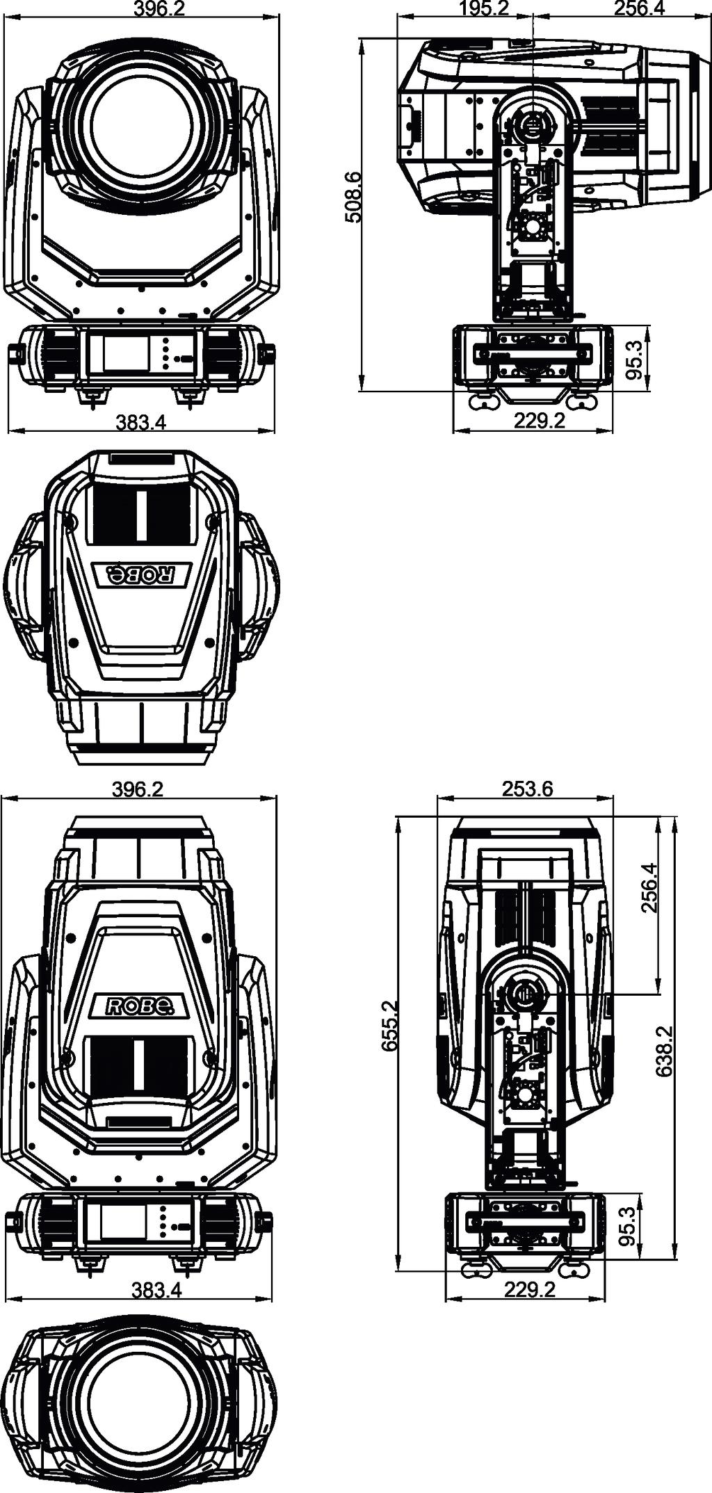
40 Dimensions (mm) 40

41 10. Maintenance and cleaning It is absolutely essential that the fixture is kept clean and that dust, dirt and smoke-fluid residues must not build up on or within the fixture. Otherwise, the fixture s light output will be significantly reduced. Regular cleaning will not only ensure the maximum light output, but will also allow the fixture to function reliably throughout its life. A soft lint-free cloth moistened with any good glass cleaning fluid is recommended, under no circumstances should alcohol or solvents be used! DANGER! Always disconnect the fixture from mains before starting any maintenance work. If the fixture is connected to mains, high voltage is present at a heat sink and some parts of the lamp driver in the fixture head! Lamp driver and its heat sink is under high voltage! The front objective lens will require weekly cleaning as smoke-fluid tends to building up residues, reducing the lightoutput very quickly. The cooling-fans should be cleaned monthly. The interior of the fixture should be cleaned at least annually using a vacuum-cleaner or an air-jet. Dichroic colour filters and gobo wheels and the internal lenses should be cleaned monthly. Remove dust and dirt from the fans and cooling vents using a soft brush and vacuum-cleaner. Important! Check the air filters periodically and clean before they become clogged! Clean the air filters placed in the fixture head and base. Use a vacuum cleaner, compressed air or you can wash them and put back dry. After replacing the air filters, reset the elapsed time counter in the menu "Information" (Information--->Air Filters---> Elapsed Time). Replacing the fuse. Before replacing the fuse, unplug mains lead. 1) Remove the fuse holder on the rear panel of the base with a fitting screwdriver from the housing (anti-clockwise). 2) Remove the old fuse from the fuse holder. 3) Install the new fuse in the fuse holder (only the same type and rating). 4) Replace the fuseholder in the housing and fix it. 41
Robin BMFL Spot. Table of contents
 1 Version 1.7 Robin BMFL Spot Table of contents 1. Safety instructions... 3 2. Operating determination... 4 3. Fixture exterior view... 5 4. Installation... 6 4.1 Connection to the mains... 6 4.2 Installing
Robin BMFL Blade. Table of contents
 1 Version 1.7 Robin BMFL Blade Table of contents 1. Safety instructions... 3 2. Operating determination... 4 3. Fixture exterior view... 5 4. Installation... 6 4.1 Connection to the mains... 6 4.2 Installing
Robin DL4X. Table of contents
 Version1.0 Robin DL4X Table of contents 1. Safety instructions... 3 2. Operating determination... 4 3. Fixture exterior view... 5 4. Installation... 6 4.1 Connection to the mains... 6 4.2 Replacing gobos...
Robin DL4S Profile. Table of contents
 1 Version1.3 Robin DL4S Profile Table of contents 1. Safety instructions... 3 2. Operating determination... 4 3. Fixture exterior view... 5 4. Installation... 6 4.1 Connection to the mains... 6 4.2 Replacing
Robin DL7S Profile. Table of contents
 1 Version 2.1 Robin DL7S Profile Table of contents 1. Safety instructions... 3 2. Operating determination... 4 3. Fixture exterior view... 5 4. Installation... 6 4.1 Connection to the mains... 6 4.2 Replacing
Robin MMX Spot. Table of contents
 1 Version 2.2 Robin MMX Spot Table of contents 1. Safety instructions... 3 2. Operating determination... 4 3. Fixture exterior view... 5 4. Installation... 6 4.1 Connection to the mains... 6 4.2 Installing
Robin Viva. Table of contents
 1 Version 1.4 Robin Viva Table of contents 1. Safety instructions... 3 2. Operating determination... 4 3. Fixture exterior view... 5 4. Installation... 6 4.1 Connection to the mains... 6 4.2 Replacing
USER MANUAL. DE-1 Police-light. CAUTION! Keep this device away from rain and moisture! Unplug mains lead before opening the housing!
 USER MANUAL DE-1 Police-light CAUTION! Keep this device away from rain and moisture! Unplug mains lead before opening the housing! For your own safety, please read this user manual carefully before you
LED Thunder S-150 Code 1097
 LED Thunder S-150 Code 1097 User Manual 1 1 SAFETY INSTRUCTIONS This device has left the factory in perfect condition. In order to maintain this condition and to ensure a safe operation, it is absolutely
Fixture One XLR Signal Cable One Omega Clamp - Two Safety Chain One User Manual - One
 TABLE OF CONTENTS 1. INTRODUCTION AND UNPACKING 1 2. SAFTEY INSTRUCTIONS 1-2 3. OPERATION INSTRUCTIONS 2-3 4. MOUNTING AND INSTALLATION 3-4 5. DMX-512 CONTROL CONNECTIONS 4-5 6. MENU NAVIGATION 5 7. PHOTOMETRIC
User Manual. 360W LED Moving Zoom KEEP THIS MANUAL FOR FUTURE NEEDS. 36pcs10W 4 in 1 RGBW LEDs
 User Manual 360W LED Moving Zoom 36pcs10W 4 in 1 RGBW LEDs KEEP THIS MANUAL FOR FUTURE NEEDS 1. Dispacking Thank you for choosing our moving head. For your own safety, please read this manual before installing
LED Spot 300W. Please read this user manual before your operation
 LED Spot 300W Please read this user manual before your operation 1. Introduction 2. General Guideline 3. Safety Instructions 4. Cleaning and Maintenance 5. Technical Parameters 6. DMX Channels 7. Remark
LED Beam Moving Head. TWIST-150LED Order No INSTRUCTION MANUAL
 LED Beam Moving Head TWIST-150LED Order No. 38.7970 INSTRUCTION MANUAL MONACOR INTERNATIONAL GmbH & Co. KG Zum Falsch 36 28307 Bremen Germany www.monacor.com 01.30.11.2016 ELECTRONICS FOR SPECIALISTS ELECTRONICS
USER MANUAL. TS-3 DMX-Scanner. For your own safety, please read this user manual carefully before you initial start-up.
 USER MANUAL TS- DMX-Scanner For your own safety, please read this user manual carefully before you initial start-up. Every person involved with the installation, operation and maintenance of this device
BEAM MOVING HEAD WITH 100W OSRAM HRI LAMP AND 8-FACET PRISM USER GUIDE
 BEAM MOVING HEAD WITH 100W OSRAM HRI LAMP AND 8-FACET PRISM USER GUIDE 10410 - Version 1 / 11-2015 English Ray1R - Beam moving head with 100W OSRAM HRI LAMP and 8-facet prism 1 - Safety information Important
aorun manual V2.0 MARCH 2018
 aorun manual V2.0 MARCH 2018 table of CONTENTS Dimensions 2 Safety instruction 5 Physical installation 6 Control panel 8 Menu navigation 9 DMX Protocols 12 DMX protocol CH14 12 DMX protocol CH16 15 DMX
ALO 030 MKII. 30 Watt DMX LED scanner. User manual
 ALO 030 MKII 30 Watt DMX LED scanner User manual Safety instructions WARNING! Always keep this device away from moisture and rain! Hazardous electrical shocks may occur! WARNING! Only connect this device
BEAM MOVING HEAD YODN Lamp. 132W 2R MOVING HEAD Brightness / Stability USER MANUAL. Version 1.0 beta
 BEAM MOVING HEAD YODN Lamp W R MOVING HEAD Brightness / Stability This product manual contains important information about the safe installation and use of this projector. Please read and follow these
Robin 600 PureWhite. Robin 600 PureWhite WirelessDMX. (WarmWhite/CoolWhite) Table of contents
 Table of contents") Version1.2 Robin 600 PureWhite Robin 600 PureWhite WirelessDMX (WarmWhite/CoolWhite) Table of contents 1. Safety instructions... 3 2. Fixture exterior view... 5 3. Installation... 6 3.1 Connection to the
Version1.2 Robin 600 PureWhite Robin 600 PureWhite WirelessDMX (WarmWhite/CoolWhite) Table of contents 1. Safety instructions... 3 2. Fixture exterior view... 5 3. Installation... 6 3.1 Connection to the
LED SPOT HEAD USERS GUIDE
 LED SPOT HEAD USERS GUIDE 1 1. Product Introduction: 1.1 Before unpack the fixture, pls make sure that the packing is in good condition, following items will be found in the box: - The fixture - This users
ORLAND SCAN PR PR LIGHTING LTD. Yingbin Road, Dashi Panyu, Guangzhou, China
 ORLAND SCAN PR-1201 This product manual contains important information about the safe installation and use of this projector. Please read and follow these instructions carefully and keep this manual in
LED SPOT HEAD USERS GUIDE
 LED SPOT HEAD USERS GUIDE 1. Product Introduction: 1 1.1 Before unpack the fixture, pls make sure that the packing is in good condition, following items will be found in the box: -The fixture -This users
Robin 600 LEDWash. Table of contents
 Version1.3 Robin 600 LEDWash Table of contents 1. Safety instructions... 3 2. Fixture exterior view... 5 3. Installation... 6 3.1 Connection to the mains... 6 3.2 Rigging the fixture... 7 3.3 DMX-512 connection...
AuraBeam 150 LED. User Manual KEEP THIS MANUAL FOR FUTURE NEEDS
 AuraBeam 150 LED LED 0.2m ta 40 C tc 150 C User Manual KEEP THIS MANUAL FOR FUTURE NEEDS 1 SAFETY INSTRUCTIONS CAUTION Becareful with your operations.with a dangerous voltage you cansuffer a dangerous
Dragonfly Quad. User Manual V1.4. Order code: EQLED101
 Dragonfly Quad User Manual V1.4 Order code: EQLED101 Safety advice WARNING FOR YOUR OWN SAFETY, PLEASE READ THIS USER MANUAL CAREFULLY BEFORE YOUR INITIAL START-UP! Before your initial start-up, please
PRODUCT SPECIFICATIONS
 FOS Beam 150W 1 PRODUCT SPECIFICATIONS TECHNICAL SPECIFICATION Voltage: 100/240 Volt AC, 50/60 Hz. Power Consumption: 250 Watt. Light Source: 150 Watt LED, 6800K Beam angle: 2 Colors: 11 dichroic color
aorun manual V1.0 OCTOBER 2017
 aorun manual V1.0 OCTOBER 2017 table of CONTENTS Dimensions 2 Safety information 5 Specifications 7 Included items 8 Physical installation 9 Control panel 11 Operating instructions 12 Channel function
DJ SCAN 150 XT. Table of contents
 DJ SCAN 150 XT Table of contents 1. Safety instructions... 3 2. Operating determinations... 4 3. Description of the device... 5 4. Installation... 6 4.1Fitting/Exchanging the lamp... 6 4.2 Rigging the
BSL HELIOS USERS GUIDE
 BSL HELIOS USERS GUIDE 1. Product Introduction: 1.1 Before unpack the fixture, pls make sure that the packing is in good condition, following items will be found in the box: - The fixture - This users
minipointe is a tiny agile air cutter specifically designed to produce sharp beam and aerial effects especially in venues constrained by size.
 minipointe is a tiny agile air cutter specifically designed to produce sharp beam and aerial effects especially in venues constrained by size. Striking bright 0 parallel beams with glowing colours and
User Manual MAINTENANCE AND CLEANING. CAUTION Disconnect from mains before starting maintenance operation. KEEP THIS MANUAL FOR FUTURE NEEDS
 0 MAINTENANCE AND CLEANING The following points have to be considered during the inspection: ) All screws for installing the devices or parts of the device have to be tightly connected and must not be
ArtFox Lighting. LED Beam Wash 19E. User manual. 6. Fixture Cleaning. Please read the instructions carefully before use
 6. Fixture Cleaning ArtFox Lighting LED Beam Wash 19E The cleaning of internal and external optical lenses and/or mirrors must be carried out periodically to optimize light output. Cleaning frequency depends
PRODUCT SPECIFICATIONS
 FOS Spot 150W 1 PRODUCT SPECIFICATIONS TECHNICAL SPECIFICATION Voltage: 100/240 Volt AC, 50/60 Hz. Power Consumption: 250 Watt. Light Source: 150 Watt LEDs, 7500K. Beam angle: 14. Colors: 8 colors + White
Fusion 120 Zoom. User Manual. Order code: EQLED068
 Fusion 120 Zoom User Manual Order code: EQLED068 Safety advice WARNING FOR YOUR OWN SAFETY, PLEASE READ THIS USER MANUAL CAREFULLY BEFORE YOUR INITIAL START-UP! Before your initial start-up, please make
This device is a lighting effect for professional use on stages, in discotheques, theatres, etc..
 At first, thank you for purchasing QUADRO 24. For the sake of safety and regular operation of this projector, please read this manual carefully before using and operating it, lest incur any personal injury
PROFESSIONAL SCANNER USER S MANUAL
 PROFESSIONAL SCANNER USER S MANUAL (VER1.0) KEEP THIS MANUAL FOR FUTURE NEEDS For your own safety, please read this user manual carefully before installing the device. K eep thi s devi ce aw ay f rom rai
HEX16 Strip User Manual
 User Manual www.showtech.com.au 1 Table of Contents 1. Safety instructions 3 1.1 Overhead rigging.4 1.2 Power Connection..5 1.3 Cleaning and Maintenance..6 2. Menu Navigation..7 3. DMX Allocation..9 4.
Stratos Duo RGB. User Manual. Order code: EQLED371
 Stratos Duo RGB User Manual Order code: EQLED1 Safety advice WARNING FOR YOUR OWN SAFETY, PLEASE READ THIS USER MANUAL CAREFULLY BEFORE YOUR INITIAL START-UP! Before your initial start-up, please make
TRANSCENSION 6-CHANNEL DMX DIMMER PACK (order code: BOTE40) USER MANUAL
 USER MANUAL") www.prolight.co.uk TRANSCENSION 6-CHANNEL PACK (order code: BOTE40) USER MANUAL SAFETY WARNING FOR YOUR OWN SAFETY, PLEASE READ THIS USER MANUAL CAREFULLY BEFORE YOUR INITIAL START-UP! CAUTION! Keep this
www.prolight.co.uk TRANSCENSION 6-CHANNEL PACK (order code: BOTE40) USER MANUAL SAFETY WARNING FOR YOUR OWN SAFETY, PLEASE READ THIS USER MANUAL CAREFULLY BEFORE YOUR INITIAL START-UP! CAUTION! Keep this
KEEP THIS MANUAL FOR FUTURE NEEDS
 USER S MANUAL www.lfxgroup.com MOVING HEAD PRO HEAD 250 KEEP THIS MANUAL FOR FUTURE NEEDS For your own safety, please read this user manual carefully before installing the device. Keep this device away
Instruction Manual. from software version 1.0 (instruction version 1.3) Internet:
 Internet:") Instruction Manual from software version 1.0 (instruction version 1.3) email: service@glp.de Internet: http://www.glp.de GLP German Light Production (V1.3) 1 Table of contents 1 Description of Device...
Instruction Manual from software version 1.0 (instruction version 1.3) email: service@glp.de Internet: http://www.glp.de GLP German Light Production (V1.3) 1 Table of contents 1 Description of Device...
DMX Operator 192-channel lighting controller
 USER MANUAL DMX Operator 192-channel lighting controller CAUTION! Keep this device away from rain and moisture! Unplug mains lead before opening the housing! For your own safety, please read this user
LED BEAM HEAD USERS GUIDE
 LED BEAM HEAD USERS GUIDE 1. Product Introduction: 1.1 Before unpack the fixture, pls make sure that the packing is in good condition, following items will be found in the box: -The fixture -This users
LED Spere Direct Control 30 ORDERCODE 41125
 LED Spere Direct Control 30 ORDERCODE 41125 Congratulations! You have bought a great, innovative product from Showtec. The Showtec LED Sphere Direct Control 30 brings excitement to any venue. Whether you
Spiider THE NEXT BIG THING FROM ROBE!
 Spiider THE NEXT BIG THING FROM ROBE! Spiider, a superbright next generation of LED WashBeam luminaires, using 18x 30 Watt and 1x 60 Watt LEDs and combining it with a very efficient 12,5:1 zoom optical
Commander 384. w w w. p r o l i g h t. c o. u k U S E R M A N U A L
 Commander 384 w w w. p r o l i g h t. c o. u k U S E R M A N U A L 1, Before you begin 1.1: Safety warnings...2 3 1.2: What is included...4 1.3: Unpacking instructions...4 2, Introduction 2.1: Features...4
KingWash 7QX 7x40w,Zoom 5-60degree. User manual. Please read the instructions carefully before use TABLE OF CONTENTS
 KingWash 7QX 7x40w,Zoom 5-60degree User manual Please read the instructions carefully before use TABLE OF CONTENTS 1. Safety Instructions... 2 2. Technical Specifications... 4 3. How To Control The Unit...
www. eklights.com Guangzhou Liangyi Lighting Equipments Co.,Ltd. 37 Gongyedadao, Xinhua, Huadu, Guangzhou PC:510800
 Guangzhou Liangyi Lighting Equipments Co.,Ltd. 37 Gongyedadao, Xinhua, Huadu, Guangzhou PC:510800 Tel: (020)666 090 88-8002 Fax: (020) 868 670 11 www. eklights.com USER MANUAL CONTENTS SAFETY DIMENSION
80W SPOT MOVING HEAD CYCLONE-80 USER GUIDE April 2014 version
 80W SPOT MOVING HEAD CYCLONE-80 USER GUIDE 10175-1 April 2014 version 1 - Safety information Important safety information WARNING : This unit contains no user-serviceable parts. Do not open the housing
EDITION NOTES. Document Revision
 User Manual EDITION NOTES The Maverick MK1 Spot User Manual includes a description, safety precautions, installation, programming, operation and maintenance instructions for the Maverick MK1 Spot as of
USER MANUAL Table of Contents
 USER MANUA Table of Contents Safety Information. 3 Specifications.. 4 Main Power Connection.. 5 DMX-512 Connection...... 5 DMX Profile... 7 Main Control Menu... 8 Rigging the Fixture.10 Cleaning & Maintenance...10
G-SPOT MOVING HEAD PROFILE
 G-SPOT MOVING HEAD PROFILE Dimensions 805 (31.7) 646 (25.4) 327 (12.9) 340 (13.4) 370 (14.6) 494 (19.5) 135 135 821 (32.3) 144 (5.7) Min. c/c 764 (30.0) 470 (18.5) 16 (0.63) 270 270 664 (26.2) 492 (19.4)
MH-X50+ LED spot moving head. user manual
 MH-X50+ LED spot moving head user manual Musikhaus Thomann e.k. Treppendorf 30 96138 Burgebrach Germany Telephone: +49 (0) 9546 9223-0 E-mail: info@thomann.de Internet: www.thomann.de 02.08.2012 Table
WASH MOVING HEAD M7W15RGBW USER MANUAL. For safety, please read this user manual carefully before initial use.
 1 WASH MOVING HEAD M7W15RGBW USER MANUAL For safety, please read this user manual carefully before initial use. Event Lighting reserves the right to revise the manual at any time. Information and specifications
LED Pixel Track V3 ORDERCODE 42200
 LED Pixel Track V3 ORDERCODE 42200 Congratulations! You have bought a great, innovative product from Showtec. The Showtec LED Pixel Track brings excitement to any venue. Whether you want simple plug-&-play
LED PAR 64 floor 12x8W RGBWAUV incl. remote
 Manual LED PAR 64 floor 12x8W RGBWAUV incl. remote Table of contents 1. Safety instructions... 3 1.1. For safe and efficient operation... 3 2. Designated use... 4 2.1. Overhead installation... 5 3. Introduction...
KEEP THIS MANUAL FOR FUTURE NEEDS
 USER S MANUAL www.lfxgroup.com SCANNER SCAN 250 KEEP THIS MANUAL FOR FUTURE NEEDS For your own safety, please read this user manual carefully before installing the device. Keep this device away from rain
JunoScan MK-II LED scanner. user manual
 JunoScan MK-II LED scanner user manual Musikhaus Thomann e.k. Treppendorf 30 96138 Burgebrach Germany Telephone: +49 (0) 9546 9223-0 E-mail: info@thomann.de Internet: www.thomann.de 26.10.2012 Table of
Spectra Batten (Order code: LEDJ95)
") www.prolight.co.uk Spectra Batten (Order code: LEDJ95) Safety WARNING FOR YOUR OWN SAFETY, PLEASE READ THIS USER MANUAL CAREFULLY BEFORE YOUR INITIAL START-UP! CAUTION! Keep this equipment away from rain,
www.prolight.co.uk Spectra Batten (Order code: LEDJ95) Safety WARNING FOR YOUR OWN SAFETY, PLEASE READ THIS USER MANUAL CAREFULLY BEFORE YOUR INITIAL START-UP! CAUTION! Keep this equipment away from rain,
LED Pixel Track Pro ORDERCODE 42205
 LED Pixel Track Pro ORDERCODE 42205 Congratulations! You have bought a great, innovative product from Showtec. The Showtec LED Pixel Track Pro brings excitement to any venue. Whether you want simple plug-&-play
DMX LED light effect with 4 lenses
 DMX LED light effect with 4 lenses User manual 1 Safety precautions WARNING: This unit may cause serious injury to the eyes when used incorrectly. It is therefore strongly advised to read this user manual
LED BEAM HEAD USERS GUIDE
 LED BEAM HEAD USERS GUIDE 1 1. Product Introduction: 1.1 Before unpack the fixture, pls make sure that the packing is in good condition, following items will be found in the box: -The fixture -This users
ORDER CODE: EQLED65 USER MANUAL
 www.prolight.co.uk ORDER CODE: EQLED65 USER MANUAL Safety WARNING FOR YOUR OWN SAFETY, PLEASE READ THIS USER MANUAL CAREFULLY BEFORE YOUR INITIAL START-UP! CAUTION! Keep this equipment away from rain,
LED IP65 Slimline Par RGBWA +UV 7x12W
 VIS0495.4 LED IP65 Slimline Par RGBWA +UV 7x12W User Manual KEEP THIS MANUAL FOR FURTHER NEEDS Key Features: 7 x RGBAW + UV HEX 12W LED IP65 Weatherproof Die-Cast Housing Slimline, Compact & Stylish Design
YOUR OWN SAFETY, PLEASE READ THIS USER MANUAL CAREFULLY BEFORE POWERING OR INSTALLING. SAVE IT FOR FUTURE REFERENCE
 MYTHIC USER S MANUAL Thank you for purchasing our moving head MYTHIC. Every suit has been thoroughly tested and shipped in perfect condition. Carefully check the shipping carton for damage that may have
Spectra Flood Q40. Exterior Fixture User Manual. Order code: LEDJ Version LEDJ284N - 15 Version
 Spectra Flood Q40 Exterior Fixture User Manual Order code: LEDJ284-40 Version LEDJ284N - 15 Version Safety advice WARNING FOR YOUR OWN SAFETY, PLEASE READ THIS USER MANUAL CAREFULLY BEFORE YOUR INITIAL
DJ SCAN 250 XT. Table of contents
 DJ SCAN 250 XT Table of contents 1. Safety instructions... 3 2. Operating determinations... 4 3. Description of the device... 5 4. Installation... 6 4.1Fitting/Exchanging the lamp... 6 4.2 Inserting/Exchanging
MB150 USER MANUAL (V2.00) Elektralite 70 Sea Lane, Farmingdale N.Y U.S.A. Tel (+1) Fax (+1)
 Elektralite 70 Sea Lane, Farmingdale N.Y U.S.A. Tel (+1) Fax (+1)") MB150 USER MANUAL (V2.00) Elektralite 70 Sea Lane, Farmingdale N.Y. 11735 U.S.A. Tel (+1)-516-249-3662 Fax (+1)-516-249-8870 www.myelektralite.com For your own safety, please read this user manual carefully
MB150 USER MANUAL (V2.00) Elektralite 70 Sea Lane, Farmingdale N.Y. 11735 U.S.A. Tel (+1)-516-249-3662 Fax (+1)-516-249-8870 www.myelektralite.com For your own safety, please read this user manual carefully
Hex-color RGBAW+UV LED strip light
 Hex-color RGBAW+UV LED strip light 2 19 SAFETY / GENERAL INSTRUCTIONS INTRODUCTION Features Specifications OVERVIEW : CONNECTIONS Rear view DIMENSIONS INSTALLATION Mounting FUNCTIONS AND SETTINGS Function
USER MANUAL Table of Contents
 USER MANUAL Table of Contents Safety Information. 3 Specifications.. 4 Main Power Connection.. 5 DMX-512 Connection...... 5 Main Control Menu... 6 Fixture Addressing... 6 Manual Mode...7 Save Scene...7
PRODUCT SPECIFICATIONS
 FOS RGB Fan 1 PRODUCT SPECIFICATIONS TECHNICAL SPECIFICATION Voltage: 110/240 Volt AC, 50/60 Hz. Power Consumption: 180 Watt. Light Source: 792x 0,2 Watt RGB SMD 5050 LEDs. Effects: LEDs are separated
PROFESSIONAL MOVING HEAD USER S MANUAL DESIGN WASH 250
 PROFESSIONAL MOVING HEAD USER S MANUAL DESIGN WASH 250 KEEP THIS MANUAL FOR FUTURE NEEDS For your own safety, please read this user manual carefully before installing the device. K eep thi s devi ce aw
2002 Martin Professional A/S, Denmark.
 Freekie user manual 2002 Martin Professional A/S, Denmark. All rights reserved. No part of this manual may be reproduced, in any form or by any means, without permission in writing from Martin Professional
SUPER LED F4.7 VW Vari-White INSTRUCTION MANUAL
 SUPER LED F4.7 VW Vari-White 60W Vari-White from 2.750 to 6.900 K - Enhanced CRI > 94 White light, with Adjustable Correlated Colour Temperature INSTRUCTION MANUAL Operated Pole Operated MANUFACTURER REPRESENTATIVE
LED Spot Light User Manual Model LS90 Big Dipper Laser Science And Technology Co., Ltd Please read this manual carefully before operating
 LED Spot Light User Manual Model:LS90 Big Dipper Laser Science And Technology Co., Ltd REV: 1.01 Please read this manual carefully before operating Warnings: Please check the package whether any damage
Mover Beam 7 CKU (US) / CKE (EU) USER MANUAL
 / CKE (EU) USER MANUAL") Mover Beam 7 CKU01-5030 (US) / CKE01-5030 (EU) USER MANUAL Introduction Thank you for purchasing the ColorKey Mover Beam 7. Please read these instructions carefully before use. Operating this fixture according
Mover Beam 7 CKU01-5030 (US) / CKE01-5030 (EU) USER MANUAL Introduction Thank you for purchasing the ColorKey Mover Beam 7. Please read these instructions carefully before use. Operating this fixture according
ALO 060 DMX LED scanner
 ALO 060 DMX LED scanner User manual Safety instructions WARNING! Always keep this device away from moisture and rain! Hazardous electrical shocks may occur! WARNING! Only connect this device to a matching
Color Ground 12T 16 A USER MANUAL 5 APPENDIX 5.1 TROUBLE SHOOTING 5.2 MAINTENANCE LED MODULE. Version 1.0 SITUATION CAUSE ACTION 5 APPENDIX
 5 APPENDIX 5. TROUBLE SHOOTING LED MODULE SITUATION CAUSE ACTION Can not receive DMX signal ) DMX signal cable error 2) Signal connection error 3) The input signal IC damaged 4) DMX address error ) Check
PicoSpot 20 LED moving head. user manual
 PicoSpot 20 LED moving head user manual Musikhaus Thomann Thomann GmbH Hans-Thomann-Straße 1 96138 Burgebrach Germany Telephone: +49 (0) 9546 9223-0 E-mail: info@thomann.de Internet: www.thomann.de 25.01.2017,
180w led gobo moving USER MANUAL
 180w led gobo moving USER MANUAL 1. BEFORE YOU BEGIN What is included 1 x Light 1 x Mounting bracket and screws 1 x Power cable 1 x User Manual Unpacking Instructions Congratulations on purchasing ART-TECH
6X3W RGB LEDS PROJECTOR FOR PROFESSIONAL TRUSSES USER GUIDE / Version 1
 6X3W RGB LEDS PROJECTOR FOR PROFESSIONAL TRUSSES USER GUIDE 10364-07-2015 / Version 1 English MINITRUSS-6TCb - 6x3W RGB LEDs projector for professional trusses 2 MINITRUSS-6TCb - 6x3W RGB LEDs projector
LED Floodlight 6x 1W, 40 ORDERCODE ORDERCODE ORDERCODE ORDERCODE ORDERCODE ORDERCODE 42760
 LED Floodlight 6x 1W, 40 ORDERCODE 42755 ORDERCODE 42756 ORDERCODE 42757 ORDERCODE 42758 ORDERCODE 42759 ORDERCODE 42760 Congratulations! You have bought a great, innovative product from Showtec. The Showtec
PART 1 PRODUCT (GENERAL)...1.
...1.") TABLE OF CONTENTS PART PRODUCT (GENERAL)....-- TECHNICAL SPECIFICATIONS....-- SAFETY WARNING... PART INSTALLATION....--MOUNTING....--SIGNAL CONNECTIONS.......--SETTING UP WITH A DMX5 CONTROLLER(STAGE MODE)...
TABLE OF CONTENTS PART PRODUCT (GENERAL)....-- TECHNICAL SPECIFICATIONS....-- SAFETY WARNING... PART INSTALLATION....--MOUNTING....--SIGNAL CONNECTIONS.......--SETTING UP WITH A DMX5 CONTROLLER(STAGE MODE)...
BEAM 200. User Manual
 BEAM 200 User Manual Catalogue 1 Open-package inspection ----------------------------------------------------------------------page2 2 Attentions-----------------------------------------------------------------------------------------page2
BSL MAGIC ZOOM 7 USERS GUIDE
 BSL MAGIC ZOOM 7 USERS GUIDE 1 1. Product Introduction: 1.1 Before unpack the fixture, pls make sure that the packing is in good condition, following items will be found in the box: -The fixture -This
LED Par 56 Short Eco V2 ORDERCODE 42417
 LED Par 56 Short Eco V2 ORDERCODE 42417 Congratulations! You have bought a great, innovative product from Showtec. The Showtec LED Par 56 brings excitement to any venue. Whether you want simple plug-&-play
USER GUIDE 8-CHANNEL DMX CONTROLLER December 2013 Version 1.0 CHASE / STROBE SPEED FADE SPEED RED GREEN BLUE WHITE AMBER DIMMER INSERT
 8-CHANNEL DMX CONTROLLER RED GREEN BLUE YELLOW 1 2 3 4 5 6 CYAN ORANGE PURPLE WHITE RED GREEN BLUE WHITE AMBER DIMMER RECORD INSERT DELETE TAP CLEAR MANUAL MUSIC 1 2 3 5 6 7 AUTO CHASE / STROBE SPEED 4
PLL2210MW LED Monitor
 PLL2210MW LED Monitor USER'S GUIDE www.planar.com Content Operation Instructions...1 Safety Precautions...2 First Setup...3 Front View of the Product...4 Rear View of the Product...5 Quick Installation...6
LED MOVING HEAD LedWash. 36 x 10w RGBW 4in1 Zooming USER MANUAL. Version 1.0 beta
 LED MOVING HEAD LedWash x 10w RGBW in1 Zooming This product manual contains important information about the safe installation and use of this projector. Please read and follow these instructions carefully
Mini LED Pin Spot Light Model: PLS00571
 Mini LED Pin Spot Light Model: PLS00571 1 Please read these instructions carefully before use and retain for future reference. IMPORTANT SAFETY INFORMATION When using electrical appliances basic safety
Design Spot 575E. Elation Professional 4295 Charter Street Los Angeles, Ca Rev. 7/24/07
 Design Spot 575E Elation Professional 4295 Charter Street Los Angeles, Ca 90058 www.elationlighting.com Rev. 7/24/07 Contents 1. General Information 3 a. Introduction. 3 b. Unpacking.... 3 c. Customer
Winmate Communication INC.
 20.1 Military Grade Display Model: R20L100-RKA2ML User s Manual Winmate Communication INC. May, 2011 1 IMPORTANT SAFETY INSTRUCTIONS Please read these instructions carefully before using the product and
SHOWLINE SL BEAM 100 LED LUMINAIRE SPECIFICATIONS.
 SHOWLINE SL BEAM 100 LED LUMINAIRE SPECIFICATIONS. GENERAL. A.) Overview. 1.) The luminaire shall be a motorized colour mixing luminaire employing seven (7) homogenized red, green, blue, and white LED
Edition Notes. Edition Notes. Trademarks CHAUVET, the Chauvet logo and Maverick MK1 Hybrid are registered trademarks or
 User Manual Edition Notes Edition Notes The Maverick MK1 Hybrid User Manual Rev. 1 covers the description, safety precautions, installation, programming, operation, and maintenance of the Maverick MK1
Part names (continued) Remote control
 Remote control") Introduction Part names (continued) Remote control (1) STANDBY ( 25) (1) (2) ON ( 25) (3) (3) ID - 1 / 2 / 3 / 4 s ( 18) (4) (4) COMPUTER 1 ( 27) (7) (5) COMPUTER 2 * (8) (6) COMPUTER 3 * (10) (13) (7)
Introduction Part names (continued) Remote control (1) STANDBY ( 25) (1) (2) ON ( 25) (3) (3) ID - 1 / 2 / 3 / 4 s ( 18) (4) (4) COMPUTER 1 ( 27) (7) (5) COMPUTER 2 * (8) (6) COMPUTER 3 * (10) (13) (7)
USER MANUAL Table of Contents
 USER MANUA Table of Contents Safety Information.. 3 Specifications.. 4 Main Power Connection.. 5 DMX-512 Connection... 5 Main Control Menu... 6 DMX Profile... 8 Rigging the Fixture....10 Cleaning & Maintenance...10
Stage Wash 7x 10W LED Moving Head (RGBW)
") Stage Wash 7x 10W LED Moving Head (RGBW) P/N 612870 User's Manual CONTENTS SAFETY WARNINGS AND GUIDELINES... 3 INTRODUCTION... 4 FEATURES... 5 CUSTOMER SERVICE... 5 PACKAGE CONTENTS... 6 PRODUCT OVERVIEW...
Stage Wash 7x 10W LED Moving Head (RGBW) P/N 612870 User's Manual CONTENTS SAFETY WARNINGS AND GUIDELINES... 3 INTRODUCTION... 4 FEATURES... 5 CUSTOMER SERVICE... 5 PACKAGE CONTENTS... 6 PRODUCT OVERVIEW...
Design Spot 575E. Elation Professional 6122 S. Eastern Ave Los Angeles, Ca
 Design Spot 575E Elation Professional 6122 S. Eastern Ave Los Angeles, Ca. 90040 Rev. 05/15/2008 Elation Professional 2 Design Spot 575E Design Spot 575E CONTENTS 1. General Information 4 a. Introduction.
PL2410W LCD Monitor USER'S GUIDE.
 PL2410W LCD Monitor USER'S GUIDE www.planar.com Content Operation Instructions...1 Safety Precautions...2 First Setup...3 Front View of the Product...4 Rear View of the Product...5 Quick Installation...6
Quick Reference Guide
 Quick Reference Guide About this Guide Disclaimer The Q-Wash 360Z-LED Quick Reference Guide (QRG) only contains the product s connection and mounting information as well as the menu options and the DMX