3 ARCADE. Figure 3-1: FIRST POWER UP SM playing area. Section 3 ARCADE V5 15 of 129
|
|
|
- Mitchell Richardson
- 6 years ago
- Views:
Transcription

1 3 ARCADE Figure 3-1: FIRST POWER UP SM playing area The ARCADE includes all elements of the game infrastructure that are required to play FIRST POWER UP SM : the FIELD, SWITCHES, the SCALE, VAULTS, carpet, the POWER CUBES, and all equipment needed for FIELD control, ROBOT control, and scorekeeping. The competition ARCADE is modular and assembled, used, disassembled, and shipped many times during the competition season. It will undergo wear and tear. The ARCADE is designed to withstand rigorous play and frequent shipping. Every effort is made to ensure that ARCADES are consistent from event to event. However, ARCADES are assembled in different venues by different event staff and some small variations occur. For details regarding assembly tolerances, please refer to the 2018 ARCADE Layout and Marking Drawing. Successful Teams will design ROBOTS that are insensitive to these variations. Illustrations included in this section are for a general visual understanding of the FIRST POWER UP SM ARCADE, and dimensions included in the manual are nominal. Please refer to the official drawings for exact dimensions, tolerances, and construction details. The official drawings, CAD models, and drawings for low-cost versions of important elements of the FIRST POWER UP SM FIELD are posted on the 2018 FIRST POWER UP SM Game & Season Materials page on the FIRST website. V5 15 of 129
2 3.1 Zones and Markings ALLIANCE STATION: a 22 ft. (~671 cm) wide by 10 ft. (~305 cm) deep by 10 ft. (~305 cm) tall volume formed by, and including three (3) PLAYER STATIONS, an EXCHANGE wall, and 2 in. ALLIANCE colored gaffers tape. AUTO LINE: a line of 2 in. (~5 cm), black gaffers tape that is the width of the FIELD and is 10 ft. (~305 cm) from each ALLIANCE WALL to the leading edge of the tape. EXCHANGE ZONE: A rectangular area 4 ft. (~122 cm) wide by 3 ft. (~91 cm) deep and infinitely tall volume bounded by the EXCHANGE wall and 2 in. (~5 cm) ALLIANCE colored gaffers tape. The EXCHANGE ZONE includes the tape, but excludes the wall. NULL TERRITORY: one of two, 7 ft. 11 ¼ in. (~242 cm) wide by 6 ft. (~183 cm) deep and infinitely tall volumes formed by 2 in. (~5 cm), white gaffers tape and the GUARDRAILS. The NULL TERRITORY includes the gaffers tape, but excludes the GUARDRAILS. The ALLIANCE S NULL TERRITORY for a MATCH corresponds to the SCALE PLATE color in that NULL TERRITORY and does not change when the FORCE POWER UP is played. PLATFORM ZONE: a 11 ft. 1 ½ in. (~339 cm) wide by 9 ft. 11 ¾ in. (~304 cm) deep and infinitely tall volume bounded by 2 in. (~5 cm) ALLIANCE colored gaffers tape, the faces of the OUTRIGGERS, TOWER, and the SWITCH. The PLATFORM ZONE includes the gaffers tape, but excludes the SWITCH and the faces of the OUTRIGGERS AND TOWER. PORTAL: a 4 ft. (~122 cm) wide by 12 ft. 11 in. (~394 cm) deep infinitely tall volume bounded by, and including, 2 in. (~5 cm). ALLIANCE colored gaffers tape and the PORTAL wall. POWER CUBE ZONE: A rectangular area 3 ft. 9 in. (~114 cm) wide by 3 ft. 6 in. (~107 cm) deep, bounded by the SWITCH and 2 in. (~5 cm) ALLIANCE colored gaffers tape. The POWER CUBE ZONE includes the gaffers tape, but excludes the SWITCH. STARTING LINE: a line of 2 in. (~5 cm), white gaffers tape that runs the width of the carpet and is 2 ft. 6 in. (~76 cm) behind the ALLIANCE WALL diamond plate, which includes the tape. Figure 3-2: Zones and Markings V5 16 of 129
 carpeted area, bound by and including the inward-facing surfaces of the GUARDRAILS, PORTALS, EXCHANGE walls and ALLIANCE WALLS.")
3 3.2 FIELD The FIELD for FIRST POWER UP SM is a 27 ft. (~823 cm) by 54 ft. (~1646 cm) carpeted area, bound by and including the inward-facing surfaces of the GUARDRAILS, PORTALS, EXCHANGE walls and ALLIANCE WALLS. The carpet used for the FIELD is gray in color (Shaw Floors, Philadelphia Commercial, Neyland II 20, Ground Pepper ). There are two versions of GUARDRAILS and PLAYER STATIONS used for competitions. One design has been used at FIRST Robotics Competitions for several years and matches the 2018 Official FIRST Field Drawings & Models. The other is designed and sold by AndyMark. While the designs are slightly different, the critical dimensions, performance, and expected user experience between the two are the same. Detailed drawings for the AndyMark design are posted on the AndyMark website. All illustrations in the Game Manual show the traditional FIELD design. GUARDRAIL The GUARDRAIL is a system that consists of transparent polycarbonate supported on the top and bottom by aluminum extrusion. The GUARDRAIL prevents ROBOTS from inadvertently exiting the FIELD during a MATCH. There are four (4) gates in the GUARDRAIL that allow access to the FIELD for placement and removal of ROBOTS. The gates are 3 ft. 2 in. (~97 cm) wide and closed and shielded during the MATCH. Figure 3-3: Gate locations V5 17 of 129

 wide and ¾ in.")
.")
 The BRICKS are graphics")
4 3.3 SCALE There is one (1) SCALE centered in the field, and oriented so that the SCALE arm is parallel to the ALLIANCE WALL. The SCALE features an arm, RUNGS, PLATES, OUTRIGGERS, PLATFORMS, and TOWER. All frame surfaces are covered in polycarbonate panels. A cable protector extends from the center of each side of the PLATFORM and is 2 ½ in. (~6 cm) wide and ¾ in. (~2 cm) high (Electriduct, Inc. CSX-3, black). The cable protector is attached to the field with hook fastener, increasing the height to approximately ⅞ in. (~2 cm). These cable protectors extend to the GUARDRAILS and the SWITCHES. Figure 3-4: The SCALE (Note, cable protectors are shown, but are not part of the SCALE) The BRICKS are graphics depicting golden squares surrounded by a black outline that extends 12 in. (~30cm) above the horizontal surface of the PLATFORM. The BRICKS cover the polycarbonate panels at the base of the TOWER and OUTRIGGERS. Figure 3-5: The BRICKS V5 18 of 129
 above the PLATE surface.")
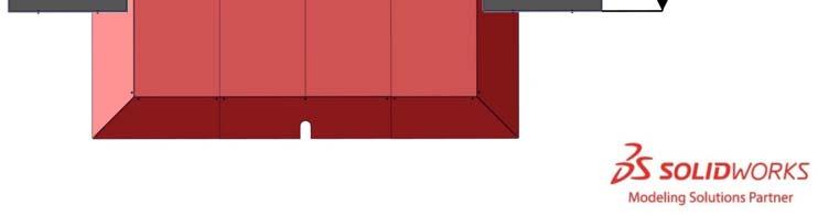
5 SCALE PLATES Each SCALE features two (2) PLATES which are 3 ft. (~91 cm) wide and 4 ft. (~122 cm) deep. The outside edges of the two PLATES are 15 ft. (~457 cm) apart. Each PLATE has four polycarbonate walls which contain Philips Color Kinetics LED lights. The wall closest to the center of the FIELD extends 1 ft. 3 in. (~38 cm) above the PLATE surface. The other walls extend up 3 ½ in (~9 cm) above the PLATE surface. At the start of the MATCH the PLATES are even, such that the outside edges of each PLATE are 5 ft. (~152 cm) +/- 1 in. (~2.5 cm) above the FIELD carpet. The SCALE can tilt and rest in different positions depending on the number and location of the POWER CUBES on the PLATES. During the MATCH, the SCALE is in one of three (3) states based on the magnitude of its tilt: 1. OWNERSHIP by the Red ALLIANCE, or 2. OWNERSHIP by the Blue ALLIANCE, or 3. neither ALLIANCE has OWNERSHIP If the outside edge of an ALLIANCE colored PLATE is positioned between 4 ft. (~122 cm) and 4 ft. 8 in. (~142 cm) above the FIELD carpet then the ALLIANCE has OWNERSHIP of the SCALE. If the outside edge of an alliance colored PLATE is positioned between 5 ft. 4 in. (~163 cm) and 6 ft. (~182 cm) above the FIELD carpet then the opposing ALLIANCE has OWNERSHIP. When neither ALLIANCE has OWNERSHIP of the SCALE, the outside edges of the PLATES are between 5 ft. 4 in. (~163 cm) and 4 ft. 8 in. (~142 cm) above the FIELD carpet. See Figure 3-6. The time required to move between states is dependent on the weight difference and the distribution of the weight on the SCALE PLATES. Details on OWNERSHIP can be found in Section 4.2 Scoring. Figure 3-6: SCALE range of motion Note: It s possible to have the same quantity of POWER CUBES on the PLATES on each side of the SCALE and have the SCALE not be balanced. The location of the POWER CUBES on the SCALE/SWITCH is a factor in its position. V5 19 of 129


6 Figure 3-7: SCALE PLATE dimensions Figure 3-8: SCALE PLATE wall dimensions V5 20 of 129
 long 1 ¼ in.")
 from the carpet to the top of the RUNG.")


7 RUNGS At the top of each SCALE there are two RUNGS, one per ALLIANCE. An ALLIANCE S RUNG extends into their PLATFORM ZONE. RUNGS consist of a 1 ft. 1 in. (~33 cm) long 1 ¼ in. Schedule 40 aluminum pipe supported by 2 in. (~5 cm) box tubing. Each RUNG extends 8 ¼ in. (~21 cm). from the vertical face of the SCALE supports and 7 ft. (~213 cm) from the carpet to the top of the RUNG. The RUNG in Figure 3-9 is highlighted for clarity. Figure 3-9: RUNGS OUTRIGGERS The OUTRIGGERS are supports for the TOWER constructed from aluminum shielded by polycarbonate TOWER The TOWER is the central structure of the SCALE constructed from aluminum shielded by polycarbonate which supports the RUNGS and SCALE PLATES. The tower is 17 in. (~43 cm) wide and extends 2 in. (~5 cm) from the face of the OUTRIGGERS. Figure 3-10: Tower dimensions V5 21 of 129

 wide by 3 ft. 5 ¼ in.")


8 PLATFORM Located at the base of the SCALE, on each side, is a PLATFORM covered with ALLIANCE colored HDPE. The TOWER and OUTRIGGERS separate one PLATFORM from the other. Each PLATFORM top is 8 ft. 8 in. (~264 cm) wide by 3 ft. 5 ¼ in. (~105 cm) deep and 3 ½ in. (~9 cm) tall. The PLATFORM includes ramps which are 1 ft. 1 in. (~33 cm) long with a deg. angle. The ALLIANCE colored tape that abuts the PLATFORM ramps is part of the PLATFORM. Figure 3-11: PLATFORM top length and width dimensions Figure 3-12: PLATFORM height and ramp dimensions V5 22 of 129
 from the ALLIANCE STATION. Each SWITCH is surrounded by a FENCE. An ALLIANCE S SWITCH is the one located closest to its ALLIANCE STATION.")
 above the PLATE surface.")
9 3.4 SWITCH There are two (2) SWITCHES on the FIELD, one per ALLIANCE. Each SWITCH is centered across the width of the FIELD, with the center of the SWITCH located 14 ft. (~427 cm) from the ALLIANCE STATION. Each SWITCH is surrounded by a FENCE. An ALLIANCE S SWITCH is the one located closest to its ALLIANCE STATION. Figure 3-13: SWITCH SWITCH PLATES Each SWITCH features two (2) PLATES which are 3 ft. (~91 cm) wide and 4 ft. (~122 cm) deep. The outside edges of the two PLATES are 12 ft. (~366 cm) apart. Each PLATE has four polycarbonate walls which contain Philips Color Kinetics LED lights. The wall closest to the center of the FIELD extends 1 ft. 3 in. (~38 cm) above the PLATE surface. The other walls extend up 3 ½ in (~9 cm) above the PLATE surface The PLATES are 9 in. (~23 cm) above the carpet when the SWITCH is level. Like the SCALE, the SWITCH tilts and rests in different positions based on the placement of POWER CUBES. During the MATCH, the SWITCH is in one of two (2) states based on the magnitude of its tilt: 1. OWNERSHIP by its ALLIANCE, or 2. neither ALLIANCE has OWNERSHIP If the outside edge of an ALLIANCE S colored PLATE is positioned between 3 in. (~8 cm) and 6 in. (~15 cm) above the FIELD carpet then the ALLIANCE has OWNERSHIP of its SWITCH. If the outside edge of an ALLIANCE colored PLATE is positioned between 6 in (~15 cm) and 15 in. (~38 cm) above the FIELD carpet then neither ALLIANCE has OWNERSHIP of the SWITCH. See Figure The time required to move between states is dependent on the weight difference and the distribution of the weight on the SWITCH PLATES. Details on OWNERSHIP can be found in Section 4.2 Scoring. V5 23 of 129
 wide by 4 ft. 8 in.")
.")
10 Figure 3-14: SWITCH PLATE dimensions Figure 3-15: SWITCH range of motion FENCE Each SWITCH is surrounded by a FENCE constructed from aluminum shielded by polycarbonate. The FENCE is 12 ft. 9 ½ in. (~390 cm) wide by 4 ft. 8 in. (~142 cm) deep by 1 ft. 6 ¾ in. (~48 cm) tall. The gap between the FENCE and the sides of the PLATES is approximately 1 ½ in. (~4 cm). When the SWITCH is level, the gap between the FENCE and the outer edges of the PLATES is approximately 2 ¼ in (~8 cm). V5 24 of 129
 Blue OWNERSHIP Blue (pulsing) with solid")
 with solid Red FORCE POWER N/A blue corners UP is active Red at 25% brightness Blue OWNERSHIP Red (chase pattern) N/A Red BOOST POWER UP is active Purple (pulsing) FIELD")
11 Figure 3-16: FENCE 3.5 PLATE Lighting Each PLATE is highlighted by Philips Color Kinetics Flex LED light strings. These lights indicate ALLIANCE color and OWNERSHIP. The lights have the following states: Table 3-1: PLATE Lighting Color Pre-MATCH AUTO TELEOP Post-MATCH Blue at 100% brightness ALLIANCE color Blue (pulsing) Blue OWNERSHIP Blue (pulsing) with solid Blue FORCE POWER N/A red corners UP is active Blue at 25% brightness Red OWNERSHIP Blue BOOST POWER Blue (chase pattern) N/A UP is active N/A Red at 100% brightness ALLIANCE color Red (pulsing) N/A Red OWNERSHIP Red (pulsing) with solid Red FORCE POWER N/A blue corners UP is active Red at 25% brightness Blue OWNERSHIP Red (chase pattern) N/A Red BOOST POWER UP is active Purple (pulsing) FIELD is safe for FIELD STAFF Green N/A FIELD is safe for all OFF MATCH ready to start N/A ALLIANCE color of the PLATES is provided to the Driver Station software by the Field Management System. More details are in Section 3.10 The Field Management System V5 25 of 129
 of three (3) assigned positions in an ALLIANCE WALL from where a DRIVE TEAM operates their ROBOT.")
 wide and 1 ft. (~30 cm) deep. There is a 4 ft. 6 in.")
12 3.6 ALLIANCE WALL The ALLIANCE WALL is the structure that separates ROBOTS from DRIVE TEAMS (except the TECHNICIAN) and consists of three (3) PLAYER STATIONS, and an EXCHANGE wall. Figure 3-17: ALLIANCE STATION PLAYER STATION A PLAYER STATION is one (1) of three (3) assigned positions in an ALLIANCE WALL from where a DRIVE TEAM operates their ROBOT. Each PLAYER STATION is made from a 3 ft. (~91 cm) tall diamond plate panel base topped with a 3 ft. 6 in. (~107 cm) tall transparent plastic panel. An aluminum shelf is attached to each PLAYER STATION to support the DRIVE TEAM S OPERATOR CONSOLE. The shelf is 5 ft. 9 in. (~175 cm) wide and 1 ft. (~30 cm) deep. There is a 4 ft. 6 in. (~137 cm) long by 2 in. (nominal) wide strip of hook-and-loop tape ( loop side) along the center of the support shelf that may be used to secure the OPERATOR CONSOLE to the shelf. Each PLAYER STATION contains the following components for Teams: One Ethernet Cable: attaches to the Ethernet port of the OPERATOR CONSOLE and provides connectivity to the FIELD Management System. One 120VAC NEMA 5-15R power outlet: located on each PLAYER STATION shelf and protected by its own 2-Amp circuit breaker. It can be used to power the OPERATOR CONSOLE. DRIVE TEAMS are responsible for monitoring their power consumption as a tripped breaker in the outlet does not constitute an ARCADE fault. One Emergency Stop (E-Stop) button: located on the left side of the PLAYER STATION shelf and should be used to deactivate a ROBOT in an emergency. One Team sign: displays the Team number and located at the top of each PLAYER STATION. One Team LED: indicates ALLIANCE color, ROBOT status, and E-Stop status and centered at the top of each PLAYER STATION. Team LED states include: Solid: indicates that the ROBOT is connected and enabled. This will only happen during a MATCH. V5 26 of 129

 tall by 4 ft.")
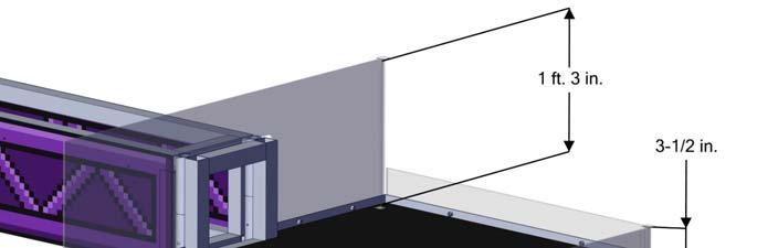
13 Blinking: indicates that either the Field Management System is preset for the MATCH or it s during a MATCH and the corresponding ROBOT has lost connectivity. Off: indicates that the MATCH has not started yet, but the ROBOT is linked and disabled. If the amber LED is on, the E-stop button has been pressed. One Timer (in the PORTAL adjacent to PLAYER STATION 1): displays the official time remaining in AUTO, TELEOP, and TIMEOUTS and marked with white tape along the bottom edge. Field Management System hardware and wiring: mostly located below the center PLAYER STATION shelf. EXCHANGE An EXCHANGE is a polycarbonate wall 6 ft. 5 ¾ in. (~197 cm) tall by 4 ft. (~122 cm) wide located between PLAYER STATION 1 and PLAYER STATION 2 and used by ROBOTS to deliver POWER CUBES to HUMAN PLAYERS. HUMAN PLAYERS can then either place POWER CUBES in the VAULT or feed them back to the ROBOT through the RETURN. Each EXCHANGE has a lower opening 1 ft. 4 ¼ in. (~41 cm) tall and is 1 ft. 9 in. (~53 cm) wide used to deliver POWER CUBES to the HUMAN PLAYER. A small ramp, 1 ¾ in. (~4 cm) tall by 6 ½ in. (~17 cm) deep, leads to a series of conveyor rollers. The conveyor rollers are spun by the HUMAN PLAYER to move the POWER CUBE through a polycarbonate tunnel that is 1 ft. 11 ¾ in. (~60 cm) deep. Each EXCHANGE also features a RETURN used to deliver POWER CUBES to ROBOTS. The RETURN opening is a 1ft. 2 in. (~36 cm) square, centered above the lower opening and is located 1 ft. 8 in. (~51 cm) above the carpet. Behind the RETURN opening is a 1 ft. 6 ½ in. (~47 cm) deep polycarbonate chute. The chute features a swinging wall designed to push the POWER CUBE onto the FIELD. Figure 3-18: EXCHANGE VAULT The VAULT is an aluminum and plastic structure used by HUMAN PLAYERS to turn POWER CUBES in to POWER UPS. There are three (3) columns within the VAULT. Each column is 1 ft. 1-1/2 in. (~34 cm) wide by 3 ft. 3-1/4 in. (~100 cm) tall with the bottom located 1 ft. 3-1/2 in. (~39 cm) above the carpet. Each of the three (3) columns in the VAULT correspond to a POWER UP. When standing in the V5 27 of 129
 POWER CUBES will not fit in a VAULT column, but if HUMAN PLAYERS place POWER CUBES logo side up they ll fit")
14 ALLIANCE STATION and facing the open columns of the VAULT the column to the left is the FORCE POWER UP, the center column is the LEVITATE POWER UP and the column on the right is the BOOST POWER UP. Figure 3-19: Blue ALLIANCE VAULT Caution, there may be orientations where all three (3) POWER CUBES will not fit in a VAULT column, but if HUMAN PLAYERS place POWER CUBES logo side up they ll fit with room to spare. V5 28 of 129
15 VAULT lighting Lights at the top of each VAULT column display the POWER CUBE count for that column. The lights have the following states: Table 3-2: VAULT Lighting Color Meaning No POWER CUBES in column One (1) POWER CUBE in column Two (2) POWER CUBES in column Three (3) POWER CUBES in column (pulsing) Blue POWER UP in queue Blue POWER UP played (pulsing) Red POWER UP in queue Red POWER UP played The lights illuminate one bulb per POWER CUBE and show one (1), two (2), three (3) or none (0) by lighting up from left to right. To play a POWER UP, the button corresponding to the column and associated POWER UP is pressed by the HUMAN PLAYER. Once played, all five (5) lights in the corresponding column are illuminated in the ALLIANCE color. If an ALLIANCE plays a POWER UP during the time when an opposing ALLIANCE s POWER UP is active, the POWER UP is queued, indicated by five (5) pulsing lights. See Section 4.3 POWER UPS for more details. V5 29 of 129

 polycarbonate chute.")
16 3.7 PORTAL HUMAN PLAYERS may deliver POWER CUBES to ROBOTS through either of the PORTAL walls. Each PORTAL wall features a 1 ft. 2 in. (~36 cm) square opening, centered across the width of the panel and located 1 ft. 8 in. (~51 cm) from the carpet. Behind the opening is a 1 ft. 6 ½ in. (~47 cm) polycarbonate chute. The chute featues a swinging wall that the HUMAN PLAYER uses to push the POWER CUBE onto the FIELD. Figure 3-20: PORTAL V5 30 of 129
 tall HDPE milk crate covered in a yellow nylon (600 Denier) cover. The FIRST logo covers the open face of the milk crate. Each POWER CUBE weighs approximately 3 ¼ lbs (~1.5 kg).")
17 3.8 POWER CUBE POWER CUBES are used to affect the position of the SCALE and SWITCH PLATES, and can be traded in for POWER UPS. A POWER CUBE is a 1 ft. 1 in. (~33 cm) wide by 1 ft. 1 in. (~33 cm) deep by 11 in. (~27 cm) tall HDPE milk crate covered in a yellow nylon (600 Denier) cover. The FIRST logo covers the open face of the milk crate. Each POWER CUBE weighs approximately 3 ¼ lbs (~1.5 kg). POWER CUBES may be purchased from AndyMark (am-3818 and am-3741), Innovation First ( and ), and Rev Robotics (REV and REV ). Please note that due to the use of recycled material in the manufacturing process, the batches of crates will vary slightly in color, but not such that it s perceptible with the cover in place. Figure 3-21: POWER CUBE 3.9 Vision Targets Vision targets are located on the SWITCH FENCE facing the ALLIANCE WALL using 2 in. (~5 cm) strips of 3M 8830 Scotchlite Reflective Material and are used to highlight the locations of the PLATES on the SWITCH. Each vision target consists of two vertical, 16 in. (~41 cm) tall strips of reflective material, with a 4 in. (~10 cm) gap between them. Elements of the SWITCH obscure the top and bottom of the target, resulting in approximately 15.3 in. (~39 cm) of viewable height when viewed straight on. The center of each target is located 51 7/8 in. (~132 cm) from the center of the SWITCH. V5 31 of 129
18 Figure 3-22: Vision Target locations 3.10 The FIELD Management System The FIELD Management System (FMS) is the electronics core responsible for controlling the FIRST Robotics Competition playing field. The FMS encompasses all field electronics, including the computers, REFEREE touchscreens, wireless access point, sensors, stack lights, E-Stops, etc. When a DRIVE TEAM connects the Ethernet cable from their assigned PLAYER STATION to their OPERATOR CONSOLE, the Driver Station software on the OPERATOR CONSOLE computer will begin to communicate with the Field Management System (FMS). Once connected to FMS, the only open ports available are described in Table 3-3. Table 3-3: Open FMS Ports Port Designation Bi-directional? UDP/TCP Camera data from the roborio to the Driver Station (DS) when the camera is connected Yes the roborio via USB TCP 1735 SmartDashboard Yes UDP 1130 Dashboard-to-ROBOT control data Yes UDP 1140 ROBOT-to-Dashboard status data Yes HTTP 80 Camera connected via switch on the ROBOT Yes HTTP 443 Camera connected via switch on the ROBOT Yes UDP/TCP 554 Real-Time Streaming Protocol for h.264 camera streaming Yes UDP/TCP Team Use Yes Teams may use these ports as they wish if they do not employ them as outlined above (e.g. TCP 1180 can be used to pass data back and forth between the ROBOT and the Driver Station software if the Team chooses not to use the camera on USB). Note that ROBOT code cannot be deployed while connected to the FMS. Additional information about the FMS may be found in the FMS Whitepaper. The FMS provides the ALLIANCE color assigned to each PLATE to the Driver Station software. Immediately following the assignment of PLATE color prior to the start of AUTO. Specific details on the format of the data can be found on the 2018 FRC Control System website. While FMS does provide the ALLIANCE PLATE color to each team s Driver Station, teams must write the necessary ROBOT code to make use of the information during a MATCH. V5 32 of 129
19 FMS alerts participants to milestones in the MATCH using audio cues. Please note that audio cues are intended to be a courtesy to participants and not intended as official MATCH markers. If there is a discrepancy between an audio cue and the FIELD timers, the FIELD timers are the authority. MATCH Start & PLATES randomized: Startup Sound AUTO Start: Cavalry Charge T=0 for AUTO: Buzzer Start of TELEOP: Three (3) Bells T-30 seconds in TELEOP: Train Whistle T=0 for TELEOP/MATCH end: Buzzer MATCH stopped: Foghorn POWER UP activated: Linear Popping" V5 33 of 129
20
2013, 2014 Hewlett-Packard Development Company, L.P.
 User Guide 2013, 2014 Hewlett-Packard Development Company, L.P. The only warranties for HP products and services are set forth in the express warranty statements accompanying such products and services.
Interview Management System Installation Guide
 Technical Support Interview Management System Installation Guide www.casecracker.com support@casecracker.com (720) 442-7072 Technologies 2017 (v.15) 1 Equipment Checklist Box 1 Box 2 Box 3 (Optional) CaseCracker
A Full Line of Robots for Injection Molding: YS and ST Series Sprue Pickers SB Series Servo Robots SC Series Heavy Duty Servo robots
 Machinery Center Inc. Presents A Full Line of Robots for Injection Molding: YS and ST Series Sprue Pickers SB Series Servo Robots SC Series Heavy Duty Servo robots APEX DYNAMICS, INC. A worldwide leading
BLINKIN LED DRIVER USER'S MANUAL. REV UM-0 Copyright 2018 REV Robotics, LLC 1
 fg BLINKIN LED DRIVER USER'S MANUAL REV-11-1105-UM-0 Copyright 2018 REV Robotics, LLC 1 TABLE OF CONTENTS 1 OVERVIEW... 3 1.1 CONNECTIONS... 3 1.2 KIT CONTENTS... 3 1.3 ELECTRICAL RATINGS... 3 1.4 SUPPORTED
Guidelines for Wiring, Electronic Timing and Scoring Systems Table of Contents
 Guidelines for Wiring, Electronic Timing and Scoring Systems Table of Contents 1. INTRODUCTION PAGE 2 2. VELORESULTS PAGE 2 3. 250 METER TRACK PAGE 2 4. STARTERS STAND PAGE 2-3 5. JUDGES STAND PAGE 3 6.
Room Recommendations for the Cisco TelePresence System 3210
 CHAPTER 2 Room Recommendations for the Cisco TelePresence System 3210 Revised: February 20, 2012, This chapter provides you with general room recommendations for the Cisco TelePresence System 3210 (CTS
ICS Digital Menu. Installation Guide Version 1.1
 ICS Digital Menu Installation Guide Version 1.1 Installation Overview This document was written to assist technicians and electricians in installing the ICS Digital Menu. A thorough understanding of electrical
Series 2500 Vibration Isolation Table
 Series 2500 Vibration Isolation Table October 2008 1741 W. University Drive, Ste. 146 1741 W. University Drive, Ste. 146 Now, even better! The Series 2500 Vibration Isolation Table has been very well received.
Azatrax Model Railroad Track Signal Control - Single Track
 Installation Guide Azatrax Model Railroad Track Signal Control - Single Track TS2 What it is: The TS2 operates one or two trackside block signals (one in each direction) on one track to simulate the block
Kazo Vision. 1. System Chart
 Timing & Scoring System for Track Track Timing System is an automatic timing system, which combines the software and hardware and uses high-speed color CCD digital camera. It can realize the automation
Formulate Designer Series 20 Backwall - Kit 07
 Formulate Designer Series 20 Backwall - Kit 07 FMLT-DS-20-07 Formulate TM Designer Series 20ft displays have unique stylistic features and shapes, are portable and easy to assemble. The aluminum tube frame
Interview Management System Installation Guide. (303) x500
 x500") Technical Support Interview Management System Installation Guide www.casecracker.com support@casecracker.com (303) 665-3962 x500 Copyright Cardinal Peak Technologies 2015 (v.10) 1 Equipment Checklist Box
Technical Support Interview Management System Installation Guide www.casecracker.com support@casecracker.com (303) 665-3962 x500 Copyright Cardinal Peak Technologies 2015 (v.10) 1 Equipment Checklist Box
CONTENT Product Introduction... 2 Packing Configuration...3 Hardware Orientation... 4 Front Panel... 4 Back Panel... 6 Using Your Product... 7 Content
 VENUS X1PRO Quick Start 4K input support in DP, HDMI and DVI Input standard 2K formats Scale and switch seamlessly between 2K and 4K inputs Output to any format 2K or 4K EDID management on board HDCP 2.0
Color mixing or White-light LED (Light Emitting Diode) ERS-style product
 ERS-style product") WHT Color mixing or White-light LED (Light Emitting Diode) ERS-style product GENERAL PHYSICAL A. The product shall be an Ovation E-910FC as manufactured by Chauvet & Sons, LLC or approved equal. 1. The
WHT Color mixing or White-light LED (Light Emitting Diode) ERS-style product GENERAL PHYSICAL A. The product shall be an Ovation E-910FC as manufactured by Chauvet & Sons, LLC or approved equal. 1. The
Model 6527 & 6827 Single Line Scoreboard Owner s Manual
 Model 6527 & 6827 Single Line Scoreboard Owner s Manual Portatree Eliminator 2000 Compatible Rev C RaceAmerica Corp. 280 Martin Ave. Unit#1 Santa Clara, CA 95050 (408) 988-6188 www.raceamerica.com info@raceamerica.com
Check what you have received against the component checklist and hardware above.
 SA46S SA46W SA46B SA46PB Component Checklist Installation Instructions SYSTEMA Systema Monitor Arm 460mm HARDWARE Display Mounting Spacers (x4) Display Mounting Screws Arm Assembly VESA monitor head M4
SAPLING WIRED SYSTEM
 SAPLING WIRED SYSTEM Sapling 2-Wire System DESCRIPTION The Sapling 2-Wire System is one of the most innovative and advanced wired systems in the synchronized time industry. It starts with the SMA Series
F7000NV ROBOT VISION OPERATING MANUAL
 Rev. C Feb 2012 F7000NV ROBOT VISION OPERATING MANUAL Rev. C Feb 2012 This page has intentionally been left blank. Contents Contents Chapter 1. Getting Started... 5 1. Preface... 5 2. Manuals... 5 3. Setting
PSC300 Operation Manual
 PSC300 Operation Manual Version 9.10 General information Prior to any attempt to operate this Columbia PSC 300, operator should read and understand the complete operation of the cubing system. It is very
READ ME FIRST. Touchstone TV Lift
 Whisper Lift II PRO 2 READ ME FIRST 1. After completing the unpacking and uncrating of the cabinet, you will find the Owner s Manual, TV, installation hardware, and the wireless remote all together and
Setup Guide. Read me BefoRe unpacking!
 Setup Guide Read me BefoRe unpacking! Package Contents In The Replicator package The Replicator SD card (in The Replicator SD card slot) In the Accessory Box found within The Replicator frame Single or
CONTRACTORS SPECIFICATION
 VICON PRODUCT SPECIFICATION NOTES SPEC NO. REV. SEC. SUPERSEDES PRODUCT SPECIFICATION 735-594 735 1299 10 MODEL: V1902VCT PRODUCT CODES: REFER TO TABLE 1 DESCRIPTION: VICOAX TRANSMITTER FOR A COAXIAL CONTROL
QuickSpecs. HP V19b 18.5-inch Monitor. Overview. 1. Menu 3. Plus ( + ) 5. Power 2. Minus ( - ) 4. OK. 1. Power connector 3. Security lock slot 2.
 5. Power 2. Minus ( - ) 4. OK. 1. Power connector 3. Security lock slot 2.") Overview 1. Menu 3. Plus ( + ) 5. Power 2. Minus ( - ) 4. OK 1. Power connector 3. Security lock slot 2. VGA Brazil Version 1 April 20, 2018 Page 1 Model: 2XM32AA Panel Type 18.5-inch TN Viewable Image
Overview 1. Menu 3. Plus ( + ) 5. Power 2. Minus ( - ) 4. OK 1. Power connector 3. Security lock slot 2. VGA Brazil Version 1 April 20, 2018 Page 1 Model: 2XM32AA Panel Type 18.5-inch TN Viewable Image
Power Injector 1520 Series
 Power Injector 1520 Series Technical Specifications Input voltage 100 to 240 VAC Output voltage 56.0 VDC Voltage range tolerance 54 VDC to 57 VDC Maximum current 1.43 A No load current 15 ma 56VDC@0.71A
2000i. Projector Replacement Guide. for Projector Replacement Kits. NEC MT1060R ( ) and NEC MT860R ( ) Interactive Whiteboard
 and NEC MT860R ( ) Interactive Whiteboard") 2000i Interactive Whiteboard Projector Replacement Guide for Projector Replacement Kits NEC MT1060R (03-00043) and NEC MT860R (03-00041) 99-00496-00 Rev A0 FCC Warning This equipment has been tested and
2000i Interactive Whiteboard Projector Replacement Guide for Projector Replacement Kits NEC MT1060R (03-00043) and NEC MT860R (03-00041) 99-00496-00 Rev A0 FCC Warning This equipment has been tested and
RACKS, ENCLOSURES AND CABLE MANAGEMENT
 and RS3 RACK SYSTEM (pages 6.2 6.3) RS RACK SYSTEM (pages 6.4 6.5) EXTENDED DEPTH RS RACK SYSTEM (page 6.5) Vertical Side Rail Capacity Cable Manager Covers Accessories 117mm x 152mm (4.6 in. x 6.0 in.)
April 2018 TALL FOOD & PHARMA PRODUCT INSPECTION
 April 2018 TALL FOOD & PHARMA PRODUCT INSPECTION World-Class Detection Anritsu's Side View applies the XR75's renowned detection to rigid and tall products. Anritsu HD imaging technology is now available
Dell 1510X Projector. User s Guide
 Dell 1510X Projector User s Guide Notes, Notices, and Cautions NOTE: A NOTE indicates important information that helps you make better use of your projector. NOTICE: A NOTICE indicates either potential
ENERGY STAR Program Requirements Product Specification for Televisions. Eligibility Criteria Version 5.3
 ENERGY STAR Program Requirements Product Specification for Televisions Eligibility Criteria Version 5.3 Following is the Version 5.3 ENERGY STAR Product Specification for Televisions. A product shall meet
Part names (continued) Remote control
 Remote control") Introduction Part names (continued) Remote control (1) STANDBY ( 25) (1) (2) ON ( 25) (3) (3) ID - 1 / 2 / 3 / 4 s ( 18) (4) (4) COMPUTER 1 ( 27) (7) (5) COMPUTER 2 * (8) (6) COMPUTER 3 * (10) (13) (7)
Introduction Part names (continued) Remote control (1) STANDBY ( 25) (1) (2) ON ( 25) (3) (3) ID - 1 / 2 / 3 / 4 s ( 18) (4) (4) COMPUTER 1 ( 27) (7) (5) COMPUTER 2 * (8) (6) COMPUTER 3 * (10) (13) (7)
Instruction Manual for the & Electronic Bingo Blower
 Instruction Manual for the 17212 & 17214 Electronic Bingo Blower The directions in this manual when referring to the 17212 are referring to software version 2.83 (you can find what version your blower
Channel Cable Tray - Accessories
 Splice Plate The Splice Plate has the standard 4-hole pattern for all cable channel. Provided with straight sections and fittings. 9(*)-1043 3 (76) 9(*)-1044 4 (101) 9(*)-1044-6 6 (152) Horizontal Adjustable
Operating Manual. Automated Gear. Apollo Design Technology, Inc Fourier Drive Fort Wayne, IN USA
 Operating Manual Automated Gear Apollo Design Technology, Inc. 4130 Fourier Drive Fort Wayne, IN 46818 USA PH: +01(260)497-9191 FX: +01(260)497-9192 www.apollodesign.net 11-25-09 5-6 POWERING UP THE RIGHT
HP EliteDisplay LED Backlit Monitors. User Guide
 HP EliteDisplay LED Backlit Monitors User Guide 2013 Hewlett-Packard Development Company, L.P. Microsoft and Windows are U.S. registered trademarks of Microsoft Corporation. The only warranties for HP
OWNER S MANUAL MOTORIZED 7 WIDE TFT LCD COLOR MONITOR CNT-701
 OWNER S MANUAL PW MOTORIZED 7 WIDE TFT LCD COLOR MONITOR CNT-701 ANY CHANGES OR MODIFICATIONS IN CONSTRUCTION OF THIS UNIT DEVICE WHICH IS NOT APPROVED BY THE PARTY RESPONSIBLE FOR COMPLIACE COULD VOID
SBL /SBLG Series Wireless Clock
 Installation Manual V8.3 SBL /SBLG Series Wireless Clock Current as of August 2018 The Sapling Company, Inc. SBL and SBLG Series Wireless Clocks Table of Contents Table of Contents 2 Important Safety Instructions
Room Recommendations for the Cisco TelePresence System 3010
 CHAPTER 2 Room Recommendations for the Cisco TelePresence System 3010 Revised: July 13, 2012, This chapter provides you with general room recommendations for the Cisco TelePresence System 3010 (CTS 3010)
Dell Wyse 5030 PCoIP Zero Client
 Dell Wyse 5030 PCoIP Zero Client User Guide Regulatory Model: PxN Regulatory Type: PxN001 Notes, cautions, and warnings NOTE: A NOTE indicates important information that helps you make better use of your
Stud Welding Equipment
 Stud Welding Equipment 10/16 N550c Arc Charger Breakthrough Charger design provides powerful 550A Arc Welder from 120V wall outlet! The N550c Arc Charger is the first of a revolutionary new class of stud
Reference Manual. Notes 9/16 Series H
 Reference Manual Notes 9/16 Series 173.01H Copyright notice The information in this document is subject to change without prior notice and does not represent a commitment on the part of Q-MATIC AB. All
VSP 198CVS Quick Start
 VIEWSIZE THE WORLD VSP 198CVS Quick Start Max 2048 1152@60Hz/2560 1152 50Hz input/output resolution User customize output resolution 3G/HD/SD-SDI input Multiple cascade mapping for super resolution DVI
Dell D3218HN. User s Guide. Regulatory model: D3218HNo
 Dell D3218HN User s Guide Regulatory model: D3218HNo Notes, cautions, and warnings NOTE: A NOTE indicates important information that helps you make better use of your computer. CAUTION: A CAUTION indicates
BUREAU OF ENERGY EFFICIENCY
 Date: 26 th May, 2016 Schedule No.: 11 Color Televisions 1. Scope This schedule specifies the energy labeling requirements for color televisions with native resolution upto 1920 X 1080 pixels, of CRT,
Gazer VI700A-SYNC2 and VI700W- SYNC2 INSTALLATION MANUAL
 Gazer VI700A-SYNC2 and VI700W- SYNC2 INSTALLATION MANUAL Contents List of compatible cars... 3 Package contents... 4 Special information... 6 Car interior disassembly and connection guide for Ford Focus...
Selecon LED Fixtures. PL3 LED Luminaire. Features SPECIFICATION SUBMITTAL
 A revolutionary breakthrough in stage and studio lighting, the PL3 LED Luminaire delivers full control of the beam color composition irrespective of intensity. Drawing on technology and specific insight,
USER MANUAL. GOLDMUND LOGOS 1N-2N SPEAKER SYSTEM Active Speaker
 USER MANUAL GOLDMUND LOGOS 1N-2N SPEAKER SYSTEM Active Speaker Thank you for purchasing the Goldmund LOGOS 1N-2N SPEAKER SYSTEM The Goldmund Logos line fully incorporates the technological expertise developed
USER MANUAL. Vidifox Document Camera DV 480
 Vidifox Document Camera DV 480 USER MANUAL Please read this User Manual thoroughly before you use the document camera. Keep the CD-ROM in a convenient place so you can use it quickly if you need to. Please
ControlTrac PRODUCT GUIDE tbcconsoles.com
 ControlTrac PRODUCT GUIDE tbcconsoles.com TABLE OF CONTENTS CTL SERIES OVERVIEW... PAGE 3 FEATURES... PAGE 4 PRE-CONFIGURED CONSOLES STRAIGHT... PAGE 5 PRE-CONFIGURED CONSOLES ANGULAR... PAGE 6 E SERIES
Sound to Sight Showtime
 Sound to Sight Showtime Instruction Manual Sound to Sight Showtime 22870, March 2018 Copyright ROMPA Ltd Contents 3 At a Glance Panel Overview Colour Description Contents Technical Specification What s
QUICK PATCH Coaxial Patch Panels
 QUICK PATCH Coaxial Patch Panels Features Unique quick connect design Auto locking Reduced weight Various standard port arrangements Positive pre-removal interlocks Replaceable contacts Standard Configurations
HP Engage One 10.1 Display (Black) HP Engage One 10.1 Display (White)
 HP Engage One 10.1 Display (White)") Overview Models (Black) (White) 1XD80AA 3FH66AA Introduction Share dynamic videos and content with customers on a display that gets attention in any room with the HP Engage One 10.1 n-touch Display for
Overview Models (Black) (White) 1XD80AA 3FH66AA Introduction Share dynamic videos and content with customers on a display that gets attention in any room with the HP Engage One 10.1 n-touch Display for
Gazer VI700A-SYNC/IN and VI700W- SYNC/IN INSTALLATION MANUAL
 Gazer VI700A-SYNC/IN and VI700W- SYNC/IN INSTALLATION MANUAL Contents List of compatible cars... 3 Package contents... 4 Special information... 6 Car interior disassembly and connection guide for Ford
Saddle-stitching System StitchLiner5500
 Saddle-stitching System StitchLiner5500 Combining the efficiency and ease of operation of flat sheet collating with the productivity, versatility and quality of a saddle-stitching system. The StitchLiner5500
SPECIFICATION NO NOTE
 NOTE The Model 207-1 is a special version of the standard M-207 Power Supply. It has been altered for a special applications requiring low current operation at high arc voltages in ambient and pressurized
NewScope-7A Operating Manual
 2016 SIMMCONN Labs, LLC All rights reserved NewScope-7A Operating Manual Preliminary May 13, 2017 NewScope-7A Operating Manual 1 Introduction... 3 1.1 Kit compatibility... 3 2 Initial Inspection... 3 3
515 PIPEMASTER. Features. Options PROGRAMMABLE POWER SOURCE FOR ORBITAL WELD HEADS
 PIPEMASTER 515 515 PIPEMASTER PROGRAMMABLE POWER SOURCE FOR ORBITAL WELD HEADS The latest generation of Pipemaster power sources is the result of a new direction in power source design. The Pipemaster
THE AMBER COMPUTER VDU PROJECT.
 THE AMBER COMPUTER VDU PROJECT. H. Holden. April. 2019. BACKGROUND: Of the vintage small cathode ray tube VDU s or video monitors, the one that has impressed me the most, is the one manufactured by Zenith
M2 Antenna Systems, Inc. Model No: 23CM35
 M2 Antenna Systems, Inc. Model No: 23CM35 SPECIFICATIONS: Model... 23CM35 Frequency Range... 1250 To 1300 MHz *Gain... 20.94 dbi Front to back... 25 db Typical Beamwidth... E=17 H=18 Feed type... Folded
Support Frame STB Technical Instruction Manual
 Support Frame STB Technical Instruction Manual Fig. 2.1: Support frame STB 450 Fig. 2.2: Support frame STB 300 Fig. 2.3: Brace bracket SK 150 Product Characteristics The support frames are mainly used
MAGNETIC CARD READER DESIGN KIT TECHNICAL SPECIFICATION
 MAGNETIC CARD READER DESIGN KIT TECHNICAL SPECIFICATION Part Number: D99821002 Rev 212 MAY 2017 REGISTERED TO ISO 9001:2008 1710 Apollo Court Seal Beach, CA 90740 Phone: (562) 546-6400 FAX: (562) 546-6301
K Service Source. Macintosh Color Display
 K Service Source Macintosh Color Display K Service Source Specifications Macintosh Color Display Specifications Characteristics - 1 Characteristics Picture Tube 14-in. diagonal (11.5-in. viewable image)
Caution. Hanging the Screen:
 Installation Instructions for Laminar and Laminar XL Projection Screens Caution 1. Read Instructions through completely before proceeding; keep them for future reference. Follow these instructions carefully.
Modular Lube Lubrication Systems System Controls
 Model 84501 Program Timer Solid State Designed to control the lubrication cycle frequency of air-operated single-stroke pumps. Timer turns pump on/off at programmed intervals via a 3-way or 4-way air solenoid
QuickSpecs. HP V214a 20.7-inch Monitor. HP V214a 20.7-inch Monitor. Overview. 1. Menu 3. Plus ( + ) 5. Power 2. Minus ( - ) 4. OK
 5. Power 2. Minus ( - ) 4. OK") Overview 1. Menu 3. Plus ( + ) 5. Power 2. Minus ( - ) 4. OK 1. Security lock slot 4. VGA 2. Power connector 5. Audio in 3. HDMI 1.4 c05547340 DA 15984 Worldwide Version 2 April 5, 2018 Page 1 Models:
Overview 1. Menu 3. Plus ( + ) 5. Power 2. Minus ( - ) 4. OK 1. Security lock slot 4. VGA 2. Power connector 5. Audio in 3. HDMI 1.4 c05547340 DA 15984 Worldwide Version 2 April 5, 2018 Page 1 Models:
>Inductive and. REFERENCE guide. Capacitive Sensors
 >Inductive and REFEREE guide Capacitive Sensors DATALOGIC: SOLUTIONS FOR INDUSTRIAL AUTOMATION Datalogic Industrial Automation is an industry-leader in products and solutions for material handling, traceability,
ENGR 1000, Introduction to Engineering Design
 Unit 2: Mechatronics ENGR 1000, Introduction to Engineering Design Lesson 2.3: Controlling Independent Systems Hardware: 12 VDC power supply Several lengths of wire NI-USB 6008 Device with USB cable Digital
Specifications Quantum Elite Series
 Specifications Quantum Elite Series Video input composite and S-video QEC I12VID Number/signal type... 12 S-video, composite video Connectors... 2 female 26-pin HD (included adapter allows input on 24
15-06 Morlot Avenue, Fair Lawn, NJ USA Tel: (201) Fax: (201)
 Fax: (201)") 15-06 Morlot Avenue, Fair Lawn, NJ 07410 USA Tel: (201) 796-2690 Fax: (201) 796-8818 info@articulight.com articulight@aol.com www.articulight.com LED SERIES CHROMA TOWER 500 Imagine being able to change
15-06 Morlot Avenue, Fair Lawn, NJ 07410 USA Tel: (201) 796-2690 Fax: (201) 796-8818 info@articulight.com articulight@aol.com www.articulight.com LED SERIES CHROMA TOWER 500 Imagine being able to change
SPECIFICATION NO Model 207 Automatic GTAW Welding System
 1.0 Introduction The Model 207 is a completely self-contained Gas Tungsten Arc Welding (GTAW) System requiring only input power, inert gas and AMI Welding Head (or manual torch) for operation. Its small
QuickSpecs. Overview. Key features: HP V193f 18.5-inch Monitor. Technical Specifications
 1. Menu button 4. OK/Auto 2. Minus 5. Power button 3. Plus Overview Get quality presentation features at a price point that doesn t break the bank with the HP V193f 18.5-inch LED Backlit Monitor. Key features:
NEW! Wide Area Lighting - Rough Service Fluorescent. MULTIVOLTAGE Automatically Operates at 120 to 277 VAC 50 or 60 Hz *1142 only
 Wide Area Lighting - Rough Service Fluorescent 1100 and 1200 Series Wide Area Lighting These portable overhead lights have been engineered to meet the need for safe, temporary, economical lighting for
SPECIAL SPECIFICATION 2344 TMC Support Equipment
 2004 Specifications CSJ 0912-00-488 SPECIAL SPECIFICATION 2344 TMC Support Equipment 1. Description. Furnish Traffic Management Center (TMC) support equipment in the City of Missouri City TMC location
Main Stage Technical Specs - Hall #2
 Main Stage Technical Specs - Hall #2 Proscenium: - Height:...20' (06.10m) - Width:...31' 10"(09.70m) Apron: - Depth:...4' (01.22m) - Width:...45' 6" (13.87m) - Height:...3' 7" (01.09m) Stage: - Maximum
MODULA SERIES QUICK SPECIFICATIONS
 TM MODULA SERIES QUICK SPECIFICATIONS www.thureon.com September01 www.thureon.com Armarac Modula M Series Quick Specs Where space is at a premium, or where security and environmental control are essential.
Mobile Projector Kit KIT CONTAINS:
 Mobile Projector Kit Enhance your presentations by showing images with this ultra-portable, small, and lightweight projector. It provides bright, crisp, high-resolution LED projection, with a built-in
imac Intel 20" EMC 2133 and 2210 LCD Backlights (CCFL) Replacement
 Replacement") imac Intel 20" EMC 2133 and 2210 LCD Backlights (CCFL) Replacement The CCFL back lights are replaceable. I have pulled mine apart and documented my method. '''NOTE''' This is not for the feint hearted!
imac Intel 20" EMC 2133 and 2210 LCD Backlights (CCFL) Replacement The CCFL back lights are replaceable. I have pulled mine apart and documented my method. '''NOTE''' This is not for the feint hearted!
OEM Basics. Introduction to LED types, Installation methods and computer management systems.
 OEM Basics Introduction to LED types, Installation methods and computer management systems. v1.0 ONE WORLD LED 2016 The intent of the OEM Basics is to give the reader an introduction to LED technology.
L1752SE L1952SE. User s Guide
 User s Guide L1752SE L1952SE Make sure to read the Important Precautions before using the product. Keep the User's Guide(CD) in an accessible place for furture reference. See the label attached on the
Trimble TMX-2050 Display Quick Reference Card
 Trimble TMX-2050 Display Quick Reference Card The Trimble TMX-2050 display is a touchscreen platform for precision agriculture. Home screen Left side of screen Right side of screen Tap the buttons on the
QuickSpecs. HP VH27 27-inch Monitor. Overview. 1. Menu 3. Plus ( + ) 5. Power 2. Minus ( - ) 4. Exit
 5. Power 2. Minus ( - ) 4. Exit") Overview 1. Menu 3. Plus ( + ) 5. Power 2. Minus ( - ) 4. Exit 6. Security lock slot 8. DisplayPort TM 7. Power connector 9. HDMI 10. VGA NA Version 2 April 5, 2017 Page 1 Models: 2KZ36A - 3PL18A Panel
Overview 1. Menu 3. Plus ( + ) 5. Power 2. Minus ( - ) 4. Exit 6. Security lock slot 8. DisplayPort TM 7. Power connector 9. HDMI 10. VGA NA Version 2 April 5, 2017 Page 1 Models: 2KZ36A - 3PL18A Panel
Altman Lighting Spectra Cyc 50 Specification
 1.01 CYCLORAMA LIGHTING A. General 1. The fixture shall be a compact, lightweight color-mixing LED asymmetrical wash fixture with 8 or 16 bit DMX control of intensity and color. The fixture shall be the
General Specifications
 General Specifications WG41F11C Compact O Frame GS 14M04B10-20E-Z1 [Style: S1] Overview The WG41F11C Compact O frame is a space-saving frame designed for coating lines of battery electrode sheets. This
TECHNICAL FOCUS: PRODUCT IN DEPTH
 Copyright Lighting&Sound America October 2017 http://www.lightingandsoundamerica.com/lsa.html Chauvet Professional Ovation B-1965FC By: Mike Wood Figure 1: Fixture as tested. You may have noticed that
Installation Guide OvalSox TM Cable
 Installation Guide OvalSox TM Cable Thank you for selecting a DuctSox System. This guide will be helpful for the installation of an OvalSox Cable System. Sections of fabric will be labeled, assembled,
BigTime. Deployment Entertainment System SETUP AND OPERATING MANUAL. Powerful, Compact Road Case Does It All! KARAOKE GAME SHOWS GAMING MOVIES
 BigTime INDOOR AND OUTDOOR MWR REC Deployment Entertainment System Powerful, Compact Road Case Does It All! When it comes to MWR entertainment... Bigger Is Better! Celebrity s new outdoor deployment bundle
S0 Radio Broadcasting Mixer. June catalogue. Manufacturers of audio & video products for radio & TV broadcasters
 S0 Radio Broadcasting Mixer June 2012 catalogue Manufacturers of audio & video products for radio & TV broadcasters S0 Radio Broadcasting Mixer A simple radio mixer for novice and professional users The
Unauthorized changes or modification to this system can void the user s authority to operate this equipment.
 Users Manual PLUS Congratulations on your purchase of Merlin Plus from Enhanced Vision. Merlin Plus is designed to enhance the lifestyle of the visually impaired. This is Enhanced Vision s most advanced
LeRIBSS MTC MANUAL. Issue #1. March, MTC Control Unit Definitions, Information and Specifications. MTC Control Unit Electronic Schematics
 LeRIBSS MTC MANUAL Issue #1 March, 2008 Contents: MTC Control Unit MTC Control Unit Definitions, Information and Specifications Programming the MTC Control Unit Program Parameters Initial Setup Measuring
GY-HM200SP USERS GUIDE
 SCORING OVERLAYS GY-HM200SP USERS GUIDE Network Connections, Overlays and Scorebot Live Data Feeds 1 TABLE OF CONTENTS Introduction 3 Step 1: Selecting an Overlay 4 Step 2: Establishing a Connection P2P
ivw-fd122 Video Wall Controller MODEL: ivw-fd122 Video Wall Controller Supports 2 x 2 Video Wall Array User Manual Page i Rev. 1.
 MODEL: ivw-fd122 Video Wall Controller Supports 2 x 2 Video Wall Array User Manual Rev. 1.01 Page i Copyright COPYRIGHT NOTICE The information in this document is subject to change without prior notice
PRESET TEN ARCHITECTURAL TWO OWNERS MANUAL
 PRESET TEN ARCHITECTURAL TWO OWNERS MANUAL model PRE10-A2 Doug Fleenor Design 396 Corbett Canyon Road Arroyo Grande, CA 93420 (805) 481-9599 Software Version 1.0 Manual Revision 12/2/2008 Serial # 08B001
GENUINE PARTS SATELLITE RADIO INSTALLATION INSTRUCTIONS. 1. DESCRIPTION: Satellite Radio System 2. APPLICATION: Frontier (2006~)
") GENUINE PARTS SATELLITE RADIO INSTALLATION INSTRUCTIONS 1. DESCRIPTION: Satellite Radio System 2. APPLICATION: Frontier (2006~) Xterra (2006~) 3. PART NUMBERS: XM Tuner Kit 999U9-AS003 SIRIUS Tuner Kit
GENUINE PARTS SATELLITE RADIO INSTALLATION INSTRUCTIONS 1. DESCRIPTION: Satellite Radio System 2. APPLICATION: Frontier (2006~) Xterra (2006~) 3. PART NUMBERS: XM Tuner Kit 999U9-AS003 SIRIUS Tuner Kit
QuickSpecs. Models RB146AA#ABA Standard Configuration RB146AT#ABA Promotional Part Number (SmartBuy) HP L5006tm 15-inch LCD Touchscreen Monitor
 HP L5006tm 15-inch LCD Touchscreen Monitor") Overview 1. 2. 3. 4. 5. Power: Turns the unit on and off. Select: Selects the adjustment items from the on-screen display (OSD) menus. Arrow down: Enter brightness adjustment, decrease value of the adjustment
Overview 1. 2. 3. 4. 5. Power: Turns the unit on and off. Select: Selects the adjustment items from the on-screen display (OSD) menus. Arrow down: Enter brightness adjustment, decrease value of the adjustment
Team Members: Erik Stegman Kevin Hoffman
 EEL 4924 Electrical Engineering Design (Senior Design) Preliminary Design Report 24 January 2011 Project Name: Future of Football Team Name: Future of Football Team Members: Erik Stegman Kevin Hoffman
SNG-2150C User s Guide
 SNG-2150C User s Guide Avcom of Virginia SNG-2150C User s Guide 7730 Whitepine Road Revision 001 Richmond, VA 23237 USA GENERAL SAFETY If one or more components of your earth station are connected to 120
MODULAR I/O DIGITAL AUDIO CONSOLE. Flexible. Affordable. Built To Last.
 MODULAR I/O DIGITAL AUDIO CONSOLE Flexible. Affordable. Built To Last. 2 Audioarts X-12 Digital MODULAR I/O DIGITAL AUDIO CONSOLE There was a time when handling digital audio was an option. Not anymore.
RMS 8424S Quick Start
 VIEWSIZE THE WORLD RMS 8424S Quick Start Standard 4 unit rack mount size 8 inch LCD 2 1024 3 (RGB) 600 16:9 / 4:3 adjustable SDI/HDMI embedded audio output via 3.5mm earphone socket Support SDI/DVI audio
Airborne series CONTENTS. General important information This short section must be read for proper operation
 Airborne series By Rafael Lozano-Hemmer CONTENTS General important information This short section must be read for proper operation Description Operation Cleaning Placement Instructions Wiring diagrams
QuickSpecs. HP 2211x 21.5-inch LED Backlit LCD Monitor Overview. 1. Menu
 Overview 1. Menu 2. Quick View Minus "-" 3. Source Plus "+" Opens, selects, or exits the OSD menu. NOTE: Pressing the Menu button for 10 seconds will disable operation of the remaining OSD buttons. Pressing
L194WS L204WS. User s Guide
 User s Guide L194WS L204WS Make sure to read the Important Precautions before using the product. Keep the User's Guide(CD) in an accessible place for furture reference. See the label attached on the product