Strand Lighting Locations
|
|
|
- Noah Marshall
- 6 years ago
- Views:
Transcription

1
2 Strand Lighting Locations Philips Strand Lighting - Dallas Petal Street Dallas, TX Tel: -- Fax: -- Philips Strand Lighting - New York th Ave, th Floor New York, NY Tel: -- Fax: -- Philips Strand Lighting - Auckland - Kawana Street Northcote, Auckland New Zealand Tel: + Fax: + Philips Strand Lighting - Europe Marssteden Enschede TD The Netherlands Tel: + Fax: + Philips Strand Lighting - Asia Limited Room -, /F Delta House On Yiu Street Shatin, N.T. Hong Kong Tel: + Fax: + Website: The material in this manual is for information purposes only and is subject to change without notice. Philips Strand Lighting assumes no responsibility for any errors or omissions which may appear in this manual. For comments and suggestions regarding corrections and/or updates to this manual, please visit the Philips Strand Lighting web site at or contact your nearest Philips Strand Lighting office. El contenido de este manual es solamente para información y está sujeto a cambios sin previo aviso. Philips Strand Lighting no asume responsabilidad por errores o omisiones que puedan aparecer. Cualquier comentario, sugerencia o corrección con respecto a este manual, favor de dirijirlo a la oficina de Philips Strand Lighting más cercana. Der Inhalt dieses Handbuches ist nur für Informationszwecke gedacht, Aenderungen sind vorbehalten. Philips Strand Lighting uebernimmt keine Verantwortung für Fehler oder Irrtuemer, die in diesem Handbuch auftreten. Für Bemerkungen und Verbesserungsvorschlaege oder Vorschlaege in Bezug auf Korrekturen und/oder Aktualisierungen in diesem Handbuch, moechten wir Sie bitten, Kontakt mit der naechsten Philips Strand Lighting Niederlassung aufzunehmen. Le matériel décrit dans ce manuel est pour information seulement et est sujet à changements sans préavis. La compagnie Philips Strand Lighting n'assume aucune responsibilité sur toute erreur ou ommission inscrite dans ce manuel. Pour tous commentaires ou suggestions concernant des corrections et/ou les mises à jour de ce manuel, veuillez s'il vous plait contacter le bureau de Philips Strand Lighting le plus proche. Note: Information contained in this document may not be duplicated in full or in part by any person without prior written approval of Philips Strand Lighting. Its sole purpose is to provide the user with conceptual information on the equipment mentioned. The use of this document for all other purposes is specifically prohibited. Document Number: STR- Version as of: November Plus Series Console Operations Manual Philips Group. All rights reserved.
3 Plus Series Console IMPORTANT INFORMATION Warnings and Notices When using electrical equipment, basic safety precautions should always be followed including the following: a. READ AND FOLLOW ALL SAFETY INSTRUCTIONS. b. Do not use outdoors. c. Do not use near gas or electric heaters. d. The use of accessory equipment not recommended by the manufacturer may cause an unsafe condition. e. Do not use this equipment for other than intended use. f. Refer service to qualified personnel. SAVE THESE INSTRUCTIONS. WARNING: You must have access to a main circuit breaker or other power disconnect device before installing any wiring. Be sure that power is disconnected by removing fuses or turning the main circuit breaker off before installation. Installing the device with power on may expose you to dangerous voltages and damage the device. A qualified electrician must perform this installation. WARNING: Do not open the console. There are no user serviceable parts inside. This equipment is designed to operate from the mains electrical supply and contains voltages, which, if touched, may cause death or injury. It should only be operated in accordance with the instructions provided and for the purpose of a lighting control system. WARNING: Avoid spilling liquid on the equipment If this should happen, switch the equipment off immediately at the mains. To reduce the risk of fire or electric shock, do not expose the equipment to rain or moisture. For indoor use only. WARNING: Refer to National Electrical Code and local codes for proper use specifications. WARNING: This equipment is intended for use in accordance with the National Electric Code and local regulations. It is also intended for installation in indoor applications only. Before any electrical work is performed, disconnect power at the circuit breaker or remove the fuse to avoid shock or damage to the control. It is recommended that a qualified electrician perform this installation. Additional Resources for DMX For more information on installing DMX control systems, the following publication is available for purchase from the United States Institute for Theatre Technology (USITT), "Recommended Practice for DMX: A Guide for Users and Installers, nd edition" (ISBN: ). USITT Contact Information: USITT Ridings Road Syracuse, NY - USA --USITT Philips Strand Lighting Limited Two-Year Warranty Philips Strand Lighting offers a two-year limited warranty of its products against defects in materials or workmanship from the date of delivery. A copy of Philips Strand Lighting two-year limited warranty containing specific terms and conditions can be obtained from the Philips Strand Lighting web site at or by contacting your local Philips Strand Lighting office.
4 Operations Manual TABLE OF CONTENTS Strand Lighting Locations... Inside Front Cover IMPORTANT INFORMATION Warnings and Notices... Additional Resources for DMX... Philips Strand Lighting Limited Two-Year Warranty... TABLE OF CONTENTS PREFACE About this Guide... Product Description... Compliance Information... Included Items... INTRODUCTION Plus Series Console Layout... Glossary of Terms... Getting Started... Site Requirements... Connecting Power... Connecting DMX... Rack Mounting... Product Care... Customer Service and Support... CONSOLE OPERATION Two Scene Operation... Manual Crossfades... Timed Crossfades... Single Scene Operation... Hold... Effect - Single Scene Mode... Effect - Two Scene Mode... Memory Operation... Record Mode... Playback Mode... Go Button Playback... Timed Playback... Preset Playback of Memories.... Timed Playback... Deleting Memories... Single Memory Deletion... All Memory Deletion... Preview Recorded Memories... TECHNICAL SPECIFICATIONS Electrical... Mechanical... TABLE OF CONTENTS

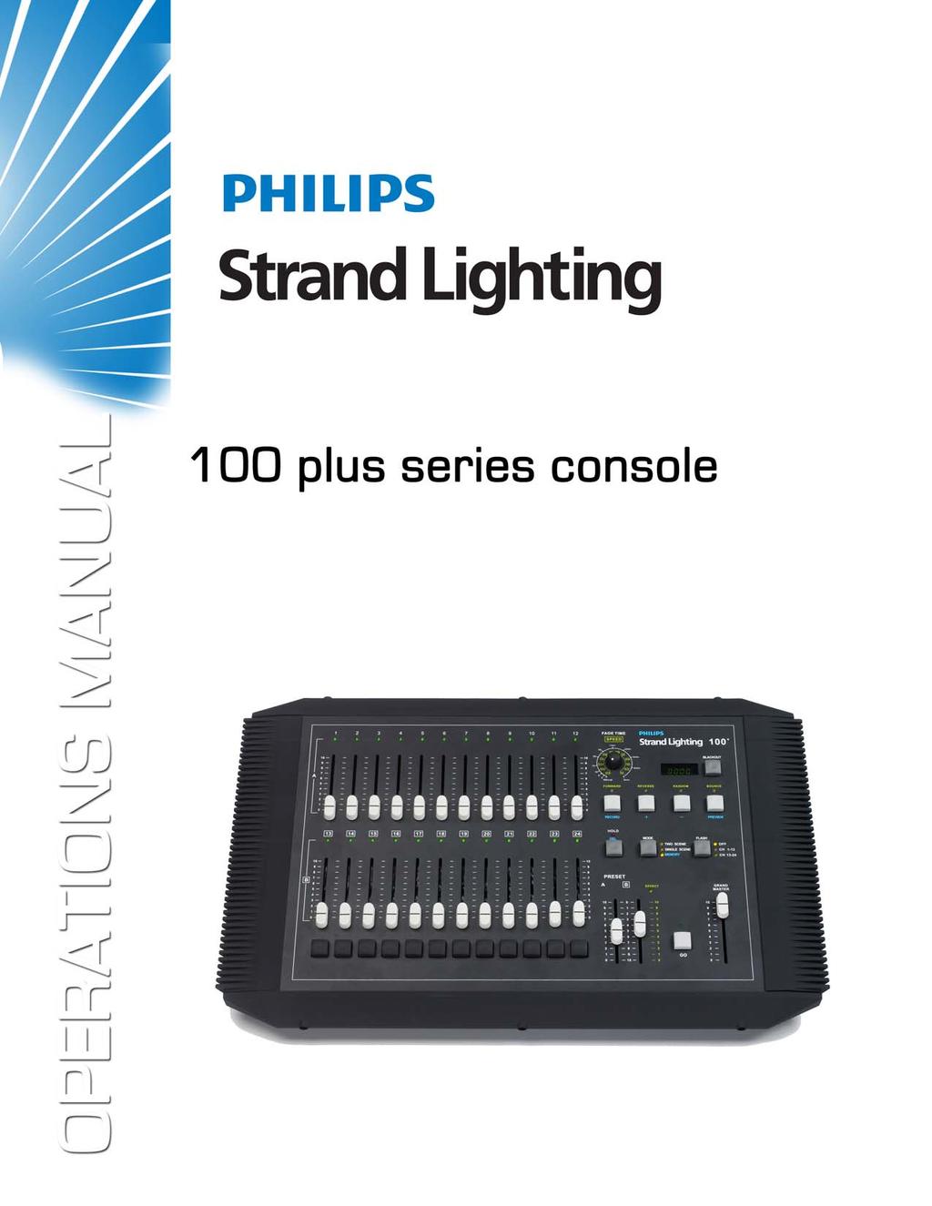
5 Plus Series Console PREFACE. About this Guide The document provides installation and operation instructions for the following product: Plus Series Console Please read all instructions before using this product. Retain this manual for future reference. Additional information for Strand Lighting control consoles including product descriptions may be downloaded at Product Description The Strand series console is a small, simple to use, preset lighting desk. It can either control channels in scene or channels in scenes with the ability to expand scenes with the Hold feature. The console also has the ability to run a single effect. It is also possible to program a single theatrical cue stack of memories and play these back. This console can be rack mounted. For complete technical specifications, see "TECHNICAL SPECIFICATIONS" on page.. Compliance Information Figure : Plus Series Console This equipment is designed and manufactured to comply with international safety standards EC, UL, CS and is intended for use as part of a lighting control system. It must not be used for other purposes where there is a risk of safety to persons. The equipment contains power voltages, socket outlets shall be installed near to the equipment and be easily accessible. All units are CE marked and include UL, cul listed power supplies.. Included Items Working Voltage (Current) Frequency Maximum Ambient Temperature - VAC (A) / - VAC (A) / Hz o C ( o F) - Do not restrict ventilation Unpack the console from the packaging and check that the following components are contained within. If any parts are missing, or damaged, please contact the carrier and your nearest Strand Lighting office. Plus Series Console Universal Power Supply ( to VAC, auto-ranging) Dust cover Operation s Manual (this document) About this Guide
6 s.s.s.s.s s.s s.s s.s s Operations Manual INTRODUCTION. Plus Series Console Layout Figure illustrates the layout of the control features of the Plus Series Console. Effect Forward / Memory Record Channel LED Fade Time / FX Speed Rotary Effect Reverse / Memory Advance Channel Fader LED Display Blackout Button FADE TIME SPEED A min. min. min. BLACKOUT min. Manual min. FORWARD REVERSE RANDOM BOUNCE Effect Random / Memory Back RECORD HOLD DE L MODE TWO SCENE PREVIEW FLASH OFF Effect Bounce / Memory Preview SINGLE SCENE CH - B PRESET A B E FFECT MEMO RY CH - G RAND MASTER Flash Mode Button GO Scene or Memory Mode Hold or Delete Button Fader Flash Button Scene Master "A" Scene Master "B" Go Button Grand Master. Glossary of Terms Figure : Plus Series Console Control Features This section covers some of the common terms used throughout this manual. Grand Master An inhibitive fader that proportionately controls all other faders. This determines maximum output of all faders at all times. The grand master is always active. Playback A An inhibitive fader that proportionately controls all faders for the A scene. Playback B / Effect Master When not running the effect, an inhibitive fader that proportionately controls all faders for the B scene. When running the effect, the fader is a inhibitive master for the effect. INTRODUCTION
7 Plus Series Console Channel Faders A fader that controls the output of the corresponding dimmer number. Fader Flash Button A momentary button that flashes the level of the corresponding fader to full. Which fader is corresponding depends on the setting of the FLASH BUTTON. See below. Mode Button A button that toggles between the three modes of operation of the console. Scene channel mode, Scene channel mode or Memory allows recording and playback of all channels. (In memory Mode all buttons labeled in blue text will perform the functions noted in blue.) Hold Button The Hold button will freeze the output of the faders so that the operator can reset the channel faders for a different look. This is only available in single scene mode. Flash Button Mode Button There are only fader flash buttons and this button toggles the fader flash buttons between OFF, faders - and faders -. Fade Time / Effect Speed Dial When not running the effect, this will allow the operator to set the fade time of the scene masters. When running the effect, this will allow the operator to set the rate at which the effect is running. See the LED display for time / speed readout. Effect Options Buttons These will allow the operator to change the stepping options of the effect. These buttons are only available in Two Scene or Single Scene operation. Refer to Table for more information. Button Name Forward Reverse Random Bounce Table : Effect Buttons Operation / Meaning Forward allows the faders that have a level to step through their appropriate levels from the lowest number fader number to the highest. Reverse allows the faders that have a level to step through their appropriate levels from the highest number fader number to the lowest. Random allows the faders that have a level to step through their appropriate levels in a randomly generated order. Bounce allows the faders that have a level to step through their appropriate levels from the lowest number fader number to the highest then back to the lowest number fader. Memory Options Buttons These buttons will allow for programming and deletion of memories and for access specific numbers in the cue stack. These buttons are only available in Memory Mode. Refer to Table for more information. Button Name Record Operation / Meaning Record allows the current output of the console to be stored into a memory within the cue stack. + "+" (plus) will step the memory number forward by one - "-" (minus) will step the memory number back by one Preview Delete Table : Memory Buttons Preview allows for a specific memory to be previewed. Delete allows for a memory or the whole cue stack to be deleted. Glossary of Terms
8 Operations Manual LED Display This will show alpha / numeric information about the console. Such as fade time, effect step rate, memory number and whether the black out button is active. LED Lights All channel faders have LEDs that mimic the output level of each fader. LEDs also are indicators of the channel mode as well as when all features are activated. All LEDs are green. Black Out Button This will allow the operator to instantly stop all fader output. Press again to restore fader output.. Getting Started After unpacking the console and checking that you have all the included items shipped with your console (refer to "Included Items" on page for details), you may begin connecting your Plus Series Console to power and lighting system. Site Requirements The Plus Series Console requires a sturdy, flat surface for installation (unless the unit is to be rack mounted - see "Rack Mounting" on page for information). The surface should be able to support the weight of the console and should provide suitable ventilation. Also, the site should be clean (i.e. absent of any construction dust or debris) and dry. Before setting up, ensure that the installation site meets these requirements. For operational and space requirements, refer to "TECHNICAL SPECIFICATIONS" on page. Connecting Power The power supply shipped with your Plus Series Console is an auto-ranging, universal voltage supply. It operates between to VAC. To connect the power supply: Step. As shown in Figure, make sure unit s power switch is set to "Off" Step. Connect DC connector from power supply to DC IN on console. Plus Series Console Rear Panel Console On / Off Switch PUSH DMX OUTPUT - Ground - Data - POWER - Data + -VDC,,-NC.A min. ON / OFF RoHS Made in P.R.C. DC Input Connector Pinout to Volts DC. Amps (min.) DC Input (from power supply) Figure : Plus Series Control Console Power Connection Step. When DC connector is plugged in, twist it to lock in place. Step. Connect power supply to AC supply source. Step. Turn on console at Console On / Off Switch. Note: You must connect the console to the lighting system via DMX before it is capable of providing control. See "Connecting DMX" on page for more information. INTRODUCTION
9 min. min. s.s.s s min. s.s.s s min..s.s.s s Manual min. Plus Series Console Connecting DMX The console provides one standard, female XLR -pin connector for connecting to DMX devices. This connector supports one DMX universe of the first channels. Plus Series Console Rear Panel PUSH DMX OUTPUT - Ground - Data - POWER - Data + -VDC,,-NC.A min. ON / OFF RoHS Made in P.R.C. DMX Output Connector DMX Output Connector Pinout Pin Signal Ground Data - Data + No Connection No Connection Figure : Plus Series Control Console DMX Connection Note: For more information on DMX, refer to "Additional Resources for DMX" on page.. Rack Mounting If you wish to mount the Plus Series Console in a rack, using a Philips screwdriver, remove the hardware securing the four side pieces around the console. Use the eight mounting holes (as shown in Figure ) to secure the console in a rack. Note, rack screws are not provided (by others). A FADE TIME SPEED BLACKOUT FORWARD REVERSE RANDOM BOUNCE Rack Mount Mounting Hole (x) RECORD PREVIEW HOLD DE L MODE FLASH TWO SCENE OFF SINGLE SCENE CH - MEMO RY CH - B A PRESET B E FFECT G RAND MASTER GO Figure : Plus Series Console Rack Mounting Note: The Plus Series Console should be rack mounted before power or DMX cables are connected. Rack Mounting
10 Operations Manual. Product Care The Plus Series Console requires very little care and does not have any user-serviceable parts. Avoid spilling liquid on the equipment If this should happen, switch the equipment off immediately at the mains. To reduce the risk of fire or electric shock, do not expose the equipment to rain or moisture. In the event the console needs to be cleaned, remove all power from unit and use only a very mild soap on a damp cloth. Never saturate the console with any cleaning solution. Dry immediately with a soft lint-free cloth after cleaning. WARNING! Never use harsh chemicals or solvents such as window cleaners, paint removers, etc.. Customer Service and Support At Strand Lighting, we are committed to providing you the highest quality in customer service and product support. Whether your needs are telephone troubleshooting assistance or technical service, our full-time staff of experienced professionals are on-hand to provide support. We also have a world-wide network of Authorized Strand Lighting Service Centers. For a complete list of Authorized Strand Lighting Service Centers, please visit our web site at and click on the Support section. For your nearest Strand Lighting office, please see "Strand Lighting Locations" on the inside front cover of this manual. INTRODUCTION
11 Plus Series Console CONSOLE OPERATION. Two Scene Operation When the console is powered up, check the Mode LED indicators to determine the operating mode it is in. Press the Mode button as necessary to place the console in Two Scene Mode. The "Two Scene" LED will illuminate to confirm that the console is in two scene mode as shown in Figure. PREVIEW Mode Button and LED Indicators MODE FLASH TWO SCENE OFF SINGLE SCENE CH - MEMO RY CH - Figure : Mode Button LED Indicator - Two Scene Now, Preset A Master will be the scene master for the top bank of channel faders and Preset B Master will be the scene master for the bottom bank of channel faders. These two banks of faders both correspond to dimmers -. A PRESET B E FFECT G RAND MASTER Preset Masters A / B GO. Manual Crossfades Figure : Preset Master A / B Preset Master A is at full when the fader is in the UP position and at when the fader is in the DOWN position. Preset Master B is just the opposite of Preset Master A. (Refer to the vertical numbering beside the playbacks). This allows for proportional crossfades by moving both faders simultaneously in the same direction. Individual channel fader control works the same in two scene mode as it does in one scene mode. Two Scene Operation
12 Operations Manual. Timed Crossfades For timed crossfades - use the same procedure as the manual crossfade but with the fade timer set to the preferred fade time. The LED display will show the fade time that is set. Timed crossfades can vary from (Manual) to minutes. Fade Time / FX Speed Rotary FADE TIME SPEED min. s.s min. LED Display s.s s.s min. BLACKOUT.s.s.s Manual s.s s min. min.. Single Scene Operation Figure : Preset Master A / B Make sure the MODE button has the console in the single scene mode. Change the mode by pressing the MODE button. The Single Scene LED indicator will illuminate as shown in Figure. HOLD DE L MODE TWO SCENE FLASH OFF SINGLE SCENE CH - MEMO RY CH - Mode Button and LED Indicators A PRESET B E FFECT G RAND MASTER Preset Master A Grand Master Grand Master must be at full to output dimmers to their full potential. GO Figure : Mode Button LED Indicator - Single Scene Make sure the Grand Master and Preset Master A levels are full or at the desired level. Once the masters are set, simply set the Channel Faders ( - ) to the desired levels. At this point, the dimmers should correspond to the level of the Channel Faders. The fader output of the fader that is being adjusted will be shown in the LED Display on a scale from to. CONSOLE OPERATION
13 Plus Series Console. Hold In single scene mode only, using the HOLD button (as shown in Figure ) allows the operator to freeze all dimmer output and manually reset the levels for all faders to create a different look. RECORD PREVIEW HOLD Hold Button DE L MODE FLASH OFF CH - CH - TWO SCENE SINGLE SCENE MEMO RY Figure : Hold Button - Single Scene Mode To use Hold Button Operation Step. Select current settings with channel faders. Make sure Preset Master A is at "" and Preset Master B is at "" (zero). Note: The hold feature can only be activated and deactivated with playbacks in these positions. Step. Press the HOLD button. The HOLD LED indicator should be illuminated. The current settings will now be recorded into the HOLD's memory. Step. You can now set the channels to the levels required for the next cue. The channel levels will not output as live. Step. You can now move Preset Master A to "" (zero) while moving Master Preset B level to. During the crossfade, the HOLD LED will be flashing. The new cue will output and the previous cue will fade out. Step. Once both Preset Master A and Preset Master B have reached the bottom of the current Channel Fader settings, they will now be recorded into HOLD's memory. Note, the HOLD LED will stop flashing but remain on indicating the activation of the HOLD feature. Step. The operator is now free to reset all Channel Faders to the levels for the next cue. Once the channel faders are set, crossfade Preset Master A back to and Preset Master B back to. During crossfade operation, the hold LED will flash. After the crossfade is complete, the new cue will now be outputting live and locked into HOLD's memory. Note, the HOLD LED should still be illuminated. Step. You can now repeat the above steps to continue crossfading between cues. Step. Press HOLD button again to release the HOLD function when Preset Master A and Preset Master B faders are at the top. After pressing HOLD, the HOLD LED should turn off. Note: For timed crossfades - use the same procedure as the manual crossfade but with the fade timer set to the preferred fade time. The LED display will show the fade time that is set.. Effect - Single Scene Mode An effect is a way to get fast changing output of dimmer levels in a specific order. The effect capability of this console is limited but simple to do. The console can run one effect at a time. Set the console to single scene mode. Set Preset Master A to (Down) and Preset Master B to (Up). Preset Master B will become the effect master. (See the colored information beside the Playback B). Set current fader levels to include only the faders that will be in the effect. Set them to any level from to. Hold
14 Operations Manual Press one of the Effect buttons - Forward, Reverse, Random, or Bounce. Manual min. FORWARD REVERSE RANDOM BOUNCE Effect Buttons RECORD PREVIEW HOLD DE L MODE TWO SCENE SINGLE SCENE MEMO RY FLASH OFF CH - CH - Figure : Hold Button - Single Scene Mode Table provides details of each Effect Button s operation. Button Name Forward Reverse Random Bounce Operation / Meaning Forward allows the faders that have a level to step through their appropriate levels from the lowest number fader number to the highest. Reverse allows the faders that have a level to step through their appropriate levels from the highest number fader number to the lowest. Random allows the faders that have a level to step through their appropriate levels in a randomly generated order. Bounce allows the faders that have a level to step through their appropriate levels from the lowest number fader number to the highest then back to the lowest number fader. The lights will now operate a chase in the selected Effect mode. The Effect Master will inhibit the levels of all effect channels. The fade time rotary becomes the SPEED dial. Set the speed of the effect as desired. The LED Display will show the set rate. The effect can be faded in rather than the effect starting abruptly by pulling down the Effect Master and fading it up at the appropriate time.. Effect - Two Scene Mode Table : Effect Buttons To run the effect in two scene mode, just change the MODE Button to two scene. Once the LED indicator illuminates "Two Scene", the console is set to two scene mode. Now all of the fader levels from the top fader bank will become the faders in the effect. With both playbacks in the up position, just press any of the effect directional buttons and the effect will start immediately. Once the effect is running, adding new fader levels will add those faders into the effect. Note: Only the faders in the top fader bank can be used in the effect. Press the effect button again to stop. CONSOLE OPERATION
15 Plus Series Console. Memory Operation Memory mode allows you to program a cue stack of up to memories. These can be played back sequentially. In memory mode the buttons labeled in blue will be available. s s.s.s s min..s BLACKOUT.s.s.s Manual s s.s min. min. FORWARD REVERSE RANDOM BOUNCE LED Display RECORD PREVIEW HOLD Memory Buttons DE L MODE TWO SCENE FLASH OFF SINGLE SCENE CH - MEMO RY CH - Mode Button Figure : Hold Button - Single Scene Mode To set the console to Memory Mode: Step. Make sure the MODE Button is set to Memory mode. Change the mode by pressing the MODE button. "Memory Mode" LED indicator will illuminate once the console is set to Memory Mode. Step. The LED Display will show ":". Step. The first two digits will be the currently outputting memory and the second two digits will be the next available memory. In this case (as shown to the right) there are no memories recorded. Record Mode To enter record mode hold down the MODE Button while in Memory mode and then press the RECORD button. The Memory LED will blink to show you are in Record mode. The LED Display will show, "SS:". The "SS" signifies an unrecorded or scene, "SP" signifies a recorded scene. You can now set the channel faders to the levels you require for the first cue. When the cue is as desired, press the RECORD Button. This will store the scene. The display will automatically increment by one. If you wish to change the number use the [ + ] or [ - ] buttons. These will increment or decrease the memory numbers. When you have recorded your cues press the MEMORY button again. The LED will stop blinking and the LED Display will show, ":". Memory Operation
16 Operations Manual Playback Mode After recording cues into the console memory, you can play them back. There are two methods, one using the GO button (Flash Mode Button) and the other using the Preset Master A and Preset Master B. Go Button Playback Use the [ + ] button to take you to the memory that you wish to begin with. For instance memory. The display shows that there is currently no memory outputting and that the next memory is. To play this back press the Go button. Memory will output and the next available memory will be displayed, in this case Memory. If you wish to play back a different memory next you can use the [ + ] or [ - ] buttons to select it. When you reach the last recorded memory it will select the first recorded memory as the next cue. Only memories that have been recorded will be played back. If you have recorded,,,, when you playback the memory stack these will be the five memories that will playback in sequence. Timed Playback It is possible to use times when playing back the memories. Before you press the GO button use the Fade Time rotatory dial to set the time. The time will be shown on the LED Display. When you press the GO button the time selected will be used. The LED above the GO button will flash while the transition is happening. Preset Playback of Memories. While in memory mode if you move the Preset Master A and Preset Master B faders, the memory that is next to be output will be faded in and the current memory will be faded out. You can manually control the fade time by using this method. For example if the Preset Master A and Preset Master B faders are at the top and the LED Display will show, ":". Then moving the Preset Master A and Preset Master B faders to the bottom will fade Memory out and fade Memory in. Timed Playback It is possible to use times when playing back the memories. Before you move the Preset Master A and Preset Master B faders use the Fade Time rotatory dial to set the time. The time will be shown on the LED Display. When you move the faders the transition will happen over the time set. The EFFECT LED will flash to show a timed transition is happening. It is possible to switch between the two playback modes at any time either by moving the Preset Master A and Preset Master B faders or pressing the GO button.. Deleting Memories You can delete either a single memory or all of the memories recorded in the console. Single Memory Deletion Select Record function by pressing the RECORD button while holding down the MEMORY button. The MEMORY button s LED indicator will blink. Use the [ + ] or [ - ] buttons to select memory you wish to delete. CONSOLE OPERATION
17 Plus Series Console Press the DELETE button for seconds. This will delete the currently selected memory it will change from an "SP" to "SS". You can continue to the next memory you wish to delete. All Memory Deletion Select Record function by pressing the RECORD button while holding down the MEMORY button. The MEMORY button s LED indicator will blink. Use the [ + ] or [ - ] buttons to select any recorded memory. Press the DELETE button for seconds. This will delete the currently selected memory it will change from an "SP" to "SS". While continuing to hold the DELETE button press and hold the RECORD button for seconds. This will delete the all the recorded memories.. Preview Recorded Memories Note: Preview is a mode that displays what the memory (see "LED Display" on page ) is outputting. [ + ] and [ - ] allow you to step through the stored memories in a very quick fashion (without fades) to allow you to preview the show. This mode will allow you to rapidly step through all the memories that you have recorded. Select Record function by pressing the RECORD button while holding down the MEMORY button. The MEMORY button s LED indicator will blink. Press the PREVIEW button. You can step through the memories using the [ + ] or [ - ] buttons. The LED Display will show, "Pr:". To exit Preview mode press the RECORD button once. To return to Memory mode press the MEMORY button. Preview Recorded Memories
18 Operations Manual TECHNICAL SPECIFICATIONS. Electrical Supply Voltage: Universal power supply -V Approvals: CE marked with UL listed and cul power supply Connectivity: DMX Out (XLRF) port. Mechanical Construction: Rigid folded sheet steel and Flame retardant ABS controls Operating Temperature: to C / to F ambient Humidity: % - % non-condensing Storage Temperature: to C / to F Weight:. lbs /. kgs Dimensions (LxWxH):. x. x. in /. x. x. mm. in ( mm). in ( mm). in ( mm) TECHNICAL SPECIFICATIONS
19 Plus Series Console NOTES Mechanical
20
Strand Lighting Inc Darin Way, Cypress, CA 90630, USA Tel: Fax:
 Strand Lighting Inc. 6603 Darin Way, Cypress, CA 90630, USA Tel: +1 714 230 8200 Fax: +1 714 230 8173 Strand Lighting Europe Ltd. Unit 2, Royce Road, Fleming Way, Crawley, West Sussex. United Kingdom Tel:
KALEIDOSCOPE. Effects & Colour Control Software for GENIUS. Operator's Manual
 KALEIDOSCOPE Effects & Colour Control Software for GENIUS Operator's Manual Document No.: 85021 (A86) Issue: 2 Date: June 1994 Offices and Service Centres Asia: Canada: France: Germany: Italy: U.K: USA:
 QuickStart Guide Showline Offices Dallas 10911 Petal Street Dallas, TX 75238 Tel: +1 214-647-7880 Fax: +1 214-647-8030 Auckland 19-21 Kawana Street Northcote, Auckland 0627 New Zealand Tel: +64 9 481 0100
10911 Petal Street Kawana Street Dallas, TX Northcote, Auckland Fax: Tel: Fax:
 SL LEDSPOT 300 Luminaire Quickstart Guide Showline Offices Dallas Auckland 10911 Petal Street 19-21 Kawana Street Dallas, TX 75238 Northcote, Auckland 0627 Tel: +1 214-647-7880 New Zealand Fax: +1 214-647-8030
Philips Strand Lighting Offices
 Philips Strand Lighting Offices Philips Strand Lighting - Dallas 10911 Petal Street Dallas, TX 75238 Tel: 214-647-7880 Fax: 214-647-8031 Philips Strand Lighting - Asia Limited Unit C, 14/F, Roxy Industrial
FOREWORD January
 FOREWORD 02.9692.0010 0 14 January 2011 0 PHILIPS SELECON PL1 LED LUMINAIRE SERVICE MANUAL Forward The material in this manual is for information purposes only and is subject to change without notice.
Strand Lighting Offices Philips Strand Lighting - Dallas Petal Street Dallas, TX Tel: Fax:
 Strand Lighting Offices Philips Strand Lighting - allas 10911 Petal Street allas, TX 75238 Tel: 214-647-7880 Fax: 214-647-8031 Philips Strand Lighting - sia Limited Unit, 14/F, Roxy Industrial entre No.
Lighting Control Software. Operator's Manual
 Lighting Control Software Operator's Manual Offices and Service Centres Asia: Canada: France: Germany: Italy: U.K: USA: 7th Floor Corporation Sq., 8 Lam Lok St.,Kowloon Bay, Kowloon, Hong Kong Tel: (852)
Showline Offices Dallas Petal Street Dallas, TX Tel: Fax:
 Showline Offices Dallas 10911 Petal Street Dallas, TX 75238 Tel: +1 214-647-7880 Fax: +1 214-647-8030 Asia Unit C, 14/F, Roxy Industrial Centre No. 41-49 Kwai Cheong Road Kwai Chung, N.T., Hong Kong Tel:
INSTALLATION & USER S MANUAL
 Lighting BRINGING IMAGINATION TO LIGHT INSTALLATION & USER S MANUAL 20160601 Pegasus Installation Manual Corporate Offices: 57 Alexander Street Yonkers, NY 10701 (914)-476-7987 www.altmanlighting.com The
SR - 516D DESK TOP DMX REMOTE STATION. Version: Date: 05/16/2013
 SR - 516D DESK TOP DMX REMOTE STATION Version: 1.10 Date: 05/16/2013 Page 2 of 10 TABLE OF CONTENTS DESCRIPTION 3 POWER REQUIREMENTS 3 INSTALLATION 3 CONNECTIONS 3 POWER CONNECTIONS 3 DMX CONNECTIONS 3
Commander 384. w w w. p r o l i g h t. c o. u k U S E R M A N U A L
 Commander 384 w w w. p r o l i g h t. c o. u k U S E R M A N U A L 1, Before you begin 1.1: Safety warnings...2 3 1.2: What is included...4 1.3: Unpacking instructions...4 2, Introduction 2.1: Features...4
CommuniquéPro Operator s manual
 CommuniquéPro Operator s manual Communications software For GeniusPro & Lightpalette v2.1 and later Document Number: 40/B731 Issue: 3.0 Date: 19 Jan 98 Offices And Service Centres Phone numbers do not
TL MEMORY CONTROL CONSOLE OWNERS MANUAL 02/17/2005. Version 0.6
 TL - 3012 MEMORY CONTROL CONSOLE OWNERS MANUAL Version 0.6 02/17/2005 Page 2 of 6 SPECIFICATIONS Channels: 12 Operating modes: Two Scene Manual Mode Preset Scene Playback Mode Chase Mode Output connector:
DMX Operator 192-channel lighting controller
 USER MANUAL DMX Operator 192-channel lighting controller CAUTION! Keep this device away from rain and moisture! Unplug mains lead before opening the housing! For your own safety, please read this user
Controller DMX DC-1224
 Manual Controller DMX DC-1224 Table of Contents 1. Safety instructions... 4 1.1. FOR SAFE AND EFFICIENT OPERATION... 4 3. Overview... 6 3.1. Front view... 6 3.2. Rear view... 9 4. Operation guide... 10
192 Channel DMX Controller
 DM-X 92 Channel DMX Controller USER MANUAL 54. 9UK Vers ion. D M X 5 2 C O N T R O L L E R S E R I E S Content. Before you begin. What is included.......2 Unpacking instructions....3 Safety instructions...
DMX DC User manual. DMX controller
 User manual Musikhaus Thomann Thomann GmbH Hans-Thomann-Straße 1 96138 Burgebrach Germany Telephone: +49 (0) 9546 9223-0 E-mail: info@thomann.de Internet: www.thomann.de 17.08.2018, ID: 216405 Table of
HDMI 5x1 Switch B-240-HDSWTCH-5X1 INSTALLATION MANUAL
 HDMI 5x1 Switch B-240-HDSWTCH-5X1 INSTALLATION MANUAL IMPORTANT SAFETY INSTRUCTIONS To reduce the risk of fire or electric shock, read and follow all instructions and warnings in this manual. Keep this
DMX48. User s instruction manual. 24 Channel DMX controller
 WWW.LIGHTEMOTIONS.COM.AU DMX48 24 Channel DMX controller User s instruction manual This manual contains important information about the safe installation and use of this product Please read this instruction
DMX DC User manual. DMX controller
 User manual Musikhaus Thomann Thomann GmbH Hans-Thomann-Straße 1 96138 Burgebrach Germany Telephone: +49 (0) 9546 9223-0 E-mail: info@thomann.de Internet: www.thomann.de 20.04.2018, ID: 346647 Table of
USER GUIDE 8-CHANNEL DMX CONTROLLER December 2013 Version 1.0 CHASE / STROBE SPEED FADE SPEED RED GREEN BLUE WHITE AMBER DIMMER INSERT
 8-CHANNEL DMX CONTROLLER RED GREEN BLUE YELLOW 1 2 3 4 5 6 CYAN ORANGE PURPLE WHITE RED GREEN BLUE WHITE AMBER DIMMER RECORD INSERT DELETE TAP CLEAR MANUAL MUSIC 1 2 3 5 6 7 AUTO CHASE / STROBE SPEED 4
LIGHT COPILOT II. elationlighting.com Internet:
 LIGHT COPILOT II E-mail: info@ elationlighting.com Internet: http://www.elationlighting.com 1 Introduction Thank you for your purchase of the LIGHT COPILOT II. The LIGHT COPILOT II is an intelligent lighting
ALO 030 MKII. 30 Watt DMX LED scanner. User manual
 ALO 030 MKII 30 Watt DMX LED scanner User manual Safety instructions WARNING! Always keep this device away from moisture and rain! Hazardous electrical shocks may occur! WARNING! Only connect this device
STAGE SETTER-8. User Instructions. Elation Professional 4295 Charter Street Los Angeles Ca
 Introduction STAGE SETTER-8 User Instructions Introduction: Thank you for purchasing the Elation Professional Stage Setter 8. To optimize the performance of this product, please read these operating instructions
Selecon LED Fixtures. PL3 LED Luminaire. Features SPECIFICATION SUBMITTAL
 A revolutionary breakthrough in stage and studio lighting, the PL3 LED Luminaire delivers full control of the beam color composition irrespective of intensity. Drawing on technology and specific insight,
RD RACK MOUNT DIMMER OWNERS MANUAL VERSION /09/2011
 RD - 122 RACK MOUNT DIMMER OWNERS MANUAL VERSION 1.3 03/09/2011 Page 2 of 14 TABLE OF CONTENTS UNIT DESCRIPTION AND FUNCTIONS 3 POWER REQUIREMENTS 3 INSTALLATION 3 PLACEMENT 3 POWER CONNECTIONS 3 OUTPUT
Mini LED Pin Spot Light Model: PLS00571
 Mini LED Pin Spot Light Model: PLS00571 1 Please read these instructions carefully before use and retain for future reference. IMPORTANT SAFETY INFORMATION When using electrical appliances basic safety
FD Trinitron Colour Television
 R 4-205-569-32(1) FD Trinitron Television Instruction Manual GB KV-14LM1U 2000 by Sony Corporation NOTICE FOR CUSTOMERS IN THE UNITED KINGDOM A moulded plug complying with BS1363 is fitted to this equipment
SCENEMASTER 3F QUICK OPERATION
 SETTING PRESET MODE SCENEMASTER 3F QUICK OPERATION 1. Hold [RECORD], and press [CHNS] (above the Channels Master) to set Scenes, Dual, or Wide mode. WIDE MODE OPERATION In Wide mode, both CHANNELS and
4-PROJECTOR BAR WITH 3 X 9W LEDS AND 1 X 1W FLASH LED USER GUIDE
 4-PROJECTOR BAR WITH 3 X 9W LEDS AND 1 X 1W FLASH LED USER GUIDE 10482 - Version 1 / 04-2016 English LIVESET - LIVESET - 4-Projector bar with 3 x 9W LEDs and 1 x 1W Flash LED 1 - Safety information Important
DMX-LINK QUICK OPERATION
 DMX-LINK QUICK OPERATION RESETTING THE CURRENT PATCH TO A ONE-TO-ONE OR ZERO PATCH The current Patch List may be initialised as a One-to-One or Zero patch as follows: 1. Ensure the Record LED is on. If
DMX192S Controller INSTRUCTION MANUAL. Ref. nr.: V2.1
 DMX192S Controller Ref. nr.: 154.060 INSTRUCTION MANUAL V2.1 2 ENGLISH Congratulations to the purchase of this Beamz product. Please read this manual thoroughly prior to using the product in order to benefit
SATRI AMPLIFIER AMP-51R. Owner s Manual
 SATRI AMPLIFIER AMP-51R Owner s Manual contents SAFETY INSTRUCTIONS 4 INTRODUCTION 6 OVERVIEW (FRONT PANEL) 8 OVERVIEW (REAR PANEL) 9 OVERVIEW (REMOTE CONTROL) 1 1 OPERATION 12 TROUBLESHOOTING 13 SPECIFICATION
Power Injector 1520 Series
 Power Injector 1520 Series Technical Specifications Input voltage 100 to 240 VAC Output voltage 56.0 VDC Voltage range tolerance 54 VDC to 57 VDC Maximum current 1.43 A No load current 15 ma 56VDC@0.71A
TL5024 MEMORY LIGHTING CONSOLE OWNERS MANUAL. Version 1.01
 TL5024 MEMORY LIGHTING CONSOLE OWNERS MANUAL Version 1.01 09/22/2017 Page 2 of 14 SPECIFICATIONS Total channels Operating modes Scene memory Chase 12 or 24 depending on mode 12 channels x 2 manual scenes
VERSION 2.A 10/21/1999. Lightronics Inc. 509 Central Drive, Virginia Beach, VA TEL
 7/ 0(025< /,*+7,1*&21752/ &2162/( 2:1(56Ã0$18$/ VERSION 2.A 10/21/1999 Contents DESCRIPTION OF CONTROLS 3 OPERATION 4 USING THE MENU SYSTEM 5 MENU FUNCTIONS 5 RECORDING SCENES 7 USING SCENES 8 RECORDING
HDBaseT RECEIVER B-540-RX-330-IR INSTALLATION MANUAL
 HDBaseT RECEIVER B-540-RX-330-IR INSTALLATION MANUAL IMPORTANT SAFETY INSTRUCTIONS To reduce the risk of fire or electric shock, read and follow all instructions and warnings in this manual. Keep this
HDBaseT RECEIVER B-520-RX-230-IR INSTALLATION MANUAL
 HDBaseT RECEIVER B-520-RX-230-IR INSTALLATION MANUAL IMPORTANT SAFETY INSTRUCTIONS To reduce the risk of fire or electric shock, read and follow all instructions and warnings in this manual. Keep this
HDBaseT RECEIVER B-520-RX-330-IR INSTALLATION MANUAL
 HDBaseT RECEIVER B-520-RX-330- INSTALLATION MANUAL IMPORTANT SAFETY INSTRUCTIONS To reduce the risk of fire or electric shock, read and follow all instructions and warnings in this manual. Keep this manual
DisplayPort Extender over 2 LC Fibers
 DisplayPort Extender over 2 LC Fibers Audio 3GSDI Embedder EXT-DP-CP-2FO User Manual Release A2 DisplayPort Extender over 2 LC Fibers Important Safety Instructions 1. Read these instructions. 2. Keep these
LED-PAR200B USER MANUAL. COLORsplash 200B
 LED-PAR00B COLORsplash 00B USER MANUAL CHAUVET, 3000 N 9 th Ct, Hollywood, FL 3300 U.S.A (800) 76-084 (954) 99-5 FAX (954) 99-5560 www.chauvetlighting.com 006-07-06/0:3 TABLE OF CONTENT TABLE OF CONTENT...
DisplayPort Extender over 2 LC Fibers
 DisplayPort Extender over 2 LC Fibers Audio 3GSDI Embedder EXT-DP-CP-2FO User Manual Release A2 DisplayPort Extender over 2 LC Fibers Important Safety Instructions 1. Read these instructions. 2. Keep these
Tube Roller Shakers. User Guide. Version 1.2
 Tube Roller Shakers User Guide Version 1.2 Control panel Rollers Side retaining panels Analog models LED display Drip tray (not visible) Digital models Power On/Off and control dial Roller retaining panel
Personal Q Guide for VENUE Systems
 Personal Q Guide for VENUE Systems Version 1.0 Digidesign 2001 Junipero Serra Boulevard Daly City, CA 940-3886 USA tel: 650 731 6300 fax: 650 731 6399 Technical Support (USA) tel: 650 731 6100 fax: 650
MANUAL ENGLISH Core Club Ordercode: D2314
 MANUAL ENGLISH Core Club Ordercode: Highlite International B.V. Vestastraat 2 6468 EX Kerkrade the Netherlands Table of contents Warning... 2 Unpacking Instructions... 2 Safety Instructions... 2 Operating
2002 Martin Professional A/S, Denmark.
 Freekie user manual 2002 Martin Professional A/S, Denmark. All rights reserved. No part of this manual may be reproduced, in any form or by any means, without permission in writing from Martin Professional
KingWash 7QX 7x40w,Zoom 5-60degree. User manual. Please read the instructions carefully before use TABLE OF CONTENTS
 KingWash 7QX 7x40w,Zoom 5-60degree User manual Please read the instructions carefully before use TABLE OF CONTENTS 1. Safety Instructions... 2 2. Technical Specifications... 4 3. How To Control The Unit...
SquareLED - Aura Bar & Matrix Beam Light 100
 SquareLED - Aura Bar & Matrix Beam Light 100 1. SAFETY INSTRUCTIONS Please read these instructions carefully they include the important information about the installation usage and maintenance of this
FiliBuster. User Manual
 FiliBuster User Manual Unit 1A 126 Great North Road Hatfield, Hertfordshire AL9 5JN UK Tel: +44 (0) 1462 600101 Email: moreinfo@interspaceind.com www.interspaceind.com Cueing and Presentation Control Specialists
Owner s Manual LED COMMANDER 16/2
 Owner s Manual LED COMMANDER 16/2 Content Introduction...2 Technical Specification...2 Maintenance and care...2 Notes on safety...3 Features...4 Overview...5 Installation...6 Operation...6 Channel Assignment...7
Page 1 of 6 FXLD618FRP2I4 LED FIXTURE Version 0.2 OWNERS MANUAL 10/04/17
 Page 1 of 6 FEATURES AND SPECIFICATIONS LEDS: 18, 6W each (Warm White, Cool White, 2in1) Beam angle: 25º or 45 Control system: DMX512 + Stand Alone Modes DMX channels: 1/2/3/4/5 DMX connectors: 3 pin XLR
DMX DC-192. User manual. DMX controller
 User manual Musikhaus Thomann Thomann GmbH Hans-Thomann-Straße 1 96138 Burgebrach Germany Telephone: +49 (0) 9546 9223-0 E-mail: info@thomann.de Internet: www.thomann.de 08.11.2017, ID: 391103 Table of
6X3W RGB LEDS PROJECTOR FOR PROFESSIONAL TRUSSES USER GUIDE / Version 1
 6X3W RGB LEDS PROJECTOR FOR PROFESSIONAL TRUSSES USER GUIDE 10364-07-2015 / Version 1 English MINITRUSS-6TCb - 6x3W RGB LEDs projector for professional trusses 2 MINITRUSS-6TCb - 6x3W RGB LEDs projector
TVAC20000 User manual
 TVAC20000 User manual Version 01/2010 Original English user manual. Keep for future use. 10 Introduction Dear Customer, Thank you for purchasing this product. This product meets the requirements of the
6X3W TRICOLOUR LEDS COMPACT PROJECTOR
 6X3W TRICOLOUR LEDS COMPACT PROJECTOR USER GUIDE 10147 - Version 2 / 05-2015 English MINICUBE-6TCb - 6x3W tricolour LEDs compact projector 1 - Safety information Important safety information This unit
Marshall Electronics. Pro A/V Communications VMV-402-SH. 3G/HD/SD-SDI Quad-viewer/Switcher with Audio Meter Display. User Manual.
 Marshall Electronics Pro A/V Communications VMV-402-SH 3G/HD/SD-SDI Quad-viewer/Switcher with Audio Meter Display User Manual Table of Contents 1. Introduction... 3 2. Features... 3 3. Package Contents...
LED-BANK4 USER MANUAL. COLORbank 4
 LED-BANK4 COLORbank 4 USER MANUAL CHAUVET, 3000 N 29 th Ct, Hollywood, FL 33020 U.S.A (800) 762-084 (954) 929-5 FAX (954) 929-5560 www.chauvetlighting.com 2006-04-8/6:44 Table of Content BEFORE YOU BEGIN...
Operator s Manual. Ultegra. Health Scale. Fairbanks Scales by Fairbanks Scales Inc. All rights reserved. Revision 5 06/07
 Operator s Manual Ultegra Health Scale Fairbanks Scales 2007 by Fairbanks Scales Inc. All rights reserved 50735 Revision 5 06/07 Amendment Record Ultegra Health Scale 50735 Manufactured by Fairbanks Scales
9X9W LEDS BLINDER WITH LCD DISPLAY USER GUIDE December 2013 Version 1.12
 9X9W LEDS BLINDER WITH LCD DISPLAY USER GUIDE 10133 - December 2013 Version 1.12 1 - Safety information Important safety information This unit is intended for indoor use only. Do not use it in a wet, or
HDBaseT EXTENDER B-540-EXT-230-RS INSTALLATION MANUAL
 EXTENDER B-540-EXT-230-RS INSTALLATI MANUAL IMPORTANT SAFETY INSTRUCTIS To reduce the risk of fire or electric shock, read and follow all instructions and warnings in this manual. Keep this manual for
Colour Control48 Order Code: Control48
 Colour Control48 Order Code: Control48 www.cobrainternational.com User Manual Cobra Colour Control 48 Dear Customer, Thank you for purchasing the Cobra Colour Control 48. With decades of experience in
TS2.8 Sub OWNER S MANUAL
 TS2.8 Sub OWNER S MANUAL TS2.8 Sub CONTENTS IMPORTANT SAFETY INSTRUCTIONS 03 WARNINGS 03 FUSE PROTECTION 04 WARNING: STRONG MAGNETIC FIELD 04 EMC / EMI 04 ECODESIGN STANDBY POWER CONSUMPTION 04 WARRANTY
Snapshot. Obey 10 DMX Controller USER MANUAL
 Obey 10 DMX Controller Snapshot Ok on Dimmer Outdoor OK Sound Activated DMX512 Master/Slave 115V/230V Switch Replaceable Fuse User Serviceable Duty Cycle USER MANUAL Chauvet, 3000 N 29 th Ct, Hollywood,
ENGLISH Scanmaster 2 MKII
 MANUAL ENGLISH Scanmaster 2 MKII V1 Highlite International B.V. Vestastraat 2 6468 EX Kerkrade the Netherlands Table of contents Warning...2 Safety Instructions...2 Operating Determinations...3 Connection
ACUBRITE 23 SS. Manual. Stainless Steel Chassis 23" LCD Display. Content
 ACUBRITE 23 SS Stainless Steel Chassis 23" LCD Display Manual Introduction... 2 Hardware Installation... 2 The Display Timing... 5 The Display Outline Dimensions... 6 The Display Controls... 7 The Screen
Operating Manual. Automated Gear. Apollo Design Technology, Inc Fourier Drive Fort Wayne, IN USA
 Operating Manual Automated Gear Apollo Design Technology, Inc. 4130 Fourier Drive Fort Wayne, IN 46818 USA PH: +01(260)497-9191 FX: +01(260)497-9192 www.apollodesign.net 11-25-09 5-6 POWERING UP THE RIGHT
KONTROL channels DMX controller USER MANUAL. For safety, please read this user manual carefully before initial use.
 KONTROL192 192 channels DMX controller USER MANUAL For safety, please read this user manual carefully before initial use. Event Lighting reserves the right to revise the manual at any time. Information
Spectra Batten (Order code: LEDJ95)
") www.prolight.co.uk Spectra Batten (Order code: LEDJ95) Safety WARNING FOR YOUR OWN SAFETY, PLEASE READ THIS USER MANUAL CAREFULLY BEFORE YOUR INITIAL START-UP! CAUTION! Keep this equipment away from rain,
www.prolight.co.uk Spectra Batten (Order code: LEDJ95) Safety WARNING FOR YOUR OWN SAFETY, PLEASE READ THIS USER MANUAL CAREFULLY BEFORE YOUR INITIAL START-UP! CAUTION! Keep this equipment away from rain,
Selecon LED Fixtures. PL3 LED Luminaire. Features SPECIFICATION SUBMITTAL
 A revolutionary breakthrough in stage and studio lighting, the PL3 LED Luminaire delivers full control of the beam colour composition irrespective of intensity. Drawing on technology and specific insight,
USER INSTRUCTIONS MODEL CSI-200 COAXIAL SYSTEM INTERFACE
 USER INSTRUCTIONS MODEL CSI-200 COAXIAL SYSTEM INTERFACE 9350-7676-000 Rev B, 5/2001 PROPRIETARY NOTICE The RTS product information and design disclosed herein were originated by and are the property of
User's Manual No Rev 1.0
 User's Manual No. --1 Rev 1. Welcome Thanks for your purchasing this Lite- Pro lighting control equipment. This product has the following listed main features: Ch. dimming console with dimming faders,
Instruction Manual AVT-8710 Time Base Corrector
 99 Washington Street Melrose, MA 02176 Phone 781-665-1400 Toll Free 1-800-517-8431 Visit us at www.testequipmentdepot.com Instruction Manual AVT-8710 Time Base Corrector Table of Contents 1.0 Introduction
TABLE OF CONTENTS. Page 2 of 16 COLORband PiX IP User Manual (Rev. 1)
") User Manual TABLE OF CONTENTS 1. Before You Begin...3 What Is Included... 3 Unpacking Instructions... 3 Claims... 3 Text Conventions... 3 Icons... 3 Disclaimer... 3 Product at a Glance... 4 Safety Notes...
User Manual TABLE OF CONTENTS 1. Before You Begin...3 What Is Included... 3 Unpacking Instructions... 3 Claims... 3 Text Conventions... 3 Icons... 3 Disclaimer... 3 Product at a Glance... 4 Safety Notes...
Tube Rotator. User Guide. Version 1.2
 Tube Rotator User Guide Version 1.2 Figure 1: Fixed Speed Model Tube holder spindle Tilt adjustment wheel IEC power inlet socket (at rear) Power on/off switch Figure 2: Variable Speed Model Tube holder
Led Dynamic DMX Tri Curtain Manual
 Led Dynamic DMX Tri Curtain Manual Welcome to use the LED dynamic DMX Tri curtain, please read following Safety Notes as well as those in User Manual carefully before connection, installing, operation
MANUAL ENGLISH Showmaster 48 MKII V1 Ordercode: 50831
 MANUAL ENGLISH Showmaster 48 MKII V1 Highlite International B.V. Vestastraat 2 6468 EX Kerkrade the Netherlands Table of contents Warning... 2 Safety Instructions... 2 Operating Determinations... 3 Connection
User Guide. Single-Link DVI Active Cable Extender. DVI-7171c
 User Guide Single-Link DVI Active Cable Extender DVI-7171c TABLE OF CONTENTS SECTION PAGE PRODUCT SAFETY...1 PRODUCT LIABILITY...1 1.0 INTRODUCTION...2 2.0 SPECIFICATIONS...3 3.0 PACKAGE CONTENTS...4 4.0
OSO 1612 operator. DMX controller. User manual
 OSO 1612 operator DMX controller User manual Safety instructions WARNING! Always keep this device away from moisture and rain! Hazardous electrical shocks may occur! WARNING! Only connect this device to
PLAYMATE PROFESSIONAL STEREO 19 MIXER, USB/SD CARD AND BLUETOOTH PLAYER. User Guide and Reference Manual. page 1
 PLAYMATE PROFESSIONAL STEREO 19 MIXER, USB/SD CARD AND BLUETOOTH PLAYER User Guide and Reference Manual page 1 INTRODUCTION Congratulations and thank you for purchasing the NewHank Playmate mixer. This
User Guide. HDMI Active Cable Extender. DVI-7370c
 User Guide HDMI Active Cable Extender DVI-7370c TABLE OF CONTENTS SECTION PAGE PRODUCT SAFETY...1 PRODUCT LIABILITY STATEMENT........................ 1 1.0 INTRODUCTION...2 2.0 SPECIFICATIONS...3 3.0 PACKAGE
Outdoor Stage PAR 12 3W Tri LED PAR. user manual
 Outdoor Stage PAR 12 3W Tri LED PAR user manual Musikhaus Thomann Thomann GmbH Hans-Thomann-Straße 1 96138 Burgebrach Germany Telephone: +49 (0) 9546 9223-0 E-mail: info@thomann.de Internet: www.thomann.de
SM-8/2 ORDERCODE 50700
 SM-8/2 ORDERCODE 50700 Congratulations! You have bought a great, innovative product from Showtec. The Showtec SM-8/2 brings excitement to any venue. Whether you want simple plug-&-play action or a sophisticated
DMX-7 USER MANUAL. Universal DMX Controller
 DMX-7 Universal DMX Controller USER MANUAL Chauvet, 3000 N 29 th Ct, Hollywood, FL 33020 U.S.A (800) 762-1084 (954) 929-1115 FAX (954) 929-5560 www.chauvetlighting.com 2006-03-20/15:55 TABLE OF CONTENT
TABLE OF CONTENTS. Rev. 9 2 Stage Designer 50
 User Manual TABLE OF CONTENTS Table of Contents... 2 WHAT IS INCLUDED... 3 UNPACKING INSTRUCTIONS... 3 MANUAL CONVENTIONS... 3 ICONS... 3 SAFETY INSTRUCTIONS... 4 FEATURES... 4 ADDITIONAL FEATURES... 4
TR6102HD HDTV/DVD/COMPONENT VIDEO TO RGBHV TRANSCODER USER S GUIDE
 MANUAL PART NUMBER: 400-0031-003 PRODUCT REVISION: 1 HDTV/DVD/COMPONENT VIDEO TO RGBHV TRANSCODER USER S GUIDE INTRODUCTION Thank you for your purchase of the Transcoder. We are certain that you will find
VLC-3 USER'S MANUAL. Light Program Controller. M rev. 04 K rev. 00 & ( ( 5, 352*5$0 1 : $ 2 ' 6(77,1*6 )81&7,216
81&7,216") Light Program Controller VLC-3 USER'S MANUAL +50,1 +50,1 1 : $ ' 2 7. 6 8 ' 5, 7 6 6. $ ( 3 352*5$0 0,16(& )81&7,216 6(77,1*6 & 8 5 5 ( 1 7 3 ( 5, 2 ' M 890-00189 rev. 04 K 895-00406 rev. 00 GENERAL...
Light Program Controller VLC-3 USER'S MANUAL +50,1 +50,1 1 : $ ' 2 7. 6 8 ' 5, 7 6 6. $ ( 3 352*5$0 0,16(& )81&7,216 6(77,1*6 & 8 5 5 ( 1 7 3 ( 5, 2 ' M 890-00189 rev. 04 K 895-00406 rev. 00 GENERAL...
ACCESSORIES MANUAL PART NUMBER: PRODUCT REVISION: 1 PNP202. Interconnect Box USER'S GUIDE
 MANUAL PART NUMBER: 400-0109-001 PRODUCT REVISION: 1 PNP202 Interconnect Box USER'S GUIDE INTRODUCTION Your purchase of the PNP202 Interconnect Box is greatly appreciated. We are sure you will find it
DISTRIBUTION AMPLIFIER
 MANUAL PART NUMBER: 400-0045-005 DA1907SX 1-IN, 2-OUT VGA/SVGA/XGA/UXGA DISTRIBUTION AMPLIFIER USER S GUIDE TABLE OF CONTENTS Page PRECAUTIONS / SAFETY WARNINGS... 2 GENERAL...2 GUIDELINES FOR RACK-MOUNTING...2
INSTRUCTION MANUAL SB HDMI Amplifier Repeater Extender IMPORTANT WARRANTY INFORMATION.
 SB-6225 HDMI Amplifier Repeater Extender INSTRUCTION MANUAL IMPORTANT WARRANTY INFORMATION. If you remove the HDMI screw posts, you must use the provided HDMI Locking Post replacement screws to keep the
HD Digital MPEG2 Encoder / QAM Modulator
 HD Digital MPEG2 Encoder / QAM Modulator HDMI In QAM Out series Get Going Guide ZvPro 800 Series is a one or two-channel unencrypted HDMI-to-QAM MPEG 2 Encoder / QAM Modulator, all in a compact package
Artistic Licence. moody & moody cv. User Guide. Download the user guide by scanning the following QR code: moody & moody cv User Guide.
 Artistic Licence moody & moody cv User Guide Download the user guide by scanning the following QR code: moody & moody cv User Guide Version 2-0 Please read these instructions before using the product.
Showdesigner 1024 ORDERCODE 50720
 Showdesigner 1024 ORDERCODE 50720 Congratulations! You have bought a great, innovative product from Showtec. The Showtec Showdesigner 1024 brings excitement to any venue. Whether you want simple plug-&-play
PLL2210MW LED Monitor
 PLL2210MW LED Monitor USER'S GUIDE www.planar.com Content Operation Instructions...1 Safety Precautions...2 First Setup...3 Front View of the Product...4 Rear View of the Product...5 Quick Installation...6
WING WHITE LED WALL WASHER
 OPERATION MANUAL WING WHITE LED WALL WASHER Version 1 June 2011 Philips Selecon has packaged this product using environmentally friendly packaging. Please consider either reuse of the packaging or dispose
LED Pixel Track V3 ORDERCODE 42200
 LED Pixel Track V3 ORDERCODE 42200 Congratulations! You have bought a great, innovative product from Showtec. The Showtec LED Pixel Track brings excitement to any venue. Whether you want simple plug-&-play
CH1 CH2 CH3 CH4. Master /Fade CH5. 600s CH6. 60s SC1 SC2 SC4 SC3 SC5. SC6 Off/Pro. AL Fade 6 Pro. User guide
 1 1 CH1 CH2 1 1 CH4 CH 1 CH3 6s Master /Fade CH6 1 SC1 6s SC4 SC2 SC SC3 SC6 Off/Pro AL Fade 6 Pro User guide CONTENTS INTRODUCTION...2 Welcome 2 Safety 2 Supplied items 3 INSTALLATION...4 Mounting 4
Color mixing or White-light LED (Light Emitting Diode) ERS-style product
 ERS-style product") WHT Color mixing or White-light LED (Light Emitting Diode) ERS-style product GENERAL PHYSICAL A. The product shall be an Ovation E-910FC as manufactured by Chauvet & Sons, LLC or approved equal. 1. The
WHT Color mixing or White-light LED (Light Emitting Diode) ERS-style product GENERAL PHYSICAL A. The product shall be an Ovation E-910FC as manufactured by Chauvet & Sons, LLC or approved equal. 1. The
MHL-1410WISPOT 14X 10W QUAD DMX 2.4GHZ
 Ref. No.: 150.523 MHL-1410WISPOT 14X 10W QUAD DMX 2.4GHZ MANUAL Thank you for purchasing one of our products. Before you use this product please read these instructions carefully to enjoy optimal performance
CYBER PAK. User Instructions.
 CYBER PAK User Instructions www.elationlighting.com Contents Features 1 General Instructions 2 1. Overview 3 1.1 Front Panel 3 1.2 Rear Panel 4 2. Operation Guide 5 2.1 Mode 5 2.1.1 Enable 5 2.1.2 Channel