RM1d/RM1ds Digital Radio Console User Guide
|
|
|
- Brianna Walters
- 6 years ago
- Views:
Transcription
1 RM1d/RM1ds Digital Radio Console User Guide Software Version 3.0 RM1d/RM1ds User Guide 1
2 2 RM1d/RM1ds User Guide
3 Safety Guide Approvals and Notice...5 Warranty...6 Important Safety ty Instructions...7 Warnings...8 RM1d/RM1ds User Guide 3
4 4 RM1d/RM1ds User Guide
5 IMPORTANT Please read this manual carefully before connecting your Interface to the mains for the first time. Harman International Industries Ltd All rights reserved Parts of the design of this product may be protected by worldwide patents. Part No. ZM0277 Issue 3.0 Soundcraft is a trading division of Harman International Industries Ltd. Information in this manual is subject to change without notice and does not represent a commitment on the part of the vendor. Soundcraft shall not be liable for loss or damage whatsoever arising from the use of information or any error contained in this manual. No part of this manual may be reproduced, stored in a retrieval system, or transmitted, in any form or by any means, electronic, electrical, mechanical, optical, chemical, including photocopying and recording, for any purpose without the express written permission of Soundcraft. Harman International Industries Limited Cranborne House Cranborne Road POTTERS BAR Hertfordshire EN6 3JN UK website: info@soundcraft.com RM1d/RM1ds User Guide 5
6 War arranty ranty 1 Soundcraft uses trading divisions of Harman International Industries Ltd. End User means the person who first puts the equipment into regular operation. Dealer means the person other than Soundcraft (if any) from whom the End User purchased the Equipment, provided such a person is authorised for this purpose by Soundcraft or its accredited Distributor. Equipment means the equipment supplied with this manual. 2 If within the period of twelve months from the date of delivery of the Equipment to the End User it shall prove defective by reason only of faulty materials and/or workmanship to such an extent that the effectiveness and/or usability thereof is materially affected the Equipment or the defective componentshould be returned to the Dealer or to Soundcraft and subject to the following conditions the Dealer or Soundcraft will repair or replace the defective components. Any components replaced will become the property of Soundcraft. 3 Any Equipment or component returned will be at the risk of the End User whilst in transit (both to and from the Dealer or Soundcraft) and postage must be prepaid. 4 This warranty shall only be valid if: A) the Equipment has been properly installed in accordance with instructions contained in Soundcraft s manual; and B) the End User has notified Soundcraft or the Dealer within 14 days of the defect appearing; and C) no persons other than authorised representatives of Soundcraft or the Dealer have effected any replacement of parts maintenance adjustments or repairs to the Equipment; and D) the End User has used the Equipment only for such purposes as Soundcraft recommends, with only such operating supplies as meet Soundcraft s specifications and otherwise in all respects in accordance Soundcraft s recommendations. 5 Defects arising as a result of the following are not covered by this Warranty: faulty or negligent handling, chemical or electro-chemical or electrical influences, accidental damage, Acts of God, neglect, deficiency in electrical power, air-conditioning or humidity control. 6 The benefit of this Warranty may not be assigned by the End User. 7 End Users who are consumers should note their rights under this Warranty are in addition to and do not affect any other rights to which they may be entitled against the seller of the Equipment. 6 RM1d/RM1ds User Guide
7 IMPORTANT SAFETY INSTRUCTIONS CAUTIONS To avoid the risk of fire, replace the mains fuse only with the correct type and value fuse, as marked on the rear panel. ATTENTION Afin de réduire le risque de feu remplacer seulement avec fusible de même type. REPLACING MAINS FUSE Switch the ON/OFF switch to the OFF position. Remove the mains lead from the connector. Use a smallscrewdriver to prise the fuse carrier from its location in the connector. Check the fuse and replace if necessary; also check that the voltage selection is correct for the mains supply level before switching the unit ON again. If the mains fuse fails repeatedly this may be because an electrical safety hazard exists. The unit must be taken out of service and referred to the Soundcraft/Spirit dealer from where the equipment was purchased. THIS UNIT MUST BE EARTHED Under no circumstances should the mains earth be disconnected from the mains lead. ATTENTION Cet appareil doit être branché à la terre. The wires in the mains lead are coloured in accordance with the following code: Earth: Neutral: Live: Green and Yellow (Green/Yellow - US) Blue (White - US) Brown (Black - US) As the colours of the wires in the mains lead may not correspond with the coloured markings identifying the terminals in your plug, proceed as follows: The wire which is coloured Green and Yellow must be connected to the terminal in the plug which is marked with the letter E or by the earth symbol. The wire which is coloured Blue must be connected to the terminal in the plug which is marked with the letter N. The wire which is coloured Brown must be connected to the terminal in the plug which is marked with the letter L. Ensure that these colour codings are followed carefully in the event of the plug being changed. This unit is capable of operating over a range of mains voltages as marked on the rear panel. It is important to ensure that the correct mains fuse is fitted before switching on the unit. RM1d/RM1ds User Guide 7
8 WARNINGS Read these instructions. Keep these instructions. Heed all warnings. Follow all instructions. This unit contains no user serviceable parts. Refer all servicing to a qualified service engineer, through the appropriate Soundcraft dealer. Do not use this apparatus near water. Clean only with a damp cloth. Do not block any of the ventilation openings. Install in accordance with the manufacturers instructions. Do not install near any heat sources such as radiators, heat resistors, stoves, or other apparatus (including amplifiers) that produce heat. Do not defeat the safety purpose of the polarized or grounding-type plug. A polarized plug has two blades with one wider than the other. A grounding type plug has two blades and a third grounding prong. The wide blade or the third prong are provided for your safety. when the provided plug does not fit into your outlet, consult an electrician for replacement of the obsolete outlet. Protect the power cord from being walked on or pinched particularly at plugs, convenience receptacles and the point where they exit from the apparatus. Only use attachments/accessories specified by the manufacturer. Unplug this apparatus during lightning storms or when unused for long periods of time. Refer all servicing to qualified service personnel. Servicing is required when the apparatus has been damaged in any way such as power-supply cord or plug is damaged., liquid has been spilled or objects have fallen into the apparatus, the apparatus has been exposed to rain or moisture, does not operate normally or has been dropped. It is recommended that all maintenance and service on the product should be carried out by Soundcraft or its authorised agents. Soundcraft cannot accept any liability whatsoever for any loss or damage caused by service, maintenance or repair by unauthorised personnel. Use only with a cart, stand, hood, bracket or table specified by the manufacturer or sold with the apparatus. When a cart is used, use caution when moving the cart apparatus combination to avoid injury from tip-over. 8 RM1d/RM1ds User Guide
9 Contents Introduction Introduction The Soundcraft RM1d Key Features Feature Overview Analogue Inputs Analogue Outputs Digital Inputs Digital Outputs Main Meters Faders...22 Edit Strip...22 Lexicon Effects Processor Stereo Dynamics Processors Snapshot Presets Audio Quality Commissioning Restoring the Factory Default Presets Commissioning Getting Started Before you Start Test Audio Hook-up Input Assignment Input Naming Connecting an Input Channel Output Assignment Add Some Equalisation to the Signal Add Some Reverb to the Signal Normal Configuration RM1d/RM1ds User Guide 9
10 Control Surface The Channel Strip INPUT Display Status Window INPUT 2 Button EDIT Button PFL (CUE) Button ON Button (RM1d only) DIG CLIP LED Channel Fader ON/OFF BUTTONS (RM1d/s only) The Edit Strip AUX Master Control The HF Control The LF Control The MF Control The HPF Button The EQ IN Button AUX 1 and AUX 2 Controls TRIM Control PAN Control STE 1 and STE 2 Buttons (PROG and AUD Buttons) Monitor Section Studio and Control Room Zones Studio and Presenters Headphones AUTO Button SPLIT Button Master Section Backlit LCD Display Navigation Buttons and PARAMETER encoder Lexicon TM Control buttons Master Faders Talkback Section Meter Bridge Meter Source Select Buttons CUE Loudspeaker Dual Event Timers RM1d/RM1ds User Guide
11 The Menu Pages The Menu Pages Analogue Inputs Selecting and Adjusting an Analogue Input Assign Channel Choosing and Assigning the Input Source Auto Muting Configuring a Channel for Mute Activation Channel Phases Reversing the Phase of a Stereo or Mono Input Source Clock Source Configuring the Clock Source Digital Outputs Configuring the Digital Outputs Digital Out Adv Working with SPDIF Devices Working with AES/EBU Devices Changing Settings Display Settings Adjusting the Display External Input Gain Selecting and Input Guest Headphone Level Adjusting the Guest Headphones Level HPF Frequency Selecting the HPF Frequency Input Naming Naming an Input Source Line/CF Outputs Configuring a Channel as a Direct Output Configuring a Channel as a Cleanfeed Channel Continuous Talkback Mode Lockout PIN Selecting the Lockout PIN Lockout Setup Lockout Options Lockout Status Enabling the Lockout Facility Machine Starts Remotes 2 (25 pin D sub) Remotes 3 (25 pin D sub) (12 fader only) Configuration of the Machine Starts Custom Configuration of the Machine Starts Master Faders Configuring the STE 1 (PROG) and STE 2 (AUD) Master Faders RM1d/RM1ds User Guide 11
12 MIDI Backup Executing a MIDI Dump Receiving MIDI Data MONO Output Configuring the Mono Output PFL Autocancel Selecting the PFL (CUE Autocancel) Autocancel Function Remote Inputs Configuring the Remote Inputs Software Version Checking Software Version System Menu Setting System Preferences Talkback Assign Assigning the Talkback Microphone TDIF Outputs Configuring the TDIF Outputs Soundcraft TDIF Boxes TDIF Out Adv Working with TDIF Devices The Output Buffer Configuring the TDIF OUT ADV. Settings nd Meter Source (12 fader consoles only) Configuring the 2nd Meter Source Dynamics Dynamics Gate Threshold Attack Hold Decay...95 Depth...95 Displaying Gate Activity Compressor Knee Threshold Ratio Attack Release Makeup Limiter Compressor Gate/Limiter Gate Assigning the Dynamics Processors Adjusting Dynamics Processor Settings Storing and Naming a Dynamics Preset Recalling a Dynamics Preset Deleting a Dynamics Preset RM1d/RM1ds User Guide
13 Lexicon FX Lexicon Effects Choosing an Effect Applying the Effect to a Signal Editing, Storing and Renaming an Effect Deleting and an Effects Preset Presets The Presets Button Storing a Snapshot Preset Renaming a Snapshot Preset Recalling a Snapshot Preset Deleting a Snapshot Preset Recalling Factory Default Preset Timer Operation Timer Operation Manual Operation Button Actions Automatic Operation Specifications Standard Dimensions RM1d Flow Diagram RM1d - Typical Figures Updating Software How to Upgrade the Software in RM1d Prerequisites Preparing the Hardware Preparing the PC Transferring the Software Remotes RM1d Remotes and External Analogue I/O D-Type Pin-Outs Remotes wy D-type FML Remotes wy D-type FML A note on the Analogue I/O Connector wy D-type FML Re-Initialising the RM1d Re-Initialising the RM1d Total Reset of the RM1d FX/DYN Presets Reset Presets Reset RM1d/RM1ds User Guide 13
14 Appendix A RM1d Talkback Modes General Studio Lay-Out Scenario Presenter can talk to any of the Cleanfeed outputs Talking to the Presenter Scenario RM1d/RM1ds User Guide
15 Introduction RM1d/RM1ds User Guide 15
16 NOTE! All information given in bracketed italics refers to the RM1d/s exclusively Introduction Thank you for purchasing the oundcraft RM1d Broadcast mixing console, which is brought to you with much pride by the Soundcraft team. Your RM1d console has been manufactured exclusively by Soundcraft in the UK, combining state of the art technology with nearly 30 years of experience in professional console design. The Soundcraft range gives you premier audio quality and features, whatever your mixing requirements. As always, we welcome User Feedback as part of our ongoing commitment to improving and developing Soundcraft products to the highest degree. Please send any comments to the address on the rear cover of this manual, or Please also visit our website regularly to see the latest product information and software updates at: Quick start See Section 2 Commissioning and Familiarisation but please skim through Section 1 first which serves as a quick reference and an overview of the RM1d. The Soundcraft RM1d The RM1d is designed first and foremost as a Broadcast Radio Console, which can simply drop in to any existing setup with a minimum of fuss. This might be as a replacement for older analogue equipment or integration into a totally digital environment. The instantly familiar analogue control style of the RM1d, ensures that users do not have to battle with the technology in order to start using the powerful features on offer. The added benefits of automation to the professional Radio Presenter are obvious - simple single button recall of a complete console state with effects, routing and EQ all configured according to the user s preferences. Whether in a Studio or in an Outside Broadcast vehicle, the RM1d will offer the user repeatable, detailed control over a powerful feature set, in a simple and uncomplicated manner. All of this control would have been little use without the class-leading intuitive interface incorporating the EDIT STRIP, which allows fast access to all audio parameters on the console, when used in conjunction with the EDIT button present on each channel. Avoiding time-sapping screen based systems, the Tap and Adjust functionality of RM1d provides even the first-time operator with a familiar channel strip and conventional meter bridge. Each channel has full access to the EDIT STRIP, which offers 3 band EQ with Semi-Parametric Midrange Equalisation, variable High Pass Filter and 2 Auxiliary Sends, a digital Trim control with a range of ±12dB and a Pan / Balance control. Every channel has an assignable stereo dynamics processor offering a choice of compression, limiting and gating facilities. The on-board Lexicon effects processor can be accessed from any channel by configuring either the Aux 1 or Aux 2 send to operate as an effects send. Immediacy is critical in the Broadcast environment and so it was important to have controls on each channel like INPUT 2 switching. Also included are advanced but simple to use functions, like how the Channel On buttons or Fader movements can trigger remote equipment, and how the PFL button can activate talkback to cleanfeeds if required. Comprehensive talkback facilities and compatibility with existing systems, ensure that the user is never out of touch even during the most complex of outside broadcast Links. The built-in Midi Ports allow full Backup and Restore of Console Presets via Midi System Exclusive data transfers. 16 RM1d/RM1ds User Guide
17 Console Shown is RM1d 6-Fader Version RM1d/RM1ds User Guide 17
18 RM1d/s 6-Fader Rearcon RM1d 6-Fader Rearcon 18 RM1d/RM1ds User Guide
19 RM1d/s 12-Fader Rearcon RM1d 12-Fader Rearcon RM1d/RM1ds User Guide 19
20 Key Features es NOTE: Figures in brackets represent the 12 Fader version of the RM1d The RM1d offers the following features: 6 (12) assignable 100mm faders Meter Bridge with choice of VU or PPM metering Built-In Cue / Rev Talkback Loudspeaker 2 flexible timers for Logging and Scheduling Flexible Routing of Inputs Easy to use analogue style user interface. External monitor muting and equipment control via assignable contact switch outputs External control inputs for Cough muting & enabling Reverse Talkback Independently assignable Line / Talkback / Cleanfeed Outputs with Mix Minus faciltiy Built in LexiconTM Digital Effects processor with 128 available FX presets Assignable Channel Dynamics 128 desk presets for storage and recall of digital console parameters Backup and Restore of Snapshot, Dynamic and FX presets via Midi Software upgrades via built in RS232 port Backlit LCD Screen for Parameter editing, Global setup and Configuration 20 RM1d/RM1ds User Guide
21 NOTE: All information given in bracketed italics refers to the RM1d/s exclusively Feature e Overview view Analogue Inputs The Soundcraft RM1d offers 4 (8) assignable Mic / Line inputs, using digitally controlled Mic pre-amps. 2 (4) Mic / Line Inputs have an analogue insert point using a Stereo Jack plug, and all have a Gain range from 0dB to +60dB with switchable +48V phantom power. 2 (4) Stereo Inputs are also available with a Gain range from 0dB to +18dB. There are 4 Stereo External Inputs accessible via a 37 pin D sub connector (FEM), with a Gain range from 0dB to +18dB and all of the above inputs feature 24 bit 128 x oversampling A/D converters. A further 8 analogue inputs can be achieved by connecting either the Soundcraft Mic/Line Interface box, or the Soundcraft Analogue Interface box to the TDIF port found on the rear of the RM1d. Analogue Outputs The RM1d offers an array of Analogue Outputs. There are balanced XLR outputs for the STE1 (PROG) and STE 2 (AUD) mix busses and unbalanced outputs for control room and studio monitors. Headphone outputs for guest, studio and Control Room phones are supplied with a duplicate Control Room headphone socket located on the front panel. Outputs for auxiliary busses 1 & 2, line/clean-feed busses 1 & 2, Stereo PFL, Mono PFL and cue speaker are located on the 37 way D-sub connector. A further 8 analogue outputs can be achieved by connecting either the Soundcraft Mic/Line Interface box, or the Soundcraft Analogue Interface box to the TDIF port found on the rear of the RM1d. Digital Inputs 4 (8) dedicated AES/EBU Inputs, and 1 (2) SPDIF Input for connecting CD, Minidisc and DAT Machines are provided on the rear of the RM1d. Additional digital inputs are accessed by an 8 Channel TDIF connector. With the exception of the TDIF inputs, all other digital inputs are equipped with Sample Rate Converters (SRC), simplifying setup and eliminating the need for all devices in the system to share a common word clock. All digital inputs can be routed freely to any channel in exactly the same way as the analogue inputs, and therefore have the same access to the EDIT STRIP. (There are limitations regarding the routing of the SPDIF inputs - see section Assign channel). A further 4 AES/EBU inputs (4 stereo or 8 mono) can be achieved by connecting the Soundcraft AES/EBU Interface box to the TDIF port. Digital Outputs There are 2 (4) AES /EBU digital output connectors provided on Male XLR, and 1 (2) SPDIF output via a RCA/phono connector. The TDIF connector also provides an additional 8 digital outputs that can be configured to output a variety of mono or stereo sources. A further 4 AES/EBU outputs (4 stereo or 8 mono) can be achieved by connecting the Soundcraft AES/EBU Interface box to the TDIF port. RM1d/RM1ds User Guide 21
22 Main Meters The RM1d has comprehensive metering using 3 easily selected modes that show either the STE (PROG) or STE 2 (AUD) output busses or which monitor the control room selection. Metering can be specified at the time of ordering with either VU or PPM characteristics, the latter with 1-7, DIN or EBU scales. Faders The 100mm long throw faders found on the RM1d work just as you would expect on an analogue console. The top end of the fader is calibrated at 0dB (Unity Gain). The Master Faders can be bypassed via the SETUP Menu so that both STE bus outputs are fixed at Unity Gain. Edit Strip The EDIT STRIP places the main controls found on a conventional analogue channel strip, in one central easy-to-access area. The EDIT STRIP has 3-band equalisation, variable High Pass Filter, 2 Stereo-linkable Aux Sends which can be switched either Pre or Post channel fader, a Digital Trim control and a PAN /BALANCE control together with STE 1 (PROG) and STE 2 (AUD) assignment buttons. Lexicon Effects Processors The RM1d features a built-in Lexicon Stereo FX Processor that includes Reverb, Delay, Chorus and Flange effects and is fed from AUX Sends 1& 2. Customised effects can be stored in user libraries for later recall. Stereo Dynamics Processors Each channel has a Dynamics Processor that is automatically configured depending on the channel source, for either Mono or Stereo operation. It is positioned before the digital TRIM & EQ controls so that limiting can occur during signal peaks. Snapshot Presets Complete recall of all console settings can be stored in up to 128 PRESET memory locations for recall. Audio quality All analogue inputs and outputs on the RM1d have 24 bit 128 x oversampling Analogue to Digital/Digital to Analogue (AD/DA) converters, ensuring wide dynamic range and superb sonic performance. 22 RM1d/RM1ds User Guide
23 Commissioning RM1d/RM1ds User Guide 23
24 24 RM1d/RM1ds User Guide
25 Restoring the Factory Default Presets If your console has been used by someone else previously, you might find it useful to set the control surface back to its default or null position before attempting to go through the start-up guide. This will avoid confusion as no signals will be routed to any hidden destinations and no other processing of any kind will be applied to any of the signals. Please note that resetting the control surface to its factory default settings does not delete any of the Snapshots Presets, FX Presets or Dynamics Presets. To reset the control surface to the factory default settings: 1 Press the PRESETS button. 2 Now turn the PARAMETER encoder fully to the left (anti-clockwise) until the LCD display reads: 3 Now press the DOWN ARROW button to make thr Recall Preset field flash 4 Press the flashing PRESETS button again to recall the factory settings. NOTE: If the display stops at Preset 1 it means that Lockout is ON preventing you from recalling factory default settings. See Menus NOTE: To re-initialise the RM1d completely returning it to the state it was when it left the factory, please refer to section 12 Re-Initialising the RM1d. RM1d/RM1ds User Guide 25
26 Commissioning Getting Started The goal of this section is to quickly take you through the installation procedure and basic features of the RM1d. We will get a signal into the console on Channel 1, give it a custom name, route it to the Mix outputs, add some EQ and then add some Reverb. Before you Start Ensure the DPS-2 power supply is NOT connected to the Mains and is turned OFF. The Power supply can be positioned anywhere within reach of the RM1d and an available power socket, but is best rack-mounted in a position where airflow through the vents is not obstructed and where the power switch or cables cannot be accidentally knocked. Although not essential to the correct operation of the RM1d, a maintained power feed (UPS) is recommended to protect the station output in case of mains failure. However, if an UPS is to be shared with other items of equipment, ensure that the total load does not exceed the rated specification of the UPS. Connect the multi-way power cable between the DPS-2 External Power Supply and the RM1d Power connector. Screw the connector locking ring clockwise on both units to secure the cable. The locking ring should be firm, but not tight. Connect an IEC type mains cable with the plug fused at 3 AMPS, to the mains input socket on the DPS-2. Connect the other end to the nearest plug socket and switch on the power to the DPS-2. The RM1d should take around 40 seconds to boot up. Please be patient! (It is quite normal for all the LEDs on the control surface to light up while booting). Test Audio Hook-up For the purpose of this section we will simply use a microphone connected to a MIC/LINE Input. It is assumed that an amplifier with some speakers is connected to the Left and Right STE 1 (PROG) outputs. NOTE: This is a TEST configuration only. The STE outputs are normally used to carry station output. Speakers should normally be connected to the MONITOR outputs. Before starting, make sure that both STE Main Faders are at - infinity to prevent any unexpected feedback. 26 RM1d/RM1ds User Guide
27 Input Assignment The first step is to decide which input - in this case Mic Input 1 - we want to use and assign it to either INPUT 1 or INPUT 2 of one of the channels found on the RM1d. In this example we are going to use INPUT 1 of channel 1: 1. Press the SETUP button and use the PARAMETER encoder to scroll alphabetically to the ASSIGN CHANNEL menu. 2. Press the SETUP button again to enter ASSIGN CHANNEL mode. 3. Press the EDIT button on channel 1, and then make sure that INPUT 1 is selected (the INPUT 2 button should not be illuminated). You will notice that the display on the LCD screen will show your selection. 4. Now use the PARAMETER encoder to scroll through the list of named sources, until you find Mic/Line 1. As you scroll through the different input choices, notice how the input names also change in the display found at the top of channel 1 5. You have now assigned Mic/Line 1 to INPUT 1 of channel 1. Press the SETUP button again to exit SETUP mode. Input Naming Although not essential, you may choose to give the input a custom name for ease of recognition. This is limited to four (4) characters. 1. Press the SETUP button and use the PARAMETER encoder to scroll alphabetically to the INPUT NAMING menu. 2. Press the SETUP button again, the left hand field of the display will flash. Select MIC/ LINE 1 using the PARAMETER encoder. 3. Use the RIGHT and LEFT ARROW buttons to then position the cursor over any of the 4 character spaces in the right hand field of the LCD. Character-by-character, use the PARAMETER encoder to scroll through the whole alphanumeric character list, or press the UP ARROW button to increment through the NUMBERS or the DOWN ARROW button to delete the current character or insert a space. 4. Press the SETUP button again to exit SETUP mode. RM1d/RM1ds User Guide 27
28 Connecting an Input Now that we have assigned Mic/Line 1 to INPUT 1 of channel 1, we need to adjust the input level of the microphone. 1. Press the SETUP button under the LCD display and use the PARAMETER encoder to scroll alphabetically to the ANALOGUE INPUTS menu. 2. Press the SETUP button again, which should be flashing. Use the PARAMETER encoder to select Mic/Line If the microphone you are using requires 48v phantom power then press the RIGHT ARROW button to move to the PHANTOM POWER setting, where you can turn the phantom power for that input ON or OFF by pressing the DOWN ARROW to move to the ON/OFF field then using the PARAMETER encoder. 4. Press the LEFT ARROW button to move to the GAIN section. 5. Press the PFL (CUE) button on channel 1 and the MONITOR button next to the VU or PPM meters found on the meter bridge. 6. You may now use the PARAMETER encoder to adjust the input level of the microphone and monitor the input level on the VU or PPM meter. 7. Once you are happy with input level, press the SETUP button again. You should note that the Mic/Line inputs can be used for either Microphone or Line level input signals. There is no difference in hardware, only you will need to apply more gain to Mic inputs than to Line inputs. It is however CRUCIALLY important to ensure that PHANTOM POWER is only used when it is needed to avoid potential damage to either the source outputs or the console inputs. NOTE: Always ensure that Phantom Power is TURNED OFF before connecting to ANY of the MIC/LINE inputs on the Rear of the RM1d. This caution applies also to the RTB input which functions in the same manner. Channel Output Assignment You will need to assign Channel 1 to the STE 1 (PROG) Master bus output in order to monitor the input signal. To do this: 1. Press the EDIT button on the channel strip, that has Mic Input 1 assigned to it. 2. Press the STE 1 (PROG) button on the EDIT STRIP to assign the selected channel. You will notice the STEREO 1 (PROGRAM) legend will illuminate in the status window. 3. Now slowly raise the Master Fader for STE 1(PROG), (in the Master Section on the right of the RM1d), followed by the Fader for Channel 1. You should now be able to speak into the Microphone, and hear the signal through the speakers connected to the STE 1 (PROG) output bus. Be Careful to avoid feedback! 28 RM1d/RM1ds User Guide
29 Add Some Equalisation to the Signal When an EDIT button is pressed on a channel the EDIT STRIP becomes active on that selected channel and offers facilities such as panning, equalisation, 2 auxiliary sends and a trim control. To use EQ do the following: 1. Press the EDIT button on channel 1 2. The EDIT STRIP is now active for channel 1 3. Press the EQ IN button to switch the EQ On. 4. Use the 3 band EQ to make adjustments. 5. You can see the frequencies you are currently adjusting on the LCD display by pressing the EDIT button beneath the LCD display screen. Add Some Reverb to the signal Adding an internal reverb effect to a signal is just like working with an external effect processor, but the signal remains in the digital domain at all times without the need for cables. As you would expect we will need to send a signal into the effects processor and blend the return signal into the mix. 1. Select the AUX 1 Source button on the LEXICON TM Section, this tells the in-built effects unit to receive its input from Aux Ensure the FX IN button is illuminated to activate the effects unit. 3. Press the FX EDIT button to enter the FX menu. 4. Press the flashing PRESETS button. 5. Now use the PARAMETER encoder to select Large Hall from the factory presets. 6. Press the DOWN arrow button to select the lower line of the LCD display and the use the PARAMETER encoder to select FX Preset Recall. 7. Press the flashing PRESETS button to recall the effect. 8. Next, ensure that the EDIT STRIP is selected for Channel 1 by pressing the EDIT button on that channel. 9. Select the AUX 1 button next to the AUX MASTER control and turn the control fully clockwise. 10. Bring up the fader for Channel 1 along with the STE 1 (PROG) MASTER fader so that you can hear your microphone. 11. Now gradually adjust the AUX 1 control to the right of the HF control on the EDIT STRIP until you can hear the effect being mixed in with the microphone signal. You will notice that the AUX 1 legend will illuminate in the channel s status window. RM1d/RM1ds User Guide 29
30 Normal Configuration Now that you have confidence that the signals do appear on the main program outputs, this would be a good time to unplug the amplifier driving your speakers from the STE 1 L & R (PROG) outputs, and connect it to the control room monitor (MONITOR CTRL RM) output using a Stereo 1/4 Jack plug. Although many studios have their own designations, for our monitoring purposes the room in which the RM1d is located is termed the Control Room, and a separate area, (e.g. an interview booth or talk studio), would be termed the Studio. You may find that with the speakers connected to this Monitor output, you can no longer hear the Microphone connected to Channel 1. You can select a variety of Monitor sources for your Control Room and Studio speakers. In this instance you should select the STE 1 (PROG) button on the Control Room Monitor panel. The volume of the speakers can be adjusted using the Monitor control and the speakers can be entirely silenced by pressing the MUTE button. Note that these controls affect only what is heard through the monitors and headphones, NOT what is sent to AIR over the main STEREO programme outputs. 30 RM1d/RM1ds User Guide
31 Control ol Surface RM1d/RM1ds User Guide 31
32 RM1ds RM1d 32 RM1d/RM1ds User Guide
33 The Channel Strip INPUT Display The 4 Character Display (1) indicates the currently active channel input. Status Window The Status Window (2) contains individual displays that give constant visual information of: Whether the input source is ANALOGUE or DIGITAL Whether the channel is assigned to the STEREO 1 (PROGRAM) or STEREO 2 (AUDITION) output busses. Whether the AUX 1 or AUX 2 sends are active on the selected channel. (The legend will illuminate as soon as either of the AUX 1 or AUX 2 sends are opened) Whether the channel has been configured as a CLEANFEED source. Whether the channel has been configured as the Talkback channel Whether the EQ IN button is active on the channel Whether the channel s Dynamics Processor is active or not. (DYN IN) INPUT 2 Button The INPUT 2 button (3) indicates whether Input 1 or Input 2 is the current input source for the channel. If the INPUT 2 button is extinguished then Input 1 is active. If the INPUT 2 button is illuminated then Input 2 is active. NOTE: The Reverse Talkback and External Monitor inputs cannot be used as a channel input EDIT Button When the EDIT button (4) is pressed, the Edit Strip will be assigned to the selected channel. The EDIT button is also used in conjunction with some of the SETUP Menus, for fast configuration of console functions. PFL (CUE) Button The PFL (CUE) button (5) places the channel source onto the Pre Fade Listen (CUE) bus. This allows the presenter to listen to any channel source before the fader is opened.the PFL Button (CUE) can also be used in conjunction with the TALK button (28) to send Talkback, usually the presenter s microphone, to a designated Cleanfeed output. The PFL (CUE) button can be latched by giving it a short press or alternatively it can have a momentary action by holding it down. ON Button (RM1d only) The ON button (6) turns the channel On or Off. It can also be configured in the SETUP Menu to trigger external equipment using the remote relay ports. DIG CLIP LED The DIG CLIP LED (7) indicates clips occurring in the digital domain. RM1d/RM1ds User Guide 33
34 RM1ds RM1d 34 RM1d/RM1ds User Guide
35 Channel Fader The channel fader (8) is a high quality 100mm fader with a logarithmic scale. Any channel fader can be configuredin the SETUP Menu to Start external equipment and also trigger the RM1d s on board timers. ON/OFF BUTTONS (RM1d/s only) The ON/OFF BUTTONS (9) are used to switch the channel On and OFF. They may also be used for triggering external devices using the remote relay port. RM1d/RM1ds User Guide 35
36 RM1ds RM1d 36 RM1d/RM1ds User Guide
37 The EDIT STRIP The EDIT STRIP is a central panel offering all of the usual facilities you would expect to find on a standard channel strip. The EDIT STRIP can be applied to any channel by pressing the channel s EDIT button. The EDIT STRIP will remain active on the selected channel until the EDIT button on another channel is selected. AUX Master Control Used in conjunction with the AUX 1 and AUX 2 buttons, this control (9) adjusts the overall send level for either the AUX 1 or AUX 2 bus. When the associated STE button is pressed, both the AUX 1 and AUX 2 buttons illuminate to indicate that they are now linked as a stereo pair, (AUX 1=L and AUX 2=R). In this case the AUX MASTER Control will adjust the send level as a stereo pair. The red STE LED found next to the AUX 1 Send control will illuminate to show that the stereo link mode is active. NOTE: The AUX MASTER control and it s associated buttons are always active regardless of which channel is currently selected to the EDIT STRIP.source. The HF Control (High Frequency) The HF control (10) has a shelving characteristic and offers 12dB of cut or boost at a frequency of 10kHz. The LF Control (Low Frequency) The LF control (11) has a shelving characteristic and offers 12dB of cut or boost at a frequency of 100 Hz. The MF Control (Mid Frequency) The MF control (12) has a semi-parametric characteristic and offers 12dB of cut or boost. The FREQ control selects the frequency to be adjusted and has a range of 500Hz to 8 khz. The HPF Button The HPF button (13) inserts the variable High Pass Filter into the channel. This is useful for reducing unwanted low frequency interference. The choice of frequencies for the High Pass Filter are 80, 100, 150, 200, 250Hz. The EQ IN Button The EQ IN button (14) switches the EQ section On and Off, excluding the High Pass Filter (13), which is not affected by this control. RM1d/RM1ds User Guide 37
38 RM1ds RM1d 38 RM1d/RM1ds User Guide
39 AUX 1 and AUX 2 Controls Each channel can be routed to the AUX 1 and AUX 2 busses. Turning either control clockwise will activate the AUX Send and the corresponding AUX legend will illuminate in the Status Window of the selected channel. Turning either control fully anti-clockwise (Off) will mute the AUX send and the corresponding AUX legend in the Status Window will extinguish. The AUX MASTER control (9) determines the overall level of the AUX 1 or AUX 2 bus output. The PRE button next to each AUX control switches the AUX Send between Pre and Post Fader modes (when selected the PRE button will turn Amber). Pre Fade mode will enable an AUX signal to be sent even if the fader is down. If AUX 1 and 2 are stereo linked, the PRE button and send level for AUX 2 will be disabled. TRIM Control When using EQ, the total amount of signal present on a channel can be radically changed. This can result in the digital signal level clipping, even if the original signal level was ideal before EQ was applied. This is indicated by the DIG CLIP LED (7) on the corresponding channel strip. The TRIM control (16) can cut or boost the digital signal level by ±12dB, to compensate for signals that are either too soft or too loud. PAN Control When a stereo source is routed to the Stereo Outputs using one or both of the STE (PROG/AUD) buttons (18), the PAN control (17) will act as a balance control adjusting the amount of signal sent to the left and right outputs of the selected stereo bus. If the selected channel is using a mono source, then the PAN control will pan the signal between the left and right outputs of the selected stereo bus. STE 1 (PROG) and STE 2 (AUD) Buttons Each button (18) routes the selected channel to either the STE 1 (PROG) or STE 2 (AUD) output busses (26). When routed the corresponding legend (2) will illuminate in the Status Window. The CHANNEL FADER (8) adjusts the level of the signal in that channel being sent to the STE 1 (PROG) and STE 2 (AUD) output busses. RM1d/RM1ds User Guide 39
40 RM1ds 40 RM1d/RM1ds User Guide
41 RM1d RM1d/RM1ds User Guide 41
42 Monitor Section Studio and Control Room Zones Both Monitor Sections (19) operate in an identical manner and can be thought of as zones. The CONTROL ROOM zone is where the Presenter and usually the RM1d are located. Any monitor source selected using the monitor source select buttons (EXT 1, EXT 2, EXT 3, EXT 4, AUX 1, AUX 2, STE 1, and STE 2) will appear on the control room monitor speakers. The RM1d s VU or PPM Meters will display the currently selected monitor source if the MONITOR button (28) is selected. The STUDIO zone would normally be a recording area acoustically isolated from the control room. It has the same monitor source select options as those for the CONTROL ROOM. The MONITOR control next to the MUTE buttons in each section, adjusts the output level sent to the CONTROL ROOM and STUDIO outputs on the rear of the console. The MUTE buttons will silence the speakers in either zone when selected. (The output to the headphones remains active when a MUTE button is selected.). The built-in CUE loudspeaker (29) will also mute with the CONTROL ROOM monitors. The CONTROL ROOM MUTE and STUDIO MUTE buttons can be configured to be automatically triggered from any or all of the channel faders. (See AUTO MUTING in the SETUP Menu) Studio and Presenters Headphones The controls labelled STUDIO PHONES and CONTROL ROOM PHONES (20) each adjust their associated headphone volumes. NOTE: The Guest headphone volume is adjusted using the GUEST HEADPHONES page in the SETUP Menu. What each zone hears, whether over the monitors or the headphones is selected by using one of the monitor source buttons (EXT 1, EXT 2, EXT 3, EXT 4, AUX 1, AUX 2, STE 1, and STE 2) The available options are: EXT 1/2/3/4 - External Stereo inputs which cannot be routed to any channel (e.g. an off-air receiver for program monitoring). AUX 1 & 2 - The auxilliary sends. Both the Aux 1 and Aux 2 buttons will illuminate if the AUX MASTER control (9) is in stereo mode. STE 1 & 2 (PROG & AUD) - The Main Stereo Master outputs from the console. NOTE: The PFL bus is automatically routed to the CONTROL ROOM HEADPHONES but not the studio headphones. Pressing the AUTO button in the studio phones section will allow the PFL (CUE) bus to also be routed automatically to the studio headphones. 42 RM1d/RM1ds User Guide
43 AUTO button When selected the associated Monitors will automatically switch from the previously selected source to the PFL (CUE) Bus when any PFL (CUE) Button (5) is pressed. Pressing the auto button (21) in the studio phones section will also route the PFL (CUE) bus to the studio headphones. SPLIT button If the SPLIT button (22) is pressed, then the Left earpiece of the Studio or Presenter headphones will provide PFL (CUE), and the Right earpiece will carry a mono sum of whatever stereo source is selected above. Guest headphones can not be split in this manner. RM1d/RM1ds User Guide 43
44 Master Section Backlit LCD Display Global console parameters and channel settings can be viewed and edited from this screen. The LCD display (23) can operate in one of 6 modes which are selected either by pressing one of the 4 buttons directly underneath the LCD display window, or by pressing the FX EDIT button in the Lexicon TM section, or by pressing the timer SETUP button found below the left hand timer (TIMER 1) (see page 8.3). The available modes are: SETUP Enters the SETUP menu pages DYN Enters the DYNAMICS menu pages EDIT LCD screen display of EDIT STRIP parameter adjustments. PRESETS Enters the PRESETS menu pages FX EDIT Enters the Lexicon FX EDIT menu pages SETUP (TIMER Section) Enters the timer SETUP menu pages NOTE: If none of the above modes are active the display will show the currently last recalled preset name in the bottom line and RM1d DIGITAL in the top line Navigation Buttons and PARAMETER encoder Used in conjunction with the LCD display above, the four triangular buttons (24) allow the user to navigate the various menus in order to select parameter data. The PARAMETER encoder is used to scroll through lists of available parameter data. When making alphanumeric entries, you can scroll from A-Z (Upper Case), through a-z (Lower Case) and through 0-9. The UP arrow button will step through numeric values 0-9 only and the DOWN arrow button will insert a space. Certain punctuation characters are also available. Most changes happen in real time, i.e. as the encoder is turned, new data is applied immediately. The only time you need to confirm an entry is if the SETUP button blinks. The navigation buttons will illuminate to guide you to the next line of the LCD display or to the next branch of the menu tree. 44 RM1d/RM1ds User Guide
45 LEXICON TM Control Buttons The in-built LEXICON TM effects processor offers an array of different digital effects including reverb, delay, chorus, flange and others. The two source buttons (25) AUX 1 and AUX 2 select the input signal to the effects processor from either the Aux 1 or Aux 2 bus. When the Aux Master control (9) is in Stereo Mode, (STE button illuminated), then both AUX buttons on the Effects control panel will illuminate to indicate that the processor is receiving a stereo input. It is not possible to deselect the input to the effects processor, i.e. the processor must always be assigned to one or the other Aux source. The amount of effect which is heard, (i.e. the FX mix), is adjusted by controlling the input to the processor by using the Aux Master control (9), alternatively the FX Level out parameter in the FX setup menu, can be used. The FX IN button switches the effects On or Off. When the FX IN button is illuminated the effects are switched on. Pressing the FX EDIT button puts the LCD display into the effects editing mode where different effects parameters can be edited. (See the Lexicon TM Effects Processor section later in this User Guide) Master Faders - STE 1 (PROG) and STE 2 (AUD) Identical in specification to the Channel Faders, the Master Faders (26) adjust the amount of signal sent to the main stereo output busses. These faders can be completely bypassed, (i.e. set to full output at 0dB), via the SETUP menu if required. Talkback Section The TALK button (27) activates the internal Talkback function, which routes the assigned talkback channel to any one of 3 possible destinations. Studio headphones output Guest headphones output Talkback to a selected Line/Cleanfeed output There can be only one talkback channel assigned using the SETUP Menu - usually the presenter s microphone. The associated STUDIO and GUEST talkback destination buttons will route talkback to the Studio and / or Guest headphones. The main TALK button can be latched or momentary by holding On, and either of the talkback destination buttons (STUDIO or GUEST) can then send talkback to the intended destination as soon as they are pressed. In conjunction with the main TALK button, any channel which has been assigned to a Mix- Minus cleanfeed output using the SETUP Menus (Line/CF Outputs) will be able to send Talkback out of that same cleanfeed output when its corresponding PFL button (5) is active. To enable this mode of operation both the TALK and PFL (CUE) buttons must be illuminated, either latched or momentarily. RM1d/RM1ds User Guide 45
46 Meter Bridge Meter Source Select Buttons The main Left and Right meters (28) are either VU or PPM types depending on the options specified at the time of purchasing your RM1d. The audio source which the meters display can be selected by one of three source buttons. The available sources are: STEREO 1 (PROGRAM) Used to monitor the output of the Main STE 1 (PROG) bus (Post Fader) STEREO 2 (AUDITION) Used to monitor the output of the Main STE 2 (AUD) bus (Post Fader) MONITOR When selected the meters will display the signal currently selected in the CONTROL ROOM monitor select panel. Alternately the signal from any channel with a PFL (CUE) button active will be displayed. If SPLIT PFL (SPLIT CUE) mode is selected the LEFT meter will display the PFL (CUE) signal, and the RIGHT meter the main program output signal, during a PFL (CUE) condition. NOTE: The 12 fader version of the RM1d has an additional pair of meters. The available sources are: Stereo 1 (PROGRAM) Stereo 2 (AUDITION) or Monitor These are selected from the 2nd meter source menu page CUE Loudspeaker The built-in CUE loudspeaker (29) can relay Reverse Talkback signals (i.e. Talkback from an external location via the RTB IN connector on the rear panel of the RM1d), and signals from the PFL (CUE) bus. These signals are entirely independent of any Monitor Settings and can each be adjusted in volume by using the associated controls marked REV TALKBACK and CUE. The CUE control adjusts the overall loudspeaker volume, whereas the REV TALKBACK control only adjusts RTB signal levels. NOTE: The REV TALKBACK volume control CANNOT be turned all the way down (OFF). This is normal to protect essential communications. The cue loudspeaker will automatically mute along with the CONTROL ROOM MUTE button (19) Dual Event Timers The timers (30) can be triggered automatically from any of the channel faders* or manually using the associated START, STOP and RESET buttons. NOTE: The TIMER 2 button directly below the timer buttons will allow you to switch these controls between Timer 1 and Timer 2. * see the Automatic operation 8.3 in Section 8 Timer Operation 46 RM1d/RM1ds User Guide
47 RM1d/RM1ds User Guide RM1d/s 6-Fader Meterbridge RM1d 6-Fader Meterbridge 47
48 48 RM1d/RM1ds User Guide RM1d/s 12-Fader Meterbridge RM1d 12-Fader Meterbridge
49 The Menus Pages RM1d/RM1ds User Guide 49
50 50 RM1d/RM1ds User Guide
51 The Menu Pages Pressing the SETUP button accesses the Setup Menu pages where specific console configurations can be programmed. You will use the SETUP button, the PARAMETER (ENCODER) and the UP/DOWN/LEFT/RIGHT arrow buttons to navigate around the Menu pages. RM1d/s RM1d On pressing the SETUP button the following LCD display will appear. You may now use the PARAMETER (ENCODER) to select one of the Menu pages that you would like to enter. Press the SETUP button to enter the selected Menu page. RM1d/RM1ds User Guide 51
52 For fast access the alphabetical list of Menus as found on the RM1d are found on the following pages. 52 RM1d/RM1ds User Guide
53 Analogue Inputs The analogue inputs page allows fast access to all of the analogue inputs available on the RM1d. The Gain settings for each input can be adjusted here and where applicable 48V phantom power can be switched On or Off. Options are as follows: Selected stereo analogue inputs also have a choice of the following preferences: All settings made here can be stored as part of a snapshot Preset for instant recall. Selecting and adjusting an Analogue input 1 Press the SETUP button found below the LCD display This will enter the SETUP mode. 2 Use the PARAMETER encoder to scroll through the menu pages to locate the Analogue Inputs menu. The LCD display will show: 3 Press the SETUP button to enter the Analogue Inputs mode. The LCD display will read: 4 Use the UP/DOWN arrow buttons to select the top line of the LCD display, and then using the PARAMETER encoder you may scroll through the available analogue input options. RM1d/RM1ds User Guide 53
54 5 Once you have selected the desired input you may then use the DOWN arrow button to select the Gain adjustment field and then adjust the Gain by using the PARAMETER encoder. NOTE: It is recommended that input gain adjustments are performed in conjunction with selecting the PFL (CUE) button on the relevant channel, and by switching the main meter to MONITOR mode so that adjustments to the input gain level can be accurately displayed. 6 For Mic/Line Inputs, the RIGHT arrow key can then be used to select the Phantom Power On/Off field of the display and the PARAMETER encoder used to select either On or Off. NOTE: When switching 48V phantom power On or Off it is recommended that the relevant Channel ON and PFL (CUE) buttons be switched off so as to avoid possible damage to monitor speakers. 7 For Stereo Inputs, the RIGHT arrow button can be used to enter the LR, LL, RR, RL select field of the display and the PARAMETER encoder can the be used to select the desired mode. 8 Pressing the SETUP button will exit the menu. NOTE: If you are in the Analogue Inputs Menu, pressing EDIT button on any channel with an Analogue Input assigned to it, will automatically select that input for adjustment. This is very useful for quickly accessing different microphone Gain levels in a multimicrophone application. 54 RM1d/RM1ds User Guide
55 Assign CHANNEL The RM1d is designed to offer maximum flexibility concerning input routing. Every channel has two inputs, that can handle mono or stereo analogue or digital input sources. These input signals can be sourced from a pool of digital or analogue inputs. (See table below). A complete input set-up configuration can then be saved as part of a snapshot Preset for instant recall. This allows the operator to quickly reconfigure the console for different applications. Choosing and Assigning the Input Source 1 Press the SETUP button found below the LCD display. This will enter the SETUP mode. 2 Use the PARAMETER encoder to scroll through the menu pages to locate the ASSIGN CHANNEL menu. The SETUP button will flash upon selection. 3 Press the SETUP button to enter the ASSIGN CHANNEL mode. The LCD display will read: You can now choose what type of input source you would like to assign, and to which of the two inputs of the chosen channel you would like to assign the input to. 4 Press the EDIT button on the desired channel and select either Input 1 or Input 2 using the INPUT 2 button (this will be unlit for Input 1 or lit for Input 2). The LCD display will now show the selected channel, and which input is currently selected. If for example the EDIT button is selected on Channel 1 and the INPUT 2 button pressed (illuminated), Input 2 will become active. The LCD display will read: RM1d/RM1ds User Guide 55
56 Alternatively if the EDIT button is selected on Channel 1 and the INPUT 2 button is not illuminated meaning that Input 1 is active, the LCD display will read: 5 Now use the PARAMETER encoder to scroll through the selection of different inputs until you reach the desired input source. As you scroll through the different input sources you will see the names of those inputs appearing on the small LCD display at the top of the selected channel. RM1d/s RM1d You will also notice that the DIGITAL or ANALOGUE legend just below the small LCD screen on the selected channel will illuminate, to confirm that the input source is either digital or analogue. RM1d/s RM1d 6 You may now repeat the above procedure for the alternate input on the selected channel 7 If you are happy with your selection then press the EDIT button on the next channel you want to set-up. 8 Press the SETUP button to exit the Menu. NOTE: You can also use the PARAMETER encoder to select the channel and input number without using the EDIT buttons to select the channels. NOTE: On 12 fader consoles the SPDIF-1 input can only be selected to one of the first six faders (1-6) and the SPDIF-2 input can only be selected to one of the last six faders (7-12). 56 RM1d/RM1ds User Guide
57 Auto Muting The RM1d channel faders can be configured so that when a designated fader is opened a number of different MUTE activations can be performed. The available options are as follows: Configuring a Channel for Mute activation 1 Press the SETUP button found below the LCD display. This will enter the SETUP mode 2 Use the PARAMETER encoder to scroll through the menu pages to locate the AUTO MUTING menu page. The SETUP button will flash upon selection. 3 Press the SETUP button to enter the AUTO MUTING set-up mode. The LCD display will show: The LCD display will show the selected channel. 4 Press the EDIT button on the channel you want to configure. 5 Now use the PARAMETER encoder to select the type of Mute activation you require. (See table above). 6 Press the SETUP button to exit the Menu page. RM1d/RM1ds User Guide 57
58 Channel Phases It may be necessary in certain applications to reverse the phase of one side of an incoming stereo source to correct for phase problems. There may also be times when inverting the phase of an incoming microphone (mono) may be necessary to prevent phase problems with other microphones set up nearby. Reversing the Phase of a Stereo or Mono Input Source 1 Press the SETUP button found below the LCD display. This will enter the SETUP mode 2 Use the PARAMETER encoder to scroll through the menu pages to locate the CHANNEL PHASES menu page. The SETUP button will flash upon selection. 3 Press the SETUP button to enter the CHANNEL PHASES set-up mode. The LCD display will show the current selection: 4 Press the EDIT button on the channel you want to edit. The number of the selected channel should appear in the LCD display. The display will also show whether the selected channel is mono or stereo. 5 Use the down arrow button to select the normal/inverted field of the display. 6 You may now use the parameter encoder to select between normal or inverted. 7 Press the SETUP button to exit the Menu. 58 RM1d/RM1ds User Guide
59 Clock source The RM1d can operate at either 44.1kHz or 48kHz when set to it s own internal Word Clock, but can also be configured to lock to incoming Word Clock appearing at either the AES 11 or BNC digital inputs. NOTE: The 4 (8) AES/EBU digital inputs and the (2) S/PDIF digital input incorporate Sample Rate Converters (SRC) which allows external digital signals to be connected without the need for the RM1d to be synchronised to the incoming Word Clock contained in the digital source signal. Configuring the Clock Source 1 Press the SETUP button found below the LCD display. This will enter the SETUP mode 2 Use the PARAMETER encoder to scroll through the menu pages to locate the CLOCK SOURCE menu page. The SETUP button will flash upon selection. 3 Press the SETUP button to enter the CLOCK SOURCE set-up mode. The available options are: Internal 48.0 khz Internal 44.1 khz External BNC External AES11 The LCD display will show the current selection: 4 Use the PARAMETER (ENCODER) to select which word Clock source you want to use. The SETUP button will flash. 5 Press the SETUP button to store the new clock settings. 6 Press the SETUP button to exit the Menu. NOTE: If Word Clock is lost whilst connected to an external Word Clock source the following display RM1d/RM1ds User Guide 59
60 Digital Outputs The RM1d has 2 (4) AES/EBU digital outputs and 1 (2) S/PDIF digital output. These outputs can be configured to output a number of different source signals. Configuring the Digital Outputs 1 Press the SETUP button found below the LCD display. This will enter the SETUP mode 2 Use the PARAMETER encoder to scroll through the menu pages to locate the DIGITAL OUTPUTS menu page. The SETUP button will flash upon selection. 3 Press the SETUP button to enter the DIGITAL OUTPUTS set-up mode. The LCD display will show the current selection: 4 Use the PARAMETER encoder to select which Digital Output you want to use. The available choices are: SPDIF 1 (SPDIF 2) AES 1 (AES 3) AES 2 (AES 4) 5 Press the DOWN arrow button to select the Src field, and use the PARAMETER encoder to choose the source for the selected digital output. The available options are: Unsourced Stereo 1 (PROGRAM) Stereo 2 (AUDITION) Auxiliaries CleanFds 1 & 2 CleanFds 3 & 4 6 Press the SETUP button to exit the Menu. 60 RM1d/RM1ds User Guide
61 Digital out adv. The settings found in this menu are for configuring the Status Bits of the SPDIF and AES/EBU outputs. In most applications the default settings for these outputs are used, but in certain circumstances it may be necessary to make manual adjustments. The table below shows the options available for each output. Working with SPDIF Devices When the RM1d is synchronised to an external Word Clock source, most digital devices connected to the RM1d s SPDIF digital outputs will happily synchronise to the Word Clock being sent from the RM1d via the SPDIF digital output. In most applications the SPDIF digital output can be set to Auto configure in the DIGITAL OUT ADV. Setup Menu. In the uncommon event that a receiving device connected to the RM1d s SPDIF digital output is not synchronising correctly it may be necessary to manually configure the Status Bits for the SPDIF output. This will normally involve setting the Sample Rate Flag (Fs) to the same Word Clock setting that the RM1d is receiving and setting the Word Length (WL) to match that of the device connected to the RM1d s SPDIF digital output. The Pro Flag (Pro) setting would normally be set to Consumer (CON) but could be switched to Professional (PRO) if the CON setting does not work correctly. Working with AES/EBU Devices When the RM1d is synchronised to an external Word Clock source, most digital devices connected to the RM1d s AES/EBU digital outputs will happily synchronise to the Word Clock being sent from the RM1d via the AES/EBU digital output. In most applications the AES/EBU digital output can be set to Auto configure in the DIGITAL OUT ADV. Setup Menu. In the uncommon event that a receiving device connected to the RM1d s AES/EBU digital output is not synchronising correctly it may be necessary to manually configure the Status Bits for the AES/EBU digital output. This will normally involve setting the Sample Rate Flag (Fs) to the same Word Clock setting that the RM1d is receiving and setting the Word Length (WL) to match that of the device connected to the RM1d s AES/EBU digital output. The Pro Flag (Pro) setting would normally be set to Professional (PRO). RM1d/RM1ds User Guide 61
62 Changing Settings 1 Press the SETUP button found below the LCD display. This will enter the SETUP mode 2 Use the PARAMETER encoder to scroll through the menu pages to locate the DIGITAL OUT ADV. menu page. The SETUP button will flash upon selection. 3 Press the SETUP button to enter the DIGITAL OUT ADV. set-up mode. The LCD display will show the current selection: 4 You may now use the PARAMETER encoder to select between the SPDIF 1, AES/EBU 1 or AES/EBU 2 (SPDIF 2, AES/EBU 3 or AES/EBU 4)digital outputs. 5 Once the correct digital output is selected press the DOWN arrow button to enter the Config field of the LCD display. 6 The PARAMETER encoder can now be used to toggle between Auto or Manual. (If Auto is selected there is no further access to the other menu pages as these settings are automatically configured.) 7 Select Manual. The LCD display will now show: 8 Press the RIGHT arrow button to enter the manual configuration settings page. The LCD display will show: 9 You can now use the arrow buttons to navigate between the Sample Rate (FS), Word Length (WL) and Pro Flag (Pro) parameter settings. The PARAMETER encoder is used to make the necessary adjustments to the selected parameters. (See the table above for parameter choices) 62 RM1d/RM1ds User Guide
63 Display Settings Adjusting the Display 1 Press the SETUP button found below the LCD display. This will enter the SETUP mode 2 Use the PARAMETER encoder to scroll through the menu pages to locate the DISPLAY SETTINGS menu page. The SETUP button will flash upon selection. 3 Press the SETUP button to enter the DISPLAY SETTINGS set-up mode. The LCD display will show the current selection: 4 Use the PARAMETER encoder to adjust the contrast of the LCD display. 5 Press the SETUP button to exit the Menu. RM1d/RM1ds User Guide 63
64 External Input Gain The EXTERNAL INPUT GAIN menu allows any of the 4 External Inputs found on the rear of the console to be adjusted through a range of infinity db to +18dB. Selecting and Input 1 Press the SETUP button found below the LCD display. This will enter the SETUP mode. 2 Use the PARAMETER encoder to scroll to the External Input Gain menu. 3 The following LCD display will appear: 4 The EXT 1 field will be flashing and you may now use the PARAMETER encoder to select EXT 1, EXT 2, EXT 3 or EXT 4. 5 Once you have made your selection, press the RIGHT arrow button to select the Gain field and then use the PARAMETER encoder to adjust the Gain. 6 Press the SETUP button again to exit the menu. 64 RM1d/RM1ds User Guide
65 GUEST Headphone Level The level adjustment for the GUEST headphone output is adjusted from the GUEST HEADPHONES menu page. Adjusting the Guest Headphones Level 1 Press the SETUP button found below the LCD display. This will enter the SETUP mode 2 Use the PARAMETER encoder to scroll through the menu pages to locate the GUEST HEADPHONES menu. The SETUP button will flash upon selection. 3 Press the SETUP button to enter the GUEST HEADPHONES mode. The LCD display will show: The adjustment range is - infinity to 0dB. The default setting is -10dB. 4 Press the SETUP button to exit the Menu page. RM1d/RM1ds User Guide 65
66 HPF Frequency The HPF Frequency menu allows the frequency for the High Pass Filter located in the EDIT STRIP to be selected. The frequencies available are 80, 100, 150, 200 and 250 Hz. Selecting the HPF Frequency 1 Press the SETUP button found below the LCD display This will enter the SETUP mode 2 Use the PARAMETER encoder to scroll through the list of menu pages to locate the HPF FREQUENCY menu. 3 The following LCD display will appear: 4 The frequency field will be flashing. 5 Press the EDIT button on the channel you want to adjust. The channel number should appear in the upper line of the LCD display. 6 Once you have made your selection use the PARAMETER encoder to select the HPF frequency you wish to use. 7 Press the SETUP button again to exit the menu. 66 RM1d/RM1ds User Guide
67 Input Naming Any of the inputs discussed in Chapter 2 Assign Channel, can be given a personalised name if required. This is very useful for example in permanent set-ups where the inputs to the console do not change often. If a CD player is connected to AES/EBU 1 then the display name could be changed from AES 1 to read CD 1. Microphone inputs could also be renamed in this way to show for example the presenter s name. NOTE: The naming of inputs is limited to 4 characters. Naming an Input Source 1 Press the SETUP button found below the LCD display. This will enter the SETUP mode 2 Use the PARAMETER encoder to scroll through the menu pages to locate the INPUT NAMING menu. The SETUP button will flash upon selection. 3 Press the SETUP button to enter the INPUT NAMING mode. The LCD display will now show the currently selected input and next to it the current name of that input for example: 4 Use the LEFT/RIGHT arrow buttons to select the left hand field of the LCD display and then using the PARAMETER (ENCODER) scroll through the different input sources until you find the one you want to rename. 5 Now use the LEFT/RIGHT arrow buttons to select one of the four characters on the right side of the LCD display. 7 You may now use the PARAMETER encoder to scroll alphanumerically through all of the available character choices. You can also use the UP arrow button to increment through numbers, and the DOWN arrow button to delete the currently selected character or create a space. 8 Press the SETUP button to exit the Menu page. RM1d/RM1ds User Guide 67
68 Line/CF Outputs The RM1d has 4 (6) Line/Cleanfeed outputs that can be used either as Direct Outputs (Post- Fade) for any mixer channel, or for creating a Mix Minus output from either of the STE 1 (PROG) or STE 2 (AUD) busses. (This is useful for sending a cleanfeed signal back to an incoming telephone caller). The Talkback bus can also be routed to any of the 4 (6) Line/Cleanfeed outputs in Continuous Talkback mode. This allows any microphone channel that has been set-up as a Talkback channel to speak directly to a designated Line/Cleanfeed output as soon as the Talkback bus is activated. This is intended for feeding the designated talkback microphone signal to an external talkback routing system. Any of the 4 (6) Line/Cleanfeed Outputs can be configured as mono Direct Outputs for a selected channel (e.g. for use with a single microphone), or as a mono summed outputs if the channel has been set-up as a stereo channel (e.g. a CD player). Stereo Direct Outputs can also be achieved by linking Line Outputs1-2 and 3-4 (5-6). Configuring a Channel as a Direct Output 1 Press the SETUP button found below the LCD display. This will enter the SETUP mode 2 Use the PARAMETER encoder to scroll through the menu pages to locate the LINE/CF OUTPUTS menu page. The SETUP button will flash upon selection. 3 Press the SETUP button to enter the LINE/CF OUTPUTS set-up mode. The LCD display will show: 4 Use the PARAMETER (ENCODER) to select which of the 1-4 (5-6) Line/Cleanfeed Outputs you want to use. 5 Press the DOWN arrow button and then use the PARAMETER encoder to choose whether Line/Cleanfeeds Outputs 1-2 and 3-4 are configured to operate as individual mono outputs or stereo pairs. 6 Press the RIGHT arrow button to enter Channel Selection page The LCD display will show: 7 Press the UP arrow button and then use the PARAMETER encoder to select Direct OP mode (the other choices are Ste 1 (PROG) Mix -, Ste 2 (AUD) Mix -, Cont Talk and Unsourced.) 68 RM1d/RM1ds User Guide
69 8 Press the DOWN arrow button and then use the PARAMETER encoder to select which channel you want to send to the selected Line/Cleanfeed Output. 9 Press the SETUP button to exit the Menu. Configuring a Channel as a Cleanfeed channel The 4 (6) Line/Cleanfeed Outputs can be used to supply 4 (6) mono cleanfeed outputs or 2 (cleanfeed outputs. The selected Line/Cleanfeed Output will contain either the STE 1 (PROG) or STE 2 (AUD) program output signal minus the designated channel 1 Press the SETUP button found below the LCD display. This will enter the SETUP mode 2 Use the PARAMETER encoder to scroll through the menu pages to locate the LINE/CF OUTPUTS menu page. The SETUP button will flash upon selection. 3 Press the SETUP button to enter the LINE/CF OUTPUTS set-up mode. The LCD display will show: 4 Use the PARAMETER (ENCODER) to select which of the 4 (6) Line/Cleanfeed Outputs you want to use. 5 Press the DOWN arrow button and then use the PARAMETER encoder to choose whether Line Outputs 1-2 and 3-4 (5-6) are configured to operate as individual mono outputs or stereo pairs. 6 Press the RIGHT arrow button to enter the Channel Selection page The LCD display will show: 7 Press the DOWN arrow button and then use the PARAMETER encoder to select which channel you want to set up as a Cleanfeed channel. 8 Now press the UP arrow button and use the PARAMETER encoder to select whether the Cleanfeed Output will be sourced from the STE 1 (PROG) or STE 2 (AUD) busses. 9 Press the SETUP button to exit the Menu. RM1d/RM1ds User Guide 69
70 Continuous Talkback Mode In this mode the selected Talkback channel can also talk directly to any one of the Line/ Cleanfeed Outputs. Any output that is set-up as a Continuous Talkback output will receive the Talkback bus signal as soon as the fader on the Talkback channel is closed. 1 Press the SETUP button found below the LCD display. This will enter the SETUP mode 2 Use the PARAMETER encoder to scroll through the menu pages to locate the LINE/CF OUTPUTS menu page. The SETUP button will flash upon selection. 3 Press the SETUP button to enter the LINE/CF OUTPUTS set-up mode. The LCD display will show: 4 Use the PARAMETER (ENCODER) to select which of the 1-4 (5-6) Line/Cleanfeed Outputs you want to use. 5 Press the DOWN arrow button and then use the PARAMETER encoder to choose whether Line/Cleanfeed Outputs 1-2 and 3-4 (5-6) are configured to operate as individual mono outputs or stereo pairs. 6 Press the RIGHT arrow key to enter the Channel Selection page The LCD display will show 7 Use the PARAMETER encoder to select Continuous Talkback (Cont Talk) 8 Press the SETUP button to exit the Menu. 70 RM1d/RM1ds User Guide
71 Lockout PIN The Lockout PIN menu allows a personal identification number (PIN) to be chosen for accessing the Lockout capabilities of the RM1d. Any number with a maximum of 4 digits may be used. Selecting the Lockout PIN 1 Press the SETUP button found below the LCD display This will enter the SETUP mode 2 Now use the PARAMETER encoder to scroll to the Lockout PIN menu. 3 Press the flashing SETUP button to enter the menu. The following LCD display will appear: 4 You may now use the PARAMETER encoder or the UP arrow button to select a digit from 0 to 9. Use the LEFT and RIGHT arrow buttons to move the cursor until you have entered your 4 chosen digits. 5 Now press the flashing SETUP button again and you will be prompted to confirm you chosen PIN. Do this by re-entering your chosen number and then pressing the SETUP button. 6 The display should then read New PIN set for lockout confirming that your new PIN can be used for setting up the lockout facility. 7 Press the SETUP button again to exit the menu. NOTE: You can reset the PIN to blank (----) at any time by pressing the DOWN arrow button. RM1d/RM1ds User Guide 71
72 Lockout Setup The Lockout Setup menu is used for choosing which functions are to be locked out i.e. made inaccessible when the Lockout function is enabled. You can either select to lockout All Functions or choose individually which facilities you wish to lock out. Lockout Options The following table lists the options available. 1 Press the SETUP button found below the LCD display This will enter the SETUP mode 2 Now use the PARAMETER encoder to scroll to the Lockout Setup menu. 3 Press the flashing SETUP button to enter the menu. The following LCD display will appear: 72 RM1d/RM1ds User Guide
73 4 You may now use the UP/DOWN arrow buttons to step through the various options (see above table) and use the PARAMETER encoder to select the chosen facility to be either Locked or Unlocked 5 When you have selected all of the options you require press the SETUP button again to exit the menu page. 6 The LCD display will now prompt you to re-enter your PIN number again. 7 Re-enter your PIN number and then press the SETUP button again. The display will show Operation Completed 8 Press the SETUP button to exit the Menu page. RM1d/RM1ds User Guide 73
74 Lockout Status The Lockout Status menu is used for setting the status (either Enabled or Disabled) of the Lockout facility. Once enabled RM1d functions will then be locked out in accordance with the selections made in the Lockout Setup menu. Enabling the Lockout Facility 1 Press the SETUP button found below the LCD display This will enter the SETUP mode 2 Now use the PARAMETER encoder to scroll to the Lockout Status menu. 3 Press the flashing SETUP button to enter the menu. The following LCD display will appear: 4 You may now use the PARAMETER encoder to set the Lockout Status to Disabled or Enabled. 5 When you have selected the correct status setting, press the SETUP button again. 6 The LCD display will now prompt you to re-enter your PIN number again. 7 Re-enter your PIN number and then press the SETUP button again. The display will then confirm that the current status is either Enabled or Disabled. 74 RM1d/RM1ds User Guide
75 Machine Starts ts The channel faders on the RM1d can be used to remotely control external devices such as CD and Mini Disc players This is achieved by connecting external equipment to either the Remotes 2 or Remotes 3 (12 fader console only) ports on the rear of the RM1d. Each Remote port offers 12 contact closures. (see Appendix B for wiring information) Each input on the RM1d can be assigned to a remote output. The remote start facility will then be active on whichever channel fader the relevant input is assigned to. The default setting for pin assignments is as follows Remotes 2 (25 pin D sub) Remotes 3 (25 pin D sub) (12 fader only) RM1d/RM1ds User Guide 75
76 Configuration of the Machine Starts 1 Press the SETUP button found below the LCD display This will enter the SETUP mode 2 Use the PARAMETER encoder to scroll through the menu pages to locate the MACHINE STARTS menu page. The SETUP button will flash upon selection 3 Press the SETUP button to enter the MACHINE STARTS set-up mode. The LCD display will show the current setting: 4 Now press the RIGHT ARROW button to enter the Remote Mode page. The LCD display will now read 5 Press the DOWN ARROW button to select the lower field of the page. The currently selected remote mode should flash. 6 Use the PARAMETER encoder to select one of the following modes Off Latch Moment (pulse) 7 When the selected input is assigned to a channel, it should now be possible to audition the remote start facility by opening and closing the channel or by toggling the channel ON button on and off. The channel ON button should toggle between amber (ready) and green (activated) 8 Press the SETUP button to exit the Menu. 76 RM1d/RM1ds User Guide
77 Custom Configuration of the Machine Starts Although the default settings will suffice for most applications there may be times when you might want to change the relay assignment for a particular input. 1 Press the SETUP button found below the LCD display This will enter the SETUP mode 2 Use the PARAMETER encoder to scroll through the menu pages to locate the MACHINE STARTS menu page. 3 The SETUP button will flash upon selection 4 Press the SETUP button to enter the MACHINE STARTS set-up mode. 5 The LCD display will show the current setting: 6 To change the relay assignment for MIC/LINE 1 press the DOWN ARROW button so that Rly 02 flashes in the lower field of the display. 7 Now use the PARAMETER encoder to select the relay number you want to use. 8 Press the SETUP button to exit the Menu NOTE: Relay assignments work according to the table found above i.e. on a 12 fader console some inputs are fixed for use on Remotes 2 and 3 respectively and cannot be reassigned. RM1d/RM1ds User Guide 77
78 Master Faders The Master faders for the STE 1 (PROG) and STE 2 (AUD) Outputs can be switched off if necessary, the output will then be set at unity gain. Configuring the STE 1 and STE 2 Master Faders 1 Press the SETUP button found below the LCD display. This will enter the SETUP mode 2 Use the PARAMETER encoder to scroll through the menu pages to locate the MASTER FADERS menu page. The SETUP button will flash upon selection. 3 Press the SETUP button to enter the MASTER FADERS set-up mode. The LCD display will show the current selection: 4 Use the PARAMETER encoder to select the Master Faders to be either ENABLED or DISABLED. 5 Press the SETUP button to exit the Menu. 78 RM1d/RM1ds User Guide
79 MIDI Backup A MIDI data filer or MIDI sequencer can be used for archiving RM1d set-up information for recall at a later stage. The following options are available: Executing a MIDI Dump 1 Press the SETUP button found below the LCD display. This will enter the SETUP mode 2 Use the PARAMETER encoder to scroll through the menu pages to locate the MIDI Backup menu page. The SETUP button will flash upon selection. 3 Press the SETUP button to enter the MIDI Backup set-up mode. The LCD display will show the current selection: 4 Use the PARAMETER encoder to select the type of MIDI Action you want to perform. (See the table above for a full description of each option) 5 Press the DOWN arrow button to select Execute. 6 Now press the SETUP button to activate the MIDI dump to the MIDI recording device. 7 Press the SETUP button to exit the Menu. RM1d/RM1ds User Guide 79
80 Receiving MIDI Data 1 Press the SETUP button found below the LCD display. This will enter the SETUP mode 2 Use the PARAMETER encoder to scroll through the menu pages to locate the MIDI Backup menu page. The SETUP button will flash upon selection. 3 Press the SETUP button to enter the MIDI Backup set-up mode. The LCD display will show the current selection: 4 Use the PARAMETER encoder to select the RECEIVE DATA command, press DOWN arrow so that Execute? is flashing then press the SETUP button. The LCD display will show the following message: 5 Now start playback of the MIDI device where the data is stored. When the Data transfer is complete the LCD display will show the following message: 6 Press the SETUP button to exit the Menu. 80 RM1d/RM1ds User Guide
81 Mono Output The Mono Output located at the rear of the console can derive its signal from either the STE 1 (PROG), STE 2 (AUD), AUX 1 & 2, AUX 1 or AUX 1 or AUX 2 busses. Configuring the Mono Output 1 Press the SETUP button found below the LCD display. This will enter the SETUP mode 2 Use the PARAMETER encoder to scroll through the menu pages to locate the Mono Output menu page. The SETUP button will flash upon selection. 3 Press the SETUP button to enter the MONO SUM set-up mode. The LCD display will show the current selection: 4 Use the PARAMETER encoder to select the source for the Mono Output. 5 Press the SETUP button to exit the Menu. RM1d/RM1ds User Guide 81
82 PFL Autocancel (CUE AUTOCANCEL) The RM1d can be setup globally so that any active PFL (CUE) button will be cancelled by opening the fader on the same channel. Selecting the PFL Autocancel (CUE AUTOCANCEL) Function 1 Press the SETUP button found below the LCD display This will enter the SETUP mode 2 Use the PARAMETER encoder to scroll through the menu pages to locate the PFL AUTOCANCEL (CUE AUTOCANCEL) menu page. The SETUP button will flash upon selection 3 Press the SETUP button to enter the PFL AUTOCANCEL (CUE AUTOCANCEL) set-up mode. The LCD display will show the current setting: RM1d/s RM1d 4 Now use the PARAMETER encoder to select either Enabled or Disabled 5 Press the SETUP button to exit the Menu 82 RM1d/RM1ds User Guide
83 Remote Inputs There are 4 Remote Inputs accessible via the Remote 1 connector on the rear panel of the RM1d. The Remote Inputs can perform the following functions: Configuring the Remote Inputs 1 Press the SETUP button found below the LCD display. This will enter the SETUP mode 2 Use the PARAMETER encoder to scroll through the menu pages to locate the REMOTE INPUTS menu page. The SETUP button will flash upon selection. 3 Press the SETUP button to enter the REMOTE INPUTS set-up mode. The LCD display will show the current selection: 4 Use the PARAMETER encoder to select one of the 4 Remote Inputs 5 Press the DOWN arrow button and then use the PARAMETER encoder to select which type of action the Remote Input will control. 6 Press the SETUP button to exit the Menu. RM1d/RM1ds User Guide 83
84 Software Version The Software Version menu is used to check which version of software is currently installed in the RM1d. Checking Software Version 1 Press the SETUP button found below the LCD display This will enter the SETUP mode 2 Now use the PARAMETER encoder to scroll to the Software Version menu. 3 Press the flashing SETUP button to enter the menu. The following LCD display will appear: 4 Press the SETUP button to exit the Menu. 84 RM1d/RM1ds User Guide
85 System Menu The System menu is used for setting global features such as Auto Edit, Talkback Swap, FX Send, Pre-Post. Auto Edit - On/Off When Auto Edit mode is selected to be On, the LCD display will automatically show parameter values whenever any encoder in the EDIT STRIP is adjusted. Talkback Swap - On/Off This setting allows the user to activate the Talkback Swap facility. (Please see Appendix A RM1d Talkback Modes for further information. FX Send - Pre/Post Master This setting allows the user to choose whether or not the selected send to the Lexicon processor is routed via the AUX MASTER control or not. Setting System Preferences 1 Press the SETUP button found below the LCD display This will enter the SETUP mode 2 Now use the PARAMETER encoder to scroll to the System menu. 3 Press the flashing SETUP button to enter the menu. The following LCD display will appear: 4 You may now use the UP/DOWN arrow buttons to select Auto Edit-On/Off, Talkback Swap-On/Off, FX Send-Pre Master/Post Master. 5 Use the PARAMETER encoder to make your sselection. 6 Press the SETUP button to exit the Menu. RM1d/RM1ds User Guide 85
86 Talkback ASSIGN Any of the 4 (8) MIC LINE inputs (or any other input) can be configured to operate as a Talkback source. The Talkback circuit is activated when the fader on a microphone channel - that has been setup for Talkback use - is pulled down to infinity (ie. closed). When the fader is fully closed, the microphone s output is routed to the Talkback bus. The Talkback facility will switch off as soon as the channel fader is opened. (For further information regarding the Talkback capabilities of the RM1d please read Appendix A RM1d Talkback Modes. Assigning the Talkback Microphone 1 Press the SETUP button found below the LCD display. This will enter the SETUP mode 2 Use the PARAMETER encoder to scroll through the menu pages to locate the TALKBACK ASSIGN menu. The SETUP button will flash upon selection. 3 Press the SETUP button to enter the TALKBACK ASSIGN mode. The LCD display will show: 4 Use the PARAMETER encoder to select either CHANNEL 1-6 (7-12) or NONE, or press the edit button on the channel you wish to assign. You will notice that the TALKBACK legend will illuminate in the display panel of the selected channel, giving instant visual recognition. NOTE: When the Talkback facilty on the selected channel is in-active, the talkback legend will flash RM1d/s RM1d 5 Press the SETUP button to exit the Menu page. 86 RM1d/RM1ds User Guide
87 TDIF Outputs The TDIF connector found on the rear of the RM1d is very useful for creating more inputs and outputs in either digital or analogue formats. The TDIF connector can very simply be connected for example to an 8 track digital tape machine or hard disk recorder for playback or recording, or it could be connected to a Soundcraft TDIF interface box to expand both analogue or digital input capabilities. The choices available are: Mic/Line - Balanced x 8. AES/EBU Interface - x 8 (mono) 4 (stereo). Unbalanced Analogue - x 8. The TDIF outputs are configured in pairs and may derive their output signals from the following sources: Configuring the TDIF Outputs 1 Press the SETUP button found below the LCD display. This will enter the SETUP mode 2 Use the PARAMETER encoder to scroll through the menu pages to locate the TDIF OUTPUTS menu page. The SETUP button will flash upon selection. 3 Press the SETUP button to enter the TDIF OUTPUTS set-up mode The LCD display will show the current selection: RM1d/RM1ds User Guide 87
88 4 Use the UP/DOWN arrow buttons to select the upper field of the LCD display, and the PARAMETER encoder to select which pair of TDIF outputs you want to configure. 5 Now use the UP/DOWN arrow buttons to select the lower field of the LCD display and the PARAMETER encoder to select where the output signal is derived from. 6 Press the SETUP button to exit the Menu. NOTE: It is important that you read through the TDIF OUT ADV. USER section of this User Guide before using the TDIF outputs. Soundcraft TDIF Boxes Mic/Line Interface AES-EBU Interface Analogue Interface 88 RM1d/RM1ds User Guide
89 TDIF Out Adv. The settings found in this menu are for configuring the Status Bits of the TDIF outputs. In most applications the default settings for these outputs are used, but in certain circumstances it may be necessary to make manual adjustments. The table below shows the options available for each output. Working with TDIF Devices When the RM1d is synchronised to an external Word Clock source, most digital devices connected to the RM1d s TDIF digital outputs will happily synchronise to the Word Clock being sent from the RM1d via the TDIF digital output or BNC Word Clock Output. In most applications the TDIF digital output can be set to Auto configure in the TDIF OUT ADV. Setup Menu. (See below) In some cases the receiving device connected to the RM1d s TDIF digital output may not synchronise correctly and it may be necessary to manually configure the Sample Rate for the TDIF output. The Sample Rate Flag will need to be set to the same Word Clock setting that the RM1d is receiving i.e. if the external clock being sent to the RM1d is 48kHz then the Sample Rate Flag should also be set 48kHz. The Output Buffer The RM1d has two different modes of operation depending on what type of TDIF equipped device is being connected to the TDIF port. 1 There are three different interface boxes that can connect to the TDIF port on the rear of the RM1d to provide additional digital or analogue inputs and outputs, these are: Analogue Tape Interface - 8 x Unbalanced RCA/Phono inputs and outputs. AES/EBU Interface - 4 x AES/EBU inputs and outputs. Mic/Line Interface - 8 x Balanced inputs and outputs, with 48v phantom power. When any of the above I/O interface boxes are connected the Output Buffer setting should be set to Soundcraft. 2 Other TDIF based devices such as Tascam digital tape machines and Soundscape digital audio workstations can also connect directly to the TDIF port. In this case the Output Buffer should be set to Other. RM1d/RM1ds User Guide 89
90 Configuring the TDIF OUT ADV. Settings 1 Press the SETUP button found below the LCD display. This will enter the SETUP mode 2 Use the PARAMETER encoder to scroll through the menu pages to locate the TDIF OUT ADV. menu page. The SETUP button will flash upon selection. 3 Press the SETUP button to enter the TDIF ADV.USER set-up mode. The LCD display will show the current selection: 4 You may now use the PARAMETER encoder to select the Sample Rate Flag between Auto, 48kHz, 44.1kHz, 32khz or Undefined. 5 Once the correct Sample Rate Flag has been selected press the RIGHT arrow button to enter the Output Buffer field of the LCD display. 6 The PARAMETER encoder can now be used to toggle between Other and Soundcraft 7 Press the SETUP button to exit the Menu. NOTE: If you experience any digital noise problems when connecting a TDIF equipped device to the RM1d, please try both the Soundcraft and Other settings for the output buffer. 90 RM1d/RM1ds User Guide
91 2nd Meter Source (12 Fader consoles only) The 12 fader RM1d has an additional set of meters that can be selected to monitor either of the Stereo 1 (PROG) or 2 (AUD) busses, or to display the signal currently selected in the CONTROL ROOM monitor select panel. Configuring the 2nd Meter Source 1 Press the SETUP button found below the LCD display This will enter the SETUP mode 2 Use the PARAMETER encoder to scroll through the menu pages to locate the 2ND METER SOURCE menu page. The SETUP button will flash upon selection 3 Press the SETUP button to enter the 2nd Meter Source set-up mode. The LCD display will show the current setting: RM1d/s RM1d 4 Use the PARAMETER encoder to select Stereo 1 (PROG), Stereo 2 (AUD) or Monitor. 5 Press the SETUP button to exit the Menu. RM1d/RM1ds User Guide 91
92 92 RM1d/RM1ds User Guide
93 Dynamics RM1d/RM1ds User Guide 93
94 94 RM1d/RM1ds User Guide
95 Dynamics The RM1d offers Gating, Compression and Limiting capabilities to each input channel on the console. The choices are: Gate Compressor Compressor Gate Limiter Limiter Gate When the DYN button is selected the INPUT DISPLAY on any channel with a Dynamics Processor active will automatically switch to showing Gain Reduction and/or Gate Open/Close activity. Gate A Gate (also referred to as a Noise Gate) is used to control unwanted background noise. This is achieved by setting a Threshold level where loud signals will be able to pass through (Gate Open) and softer ones will not (Gate closed). A typical example might be a low level noise coming from an air conditioning unit in the studio that is picked up by the presenterís microphone. When the presenter is talking into the microphone his voice is sufficiently loud to ëmaskí the sound of the air conditioning unit, but when he stops speaking the unwanted sound can be clearly heard. A Gate could be set-up to only remove the low-level noise coming from the air conditioning unit i.e. when the presenter stops speaking the Gate closes and no signal is passed. The following parameters are available for adjustment. Threshold As mentioned above the Threshold is the point at which the Gate closes which results in the signals being muted. Signals above the Threshold level pass through unaffected. Signals below the Threshold level will not be able to pass through the Gate. Attack The Attack time determines how quickly the Gate opens when a signal exceeds the Threshold level. Hold The Hold time determines how long the Gate stays open after the input signal has dropped back below the Threshold level. Decay The Decay time determines how quickly the Gate will close after the Hold time has expired. Depth The Depth control determines to what level the Gate closes. A level of 0dB will mean that the Gate does not close at all and all signals pass through. A level of -80dB will mean that the Gate closes completely whenever the signal level drops below the Threshold setting. This control can be used to prevent the Gate s action being too abrupt and noticable. RM1d/RM1ds User Guide 95
96 Displaying Gate Activity Compressor A Compressor is a device that acts almost like an automatic hand placed on a channel fader. It can reduce the level of signals that are too loud thus preventing signal overload. This is achieved by setting a Threshold level whereby signals that exceed the Threshold are reduced (compressed) by a pre-determined amount (the Ratio setting). Signals falling below the Threshold level will pass through unaffected. A typical example of this would be compressing the DJ microphone to avoid sudden jumps in output level if the DJ moves too close to the microphone. The following parameters are available for adjustment. Knee The Knee setting determines what the transition between the uncompressed signal and the compressed signal is going to be. If Hard Knee is chosen then at the point where the signal passes through the Threshold point, compression will begin immediately. If Soft Knee is chosen then compression will begin slightly before the point at which the signal passes through the threshold point. The Soft Knee setting will usually make the transition between uncompressed and compressed states sound more subtle and natural. Threshold The Threshold level determines the point at which compression begins to occur. Signals that are above the Threshold setting will be compressed according to the setting chosen in the Ratio menu. Signals below the Threshold level will pass through unaffected. Ratio Once the signal has exceeded the Threshold level it will be reduced (compressed) by the amount set using the Ratio setting. If for example a Ratio setting of 5:1 is chosen a change, in signal level of 10dB above the Threshold will result in a 2dB change in Output level. Attack The Attack time determines how fast the Compressor will start to act once the signal has passed the Threshold point. Release The Release time determines how fast the Compressor returns to its normal state once the signal has dropped back below the Threshold point. 96 RM1d/RM1ds User Guide
97 Makeup The Makeup control is used to increase the output level of the Compressor. Adding compression will normally reduce the average level of the signal. The Makeup control allows for this level drop to be compensated. Limiter The Limiter functions in a very similar manner to the Compressor and shares all of the same parameter options except for the Ratio control. The Limiter has a very high fixed Ratio setting that is not adjustable. The reason for this is that the Limiter is normally used as a safety mechanism to prevent a sudden loud signal from overloading the channel. The Limiter will usually be invisible until a very loud signal comes along at which point it will apply heavy compression (limiting) to prevent the loud signal from possibly overloading equipment further down the line. Compressor Gate / Limiter Gate The Compressor Gate and Limiter Gate are simply a combination of the Compressor (Limiter) and Gate mentioned above. The parameter adjustments for the Compressor (Limiter) appear before the parameter adjustment for the Gate. (See table below for parameter list) RM1d/RM1ds User Guide 97
98 Assigning the Dynamics Processors 1. Press the DYN button found below the LCD display This will enter the Dynamics mode 2. Now press the EDIT button on the channel you want to assign a Dynamics processor to. (The LCD display will show the selected channel number) 3 Use the DOWN and UP arrow buttons to select the Type page. 4 Now use the PARAMETER encoder to choose the type of Dynamics processor you require. 5 The UP/DOWN arrow buttons can now be used to select the DYN In/Out page, and the PARAMETER encoder can be used to switch the Dynamics processor In or Out. TIP: The LEFT arrow button can be used to toggle the Dynamics processor In and Out. NOTE: Whenever the DYN button is selected, the INPUT DISPLAY will change from showing the name of the input source to showing Gain Reduction and Gate Open/Close activity on any channel that has a Dynamics processor switched On. 98 RM1d/RM1ds User Guide
99 Adjusting Dynamics Processor Settings 1. Once you have assigned a Dynamics processor to a channel, you may use the UP/ DOWN arrow buttons to step through the relevant parameters and adjust them accordingly. 2. Available parameters are as follows: Storing and Naming a Dynamics Preset Once you have programmed the Dynamics processor to your requirement, you may store it for later recall by doing the following: 1. Make sure the DYN button is selected. 2. Press the flashing PRESETS button The LCD display will show the following: 3. Use the PARAMETER encoder to locate the Preset memory location you would like to save to. 4. Now use the DOWN arrow button to select the Dyn Preset Store line in the display. The PRESETS button will begin to flash. RM1d/RM1ds User Guide 99
100 5. Press the PRESET button to select the Store To page (you may also use the PARAMETER encoder to select a Preset memory location) 6. Press the flashing DYN button. 7. You will be prompted to rename the Preset, which you may do using the PARAMETER encoder and the UP/DOWN/LEFT/RIGHT arrow buttons. 8. Once you have finished renaming the Preset press the DYN button again the store the Preset. Recalling a Dynamics Preset You may recall a Dynamics Preset and assign it to any channel. To recall a Dynamics Preset do the following: 1. Make sure the DYN button is selected. 2. Press the flashing PRESETS button The LCD display will show the following: 3. Use the PARAMETER encoder to select the Dynamics Preset you want to recall 4. Press the DOWN arrow button to select the Dyn Preset Recall line of the LCD Display 5. Now press the EDIT button on the channel to which you want to assign the Dynamics Preset. 6. Press the flashing PRESETS button to recall the Dynamics Preset to the chosen channel. Deleting a Dynamics Preset To delete a Dynamics Preset do the following: 1. Make sure the DYN button is selected. 2. Press the flashing PRESETS button The LCD display will show the following: 100 RM1d/RM1ds User Guide
101 3. Use the PARAMETER encoder to select the Dynamics Preset you want to delete. 4. Press the DOWN arrow button to select the Dyn Preset Recall line of the LCD Display 5. Use the PARAMETER encoder to select Dyn Preset Delete. 7. Press the flashing PRESETS button to delete the chosen Dynamics Preset. RM1d/RM1ds User Guide 101
102 102 RM1d/RM1ds User Guide
103 Lexicon FX RM1d/RM1ds User Guide 103
104 104 RM1d/RM1ds User Guide
105 Lexicon Effects fects The RM1d has a built in Lexicon Digital Effects Processor that offers a range of superb effects that can be used to add another dimension to On Air or production applications. The effects are accessed by using either the AUX 1 or AUX 2 sends (or both in Stereo Mode) to send signal from a selected channel into the Lexicon Digital Effects Processor. The effect output is sent directly to either the STE1 (PROG) or STE2 (AUD) (or both) output busses. The Choice of factory preset effects are as follows. Choosing an Effect 1. Before choosing one of the above effects, you must decide which of the AUX 1/AUX 2 busses will be used as the send control to the Lexicon processor. 2. To do this press either the AUX 1 or AUX 2 button in the Lexicon Digital Effects Processor section to select which one will be the source. 3. Now press the FX EDIT button. The LCD display will show the currently loaded effect: 4. Now press the flashing PRESETS button to enter the FX PRESETS menu. The LCD display will show: 5. You can now use the PARAMETER encoder to select one of the effects from the above list. 6. Once you have located the desired effect press the DOWN arrow button to select the FX PRESET RECALL line of the LCD Display. 7. Press the flashing PRESETS button to recall the chosen effect. RM1d/RM1ds User Guide 105
106 Applying the Effect to a Signal Once you have chosen the desired effect you will want to apply it to one or more of the channel signals in order to hear how it sounds. 1. Press the EDIT button on the channel to which you want to apply the effect. (This will select the EDIT STRIP to the channel) 2. Make sure that the FX IN button is seleceted 3. Now turn up the AUX 1 or AUX 2 control (depending on which one you selected as the source) 4. You should now begin to hear the effect on your monitor speaker or headphones 5. Use the AUX 1 or AUX 2 send control to vary the amount of effect you require. Editing, Storing and Renaming an Effect It is possible to edit the parameters of any of the preset effects to suit your own individual requirements. 1. Start by selecting an effect from the presets menu that is close to what you want. 2. Press the FX EDIT button 3. Now use the DOWN/UP arrow keys to step through the various parameters. The PARAMETER encoder is use to adjust the parameter value. 4. Once you are happy with the new edited effect press the flashing PRESETS button. 5. Use the DOWN arrow button to select the FX Preset Recall line of the LCD Display 6. Use the PARAMETER encoder to select FX Preset Store 7. Now press the flashing PRESETS button 8. The LCD Display will now read 9. Confirm the storing procedure by pressing the flashing FX EDIT button (or cancel by pressing the PRESETS button) 106 RM1d/RM1ds User Guide
107 10. The LCD Display will now read 11. You may now use the PARAMETER encoder and the UP/DOWN/LEFT/RIGHT arrow buttons to rename the effect. 12. Now press the flashing FX EDIT button to store the new name Deleting and an Effects Preset 1. Press the FX EDIT button to enter the effects editing mode 2. Press the flashing PRESETS button 3. Use the PARAMETER encoder to scroll to the preset you want to delete (Only Presets can be deleted) 4. Press the DOWN arrow button to select the FX Preset Recall line of the LCD Display 5. Use the PARAMETER encoder to select FX Preset Delete RM1d/RM1ds User Guide 107
108 108 RM1d/RM1ds User Guide
109 Presets RM1d/RM1ds User Guide 109
110 110 RM1d/RM1ds User Guide
111 The Presets Button The PRESETS button allows access to the menu from where the 128 Snapshot Presets are Stored, Named and Recalled and deleted. The Snapshot Presets are one of the most powerful functions of the RM1d because complete console set-ups can be stored and recalled instantly, allowing the RM1d to be completely reconfigured for different applications. For example a set-up could be stored as Preset 1 that included various CD and Mini Disc players and a couple of presenter s microphones for a live music show. Another set-up could be stored as Preset 2 that included more microphones and a couple of telephone inputs for a talk show. The two different Snapshot Presets could then be instantly recalled when required, with out the need for re-patching any of the inputs to the console, as all we would be doing is re-routing the available inputs to a different destination. (See table below). (Example is based on 6 fader version of the RM1d) Storing a Snapshot Preset 1. Press the PRESETS button to enter the Presets Menu. The following LCD display will appear: 2. Press the DOWN arrow button. The Store Preset field should begin to flash along with the PRESETS button. 3. Press the PRESETS button to store the current console settings. The LCD display will now show: RM1d/RM1ds User Guide 111
112 4. Press the UP arrow key. The Preset 001 field will begin to flash. 5. Press the PRESET button again to exit the Menu. Renaming a Snapshot Preset 1 Press the PRESET button to enter the Presets Menu. The following LCD display will appear: 2 Press the DOWN arrow button. The Recall Preset field should begin to flash along with the PRESETS button. 3 Use the PARAMETER encoder to select Rename Preset and then press the PRESETS button. The LCD display will now show: 4 Now use the UP/DOWN/LEFT/RIGHT arrow buttons to navigate through the characters and the PARAMETER (ENCODER) to choose the characters. For this example will use the new name Drive Show. NOTE: The UP arrow button can be used to increment numbers and the DOWN arrow button can be used to delete a character or create a space. 5 Once you have completed the naming process press the PRESET button. The LCD display will show And then revert to showing: 6 Press the PRESET button again to exit the Menu. 112 RM1d/RM1ds User Guide
113 Recalling a Snapshot Preset 1 Press the PRESET button to enter the Presets Menu. The following LCD display will appear: 2 Use the PARAMETER encoder to select the Snapshot Preset that you want to recall. 3 Press the DOWN arrow button. The lower field of the LCD display should begin to flash along with the PRESETS button. 4 Use the PARAMETER encoder to select Recall Preset and then press the PRESETS button to recall the chosen Snapshot Preset. 5 Press the UP arrow key to return to the Preset 001 field of the LCD display. 6 Press the PRESETS button to exit the Menu. WARNING: Recalling a Snapshot Preset has the potential to completely re-configure console settings - use with caution Deleting a Snapshot Preset 1 Press the PRESET button to enter the Presets Menu. The following LCD display will appear: 2 Use the PARAMETER encoder to select the Snapshot Preset that you want to delete. 3 Press the DOWN arrow button. The Recall Preset field of the LCD display should begin to flash along with the PRESETS button. 4 Use the PARAMETER encoder to select Delete Preset and then press the PRESETS button to delete the chosen Preset. The LCD display will show RM1d/RM1ds User Guide 113
114 5 Press the UP arrow button to enter the top field of the LCD display. 6 Press the PRESETS button to exit the Menu. NOTE: There is NO UNDO facility when deleting Presets! Recalling Factory Default Preset Recalling the Factory Default Preset will reset the control surface to it s default settings. This is useful as a starting point when you are setting up a new layout for the Control Surface. 1 Press the PRESETS button to enter the PRESETS menu. 2 Turn the PARAMETER encoder left (anticlockwise) to select the Factory Default preset for recalling. 3 Press the DOWN arrow to highlight the Recall Preset field of the LCD display. 4 Press the PRESETS button to recall the Factory Default preset. 114 RM1d/RM1ds User Guide
115 Timer Operation RM1d/RM1ds User Guide 115
116 116 RM1d/RM1ds User Guide
117 Timer Operation The RM1d contains two timers. These can be controlled either directly from the buttons on the meterbridge, or automatically from the channel faders. Manual Operation The TIMER 2 LED indicates which timer the START, STOP and RESET buttons will operate. If the TIMER 2 LED is illuminated then the START, STOP and RESET buttons control TIMER 2 (the red LED display on the right), and if the TIMER 2 LED is not illuminated, the START, STOP and RESET buttons control TIMER 1. If the timer is running the START button will be illuminated, otherwise the STOP button will be illuminated. Button Actions: Pressing the STOP button will stop the active timer. Pressing the START button will start the currently active button. Pressing the RESET button will reset the currently active timer, but will not alter its stopped/running state. Pressing the TIMER 2 button will change the currently active timer from 1 to 2 or from 2 to 1. RM1d/RM1ds User Guide 117
118 Automatic Operation The timers can be controlled automatically by the channel faders. (There is a menu to enable the triggering actions to be configured). 1. Press the SETUP button just below the timer displays. The LCD display will show: 2. Press the EDIT button on the channel you want to configure. 3. Now press the RIGHT arrow button and use the PARAMETER encoder to select which mode you would like to use. (See the table below) NOTE: The automatic timer Setup does not effect the manual operation of the timers, i.e. a timer may be manually operated even though it is configured for automatic fader operation. NOTE: The channel fader action on the timers is independent of the channel ON/OFF state. 118 RM1d/RM1ds User Guide
119 Specifications RM1d/RM1ds User Guide 119
120 Standard d Dimensions 120 RM1d/RM1ds User Guide
121 RM1d Flow Diagram NOTE: The above diagram represents the RM1d not the RM1d/s. S versions of the RM1d have PROG and AUD in place of STE1 and STE2 output buses and the PFL bus is renamed as cue. All other facilities are identical. RM1d/RM1ds User Guide 121
122 122 RM1d/RM1ds User Guide
123 RM1d/RM1ds User Guide 123
124 124 RM1d/RM1ds User Guide
125 Updating Software RM1d/RM1ds User Guide 125
126 RM1d/RM1d/s 126 RM1d/RM1ds User Guide
127 How to Upgrade the Software in RM1d Prerequisites Before you start you will need the following: the file containing the new software file on your PC. This will be in the form RM1dVxx.abs. If you have downloaded the software from the Internet, it may be in.zip format, in which case make sure you extract the.abs file before attempting to download to the console. Put the.abs file into a known location on your PC, such as C:\RM1d Software. a cable to connect the PC to the desk. This is a standard PC serial port extension cable, ie RS232 9-pin D-type, male to female. This cable should be readily available from most computer accessories outlets. (If you have a Mac, you will also have to obtain a 9-pin D-type to 8-pin mini-din adapter for use with a PC serial cable). NOTE: Software updates are obtainable from the RM1d section on the Soundcraft website. Preparing the Hardware Connect the PC to the desk using the serial cable. Use one of the COM port connections on the PC and the connection labelled RS232 on the desk. Preparing the PC Start Hyper Terminal by double-clicking the Hypertrm icon in Windows\ProgramFiles\Accessories\HyperTerminal. Although any communication program that supports Xmodem file transfer protocol may be used, these instructions show Hyper Terminal (Mac users can use Z-Term.) In the dialogue box that appears, enter a name for the connection, eg, RM1d Download. This will create an icon with the correct settings stored which can be used at any time in the future when a software upgrade is required. In the Phone Number dialogue box, go straight to the Connect Using drop down menu and select Direct to Com2 and click OK. (Other Com ports could be used - select the one to which you have connected the serial cable). Set up the properties in the COM2 Properties dialog box, as shown. Set up the properties in the COM2 Properties dialog box, as shown. Click OK. The HyperTerminal main screen will appear. Select Call Connect to establish the connection with the desk. RM1d/RM1ds User Guide 127
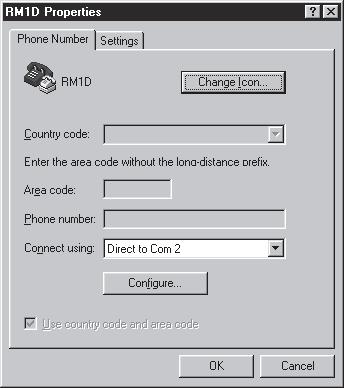
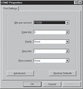
128 128 RM1d/RM1ds User Guide

129 Transferring the Software Once the download cable is connected between the PC and the RM1d and the PC configured as described, the following procedure needs to be completed to enable the new software to be downloaded. Make sure that the RM1d is switched off. Hold down the U key on your PC keyboard whilst switching the DPS-2 power supply on. The following message should appear in the window of Hyperterminal: Waiting for application code Upload Once the above message appears you can release the U key. Select, Transfer SendFile and click Browse... to locate and select the.abs file from wherever you put it (eg, c:\rm1d Software). Select the Xmodem protocol in the lower box. Click send. While the program is being transferred Hyper terminal should show a progress box. The transfer will take about 3 minutes 20 seconds. During the transfer the RM1D desk will be blank. This is OK. So long as the Packet number is changing on the PC the new software is being transferred OK. RM1d/RM1ds User Guide 129
Quick Start Guide. Soundcraft Si Series Quick Start Guide Issue 1010
 Quick Start Guide Soundcraft Si Series Quick Start Guide Issue 1010 Page 1 INTRODUCTION IMPORTANT Please read this manual carefully before using your mixer for the first time. Firstly, thanks for choosing
2
 328 328 USER GUIDE NB Before you go any further, please read this first page as it will tell you all you need to know about starting off with the Spirit Digital 328 From all of us to you Thank you for
S1 Digital/Analogue Radio Broadcast Mixer September 2009
 S1 Digital/Analogue Radio Broadcast Mixer September 2009 www.sonifex.co.uk t: +44 (0)1933 650 700 f: +44 (0)1933 650 726 sales@sonifex.co.uk S1 Radio Digital/Analogue Broadcast Mixer Radio Broadcast Mixer
S1 Digital/Analogue Radio Broadcast Mixer
 S1 Digital/Analogue Radio Broadcast Mixer September 2009 www.sonifex.co.uk t: +44 (0)1933 650 700 f: +44 (0)1933 650 726 sales@sonifex.co.uk S1 Radio Digital/Analogue Broadcast Mixer Radio Broadcast Mixer
T L Audio. User Manual C1 VALVE COMPRESSOR. Tony Larking Professional Sales Limited, Letchworth, England.
 T L Audio User Manual C1 VALVE COMPRESSOR Tony Larking Professional Sales Limited, Letchworth, England. Tel: 01462 490600. International +44 1462 490600. Fax: 01462 490700. International +44 1462 490700.
CAUTIONS Must be followed carefully to avoid bodily injury.
 SOFTWARE v 2 USER GUIDE ZM0219 - Issue 3 SAFETY GUIDE Safety Symbol Guide Approvals and Notice Warranty Important Safety Instructions Cautions Warnings II III IV V V VI i SAFETY SYMBOL GUIDE For your
SOUNDCRAFT. User Guide
 SOUNDCRAFT User Guide Harman International Industries Ltd. 1996,1997 All rights reserved Parts of the design of this product may be protected by worldwide patents. Part No. ZM0143 Issue 3 Soundcraft is
S0 Radio Broadcasting Mixer. June catalogue. Manufacturers of audio & video products for radio & TV broadcasters
 S0 Radio Broadcasting Mixer June 2012 catalogue Manufacturers of audio & video products for radio & TV broadcasters S0 Radio Broadcasting Mixer A simple radio mixer for novice and professional users The
USER MANUAL MX102 & MX1202
 USER MANUAL MX102 & MX1202 WWW.PULSE-AUDIO.CO.UK 1 SAVE THESE SAFETY INSTRUCTIONS Thank you for purchasing our product. To assure the optimum performance, please read this manual carefully and keep it
Q-TV2. User Manual. for Screens
 Q-TV2 User Manual for 30-42 Screens Contents Introduction 02 Safety Guidelines 03 Getting started 03 Potential Uses 04 Carton Contents 05 Q-TV2 Controls 05 Remote Fixings 06 Fixing Rails 07 Fitting Q-TV2
TS2.8 Sub OWNER S MANUAL
 TS2.8 Sub OWNER S MANUAL TS2.8 Sub CONTENTS IMPORTANT SAFETY INSTRUCTIONS 03 WARNINGS 03 FUSE PROTECTION 04 WARNING: STRONG MAGNETIC FIELD 04 EMC / EMI 04 ECODESIGN STANDBY POWER CONSUMPTION 04 WARRANTY
Utility Amplifier GA6A Model
 Utility Amplifier GA6A Model Installation and Use Manual 2004 Bogen Communications, Inc. All rights reserved. Specifications subject to change without notice. 54-5757-03D 1503 NOTICE: Every effort was
LX20 OPERATORS MANUAL
 LX20 OPERATORS MANUAL CONTENTS SAFETY CONSIDERATIONS page 1 INSTALLATION page 2 INTRODUCTION page 2 FIRST TIME USER page 3 SYSTEM OPERATING LEVELS page 3 FRONT & REAR PANEL LAYOUT page 4 OPERATION page
HD Digital Set-Top Box Quick Start Guide
 HD Digital Set-Top Box Quick Start Guide Eagle Communications HD Digital Set-Top Box Important Safety Instructions WARNING TO REDUCE THE RISK OF FIRE OR ELECTRIC SHOCK, DO NOT EXPOSE THIS PRODUCT TO RAIN
TL AUDIO M4 TUBE CONSOLE
 TL AUDIO M4 TUBE CONSOLE USER MANUAL TL AUDIO M4 TUBE CONSOLE M4 INTRODUCTION... 3 M4 MIXER TECHNICAL SPECIFICATION... 4 Mic Input:... 4 Line Input:... 4 Phase Rev:... 4 High Pass Filter:... 4 Frequency
Technical Specifications
 INSTALLATION SHEET AND OPERATORS MANUAL General Description: The is a mixer/preamplifier that includes 6 channels that each include a microphone input at screw terminals and an aux input at an RCA jack.
1812R Blues King 12. User Manual
 1812R Blues King 12 User Manual All contents c Absara Audio LLC 2018 1. Important Safety Information The triangle surrounding an exclamation mark alerts users to the presence of important warnings or information.
CMX-DSP Compact Mixers
 CMX-DSP Compact Mixers CMX4-DSP, CMX8-DSP, CMX12-DSP Introduction Thank you for choosing a Pulse CMX-DSP series mixer. This product has been designed to offer reliable, high quality mixing for stage and/or
CHAPTER 3 AUDIO MIXER DIGITAL AUDIO PRODUCTION [IP3038PA]
![CHAPTER 3 AUDIO MIXER DIGITAL AUDIO PRODUCTION [IP3038PA]](/thumbs/73/68858919.jpg "CHAPTER 3 AUDIO MIXER DIGITAL AUDIO PRODUCTION [IP3038PA]") CHAPTER 3 AUDIO MIXER DIGITAL AUDIO PRODUCTION [IP3038PA] Learning Objectives By the end of this chapter, students should be able to: 1 State the function of the audio mixer in the sound studio. 2 Explain
CHAPTER 3 AUDIO MIXER DIGITAL AUDIO PRODUCTION [IP3038PA] Learning Objectives By the end of this chapter, students should be able to: 1 State the function of the audio mixer in the sound studio. 2 Explain
Evolution Digital HD Set-Top Box Important Safety Instructions
 Evolution Digital HD Set-Top Box Important Safety Instructions 1. Read these instructions. 2. Keep these instructions. 3. Heed all warnings. 4. Follow all instructions. 5. Do not use this apparatus near
MON8-1/SDI 1U 8-Channel SDI Digital Multi-Display Video Monitor
 MON8-1/SDI 1U 8-Channel SDI Digital Multi-Display Video Monitor (Document P/N 821626, Rev-A) with Eight Backlit 1.8" LCD Displays, Eight SDI Video Inputs, Eight SDI Re-Clocked Outputs, and Eight CVBS (Analog)
GIULIA Y. combo amplifier for acoustic instruments
 GIULIA Y combo amplifier for acoustic instruments IMPORTANT SAFETY INSTRUCTIONS THE LIGHTNING FLASH WITH ARROWHEAD SYMBOL, WITHIN AN EQUILATERAL TRIANGLE, IS INTENDED TO ALERT THE USER TO THE PRESENCE
AxumVideo 0 intro. Now that you have connected the different AXUM system parts, you are ready to configure the system according to your own needs.
 AxumVideo 0 intro Now that you have connected the different AXUM system parts, you are ready to configure the system according to your own needs. On the left we see the RACK unit and on the right we see
Recording to Tape (Analogue or Digital)...10
...10") c o n t e n t s DUAL MIC-PRE Green Dual Mic Pre (introduction).............................4 Section (i): Setting Up Power Connections...........................................4 Power Supply................................................5
c o n t e n t s DUAL MIC-PRE Green Dual Mic Pre (introduction).............................4 Section (i): Setting Up Power Connections...........................................4 Power Supply................................................5
CM4-BT. Compact Mixer with Bluetooth UK User Manual
 CM4-BT Compact Mixer with Bluetooth 170.804UK User Manual Caution: Please read this manual carefully before operating Damage caused by misuse is not covered by the warranty Introduction: Thank you for
SOUNDCRAFT USER GUIDE
 SOUNDCRAFT USER GUIDE Soundcraft Electronics 1995 All rights reserved Parts of the design of this product may be protected by worldwide patents. Part No. ZM0078-03 Information in this manual is subject
Chapter 4 Signal Paths
 Chapter 4 Signal Paths The OXF-R3 system can be used to build a wide variety of signal paths with maximum flexibility from a basic default configuration. Creating configurations is simple. Signal paths
USER MANUAL PMX1204 & PMX1604
 USER MANUAL PMX1204 & PMX1604 WWW.PULSE-AUDIO.CO.UK 1 SAVE THESE SAFETY INSTRUCTIONS Thank you for purchasing our product. To assure the optimum performance, please read this manual carefully and keep
Overview. A 16 channel frame is shown.
 Overview A 16 channel frame is shown. 22 Mono Input Channel 1 - MIC INPUT The mic input accepts XLR-type connectors and is designed to suit a wide range of BALANCED or UNBALANCED signals. Professional
Element 78 MPE-200. by Summit Audio. Guide To Operations. for software version 1.23
 Element 78 MPE-200 by Summit Audio Guide To Operations for software version 1.23 TABLE OF CONTENTS IMPORTANT SAFETY AND GROUNDING INSTRUCTIONS COVER 1. UNPACKING AND CONNECTING...3 AUDIO CONNECTIONS...4
AEQ BRAVO Broadcast Mixing Console
 AEQ Broadcast Mixing Console USER S MANUAL ED. 12/07 V. 1.5-20/05/2008 CONTENTS 1. INTRODUCTION... 3 1.1. General... 3 1.2. Maintenance... 3 1.3. Warranty... 4 2. EQUIPMENT POWER SUPPLY... 5 2.1. General...
CAUTION RISK OF ELECTRIC SHOCK NO NOT OPEN
 Evolution Digital HD Set-Top Box Important Safety Instructions 1. Read these instructions. 2. Keep these instructions. 3. Heed all warnings. 4. Follow all instructions. 5. Do not use this apparatus near
HD Digital MPEG2 Encoder / QAM Modulator
 HD Digital MPEG2 Encoder / QAM Modulator YPrPb VGA In QAM Out series Get Going Guide ZvPro 600 Series is a one or two-channel Component or VGA-to-QAM MPEG 2 Encoder/ Modulator, all in a compact package
TASCAM DM-24. The DM-24 Basics. TEAC Professional Division. Digital Mixing console
 TASCAM TEAC Professional Division DM-24 Digital Mixing console The DM-24 Basics DM-24 SIGNAL FLOW... 3 INPUTS... 3 RETURNS... 3 OPTIONS... 4 OUTPUTS... 5 AUX SENDS... 5 TRACKING OPTIONS... 5 Using AUX
HD Digital MPEG2 Encoder / QAM Modulator
 HD Digital MPEG2 Encoder / QAM Modulator HDMI In QAM Out series Get Going Guide ZvPro 800 Series is a one or two-channel unencrypted HDMI-to-QAM MPEG 2 Encoder / QAM Modulator, all in a compact package
User Manual. Neve Channel Strip Issue 2. !!!Please read includes important safety instructions!!!
 User Manual Neve 8801 Channel Strip 527 358 Issue 2!!!Please read includes important safety instructions!!! 2007 AMS Neve Ltd own the copyright of all information and drawings contained in this manual
2.0 Wall Mount TV Soundbar Instruction Manual
 8010275 2.0 Wall Mount TV Soundbar Instruction Manual Read all of the instructions before using this soundbar and keep the manual in a safe place for future reference. Safety Information CA UT IO N RISK
Reveal 402 / 502 / 802. English Manual
 Reveal 402 / 502 / 802 English Manual English manual English manual Important safety instructions 1. Read these instructions. 2. Keep these instructions. 3. Heed all warnings. 4. Follow all instructions.
AEQ BRAVO Broadcast Mixing Console
 AEQ Broadcast Mixing Console USER S MANUAL ED 12/07 V 11-17/12/2007 CONTENTS 1 INTRODUCTION 3 11 General 3 12 Maintenance 3 13 Warranty 4 2 EQUIPMENT POWER SUPPLY 5 21 General 5 22 Switching on the equipment
USER GUIDE MULTI-CHANNEL STEREO MIXER S MIX 4M2S UD
 USER GUIDE MULTI-CHANNEL STEREO MIXER S MIX 4M2S UD FEATURES 4 mono input channels and 2 stereo input channels. Frequency EQ on each input channel. Low-noise mic pre-amp on microphone inputs. Low cut filter
Introduction SAFETY PRECAUTIONS. Contents
 0 0 0 0 9 8 7 6 0 0 9 8 7 6 0 0 9 8 7 6 0 Contents Introduction Safety Precautions Connections System Overview Controls in Detail Inputs Master 7 Advanced Features 8 Initial Setting Up 9 Applications 0
Downloaded from manuals search engine
 M-SERIES USER GUIDE SAFETY GUIDE Page Safety Symbol Guide 2 Approvals and Notice 3 Warranty 4 Important Safety Instructions 5 Cautions 5 Warnings 6 1 USER GUIDE SAFETY SYMBOL GUIDE For your own safety
SwiftMix Automation Safety
 Operations Manual SwiftMix TM Automation Thank you for your purchase of the SwiftMix automation for the 5088 console. Everyone at Rupert Neve Designs hopes you enjoy using this tool as much as we have
MON8-1 1U 8-Channel Multi-Display Video Monitor
 MON8-1 1U 8-Channel Multi-Display Video Monitor with Eight Backlit 1.75" LCD Displays, Eight CVBS Video Inputs, and Eight Loop-through Outputs Document P/N 821568 Rev-A User Manual CONTENTS Title and Contents...
Please read this manual carefully before using your mixer for the first time.
 Quick Start Guide IMPORTANT Please read this manual carefully before using your mixer for the first time. This equipment complies with the EMC directive 2004/108/EC and LVD 2006/95/EC This product is approved
CLOCKAUDIO. MR88 Automatic Microphone Mixer. Version 4.2
 CLOCKAUDIO MR88 Automatic Microphone Mixer Version 4.2 Clockaudio Limited,22 Arnside Road WATERLOOVILLE Hampshire. UK Tel : +44 (0)2392 251193 Fax : +44 (0)2392 251201 Email : sales@clockaudio.co.uk CONTENTS
ANALOG RADIO MIXER. Flexible. Affordable. Built To Last.
 ANALOG RADIO MIXER Flexible. Affordable. Built To Last. Audioarts AIR-4 A N A L O G R A D I O M I X E R At Audioarts, value engineering is straightforward: Define the features our customers require. Design
CDM10: Channel USB Mixer. Item ref: UK User Manual
 CDM10:4 19 4 Channel USB Mixer Item ref: 171.135UK User Manual Caution: Please read this manual carefully before operating Damage caused by misuse is not covered by the warranty Introduction Thank you
Check our knowledge base at
 USER MANUAL Check our knowledge base at www.paralinx.net/support Copyright 2015 Paralinx LLC All Rights Reserved TABLE OF CONTENTS 1 Important Notice 10 LCD Screen 2 Safety Instructions 11 Indicators 3
FF DUAL FORMAT DJ MIXER USERS MANUAL
 FF - 4000 DUAL FORMAT DJ MIXER USERS MANUAL FF - 4000 INTRODUCTION The features and layout of the FF-4000 were determined in collaboration with leading loudspeaker manufacturers Funktion One, who canvassed
Personal Q Guide for VENUE Systems
 Personal Q Guide for VENUE Systems Version 1.0 Digidesign 2001 Junipero Serra Boulevard Daly City, CA 940-3886 USA tel: 650 731 6300 fax: 650 731 6399 Technical Support (USA) tel: 650 731 6100 fax: 650
DisplayPort Extender over 2 LC Fibers
 DisplayPort Extender over 2 LC Fibers Audio 3GSDI Embedder EXT-DP-CP-2FO User Manual Release A2 DisplayPort Extender over 2 LC Fibers Important Safety Instructions 1. Read these instructions. 2. Keep these
1608-II and 2448 Recording Console Operator s Manual
 Recording Console Operator s Manual Written for Automated Processes ncorporated by Dan Pfeifer Rev. 18-12-30 2018 8301 Patuxent Range Road Jessup, MD 20794 USA 301-776-7879 http://www.apiaudio.com Table
M A S T E R S E C T I O N. User Manual
 M A S T E R S E C T I O N User Manual Version 1.02: July 2007 Contents. Safety Information.... 3 Welcome.... 4 Connections.... 5 A Basic Set-up 5 Setting Up.... 7 Adjusting Input Levels 7 Taking Account
SERIES 10 USER GUIDE
 SERIES 10 USER GUIDE Soundcraft Electronics Ltd. 1992, 1993 All rights reserved Parts of the design of this product may be protected by worldwide patents. Issue 2 Part No. ZM0004 Information in this manual
MANUAL ENGLISH Core Club Ordercode: D2314
 MANUAL ENGLISH Core Club Ordercode: Highlite International B.V. Vestastraat 2 6468 EX Kerkrade the Netherlands Table of contents Warning... 2 Unpacking Instructions... 2 Safety Instructions... 2 Operating
Disclaimer. Trademarks. Copyright. Contact Us Control4 Corporation S. Election Road Salt Lake City, UT USA
 Disclaimer Trademarks Copyright Control4 makes no representations or warranties with respect to this publication, and specifically disclaims any express or implied warranties of merchantability or fitness
Introducing the New Daking Console
 Introducing the New Daking Console Daking The Console that can change from a Legacy Bussing scheme to DAW Direct Routing with the touch of a button. Features: Class A Circuitry Transformer Coupled Pre-Amps
USER GUIDE 8-CHANNEL DMX CONTROLLER December 2013 Version 1.0 CHASE / STROBE SPEED FADE SPEED RED GREEN BLUE WHITE AMBER DIMMER INSERT
 8-CHANNEL DMX CONTROLLER RED GREEN BLUE YELLOW 1 2 3 4 5 6 CYAN ORANGE PURPLE WHITE RED GREEN BLUE WHITE AMBER DIMMER RECORD INSERT DELETE TAP CLEAR MANUAL MUSIC 1 2 3 5 6 7 AUTO CHASE / STROBE SPEED 4
FD Trinitron Colour Television
 R 4-205-569-32(1) FD Trinitron Television Instruction Manual GB KV-14LM1U 2000 by Sony Corporation NOTICE FOR CUSTOMERS IN THE UNITED KINGDOM A moulded plug complying with BS1363 is fitted to this equipment
Harman International Industries Limited Cranborne House Cranborne Road POTTERS BAR Hertfordshire EN6 3JN UK
 USER GUIDE 1 IMPORTANT Please read this manual carefully before using your mixer for the first time. Harman International Industries Ltd. 2006 All rights reserved Parts of the design of this product may
SAFETY PRECAUTIONS. The SPIRIT FX16 mixer must only be connected through the Power Supply supplied:
 INTRODUCTION Thank you for purchasing an FX16 mixer, brought to you with pride by the SPIRIT team of Andy, Colin, Chris, Simon, Mukesh, Graham, Martin, Paul, Tony and Peter, with the support of many others
PH-1. Italian MM & MC Phono Preamplifier OWNER S MANUAL
 PH-1 Italian MM & MC Phono Preamplifier OWNER S MANUAL IMPORTANT SAFETY INFORMATION CAUTION: TO REDUCE THE RISK OF ELECTRIC SHOCK, DO NOT REMOVE COVER (OR BACK). NO USER-SERVICEABLE PARTS INSIDE. REFER
C Class Signal Processors
 -5-3 -2-7 -1 0-10 -20 +4 VU SAMSON OPTICAL COMPRESSOR A U D I O C Class Signal Processors Safety Instructions Caution: To reduce the hazard of electrical shock, do not remove cover or back. No user serviceable
M-16DX 16-Channel Digital Mixer
 M-6DX 6-Channel Digital Mixer Workshop Getting Started with the M-6DX 007 Roland Corporation U.S. All rights reserved. No part of this publication may be reproduced in any form without the written permission
CL1200 MIXING CONSOLE. Item ref: UK User Manual
 CL1200 MIXING CONSOLE Item ref: 170.881UK User Manual Caution: Please read this manual carefully before operating Damage caused by misuse is not covered by the warranty Introduction Thank you for choosing
ART48 - MICIN/MIC-ULN. arthur ACOUSTIC FIDELITY USER MANUAL. Assembling instruction on ART48-L/Rmast manual
 V2 ACOUSTIC FIDELITY arthur ART48 - MICIN/MIC-ULN USER MANUAL Assembling instruction on ART48-L/Rmast manual WARNINGS PRECAUTIONS WARNINGS Read carefully this manual and follow these precautions before
HeadAmp 4 Pro. User s Manual. Project Series. Five Channel Headphone Amp with Listen and Talkback
 HeadAmp 4 Pro Five Channel Headphone Amp with Listen and Talkback Project Series User s Manual IMPORTANT SAFETY INSTRUCTIONS READ FIRST This symbol, wherever it appears, alerts you to the presence of
KD-CSW2x1. Operating Instructions. 2 Inputs to 1 Output Component Video/Audio Switcher. KD-CSW2x1 Operating Instructions.
 KD-CSW2x1 2 Inputs to 1 Output Video/ Switcher Operating Instructions Key Digital, led by digital video pioneer Mike Tsinberg, develops and manufactures high quality, cutting-edge technology solutions
PROFESSIONAL 2 CHANNEL SOLID-STATE MIC / LINE PREAMPLIFIER USER S MANUAL
 PROFESSIONAL 2 CHANNEL SOLID-STATE MIC / LINE PREAMPLIFIER USER S MANUAL SAFETY INSTRUCTIONS This symbol, wherever it appears, alerts you to important operating and maintenance instructions in the accompanying
User s manual. Sirus Pro MXA 6000
 User s manual Sirus Pro MXA 6000 Table of content 1. Safety instructions... 3 2. Control Elements... 5 2.1. Microphone channels... 5 2.2. Microphone channel... 6 2.3. Monitor Section... 6 2.4. Master Section...
BP2-MM MM Phono Preamplifier Owner s Manual
 BP2-MM MM Phono Preamplifier Owner s Manual Important Safety Instructions The lightning flash with arrowhead symbol within an equilateral triangle, is intended to alert the user to the presence of un-insulated
GB2 User Guide. GB2 User Guide
 GB2 User Guide GB2 User Guide 1 IMPORTANT Please read this manual carefully before using your mixer for the first time. Harman International Industries Ltd. 2006 All rights reserved Parts of the design
DisplayPort Extender over 2 LC Fibers
 DisplayPort Extender over 2 LC Fibers Audio 3GSDI Embedder EXT-DP-CP-2FO User Manual Release A2 DisplayPort Extender over 2 LC Fibers Important Safety Instructions 1. Read these instructions. 2. Keep these
AT-MX351a SmartMixer. Automatic Mixer. Installation and Operation. Output Level Gain 1 Gain 2 Gain 3 Gain 4 Aux In Master Monitor. Priority Pre-select
 AT-MX351a SmartMixer Automatic Mixer AUTOMATIC MIXER AT-MX351a Output Level Gain 1 Gain 2 Gain 3 Gain 4 Aux In Master Monitor -20-10 -6-3 0 +3 +6 Priority Pre-select Power Selected Channel 1 2 3 4 MANUAL
Oxygen ORDERCODE D2150
 Oxygen ORDERCODE D2150 Congratulations! You have bought a great, innovative product from DAP Audio. The DAP Audio Oxygen brings excitement to any venue. Whether you want simple plug-&-play action or a
SIGNAL PROCESSOR. Operation Manual
 SIGNAL PROCESSOR Operation Manual Using the PDF manual From the Contents on page 2, click on the desired topic to automatically jump to the corresponding page. Click on a link in this manual to jump to
SIGNAL PROCESSOR. Operation Manual
 SIGNAL PROCESSOR Operation Manual Using the PDF manual From the Contents on page 2, click on the desired topic to automatically jump to the corresponding page. Click on a link in this manual to jump to
CXM Mixer Installation & User Guide
 CXM Mixer Installation & User Guide Cloud Electronics Limited 140 Staniforth Road, Sheffield, S9 3HF England Tel +44 (0)114 244 7051 Fax +44 (0)114 242 5462 e-mail info@cloud.co.uk web site http://www.cloud.co.uk
DM-1CH SD DVB-T MODULATOR INSTRUCTION MANUAL
 DM-1CH SD DVB-T MODULATOR INSTRUCTION MANUAL 2. Caution Statements and Table of Contents Table of Contents 2. Caution Statements and Table of contents 3. Important Safety Instructions 4. Important Safety
28 4K LED monitor. User Manual M284K
 28 4K LED monitor User Manual M284K CONTENTS Safety Information... 2 What s included..... 4 Getting Started....... 8 Troubleshooting.... 14 Specification.... 15 2 of 15 SAFETY INFORMATION Read these instructions
TF5 / TF3 / TF1 DIGITAL MIXING CONSOLE. TF StageMix User's Guide
 TF5 / TF3 / TF1 DIGITAL MIXING CONSOLE EN Note The software and this document are the exclusive copyrights of Yamaha Corporation. Copying or modifying the software or reproduction of this document, by
42 input, 8-Bus Digital Console with Lexicon effects
 42 input, 8-Bus Digital Console with Lexicon effects Up to 42 Inputs at Mixdown 8 Bus 16 Mic/Line & 5 Stereo Inputs 16 Digital Tape Returns on ADAT Optical and TDIF formats All Inputs have access to 3-Band
20.12 mixer. user manual
 20.12 mixer user manual Musikhaus Thomann Thomann GmbH Hans-Thomann-Straße 1 96138 Burgebrach Germany Telephone: +49 (0) 9546 9223-0 E-mail: info@thomann.de Internet: www.thomann.de 07.09.2018, ID: 433540
Digital Magic OPERATING INSTRUCTIONS. Video Processor, STB, and 12 Channel DA. Model KD-DH12
 Digital Magic Video Processor, STB, and 12 Channel DA Digital Magic is an all-in-one ATSC Set Top Box, Scaler to convert the video program to match your display s native resolution, and 12-channel Component/Composite
DIGITAL SPEAKER MANAGEMENT UK
 DSM2-6mkII DIGITAL SPEAKER MANAGEMENT 170.659UK Features 96kHz sampling frequency, 32-bit A/D and D/A converter, 24-bit DSP processor Input channel: 6-band parametric EQ, Delay, Polarity Output channel:
HD Digital MPEG2 Encoder / QAM Modulator Get Going Guide
 series HD Digital MPEG2 Encoder / QAM Modulator Get Going Guide HDb2640 HDb2620 HDb2540 HDb2520 The HDbridge 2000 Series is a combination HD MPEG 2 Encoder and frequency-agile QAM Modulator, all in a 1RU
BEYOND 324 LIVE INPUT LIVE SOUND DIGITAL MIXING CONSOLE
 BEYOND 324 LIVE... DIGITAL 328 LX7 32 Channel Digital Mixing Console LIVE 4 2 12 to 40 Channel 4 Group Live Mixing 24 to 40 Input Live Mixing LIVE 3 2 8 to 24 Channel 3-Buss Live Mixing Spirit 324 Live
TUBE MIX FIVE CHANNEL MIXER WITH USB AND ASSIGNABLE 12AX7 TUBE. User's Manual
 TUBE MIX FIVE CHANNEL MIXER WITH USB AND ASSIGNABLE 12AX7 TUBE User's Manual IMPORTANT SAFETY INSTRUCTIONS READ FIRST This symbol, wherever it appears, alerts you to the presence of uninsulated dangerous
SAFETY GUIDE. Page Safety Symbol Guide 2 Approvals and Notice 3 ranty 4 5 Cautions 5 arnings
 SAFETY GUIDE Page Safety Symbol Guide 2 Approvals and Notice 3 War arranty ranty 4 Important Safety Instructions 5 Cautions 5 War arnings 6 1 USER GUIDE Safety Symbol Guide For your own safety and to avoid
MIDAS Venice Pin-Assignments Page 1 / 3 Mono-Channel-PCB Stereo- / Master - PCB CN 1 circuit diagram number CN 6 circuit diagram number CN
 MIDAS Venice Pin-Assignments Page 1 / 3 Mono-Channel-PCB 81346 Stereo- / Master - PCB 82230 CN 1 circuit diagram number CN 6 circuit diagram number CN 7 circuit diagram number CN 1 circuit diagram number
Natural-sounding telephone audio... Hybrids
 Natural-sounding telephone audio... Hybrids ... for broadcast, conferencing and public address About Comrex DH Series Digital Telephone Hybrids When you want to present, broadcast, or record a telephone
Solid State Logic S O U N D V I S I O N
 Solid State Logic S O U N D V I S I O N SUPERANALOGUE X - R A C K Super-Analogue Outboard XR622 X-Rack Master Module User s Guide This documentation package contains the User s Guide for your new X-Rack
HDMI 5x1 Switch B-240-HDSWTCH-5X1 INSTALLATION MANUAL
 HDMI 5x1 Switch B-240-HDSWTCH-5X1 INSTALLATION MANUAL IMPORTANT SAFETY INSTRUCTIONS To reduce the risk of fire or electric shock, read and follow all instructions and warnings in this manual. Keep this
ZVOX AccuVoice TV Speaker MODEL AV150.
 ZVOX AccuVoice TV Speaker MODEL AV150 www.zvoxaudio.com READ THIS FIRST Important Safety Instructions For ZVOX Audio System WARNING TO PREVENT FIRE OR SHOCK HAZARD, DO NOT EXPOSE THIS APPLIANCE TO RAIN
*Prefer. 600 MHz 4K ULTRA. 60Hz, 4:4:4. over one SC-Terminated Fiber-Optic Cable EXT-DP-4K600-1SC. User Manual. Release A1
 *Prefer 600 MHz 4K ULTRA 60Hz, 4:4:4 DisplayPort 1.2 Extender over one SC-Terminated Fiber-Optic Cable EXT-DP-4K600-1SC User Manual Release A1 Important Safety Instructions 1. Read these instructions.
Model 1606 Super. User Manual
 Model 1606 Super User Manual All contents c Absara Audio LLC 2014 1. Important Safety Information The triangle surrounding an exclamation mark alerts users to the presence of important warnings or information.
Soundcraft USA, 8500 Balboa Boulevard, Northridge, CA 91329, USA T: F: E:
 Soundcraft, Harman International Industries Ltd., Cranborne House, Cranborne Road, Potters Bar, Hertfordshire EN6 3JN, UK T: +44 (0)1707 665000 F: +44 (0)1707 660742 E: soundcraft.marketing@harman.com
SOUNDCRAFT USER GUIDE
 SOUNDCRAFT USER GUIDE Soundcraft Electronics Ltd. All rights reserved Parts of the design of this product may be protected by worldwide patents. Part No. ZM- Information in this manual is subject to change
KD-CTCA3. Component Video to VGA Adapter
 KD-CTCA3 Component Video to VGA Adapter Model KD-CTCA3 KD-CTCA3 Component Video to VGA Adapter Model KD-CTCA3 Component Video (YPrPb) input to VGA Video (RGBHV) output Video Adapter with added features