ANDIAMO 2.DA. Hardware Guide. Version 2.0
|
|
|
- Karen Harrell
- 6 years ago
- Views:
Transcription


1 ANDIAMO 2.DA Hardware Guide Version 2.0
2 Copyright All rights reserved. Permission to reprint or electronically reproduce any document or graphic in whole or in part for any reason is expressly prohibited, unless prior written consent is obtained from the DirectOut GmbH. All trademarks and registered trademarks belong to their respective owners. It cannot be guaranteed that all product names, products, trademarks, requisitions, regulations, guidelines, specifications and norms are free from trade mark rights of third parties. All entries in this document have been thoroughly checked; however no guarantee for correctness can be given. DirectOut GmbH cannot be held responsible for any misleading or incorrect information provided throughout this manual. DirectOut GmbH reserves the right to change specifications at any time without notice. DirectOut Technologies is a registered trademark of the DirectOut GmbH. DirectOut GmbH, 2017 page 2 of 48 ANDIAMO 2.DA Hardware Guide - Version 2.0
3 Table of contents About This Manual 5 How to Use This Manual... 5 Conventions... 5 CHAPTER 1: Overview 6 Introduction... 6 Feature Summary... 7 Applications... 7 CHAPTER 2: Legal issues & facts 8 Before Installing This Device... 8 Defective Parts/Modules... 8 First Aid (in case of electric shock)... 9 Updates Conditions of Warranty Intended Operation Conformity & Certificates Contact Contents Accessories CHAPTER 3: Installation 15 Installing the Device CHAPTER 4: Operation 20 Introduction Global Control Menu Control Clocking Sample Rates Output Format Level Settings Level Meters Signal Routing Connecting MADI Connecting Word clock...34 Connecting USB...34 Connecting Analog CHAPTER 5: Menu Navigation 36 CHAPTER 6: Troubleshooting and Maintenance 39 Troubleshooting Maintenance ANDIAMO 2.DA Hardware Guide - Version 2.0 page 3 of 48
4 CHAPTER 7: Technical Data 40 Appendix A - DSUB-25 Pin assignment 42 Index 43 page 4 of 48 ANDIAMO 2.DA Hardware Guide - Version 2.0
5 About This Manual About This Manual How to Use This Manual This manual guides you through the installation and operation of the device. Use the Table of Contents at the beginning of the manual or Index Directory at the end of the document to locate help on a particular topic. You can access more information and latest news by visiting on the DirectOut website at Conventions The following symbols are used to draw your attention to: TIPS! indicate useful hints and shortcuts. NOTES! are used for important points of clarification or cross references. WARNINGS! alert you when an action should always be observed. This document relates to: ANDIAMO 2.DA - firmware version 1.5 ANDIAMO 2.DA Hardware Guide - Version 2.0 page 5 of 48
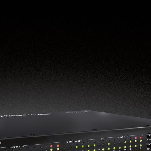
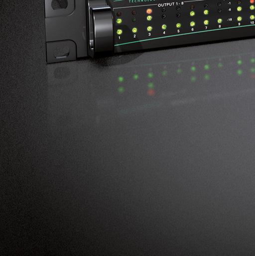
6 CHAPTER 1: Overview CHAPTER 1: Overview Introduction The ANDIAMO 2.DA is a high quality DA converter for MADI signals. It provides two MADI inputs and outputs and 32 channels analog outputs. With one RU height, two redundant power supplies and excellent sounding converters the device offers best and reliable audio quality at a minimal need of rackspace. page 6 of 48 ANDIAMO 2.DA Hardware Guide - Version 2.0
7 CHAPTER 1: Overview Feature Summary MADI Ports 2 x SC-Socket multi/single-mode (SC/SC) or 1 x SC-Socket multi/single-mode & 1 x coaxial BNC connector, 75 Ω (BNC/SC) MADI Formats 56/64 channel, 48k/96k Frame, S/MUX 2/4 Sample Rates 44.1, 48, 88.2, 96, 176.4, 192 khz ±12.5% Analog Outputs Clock Inputs Clock Outputs USB Port Routing Matrix Remote Control Power Supply 32 x channels analog output, balanced via DSUB-25, AES59 compliant 1 x Word clock, coaxial BNC, 75 Ω termination switchable, This input also accepts an AES3 frame (AES11). 1 x Word clock, coaxial BNC USB 2.0 port for firmware updates and remote control Signal routing on a per channel basis 128 x 160 routing matrix. Software Remote control via USB, Serial over MADI, MIDI over MADI or DO.Net This device is equipped with two wide range power supplies (84 V to 264 V AC / 47 Hz to 63 Hz / safety class 1) Applications ANDIAMO 2.DA can be used for conversion, monitoring and routing of analog and digital signals. Typical applications include: monitoring digital audio signal routing / distribution (128 x 160 cross points) format conversion of MADI signals... ANDIAMO 2.DA Hardware Guide - Version 2.0 page 7 of 48
8 CHAPTER 2: Legal issues & facts CHAPTER 2: Legal issues & facts Before Installing This Device WARNING! Please read and observe all of the following notes before installing this product: Check the hardware device for transport damage. Any devices showing signs of mechanical damage or damage from the spillage of liquids must not be connected to the mains supply, or disconnected from the mains immediately by pulling out the power lead. All devices must be grounded. The device is grounded through its IEC power connections. All devices must be connected to the mains using the three-cord power leads supplied with the system. Only supply electrical interfaces with the voltages and signals described in these instructions. Do not use the device at extreme temperatures. Proper operation can only be guaranteed between temperatures of 5º C and 45º C and a maximum relative humidity of 80 %, non-condensing. The cabinet of the device will heat up. Do not place the device close to heating sources (e.g. heaters). Observe the environmental conditions. Defective Parts/Modules WARNING! This device contains no user-serviceable parts. Therefore do not open the device. In the event of a hardware defect, please send the device to your DirectOut representative together with a detailed description of the fault. We would like to remind you to please check carefully whether the failure is caused by erroneous configuration, operation or connection before sending parts for repair. page 8 of 48 ANDIAMO 2.DA Hardware Guide - Version 2.0
9 CHAPTER 2: Legal issues & facts First Aid (in case of electric shock) WARNING! Do not touch the person or his/her clothing before power is turned off, otherwise you risk sustaining an electric shock yourself. Separate the person as quickly as possible from the electric power source as follows: -- Switch off the equipment. -- Unplug or disconnect the mains cable. Move the person away from the power source by using dry insulating material (such as wood or plastic). If the person is unconscious: -- Check their pulse and reanimate if their respiration is poor. -- Lay the body down and turn it to one side. Call for a doctor immediately. Having sustained an electric shock, always consult a doctor. ANDIAMO 2.DA Hardware Guide - Version 2.0 page 9 of 48
10 CHAPTER 2: Legal issues & facts Updates DirectOut products are continually in development, and therefore the information in this manual may be superseded by new releases. To access the latest documentation, please visit the DirectOut website: This guide refers to firmware version 1.5. Intended Operation ANDIAMO 2.DA is designed for conversion of audio signals from digital to analog. In this context digital audio refers to a MADI signal (AES10). WARNING! No compensation can be claimed for damages caused by operation of this unit other than for the intended use described above. Consecutive damages are also excluded explicitly. The general terms and conditions of business of DirectOut GmbH are applied. Conditions of Warranty This unit has been designed and examined carefully by the manufacturer and complies with actual norms and directives. Warranty is granted by DirectOut GmbH over the period of two years for all components that are essential for proper and intended operation of the device. The date of purchase is applied for this period. Consumable parts (e.g. battery) are excluded from warranty claims. WARNING! All claims of warranty will expire once the device has been opened or modified, or if instructions and warnings were ignored. For warranty claims please contact the dealer where your device was acquired. page 10 of 48 ANDIAMO 2.DA Hardware Guide - Version 2.0
11 CHAPTER 2: Legal issues & facts Conformity & Certificates CE This device complies with the basic requests of applicable EU guidelines. The appropriate procedure for approval has been carried out. RoHS (Restriction of the use of certain Hazardous Substances) This device was constructed fulfilling the directive on the restriction of the use of certain hazardous substances in electrical and electronic equipment 2002/95/EC. WEEE (Directive on Waste Electrical and Electronic Equipment) Due to the directive 2002/96/EC for waste disposal this device must be recycled. For correct recycling please dispatch the device to: DirectOut GmbH, Leipziger Str Mittweida Germany Only stamped parcels will be accepted! WEEE-Reg.-No. DE Contact DirectOut GmbH Leipziger Str. 32, Mittweida, Germany Phone: +49 (0) Fax: +49 (0) Mail: ANDIAMO 2.DA Hardware Guide - Version 2.0 page 11 of 48
 2 x power chord 2 x fixing unit for power plug 1 x Hardware Guide To complete the delivery please download from the product page on the DirectOut website (www.directout.")
.")
12 CHAPTER 2: Legal issues & facts Contents The contents of your ANDIAMO 2.DA package should include: 1 x ANDIAMO 2.DA (19, 1 RU) 2 x power chord 2 x fixing unit for power plug 1 x Hardware Guide To complete the delivery please download from the product page on the DirectOut website ( USB Serial driver latest firmware Software Guide ANDIAMO Remote ANDIAMO Remote application Two different MADI I/O configurations are available: 1 x SC-Socket 2 x SC-Socket 1 x BNC coaxial Three different versions with different analog reference levels are available: + 6 / + 15 dbu + 9 / + 18 dbu + 15 / + 24 dbu The version is marked on the rear panel (I/O level). NOTE Check the I/O configuration (MADI Ports and analog reference level) of your device before proceeding with the installation. Single-Mode / Multi-Mode The SC ports are multi-mode as default. It is possible to equip the device with single-mode SC ports. The housing of single-mode ports is colored blue. multi-mode single-mode page 12 of 48 ANDIAMO 2.DA Hardware Guide - Version 2.0
13 CHAPTER 2: Legal issues & facts Accessories BREAKOUT The BREAKOUT series is a range of adaptor boxes available in different variants to extend the coverage of the ANDIAMO series. They are equipped with XLR or BNC connectors on the front panel and DSUB-25 connectors on the rear panel. Audio signals are carried passively between the front and rear panels. The small form factor and angle brackets also allow for mounting the devices on the back of an ANDIAMO unit. BREAKOUT.AN8 - analog input / output, 8 channels Article code: DOBOB0719 BREAKOUT.AN16I - analog input, 16 channels Article code: DOBOB0720 BREAKOUT.AN16O - analog output, 16 channels Article code: DOBOB0721 ANDIAMO 2.DA Hardware Guide - Version 2.0 page 13 of 48
14 CHAPTER 2: Legal issues & facts BREAKOUT.AES - digital input / output, 8 AES3 ports (16 channels) Article Code: DOBOB0718 BREAKOUT.AESID - digital input / output, 16 AESid ports (32 channels) Article Code: DOBOB0722 Patch Chords Cabling from Cordial provides appropriate connection of the BREAKOUT with your ANDIAMO device to ensure proper transmission of the audio signals. Name Description Article code DSUB25.AN50 DSUB25.AN100 DSUB25.AES50 DSUB25.AES100 Analog patch cable for connection with BREAKOUT.AN16I, AN16O, AN8, transferring 8 audio channels, length 0.5 m Analog patch cable for connection with BREAKOUT.AN16I, AN16O, AN8, transferring 8 audio channels, length 1.0 m Digital patch cable for connection with BREAKOUT.AES or AESid transferring 8 audio channels, length 0.5 m Digital patch cable for connection with BREAKOUT.AES or AESid transferring 8 audio channels, length 0.5 m DOCAA0334 DOCAA0335 DOCAA0332 DOCAA0333 page 14 of 48 ANDIAMO 2.DA Hardware Guide - Version 2.0

15 CHAPTER 3: Installation CHAPTER 3: Installation Installing the Device 1. Open the packaging and check that the contents have been delivered complete and undamaged. 2. Fix the device in a 19 frame with four screws, or place it on a non-slip horizontal surface. WARNING! Avoid damage from condensation by waiting for the device to adapt to the environmental temperature. Proper operation can only be guaranteed between temperatures of 5º C and 45º C and a maximum relative humidity of 80%, noncondensing. Ensure that the unit has sufficient air circulation for cooling. Do not cover the fan outlets and the slots at the sides of the device! Do not block the fans by putting objects through the protective grid! AIR AIR 3. Remove the protective cap from the optical MADI port(s) before use. BNC / SC Version SC / SC Version NOTE Retain the protective cap if the optical port is unused. This will protect against soiling which can lead to malfunction. ANDIAMO 2.DA Hardware Guide - Version 2.0 page 15 of 48

16 CHAPTER 3: Installation 4. Connect the signal cables for the analog audio signals to the DSUB-25 connectors. WARNING Do not connect voltage sources to the analog outputs. This may cause damage at the output stages. 5. Using the power cord provided connect the PSU to a matching power supply: WARNING This device must be connected to the mains using the three-cord power leads supplied with the system. Only supply the voltages and signals indicated (84 V 264 V). NOTE This device may operate with only one power supply. To provide power supply redundancy, it is recommended to connect both PSU 1 and PSU 2 to independent power supplies with separate fuses. page 16 of 48 ANDIAMO 2.DA Hardware Guide - Version 2.0
17 CHAPTER 3: Installation 6. Turn on the power switch and check the status of PSUs on the front panel: While the device is booting the currently installed firmware is indicated in the display - e.g. firmware version Check if the latest firmware is installed on the device. It is recommended to use the latest version that is available on the product page at 8. Optional: Connect an USB cable to the USB port for firmware updates. This requires the USB Serial driver (Windows ) being installed first. The driver and the installation instructions are available at NOTE To update the firmware an installed USB Serial driver (Windows ) and the Update Tool are necessary. The software and the installation instructions are available at ANDIAMO 2.DA Hardware Guide - Version 2.0 page 17 of 48
18 CHAPTER 3: Installation 9. Installation of USB Serial driver download the USB Serial driver download the Installation Guide for USB Control follow the installation instructions in the Installation Guide for USB Control TIP Keep any packaging in order to protect the device should it need to be dispatched for service. 10. Installation of ANDIAMO Remote (Windows / OS X ) download the Software Guide ANDIAMO Remote download the ANDIAMO Remote application follow the installation instructions in the Software Guide ANDIAMO Remote page 18 of 48 ANDIAMO 2.DA Hardware Guide - Version 2.0
19 CHAPTER 3: Installation This page is left blank intentionally. ANDIAMO 2.DA Hardware Guide - Version 2.0 page 19 of 48
20 CHAPTER 4: Operation CHAPTER 4: Operation Introduction This chapter describes the basic operation of the device. Note that throughout this manual, the abbreviation FS refers to sample rate or sample frequency. So, when dealing with scaling factors, the following sample rates can be written as: 44.1 khz or 48 khz = 1 FS 88.2 khz or 96 khz = 2 FS khz or 192 khz = 4 FS page 20 of 48 ANDIAMO 2.DA Hardware Guide - Version 2.0
21 CHAPTER 4: Operation Global Control The control on the right of the front panel indicates the power supply. Power switches are on the back panel: PSU 1 & PSU 2 (rear) PSU 1 & PSU 2 (rear) PSU 1 & PSU 2 (front) 2 Switches Enable / disable power supply. C13 socket Connect the power supply here ( V AC). 2 LEDs (green): indicate the status of both power supply units LED OFF = Power supply inactive LED ON = Power supply active NOTE The green LEDs (PSU 1 & PSU 2) indicate that a working power supply is connected to the power supply unit. Note that an unlit LED does not guarantee that the device is free of voltage. To ensure that the device is completely disconnected from mains voltage, the power chords must be disconnected. ANDIAMO 2.DA Hardware Guide - Version 2.0 page 21 of 48
22 CHAPTER 4: Operation Menu Control All functions of the converter can be accessed using a simple menu. Two pairs of push buttons are used for navigation and settings. See CHAPTER 5: Menu Navigation on page 36. SELECT SET Push button Press longer than 2 seconds to enter the menu. Press short to cycle through the menu. Push button Only active in menu mode. Press short to adjust a setting. Press longer than 2 seconds to toggle the Matrix Mode. When the menu mode is active a LED will blink in one of the sections while the remaining LEDs of this section are glowing weak. This indicates: a setting can be adjusted in this section the blinking LED(s) is the selected option in this section After a short period of time the menu mode is exit automatically. NOTE Blinking LEDs are also used to indicate an error (e.g. missing sync). Concentrate on the section where one LED is blinking and the remaining LEDs are glowing weak. page 22 of 48 ANDIAMO 2.DA Hardware Guide - Version 2.0
23 CHAPTER 4: Operation The device settings can be adjusted either locally or via remote control. ANDIAMO Remote offers access to additional settings: Routing Matrix (Matrix Mode / Extended Routing) Output gain/level trim for individual channels AD/DA calibration in 0.1 db increments * Configuration of the system fan control Redundancy Modes USB Embedder Preset management Display Dark The settings are stored inside the device. * ANDIAMO 2.DA provides D/A calibration only. ANDIAMO 2.DA Hardware Guide - Version 2.0 page 23 of 48
24 CHAPTER 4: Operation Clocking Selectable clock sources are word clock, MADI input or the internal clock. LEDs on the front panel inform about selection and sync state of the selected source. The current system clock is provided at the word clock output. The clock setting can be altered via remote control or locally - see CHAPTER 5: Menu Navigation on page 36. INT LED (green): indicates use of internal clock generator as clock source LED ON = Clock source set to internal clock generator 75 Ω LED (yellow): indicates the termination status of word clock input. LED ON = Termination enabled LED OFF = Termination disabled WCK MADI LED (green): indicates use of word clock as clock source LED ON = Clock source set to word clock LED blinking = Clock source set to word clock and no signal present LED blinking pattern = signal locked but not in sync LED (green): indicates use of MADI input as clock source LED ON = Clock source set to MADI input LED blinking = Clock source set to MADI input and no signal present page 24 of 48 ANDIAMO 2.DA Hardware Guide - Version 2.0
25 CHAPTER 4: Operation Clocking to MADI Lock and sync states of the two MADI inputs are indicated individually by two LEDs (MADI STATE). If both MADI inputs are connected the LED of the unselected input will glow or blink with a reduced intensity (50%). IN 1 IN 2 LED (green): indicates the selection state and lock/sync state of MADI input 1 LED MADI input is ON (100%) locked in sync selected ON (50%) locked in sync not selected Blinking (100%) locked not in sync selected Blinking (50%) locked not in sync not selected OFF no MADI signal detected LED (green): indicates the selection state and lock/sync state of MADI input 2 LED MADI input is ON (100%) locked in sync selected ON (50%) locked in sync not selected Blinking (100%) locked not in sync selected Blinking (50%) locked not in sync not selected OFF no MADI signal detected NOTE The selection of the active MADI port depends on the set redundancy mode of the device. The redundancy mode is adjusted via remote control. Default setting Standard : The MADI input that locks first will be selected automatically, switchover at signal loss, no revert when signal is regained. ANDIAMO 2.DA Hardware Guide - Version 2.0 page 25 of 48
26 CHAPTER 4: Operation Sample Rates The scaling factor and the base sample rate are indicated by three LEDs. 2 FS LED (yellow): indicates scaling factor of operation LED ON = Scaling factor of sample rate set to 2 FS LED heartbeat = Scaling factor of sample rate set to 4 FS LED OFF = Scaling factor of sample rate set to 1 FS 48k LED (green): indicates the use of 48 khz as base sample rate LED ON = Base sample rate 48 khz 44.1k LED (green): indicates the use of 44.1 khz as base sample rate LED ON = Base sample rate 44.1 khz NOTE With the clock set to internal (INT) the sample rate can be adjusted in the menu. All other clock sources (word clock, MADI) define the base rate automatically and the measured frequency of the clock source is indicated then. The scaling factor of the sample rate has to be defined manually when the clock source is set to internal or word clock. When a MADI signal is used as clock source, the device will switch to 2 FS operation automatically when a 96k Frame signal has been detected. With 48k Frame signals no distinction is possible between 1 FS or 2 FS or 4 FS - so the scaling factor has to be set manually. page 26 of 48 ANDIAMO 2.DA Hardware Guide - Version 2.0
27 CHAPTER 4: Operation Output Format The format of the MADI output signal can be defined - allowing for format conversion of the MADI signal. The output signal status is indicated by two LEDs (FORMAT). 56ch 96k LED (green): indicates the channel format of the MADI output signal. LED ON = MADI output set to 56 channel mode. LED OFF = MADI output set to 64 channel mode. LED (yellow): indicates the frame format of the MADI output 2 FS operation. LED ON = MADI output set to 96k Frame LED OFF = MADI output set to 48k Frame NOTE At 2 FS operation 56 ch refers to 28 channels (64ch > 32 channels). At 4 FS operation 56 ch refers to 14 channels (64ch > 16 channels). 96k Frame is available at 2 FS operation only. TIP To convert a 2 FS MADI signal from 48k Frame (S/MUX) into a 96k Frame signal, set the converter to 2 FS operation and activate 96k Frame. ANDIAMO 2.DA Hardware Guide - Version 2.0 page 27 of 48
28 CHAPTER 4: Operation Level Settings The analog reference level of the DA converters can be switched between two settings (high and low) where the analog level corresponds to 0 dbfs. Two LEDs (OUT LEVEL) inform about the setting that can be adjusted for the analog outputs. HIGH LOW LED (green): indicates the reference level of the D/A converter. LED ON = +15 dbu (+18 dbu / +24 dbu) LED (green): indicates the reference level of the D/A converter. LED ON = +6 dbu (+9 dbu / +15 dbu) LED heartbeat = DA calibration activated NOTE With the level setting to low a digital gain (input) or a digital reduction (output) is applied to adapt the lower analog level (-9 db). Depending on the model of the ANDIAMO the reference levels are different. Three versions with different analog reference levels are available: + 6 / + 15 dbu + 9 / + 18 dbu + 15 / + 24 dbu The version is marked on the rear panel (I/O level). TIP Additional settings via remote control: Output gain/level trim for individual channels DA calibration in 0.1 db increments page 28 of 48 ANDIAMO 2.DA Hardware Guide - Version 2.0
29 CHAPTER 4: Operation Level Meters All 32 analog channels have individual signal metering each with three LEDs. As the sensitivity of the converters may be varied the trigger threshold of each LED corresponds to the digital scale (dbfs). OUTPUT -1 OUTPUT -6 OUTPUT -18 LED (red): indicates an analog output overload. LED ON = analog output signal equals to more than -1 dbfs LED (green): indicates signal level of channel output. LED ON = analog output signal equals to more than -6 dbfs The light intensity of the LEDs depends on the audio level. LED (green): indicates signal level of channel output LED ON = analog output signal equals to more than -80 dbfs The light intensity of the LEDs depends on the audio level. ANDIAMO 2.DA Hardware Guide - Version 2.0 page 29 of 48
30 CHAPTER 4: Operation Signal Routing Two methods of signal routing are available: Standard Bank Routing - signal routing of analog and digital I/Os as a whole. Matrix Mode - individual signal routing of all analog and digital I/Os on a per channel basis. Standard Bank Routing A block of channels of a MADI stream (Bank) is selected to act as source for the analog outputs (DA). The remaining MADI data passes the device unchanged. The bank selection is indicated by two LEDs LED (green): indicates the selection of the converted audio channels. LED ON = conversion of audio channels 33 to 64* LED heartbeat = conversion of audio channels 33 to 64* delay compensation active** LED (green): indicates the selection of the converted audio channels. LED ON = conversion of audio channels 01 to 32* LED heartbeat = conversion of audio channels 01 to 32* delay compensation active** * 56 ch mode conversion of channels 01 to 28 or 29 to 56 ** see Delay Compensation on page 32 NOTE 2 FS = 32 channels, 4 FS = 16 channels Both portions of the MADI stream are used for A/D input and D/A output - no selection possible. page 30 of 48 ANDIAMO 2.DA Hardware Guide - Version 2.0
31 CHAPTER 4: Operation Matrix Mode Channel based routing can be set up via remote control (ANDIAMO Remote). Each output can be assembled individually from any input sources. A subset of the Matrix Mode is the Extended Routing feature. It is switchable and enables both MADI I/Os to be used independently to: make full use of all conversion channels at higher sample rates double the range of available MADI input channels create two individual MADI feeds The settings of the routing matrix are stored inside the device. It is possible to toggle between Standard Bank Routing and Matrix Mode without using the remote control. See CHAPTER 5: Menu Navigation on page 36 LED Code 2 x 2 x 2 x Mode Both LEDs on. Matrix Mode active. Extended Routing not active. Both MADI outputs work in parallel. Delay compensation not active. Both LEDs blinking heartbeat. Matrix Mode active Extended Routing not active Both MADI outputs work in parallel. Delay compensation active. Both LED columns blinking alternately. Matrix Mode active Extended Routing active MADI outputs may transmit individual signals. Delay compensation not active. Both LED columns blinking two times alternately. Matrix Mode active Extended Routing active MADI outputs may transmit individual signals. Delay compensation active. ANDIAMO 2.DA Hardware Guide - Version 2.0 page 31 of 48
32 CHAPTER 4: Operation Delay Compensation For conversion of all 64 channels 1 FS) of a MADI signal two ANDIAMOs may be daisy-chained. Between MADI input and output there is a delay of four samples. To ensure phase locked operation of all audio channels the delay between the two ANDIAMOs will be compensated then. Delay compensation becomes active, once an ANDIAMO sees another ANDIAMO at its input. The second ANDIAMO will switch to ID 02. OUT IN Δt = 4 samples ANDIAMO - ID 01 ANDIAMO - ID 02 Delay compensation: Δt A/D Δt D/A ID samples ID samples 0 NOTE To ensure proper detection of delay compensation no other device must be connected in between two ANDIAMOs. page 32 of 48 ANDIAMO 2.DA Hardware Guide - Version 2.0

 or BNC socket (coaxial), 75 Ω MADI output (64 ch), connect for MADI output signal here SC socket (optical) or BNC socket (coaxial), 75 Ω MADI")

33 CHAPTER 4: Operation Connecting MADI The MADI ports are used for transmission of 64 audio channels (AES10). Two different MADI I/O configurations are available: 1 x SC-Socket 2 x SC-Socket 1 x BNC coaxial MADI 1 OUT MADI 1 IN MADI 2 OUT MADI 2 IN SC socket (optical) MADI output (64 ch), connect for MADI output signal here SC socket (optical) MADI input (64 ch), connect MADI input signal here SC socket (optical) or BNC socket (coaxial), 75 Ω MADI output (64 ch), connect for MADI output signal here SC socket (optical) or BNC socket (coaxial), 75 Ω MADI input (64 ch), connect MADI input signal here For MADI input selection see Clocking to MADI on page 25. The MADI outputs may work in parallel or idependent from each other - see "Extended Routing" on page 31. TIP Additional settings via remote control: Routing Matrix (Matrix Mode / Extended Routing) Redundancy Modes ANDIAMO 2.DA Hardware Guide - Version 2.0 page 33 of 48
34 CHAPTER 4: Operation Connecting Word clock The word clock output provides the system clock that is either derived from word clock input, MADI input or internal clock generator. WCK OUT WCK IN BNC socket (coaxial), 75 Ω System clock output - connect for word clock output signal here. BNC socket (coaxial), 75 Ω Connect word clock or AES3 DARS (Digital Audio Reference Signal) here. The word clock input also accepts a AES3 frame (AES11). Termination (75 Ω) for the word clock input is switchable locally or via remote control. Connecting USB The USB port is used for firmware updates and for remote control. USB USB socket (Type B) Connect for firmware updates and remote control here. The use of the USB port requires the USB Serial driver installed. The driver and the installation instructions are available at the ANDIAMO 2 product page at page 34 of 48 ANDIAMO 2.DA Hardware Guide - Version 2.0
35 CHAPTER 4: Operation Connecting Analog Eight DSUB-25 ports (4 x output) are used for transmission of the analog audio signals. Each port transmits eight audio channels. ANALOG OUTPUT 1..8 ANALOG OUTPUT ANALOG OUTPUT ANALOG OUTPUT DSUB-25 Port Analog audio output (balanced) - connect audio channels 1 to 8 here DSUB-25 Port Analog audio output (balanced) - connect audio channels 9 to 16 here DSUB-25 Port Analog audio output (balanced) - connect audio channels 17 to 24 here DSUB-25 Port Analog audio output (balanced) - connect audio channels 25 to 32 here The pinout complies with AES59 ( TASCAM pinout ) - see Appendix A - DSUB-25 Pin assignment on page 42. NOTE The pinout of the digital and analog I/O is different. Check for appropriate cabling to ensure proper operation and to avoid damages caused by improper connections. WARNING Do not connect voltage sources to the analog outputs. This may cause damage at the output stages. Observe the technical specifications listed in this document. WARNING The line output is not servo balanced. Do not connect the negative lead to ground. This may cause damage at the output stage. Observe the technical specifications listed in this document. ANDIAMO 2.DA Hardware Guide - Version 2.0 page 35 of 48
36 CHAPTER 5: Menu Navigation CHAPTER 5: Menu Navigation To setup the converter the menu mode has to be entered first. The unit will switch back to idle mode automatically after timeout. Press the button <SELECT> longer than two seconds to enter the menu mode Press <SELECT> to cycle through the menu. Press <SET> to change a setting. Press <SET> longer than two seconds to toggle the Matrix Mode NOTE Blinking LEDs are also used to indicate an error (e.g. missing sync). Concentrate on the section where one LED is blinking and the remaining LEDs are glowing weak. page 36 of 48 ANDIAMO 2.DA Hardware Guide - Version 2.0
37 CHAPTER 5: Menu Navigation SET SET SET SET SELECT SELECT SET SET SET SET SET SET SELECT SET SET SET SET SET SET SET > 2 sec SET > 2 sec SELECT MATRIX MODE SELECT SET SET ANDIAMO 2.DA Hardware Guide - Version 2.0 page 37 of 48
38 CHAPTER 5: Menu Navigation This page is left blank intentionally. page 38 of 48 ANDIAMO 2.DA Hardware Guide - Version 2.0
39 CHAPTER 6: Troubleshooting and Maintenance CHAPTER 6: Troubleshooting and Maintenance Troubleshooting To identify a possible defect with the device please consult the following table. If the fault cannot be resolved using these instructions, please contact your local DirectOut representative or visit support.directout.eu. Issue Possible reason Solution Device doesn t work. Optical port does not work. No signal at the output port. No signal at the output port. MADI signal at the input is not stable. Clicks in the audiosignal. Power supply is broken. Optic is dirty. Connections (input / output) are mixed up. Signal cable defective. Signal source is defective or bad signal condition (Jitter > 1 ns) - e.g. due to exceeded length or bad screening attenuation of signal cable. Input source is not in sync with clock master of the box. Check that the power supply switch is on, that the device is connected to the power supply and that the socket is working. Defective fuses must be exchanged by qualified service personal only. Use an air supply to carefully remove any dust. Never use objects for cleaning. Check the connections and change the cables if necessary. Check the routing matrix. Exchange the signal cable. Change the source or use appropriate cables. Check the status of input led and check clock setting of the connected device. Maintenance To clean the device, use a soft, dry cloth. To protect the surface, avoid using cleaning agents. NOTE The device should be disconnected from the power supply during the cleaning process. ANDIAMO 2.DA Hardware Guide - Version 2.0 page 39 of 48
40 CHAPTER 7: Technical Data CHAPTER 7: Technical Data Dimensions Width 19 (483 mm) Height 1 RU (44.5 mm) Depth 10 (254 mm) Weight about 4 kg Power Consumption 25 W Power Supply 84 V V AC / 47 Hz - 63 Hz / Safety class 1 Fuses Fuse 250 V - 2 A (slow-blow) 2 fuses per power supply Environmental Conditions Operating temperature +5 C up to +45 C Relative humidity: 10% - 80%, non condensing MADI Port - (Version BNC/SC) 2 x BNC socket (1 x input / 1 x output) Impedance: 75 Ω 0.3 V up to 0.6 V (peak to peak) MADI Port - (Version BNC/SC or SC/SC) 1 x or 2 x SC socket FDDI (input / output) ISO/IEC Wave length: 1310 nm Multi mode 62.5/125 µm or 50/125 µm optional: single mode 9/125 µm Analog Output 4 x DSUB-25 (8 analog audio channels each - balanced), AES59 compliant The outputs are not servo balanced. page 40 of 48 ANDIAMO 2.DA Hardware Guide - Version 2.0
41 CHAPTER 7: Technical Data D/A Section SNR: -116 db RMS (20 Hz - 20 khz) / -119 db(a) -1 dbfs: -109 db Frequency response: -0,5 db (10 Hz) / -0,15 db (20 khz) Output impedance: < 50 Ω Output level (depending on model): Model / Level High Low Minimum Load Resistance Model A +15 dbu +6 dbu 600 Ω Model B +18 dbu +9 dbu 600 Ω Model C +24 dbu +15 dbu 2.4 kω Sample Rate 44.1 / 48 / 88.2 / 96 / / 192 khz ± 12.5 % MADI Format (I/O) 48k Frame, 96k Frame 56 channel, 64 channel S/MUX 2/4 Latency about 1 ms (AD - DA) Word Clock 1 x BNC socket (75 Ω impedance) - input 1 x BNC socket (75 Ω impedance) - output Termination 75 Ω switchable AES11 (DARS supported) USB 1 x USB 2.0 socket (Type B) ANDIAMO 2.DA Hardware Guide - Version 2.0 page 41 of 48
42 Appendix A - DSUB-25 Pin assignment Appendix A - DSUB-25 Pin assignment The pinout of the DSUB-25 connectors for the transmission of analog and AES3 audio signals follows the AES59 specification jack - female PIN Signal analog Signal digital 1 CH 8 + CH 4 OUT + 2 GND GND 3 CH 7 CH 3 OUT 4 CH 6 + CH 2 OUT + 5 GND GND 6 CH 5 CH 1 OUT 7 CH 4 + CH 4 IN + 8 GND GND 9 CH 3 CH 3 IN 10 CH 2 + CH 2 IN + 11 GND GND 12 CH 1 CH 1 IN CH 8 CH 4 OUT 15 CH 7 + CH 3 OUT + 16 GND GND 17 CH 6 CH 2 OUT 18 CH 5 + CH 1 OUT + 19 GND GND 20 CH 4 CH 4 IN 21 CH 3 + CH 3 IN + 22 GND GND 23 CH 2 CH 2 IN 24 CH 1 + CH 1 IN + 25 GND GND page 42 of 48 ANDIAMO 2.DA Hardware Guide - Version 2.0
43 Index Index A AES B BREAKOUT C Clocking to MADI Conformity & Certificates CE RoHS WEEE Contact Contents Conventions... 5 D Defective Parts/Modules... 8 Delay Compensation Digital gain Dimensions DSUB E Environmental Conditions... 15, 40 Extended Routing F Feature Summary... 7 Firmware check First Aid... 9 Frequency response Fuses I Impedance (output) Intended Operation L Latency (AD/DA) Level Meters analog Model Settings Load Resistance (output) Local Operation see Menu Navigation M Matrix Mode Menu Control Menu Navigation P Patch Chords Pinout see DSUB-25 R Redundancy Modes Remote Control... 7, 23 Routing Matrix S Sample Rate Sample Rate Selection Scaling Factor Signal Routing Bank Routing Single-/Multi-mode SNR (DA) Support T Technical Data THD (DA) Troubleshooting U Updates USB... 7 W Warranty ANDIAMO 2.DA Hardware Guide - Version 2.0 page 43 of 48
44 Notes page 44 of 48 ANDIAMO 2.DA Hardware Guide - Version 2.0
45 Notes ANDIAMO 2.DA Hardware Guide - Version 2.0 page 45 of 48
46 Notes page 46 of 48 ANDIAMO 2.DA Hardware Guide - Version 2.0
47 Notes ANDIAMO 2.DA Hardware Guide - Version 2.0 page 47 of 48
48 DirectOut GmbH Leipziger Strasse 32 T: Mittweida Germany F:
DirectOut Technologies
 DirectOut Technologies D.O.TEC ANDIAMO 2.DA Hardware Guide Version 1.0 Copyright Note DirectOut Technologies Copyright All rights reserved. Permission to reprint or electronically reproduce any document
DirectOut Technologies
 DirectOut Technologies D.O.TEC ANDIAMO Hardware Guide Version 1.7 Copyright Note DirectOut Technologies Copyright All rights reserved. Permission to reprint or electronically reproduce any document or
DirectOut Technologies
 DirectOut Technologies D.O.TEC EXBOX.ADAT Manual Version 1.1 DirectOut Technologies Copyright Note Copyright All rights reserved. Permission to reprint or electronically reproduce any document or graphic
User Manual PS-684. HDBaseT Extender Kit 70m. All Rights Reserved. Version: UHBT70P_2016V1.2
 User Manual PS-684 All Rights Reserved Version: UHBT70P_2016V1.2 Preface Read this user manual carefully before using this product. Pictures shown in this manual is for reference only, different model
User Guide FA
 User Guide ON FA9096-06 www.focusrite.com CONTENTS About this User Guide...3 Box Contents................................................................3 INTRODUCTION... 4 INSTALLATION GUIDE... 5 RedNet
AMU2-2MHD+ Audio monitoring Unit
 AMU2-2MHD+ Audio monitoring Unit Handbook TSL Vanwall Road, Maidenhead, Berkshire, SL6 4UB Telephone +44 (0)1628 676200, FAX +44 (0)1628 676299 AMU2-2MHD+-6 1 ISSUE 5 SAFETY Installation. Unless otherwise
Manual FERROFISH A16 MK-II. advanced audio applications. professional 16 channel AD/DA converter
 Manual A16 MK-II professional 16 channel AD/DA converter FERROFISH advanced audio applications Ferrofish GmbH Version 1.1 Introduction Introduction Thank you very much for choosing to purchase this product.
KHT 1000C HV-Probe Calibrator. Instruction Manual
 KHT 1000C HV-Probe Calibrator Instruction Manual Copyright 2015 PMK GmbH All rights reserved. Information in this publication supersedes that in all previously published material. Specifications are subject
User Manual TL-2X1-HDVC 2x1 HDMI & VGA Switcher with Control All Rights Reserved Version: TL-2X1-HDVC_160630
 User Manual TL-2X1-HDVC 2x1 HDMI & VGA Switcher with Control All Rights Reserved Version: TL-2X1-HDVC_160630 Preface Read this user manual carefully before using this product. Pictures shown in this manual
User's Guide AO4S-192 AIO
 User's Guide AO4S-192 AIO Analog Expansion Board for HDSP AIO 4 Channels 24 Bit 192 khz Contents 1 Introduction... 3 2 Package Contents... 3 3 Hardware Requirements... 3 4 Technical Specifications... 3
User Guide. FFFA WORD CLOCK SECONDARY PRIMARY NETWORK PRIMARY CLOCK SOURCE WORD CLOCK. SAMPLE RATE 44.
 User Guide NETWORK PRIMARY SAMPLE RATE 44.1 khz 2 CLOCK SOURCE WORD CLOCK DARS SECONDARY 48 khz 4 1-2 3-4 5-6 7-8 9-10 11-12 13-14 15-16 PUT 1-2 POWER LOCKED PULL UP/DOWN PUT 9-10 TERNAL PSU A PSU B NETWORK
User Guide FFFA
 User Guide FFFA001382-03 www.focusrite.com Contents About this User Guide...3 Box Contents...3 INTRODUCTION... 4 INSTALLATION GUIDE... 5 RedNet A8R/A16R Connections and Features...5 Front Panels....5 Rear
.Power Distribution Center. PD-1. Instruction Manual
 .Power Distribution Center. PD-1 Instruction Manual www.datavideo-tek.com 1 Contents Warnings and Precautions... 3 Warranty... 4 Standard Warranty... 4 Two Year Warranty... 4 Disposal... 4 Packing List...
3G/HD/SD-SDI to HDMI Converter
 3G/HD/SD-SDI to HDMI Converter Model #: 3G/HD/SD-SDI to HDMI Converter 2010 Avenview Inc. All rights reserved. The contents of this document are provided in connection with Avenview Inc. ( Avenview ) products.
OPERATION MANUAL. USF-402AADC Audio Analog Digital Converter. 1 st Edition
 OPERATION MANUAL USF-402AADC Audio Analog Digital Converter 1 st Edition Precautions Important Safety Warnings [Operation] Hazard [Transportation] Hazard [Circuitry Access] Do not operate the unit under
AES-402 Automatic Digital Audio Switcher/DA/Digital to Analog Converter
 Broadcast Devices, Inc. AES-402 Automatic Digital Audio Switcher/DA/Digital to Analog Converter Technical Reference Manual Broadcast Devices, Inc. Tel. (914) 737-5032 Fax. (914) 736-6916 World Wide Web:
Dragonfly Quad. User Manual V1.4. Order code: EQLED101
 Dragonfly Quad User Manual V1.4 Order code: EQLED101 Safety advice WARNING FOR YOUR OWN SAFETY, PLEASE READ THIS USER MANUAL CAREFULLY BEFORE YOUR INITIAL START-UP! Before your initial start-up, please
AES-404 Digital Audio Switcher/DA/Digital to Analog Converter
 Broadcast Devices, Inc. AES-404 Digital Audio Switcher/DA/Digital to Analog Converter Technical Reference Manual Broadcast Devices, Inc. Tel. (914) 737-5032 Fax. (914) 736-6916 World Wide Web: www.broadcast-devices.com
AMU1-BHD+ Audio monitoring Unit
 AMU1-BHD+ Audio monitoring Unit Handbook TSL Vanwall Road, Maidenhead, Berkshire, SL6 4UB Telephone +44 (0)1628 676200, FAX +44 (0)1628 676299 AMU1-BHD+-6 1 ISSUE 6 SAFETY Installation. Unless otherwise
VLHDMIEXTFIB_2017V1.0
 User Manual VLHDMIEXTFI ll Rights Reserved Version: VLHDMIEXTFI_2017V1.0 Preface Read this user manual carefully before using the product. Pictures are shown in this manual for reference only, different
User Manual TPHD-BYE. HDBaseT Extender Set 70m. All Rights Reserved. Version: TPHD-BYE_2014V1.0
 User Manual TPHD-BYE HDBaseT Extender Set 70m All Rights Reserved Version: TPHD-BYE_2014V1.0 www.ptn-electronics.com Preface Read this user manual carefully before using this product. Pictures shown in
4-PROJECTOR BAR WITH 3 X 9W LEDS AND 1 X 1W FLASH LED USER GUIDE
 4-PROJECTOR BAR WITH 3 X 9W LEDS AND 1 X 1W FLASH LED USER GUIDE 10482 - Version 1 / 04-2016 English LIVESET - LIVESET - 4-Projector bar with 3 x 9W LEDs and 1 x 1W Flash LED 1 - Safety information Important
SyncGen. User s Manual
 SyncGen User s Manual 1 IMPORTANT SAFETY INSTRUCTION READ FIRST This symbol, whenever it appears, alerts you to the presence of uninsulated dangerous voltage inside the enclosure-voltage that may be sufficient
LA1500R USER S GUIDE.
 LA1500R USER S GUIDE www.planar.com The information contained in this document is subject to change without notice. This document contains proprietary information that is protected by copyright. All rights
DISTRIBUTION AMPLIFIER
 MANUAL PART NUMBER: 400-0045-005 DA1907SX 1-IN, 2-OUT VGA/SVGA/XGA/UXGA DISTRIBUTION AMPLIFIER USER S GUIDE TABLE OF CONTENTS Page PRECAUTIONS / SAFETY WARNINGS... 2 GENERAL...2 GUIDELINES FOR RACK-MOUNTING...2
AVMU2-BHD+/3G Audio monitoring Unit
 AVMU2-BHD+/3G Audio monitoring Unit Handbook Television Systems Limited. Vanwall Road, Maidenhead, Berkshire, SL6 4UB Telephone +44 (0)1628 676200, FAX +44 (0)1628 676299 AVMU2-BHD+/3G 1 ISSUE 3 SAFETY
DA1909 COMPUTER VIDEO LINE DRIVER WITH EQUALIZATION USER S GUIDE
 MANUAL PART NUMBER: 400-0108-002 PRODUCT REVISION: 1 COMPUTER VIDEO LINE DRIVER WITH EQUALIZATION USER S GUIDE INTRODUCTION Altinex appreciates your purchase of the Line Driver. We are sure you will find
SquareLED - Aura Bar & Matrix Beam Light 100
 SquareLED - Aura Bar & Matrix Beam Light 100 1. SAFETY INSTRUCTIONS Please read these instructions carefully they include the important information about the installation usage and maintenance of this
DSP 18 Sub active subwoofer. user manual
 DSP 18 Sub active subwoofer user manual Musikhaus Thomann Thomann GmbH Hans-Thomann-Straße 1 96138 Burgebrach Germany Telephone: +49 (0) 9546 9223-0 E-mail: info@thomann.de Internet: www.thomann.de 05.11.2018,
Introduction Front Panel Functions Rear Panel Functions Precautions Placement & Ventilation... 5
 Contents Introduction... 2 Front Panel Functions... 3 Rear Panel Functions... 3 Precautions... 5 Placement & Ventilation... 5 Installation & Operation... 5 Care & Maintenance... 7 Troubleshooting... 8
User Manual TL-2X1-HDV 2x1 HDMI & VGA Switcher All Rights Reserved Version: TL-2X1-HDV_160630
 User Manual TL-2X1-HDV 2x1 HDMI & VGA Switcher All Rights Reserved Version: TL-2X1-HDV_160630 Preface Read this user manual carefully before using this product. Pictures shown in this manual are for reference
SmartCrystal Cinema Neo
 Model VPSP-11100 www.volfoni.com 1 SUMMARY SUMMARY... 2 I. PRODUCT OVERVIEW... 3 II. REQUIREMENTS... 3 III. SMARTCRYSTAL CINEMA NEO FEATURES... 5 A. General specifications... 5 B. Technical specifications...
User Manual TP70L. HDBaseT Extender. All Rights Reserved. Version: TP70L2016V1.1
 User Manual TP70L HDBaseT Extender All Rights Reserved Version: TP70L2016V1.1 Preface Read this user manual carefully before using this product. Pictures shown in this manual is for reference only, different
EXT-HBT70-SET_2016V1.2
 USER MANUAL EXT-HBT70-SET HDBaseT Extender Set 70m All Rights Reserved Version: EXT-HBT70-SET_2016V1.2 Preface Read this user manual carefully before using this product. Pictures shown in this manual is
User Manual TP70P. HDBaseT Extender Set 70m. All Rights Reserved. Version: TP70P_2016V1.0
 User Manual TP70P HDBaseT Extender Set 70m All Rights Reserved Version: TP70P_2016V1.0 Preface Read this user manual carefully before using this product. Pictures shown in this manual is for reference
TR6102HD HDTV/DVD/COMPONENT VIDEO TO RGBHV TRANSCODER USER S GUIDE
 MANUAL PART NUMBER: 400-0031-003 PRODUCT REVISION: 1 HDTV/DVD/COMPONENT VIDEO TO RGBHV TRANSCODER USER S GUIDE INTRODUCTION Thank you for your purchase of the Transcoder. We are certain that you will find
DA IN 1-OUT LINE DRIVER WITH EQUALIZATION + AUDIO USER S GUIDE
 MANUAL PART NUMBER: 400-0430-001 1-IN 1-OUT LINE DRIVER WITH UALIZATION + AUDIO USER S GUIDE TABLE OF CONTENTS Page PRECAUTIONS / SAFETY WARNINGS... 2 GENERAL...2 GUIDELINES FOR RACK-MOUNTING...2 INSTALLATION...2
P-2 Installing the monitor (continued) Carry out as necessary
 Carry out as necessary") P-2 Installing the monitor (continued) Carry out as necessary Using the monitor without the bezel MDT552S satisfies the UL requirements as long as it is used with the bezel attached. When using the monitor
P-2 Installing the monitor (continued) Carry out as necessary Using the monitor without the bezel MDT552S satisfies the UL requirements as long as it is used with the bezel attached. When using the monitor
Instruction Manual By Digital & Analog
 FEMTO Instruction Manual By Digital & Analog www.calyxaudio.com 1 Thank you for purchasing FEMTO Music is the most important messenger of human emotion as well as a meaning of its expression since human
Lite USER GUIDE. 3 Lite. For more information visit
 USER GUIDE Lite 3 Lite For more information visit www.caldigit.com Table of Contents Section 1 : General Information Introduction 3 General Use Warnings 3 Safety Warnings 3 System Requirements 4 In the
GPS4000. GPS Time Receiver System. User Manual Version 1.1. World Time Solutions. World Time Solutions Limited
 GPS000 GPS Time Receiver System User Manual Version. World Time Solutions World Time Solutions Limited COPYRIGHT 0-0 World Time Solutions Limited. All Rights Reserved. All information contained within
User Manual RTHDBT402PT & RTHDBT402PR
 User Manual RTHDBT402PT & RTHDBT402PR REVTEK HDMI/IR/RS232 Twisted Pair Extender HDBaseT with POE Page 1 All Rights Reserved Version: RTHDBT402P 2013V1.0 NOTICE: Please read this user manual carefully
Industriefunkuhren. Technical Manual. IRIG-B Generator-Module for analogue / digital Signals of Type: IRIG-B / IEEE C / AFNOR NF S87-500
 Industriefunkuhren Technical Manual IRIG-B Generator-Module for analogue / digital Signals of Type: IRIG-B / IEEE C37.118 / AFNOR NF S87-500 Module 7628 ENGLISH Version: 02.01-06.03.2013 2 / 20 7628 IRIG-B
USER GUIDE 3. For more information visit
 USER GUIDE 3 For more information visit www.caldigit.com Table of Contents Section 1 : General Information Introduction 3 General Use Warnings 3 Safety Warnings 3 System Requirements 4 In the Box 4 TS3
Table of Contents FCC COMPLIANCE STATEMENT... 4 WARNINGS AND PRECAUTIONS... 4 WARRANTY... 5 STANDARD WARRANTY... 5 TWO YEAR WARRANTY... 5 DISPOSAL...
 1 Table of Contents FCC COMPLIANCE STATEMENT... 4 WARNINGS AND PRECAUTIONS... 4 WARRANTY... 5 STANDARD WARRANTY... 5 TWO YEAR WARRANTY... 5 DISPOSAL... 6 1. INTRODUCTION... 7 FEATURES... 7 2. CONNECTIONS
ASP-FIBRS1 User Manual
 ASP-FIBRS1 HDMI Single Fiber Extender with Serial and IR User Manual Manual Number: 100823 Safety and Notice The ASP-FIBRS1 HDMI Extender over 1 fiber with serial and IR have been tested for conformance
TVAC20000 User manual
 TVAC20000 User manual Version 01/2010 Original English user manual. Keep for future use. 10 Introduction Dear Customer, Thank you for purchasing this product. This product meets the requirements of the
PT-C-HDADE. User Manual. HDMI Audio De-Embedder 4K (60Hz 4:4:4) Model PT-C-HDADE. Designed in Germany
 Model PT-C-HDADE. Designed in Germany") HDMI Audio De-Embedder 4K (60Hz 4:4:4) Model Designed in Germany 2017 PureLink GmbH All rights reserved. VersionV1.0 Preface Read this user manual carefully before using this product. Pictures shown in
HDMI Audio De-Embedder 4K (60Hz 4:4:4) Model Designed in Germany 2017 PureLink GmbH All rights reserved. VersionV1.0 Preface Read this user manual carefully before using this product. Pictures shown in
Installation and User Guide 458/CTR8 8-Channel Ballast Controller Module
 Installation and User Guide 458/CTR8 8-Channel Ballast Controller Module Helvar Data is subject to change without notice. www.helvar.com i Contents Section Page Introduction 1 Installation 2 1. Attach
DRAFT RELEASE FOR BETA EVALUATION ONLY
 IPM-16 In-Picture Audio Metering User Manual DRAFT RELEASE FOR BETA EVALUATION ONLY Ver 0.2 April 2013 1 Contents Introduction...3 In Picture Audio Meter Displays...4 Installation...7 External Audio Board
User Guide. Single-Link DVI Active Cable Extender. DVI-7171c
 User Guide Single-Link DVI Active Cable Extender DVI-7171c TABLE OF CONTENTS SECTION PAGE PRODUCT SAFETY...1 PRODUCT LIABILITY...1 1.0 INTRODUCTION...2 2.0 SPECIFICATIONS...3 3.0 PACKAGE CONTENTS...4 4.0
User Manual TL-TP70-HDIR 70m Extender with ARC and IR All Rights Reserved Version: TL-TP70-HDIR_180723
 User Manual TL-TP70-HDIR 70m Extender with ARC and IR All Rights Reserved Version: TL-TP70-HDIR_180723 Preface Read this user manual carefully before using this product. Pictures shown in this manual is
USER MANUAL DUX-TX DUX-RX HDMI EXTENDER
 USER MANUAL DUX-TX DUX-RX HDMI EXTENDER Table of Contents Important Safety Instructions...03 Introduction...04 Features...04 Packing List...05 Specifications...06 DUX-TX Transmitter...06 DUX-RX Receiver...07
OPERATOR MANUAL OSD553 TRIPLE VIDEO FIBRE OPTIC RECEIVER
 OPERATOR MANUAL OSD553 TRIPLE VIDEO FIBRE OPTIC RECEIVER OSD553 TRIPLE VIDEO FIBRE OPTIC RECEIVER Document No: 101035 Revision 02 PAGE 2 C O N T E N T S 1. TECHNICAL SUMMARY... 4 1.1 BRIEF DESCRIPTION...
*Prefer. 600 MHz 4K ULTRA. 60Hz, 4:4:4. over one SC-Terminated Fiber-Optic Cable EXT-DP-4K600-1SC. User Manual. Release A1
 *Prefer 600 MHz 4K ULTRA 60Hz, 4:4:4 DisplayPort 1.2 Extender over one SC-Terminated Fiber-Optic Cable EXT-DP-4K600-1SC User Manual Release A1 Important Safety Instructions 1. Read these instructions.
Model 7600 HD/SD Embedder/ Disembedder Data Pack
 Model 7600 HD/SD Embedder/ Disembedder Data Pack E NSEMBLE D E S I G N S Revision 2.1 SW v2.0.1 This data pack provides detailed installation, configuration and operation information for the 7600 HD/SD
MSF1000. MSF Radio Time Code Receiver. User Manual Version 1.1. World Time Solutions. World Time Solutions Limited
 MSF1000 MSF Radio Time Code Receiver User Manual Version 1.1 World Time Solutions World Time Solutions Limited COPYRIGHT 2011-2014 World Time Solutions Limited. All Rights Reserved. All information contained
2013, 2014 Hewlett-Packard Development Company, L.P.
 User Guide 2013, 2014 Hewlett-Packard Development Company, L.P. The only warranties for HP products and services are set forth in the express warranty statements accompanying such products and services.
INSTALLATION MANUAL FT-FOTR-8VD-ST-S. 8-Channel Digital Duplex Baseband Video Transmitter and Receiver With Reverse Data Transmission for PTZ Cameras
 INSTALLATION MANUAL FT-FOTR-8VD-ST-S 8-Channel Digital Duplex Baseband Transmitter and Receiver With Reverse Transmission for PTZ Cameras v1.0 4/5/11 1 PACKAGE CONTENTS This package contains: One each
USERS GUIDE MCX-HTS. HDMI to 3G SDI Converter. Manual Number:
 USERS GUIDE MCX-HTS HDMI to 3G SDI Converter i Manual Number: 151226 SAFETY INSTRUCTIONS Please review the following safety precautions. If this is the first time using this model, then read this manual
DIGITAL SPEAKER MANAGEMENT UK
 DSM2-6mkII DIGITAL SPEAKER MANAGEMENT 170.659UK Features 96kHz sampling frequency, 32-bit A/D and D/A converter, 24-bit DSP processor Input channel: 6-band parametric EQ, Delay, Polarity Output channel:
Achat 115 Sub A active subwoofer. user manual
 Achat 115 Sub A active subwoofer user manual Musikhaus Thomann Thomann GmbH Hans-Thomann-Straße 1 96138 Burgebrach Deutschland Telephone: +49 (0) 9546 9223-0 E-mail: info@thomann.de Internet: www.thomann.de
OWNERS MANUAL LUNATEC V3 MICROPHONE PREAMPLIFIER AND A/D CONVERTER
 OWNERS MANUAL LUNATEC V3 MICROPHONE PREAMPLIFIER AND A/D CONVERTER LUNATEC 35 +48 35 +48 30 40 30 40 0 25 45 25 45 3 192 1 1 6 176.4 20 50 20 50 9 96 12 PEAK 88.2 55 55 RESET 48 10 60 2 10 60 2 21 44.1
HDBaseT RECEIVER B-520-RX-230-IR INSTALLATION MANUAL
 HDBaseT RECEIVER B-520-RX-230-IR INSTALLATION MANUAL IMPORTANT SAFETY INSTRUCTIONS To reduce the risk of fire or electric shock, read and follow all instructions and warnings in this manual. Keep this
HDBaseT RECEIVER B-520-RX-330-IR INSTALLATION MANUAL
 HDBaseT RECEIVER B-520-RX-330- INSTALLATION MANUAL IMPORTANT SAFETY INSTRUCTIONS To reduce the risk of fire or electric shock, read and follow all instructions and warnings in this manual. Keep this manual
HD-CM HORIZON DIGITAL CABLE METER
 HD-CM OFF! Max RF i/p = +17dBm 75Ω Max AC/DC i/p = 120Vrms MENU INPUT ON HORIZON DIGITAL CABLE METER Horizon Global Electronics Ltd. Unit 3, West Side Flex Meadow Harlow, Essex CM19 5SR Phone: +44(0) 1279
User Manual POE. Twisted Pair POE Extender
 User Manual 77451-POE Twisted Pair POE Extender SAFETY PRECAUTIONS To insure the best from the product, please read all instructions carefully before using the device. Save this manual for further reference.
AEQ TH-03 Digital Hybrid of 1 (TH-03.1) or 2 lines (TH-03.2) with Frequency Extender
 or 2 lines (TH-03.2) with Frequency Extender") Digital Hybrid of 1 (TH-03.1) or 2 lines (TH-03.2) with Frequency Extender USER S MANUAL ED. 01/12 V. 1.0-31/01/2012 CONTENTS 1. INTRODUCTION... 3 1.1. General description... 3 1.2. General precautions...
Digital Hybrid of 1 (TH-03.1) or 2 lines (TH-03.2) with Frequency Extender USER S MANUAL ED. 01/12 V. 1.0-31/01/2012 CONTENTS 1. INTRODUCTION... 3 1.1. General description... 3 1.2. General precautions...
User Manual CVA3. HDMI Audio Decoder. All Rights Reserved. Version: CVA3_2016V1.0
 User Manual CVA3 All Rights Reserved Version: CVA3_2016V1.0 Preface Read this user manual carefully before using this product. Pictures shown in this manual is for reference only, different model and specifications
PRO-HDMI2HD. HDMI to SDI/3G-HD-SD Converter. User Manual. Made in Taiwan
 PRO-HDMI2HD HDMI to SDI/3G-HD-SD Converter User Manual Made in Taiwan rev.1008 103 Quality Circle, Suite 210 Huntsville, Alabama 35806 Tel: (256) 726-9222 Fax: (256) 726-9268 Email: service@pesa.com Safety
 Register your product and get support at www.philips.com/welcome SWW1890 User manual Contents 1 Important 4 Safety 4 English 2 Your Philips Wireless HD Net Connect 5 What is in the box 5 3 Overview 6
Winmate Communication INC.
 20.1 Military Grade Display Model: R20L100-RKA2ML User s Manual Winmate Communication INC. May, 2011 1 IMPORTANT SAFETY INSTRUCTIONS Please read these instructions carefully before using the product and
Stratos Duo RGB. User Manual. Order code: EQLED371
 Stratos Duo RGB User Manual Order code: EQLED1 Safety advice WARNING FOR YOUR OWN SAFETY, PLEASE READ THIS USER MANUAL CAREFULLY BEFORE YOUR INITIAL START-UP! Before your initial start-up, please make
INSTALLATION MANUAL FT-FOTR-1VDE-ST-S
 INSTALLATION MANUAL FT-FOTR-1VDE-ST-S 1-Channel Digital Duplex Baseband Video Transmitter and Receiver With Reverse Data Transmission & Ethernet Transmission v1.0 4/5/11 1 PACKAGE CONTENTS This package
User Manual MODEL: KK1500-TR. Touch Display LCD Monitor. Installation Guide. 15 Resistive Touch LCD Monitor
 Touch Display LCD Monitor User Manual Installation Guide 15 Resistive Touch LCD Monitor MODEL: KK1500-TR i-tech Company LLC TOLL FREE: (888) 483-2418 EMAIL: info@itechlcd.com WEB: www.itechlcd.com User
USER INSTRUCTIONS MODEL CSI-200 COAXIAL SYSTEM INTERFACE
 USER INSTRUCTIONS MODEL CSI-200 COAXIAL SYSTEM INTERFACE 9350-7676-000 Rev B, 5/2001 PROPRIETARY NOTICE The RTS product information and design disclosed herein were originated by and are the property of
2.0 Wall Mount TV Soundbar Instruction Manual
 8010275 2.0 Wall Mount TV Soundbar Instruction Manual Read all of the instructions before using this soundbar and keep the manual in a safe place for future reference. Safety Information CA UT IO N RISK
Warnings and Precautions
 Warnings and Precautions 1. Read all of these warnings and save them for later reference. 2. Follow all warnings and instructions marked on this unit. 3. Unplug this unit from the wall outlet before cleaning.
NECT 540 U CONNECT 540 UHD USER MANUAL 3 GEBRAUCHSANLEITUNG GUIDE UTILISATEUR MODO DE EMPLEO MANUALE D ISTRUZIONI GEBRUIKSAANWIJZING
 NECT 540 U CONNECT 540 UHD USER MANUAL 3 GEBRAUCHSANLEITUNG GUIDE UTILISATEUR MODO DE EMPLEO MANUALE D ISTRUZIONI GEBRUIKSAANWIJZING 20636/20141127 CONNECT 540 UHD ALL RIGHTS RESERVED MARMITEK 2 MARMITEK
AES Channel Digital/Analog Audio Switcher/DA/Digital to Analog Converter
 Broadcast Devices, Inc. AES-408 8 Channel Digital/Analog Audio Switcher/DA/Digital to Analog Converter Technical Reference Manual Broadcast Devices, Inc. Tel. (914) 737-5032 Fax. (914) 736-6916 World Wide
INSTRUCTIONAL MANUAL FOR LCD ZOOM MICROSCOPE
 INSTRUCTIONAL MANUAL FOR LCD ZOOM MICROSCOPE ? 8 LCD Screen? 10.4 LCD Screen LCD Zoom Microscope Instruction Manual Please read the Instruction Manual carefully before installation and keep it for future
Litile34 OPERATION MANUAL
 Litile34 OPERATION MANUAL Seamless Tiled Panel Wall Solution for Large Area Digital Signage Display (1st Edition 3/25/2009) All information is subject to change without notice. Approved by Checked by Prepared
USER MANUAL. 27 Full HD Widescreen LED Monitor L27ADS
 USER MANUAL 27 Full HD Widescreen LED Monitor L27ADS TABLE OF CONTENTS 1 Getting Started 2 Control Panel/ Back Panel 3 On Screen Display 4 Technical Specs 5 Care & Maintenance 6 Troubleshooting 7 Safety
SmartCrystal Cinema Neo
 USER MANUAL Date : 5/04/2016 Model VPSP-11000 www.volfoni.com 1 USER MANUAL Date : 5/04/2016 SUMMARY I. PRODUCT OVERVIEW...3 II. REQUIREMENTS...3 III. SMARTCRYSTAL CINEMA NEO FEATURES...5 A. General specifications...5
Connect 350 UHD. Connect 350 UHD USER MANUAL 3 GEBRAUCHSANLEITUNG GUIDE UTILISATEUR MODO DE EMPLEO MANUALE D ISTRUZIONI GEBRUIKSAANWIJZING
 Connect 350 UHD Connect 350 UHD USER MANUAL 3 GEBRAUCHSANLEITUNG GUIDE UTILISATEUR MODO DE EMPLEO MANUALE D ISTRUZIONI GEBRUIKSAANWIJZING 20633/ 20141127 Connect 350 UHD ALL RIGHTS RESERVED MARMITEK 2
HD/SD-SDI Over Fiber Transmitter and Receiver Extender Kit. User Manual L-1SDI-SFE-TX/RX
 HD/SD-SDI Over Fiber Transmitter and Receiver Extender Kit User Manual L-1SDI-SFE-TX/RX Table of Contents Table of Contents---------------------------------------------------------------------------------1
SAFETY WARNINGS AND GUIDELINES
 SAFETY WARNINGS AND GUIDELINES Please read this manual thoroughly, paying extra attention to these safety warnings and guidelines: Do not expose this monitor to water or moisture of any kind. Do not handle
SMART CINEMAHORIZONTAL. User Guide VPSP Projector side. model. Notice SmartCrystal Cinema MUV V1R0
 SMART User Guide CINEMAHORIZONTAL Projector side Notice SmartCrystal Cinema MUV130054-V1R0 model VPSP-05000 ENGLISH SUMMARY Content Page 1. PRODUCT OVERVIEW 3. 2. REQUIREMENTS 3. 3. SmartCrystal Cinema
1. SAFETY & WARRANTY 2 2. WHAT IS CGM 3 3. SYSTEM SETUP (LINKING) Master to Group(s) Group to Channel(s) 3 4. CONNECT THE POWER 4
 Master to Group(s) Group to Channel(s) 3 4. CONNECT THE POWER 4") CGM CREATIVE MIXER 1. SAFETY & WARRANTY 2 2. WHAT IS CGM 3 3. SYSTEM SETUP (LINKING) 3 3.1. Master to Group(s) 3 3.2. Group to Channel(s) 3 4. CONNECT THE POWER 4 4.1. Which channel module should be powered
CGM CREATIVE MIXER 1. SAFETY & WARRANTY 2 2. WHAT IS CGM 3 3. SYSTEM SETUP (LINKING) 3 3.1. Master to Group(s) 3 3.2. Group to Channel(s) 3 4. CONNECT THE POWER 4 4.1. Which channel module should be powered
Fusion 120 Zoom. User Manual. Order code: EQLED068
 Fusion 120 Zoom User Manual Order code: EQLED068 Safety advice WARNING FOR YOUR OWN SAFETY, PLEASE READ THIS USER MANUAL CAREFULLY BEFORE YOUR INITIAL START-UP! Before your initial start-up, please make
HD/SD-SDI TO VGA CONVERTER. DAC-60 Quick Start Guide.
 HD/SD-SDI TO VGA CONVERTER DAC-60 Quick Start Guide www.datavideo.com Warranty Standard Warranty Datavideo equipment is guaranteed against any manufacturing defects for one year from the date of purchase.
HDBaseT RECEIVER B-540-RX-330-IR INSTALLATION MANUAL
 HDBaseT RECEIVER B-540-RX-330-IR INSTALLATION MANUAL IMPORTANT SAFETY INSTRUCTIONS To reduce the risk of fire or electric shock, read and follow all instructions and warnings in this manual. Keep this
DA8-T DA8-T MANUAL
 J C F A U D I O MANUAL 1.0 contact@jcfaudio.com www.jcfaudio.com Safety Information Do not repair, modify, service this device except in the manner in which it is described in this manual. Doing so can
Noise Detector ND-1 Operating Manual
 Noise Detector ND-1 Operating Manual SPECTRADYNAMICS, INC 1849 Cherry St. Unit 2 Louisville, CO 80027 Phone: (303) 665-1852 Fax: (303) 604-6088 Table of Contents ND-1 Description...... 3 Safety and Preparation
USER MANUAL. KW-11T Wireless High Definition Transmitter. KW-11R Wireless High Definition Receiver MODELS: P/N: Rev 9
 KRAMER ELECTRONICS LTD. USER MANUAL MODELS: KW-11T Wireless High Definition Transmitter KW-11R Wireless High Definition Receiver P/N: 2900-300194 Rev 9 Contents 1 Introduction 1 2 Getting Started 2 2.1
DCD-24 Word Clock Distributor
 DCD-24 Word Clock Distributor Owner s manual Version 1.00 October 2018 All materials herein Brainstorm Electronics, Inc. Brainstorm Electronics reserves the right to change or modify the contents of this
Element 78 MPE-200. by Summit Audio. Guide To Operations. for software version 1.23
 Element 78 MPE-200 by Summit Audio Guide To Operations for software version 1.23 TABLE OF CONTENTS IMPORTANT SAFETY AND GROUNDING INSTRUCTIONS COVER 1. UNPACKING AND CONNECTING...3 AUDIO CONNECTIONS...4
USER MANUAL. 28" 4K Ultra HD Monitor L28TN4K
 USER MANUAL 28" 4K Ultra HD Monitor L28TN4K TABLE OF CONTENTS 1 Getting Started 2 Control Panel/ Back Panel 3 On Screen Display 4 Technical Specs 5 Care & Maintenance 6 Troubleshooting 7 Safety Info &
NS-3 RF Noise Source Operation Manual
 RF Noise Source Operation Manual Version 2.04 June 3, 2016 SPECIFICATIONS Frequency... Maximum output level... Output flatness... (at max output level) Impedance... Displayed level... Repeatability...
P XGA TFT Monitor. User s Manual
 P6151 15 XGA TFT Monitor User s Manual Disclaimers This manual has been carefully checked and believed to contain accurate information. Axiomtek Co., Ltd. assumes no responsibility for any infringements