B. DIMENSIONING AND TOLERANCING 1. Standard Cable Assembly Length Tolerances
|
|
|
- Roxanne Black
- 6 years ago
- Views:
Transcription
1 FIBER OPTIC CABLE ASSEMBLY MANUFACTURABILITY AND DESIGN GUIDE A. INTRODUCTION The purpose of this document is to define the standards and guidelines that should be followed in order to fabricate a harsh environment fiber optic cable assembly. Environmental requirements such as temperature, humidity, vibration, shock, etc., should be communicated to the cable assembly manufacturer for compliance considerations and adjustments. Most materials identified in this guide are qualified in a military or harsh environment. Deviations from these standards and guidelines should be discussed with the manufacturer. B. DIMENSIONING AND TOLERANCING 1. Standard Cable Assembly Length Tolerances NOTES: Cable Length (feet) Tolerance < 5 *min +/-1.5 inches > 5 to 50 +5% / -0 > 50 to % / -0 >100 to % / -0 >250 to % / -0 >500 +1% / -0 Table 1 Tolerances can be rounded up to the nearest inch or foot for simplicity when cables are long. Tolerance requirements less than 1.5 inches should be discussed with the manufacturer. 2. Length of Overall Assembly Unless otherwise specified, the final overall length of a cable assembly shall be measured or determined from end to end as illustrated below. a) Single terminus/connector to single terminus/connector Ferrule tip to ferrule tip. Follow Table 1 Figure-1 1
2 b) Multi-channel connector (plug/receptacle) to pig-tail (fan-out) Front face of the insert cap on multi-channel connector to ferrule tips of individual connectors. Follow Table 1 2" HEAT SHRINK 2" HEAT SHRINK Figure-2 c) Multi-channel connector (plug/receptacle) to multi-channel connector (plug/receptacle) Front face of the insert cap on one multi-channel connector to the other. Follow Table 1 Figure-3 12"(+2"/-0") 3. Length of Breakouts (fan-out) Length: 12 inches is typical but it can be specified. Tolerance: +2.0 inches / -0.0 inch is typical. If the pig-tail length exceeds the typical length, use the tolerances in Table 1. 2" HEAT SHRINK Figure-4 2
3 4. Length of Breakout Behind Plug/Receptacle Length: 6 inches is standard. Tolerance: +/- 1.0 inch is typical. Dimension lines shall be placed at the edge of the heat shrink. 6"(+/-1") 2 " HEAT SHRINK Figure-5 C. LABELING REQUIREMENTS 1. Types a) Heat shrink tubing: Polyolephyn, MIL standard M Standard colors are WHITE and YELLOW. NOTE: Part number of M23053 heat shrink tubing shall be M23053/5-XXX-Y XXX = size/diameter Y = color (4 = yellow, 9 = white) b) Label wrap: Clear plastic sheet with adhesive backing. This type is used for label repair/replacement. The most common are Brady brand DAT or Panduit LJSL8-PO3-1. c) Flag: Used mostly on 900 µm buffered cables (EX: Brady M71FT-1-425). d) Other: Other labeling material options are available upon request. 2. Label Length Standard/default length is 2 inches (reference), as produced by most label manufacturers. Label length is governed by the label manufacturer. 3. Marking Details Marking details are based on MIL-STD-130 and will be legible and permanent. a) Marking information example Cage code = 0YPM2 for AFSI, part number = MD-01, serial number with date code embedded. The info can be provided in any order, and two lines of info are recommended. 0YPM MD-01 SN: YYDDDXXXX NOTES: - YY = Last two digits of year. - DDD = Day of year. - XXXX = Sequence number from 0001 to
4 b) Character size Character height of 0.1 inches is the default. Maximum number of characters per line is 22 to 25. Different character heights may be used for specific applications so that information fits into the available space on the label. All marking shall be legible or free from smears and smudges. c) Number of lines of information In general, 1 to 2 lines of marking information are preferred on any label. 1 line of marking information is strongly recommended for labels installed on simplex cable. d) Location Labels shall be located within 10 inches from the back of the connector or a distance that satisfies manufacturability. Standard tolerance shall be +/- 2.0 inches; however, the tolerance should be as loose as possible or specified as located approximately. 4"(+/-2") 2" HEAT SHRINK Figure-6 Cable assembly pig-tails (fan-out) labels will be referenced from the tip of connectors. Standard tolerance shall be +/- 3.0 inches; however, the tolerance should be as loose as possible. 6"(+/-3") 2 " HEAT SHRINK Figure-7 Cable assembly lengths less than 6 feet shall utilize 1 label/marker for identification. Avoid placing label/marker in the middle of a cable assembly that is longer than 6 feet, especially when the cable is spooled onto a reel. 4
 Orientation Unless otherwise specified or defined on the drawing or purchase order, orientation of the identification label/marker shall be flexible.")
 Permanency Marking should not smear when lightly rubbed with finger or with a Q-tip soaked in isopropyl alcohol. D. CABLE ACCESSORIES 1.")
5 When a cable assembly cannot be physically labeled, marked, or tagged due to inadequate space (extremely short assembly or cable diameter is too small, i.e. 900 µm buffered fiber), the label shall be applied to the bag or container that contains the assembly. Flag labels may also be considered. e) Orientation Unless otherwise specified or defined on the drawing or purchase order, orientation of the identification label/marker shall be flexible. Example: the text can be read toward or away from the connector end. If marking orientation is required, it shall be specified on the drawing. f) Permanency Marking should not smear when lightly rubbed with finger or with a Q-tip soaked in isopropyl alcohol. D. CABLE ACCESSORIES 1. Standard Types a) Furcation Tubing This tubing provides protection for 250um or 900um buffered fiber and serves as a sub-unit or jacket similar to a breakout cable. Typical sizes are 1.6 mm, 2.0 mm and 3.0 mm. b) Expando Wrap This is the preferred method for cable management and protection with high flexibility and ruggedness. It is recommended for cabinets and shelters when short runs are utilized (< 50 ft). The most common material is polyester with sizes/diameters ranging from 0.25 to 1 inch and above. Example: (1/4, BEGP-0500 (1/2 ), BEGP-0750 (3/4 ). 5
, NSW-1/2 (1/2 ).")
 Convoluted/Corrugated Tubing This tubing is good for cable protection but less flexible than those mentioned previously.")
6 c) Spiral Wrap This wrap is good for cable management, providing protection and flexibility. The most common materials are polyester and nylon, with typical sizes/diameters ranging from 0.25 to 1 inch and above. Example: NSW-1/4 (1/4 ), NSW-1/2 (1/2 ). This option can be costly because the installation is labor intensive. d) Convoluted/Corrugated Tubing This tubing is good for cable protection but less flexible than those mentioned previously. Various materials are available (PTFE, Nylon, PEEK, etc.) and typical sizes/diameters range from 0.25 to 1 inch and above. Metallic tubing is not recommended because kinks in the tubing can cause damage to the fiber or cable. 6


7 e) Lacing Tape This tape is good for cable management, but it provides no protection. The most common material is polyester braided, waxed, per MIL-T 43435B, TYPE II. f) Heat Shrink This accessory is typically used in conjunction with types a) through e). The most common types are M23053/4 and M23053/5. g) Flexible Boots Flexible boots are a good accessory to use for strain relief at the back of various connector types. Several boots are also used to create Y or T breakouts within cable assemblies. The main manufacturer is Raychem/Tyco. 7


8 E. COMPATIBILITY REQUIREMENTS 1. Fiber Sizes and Cable Types a) Fiber Sizes Multiple fiber sizes exist in the fiber optic world. The same fiber core size should be used to minimize optimize optical parameters such as insertion loss and return loss. Some circumstances, such as mode conditioning, warrant connecting different fiber sizes. The most common fiber sizes are listed below. Multimode Fiber (62.5/125 μm) Single Mode Fiber (9/125 μm) Core Cladding Multimode Fiber (100/140 μm) Multimode Fiber (50/125 μm) b) Cable Types Three main cable types are typically chosen for harsh environments: simplex fiber, breakout fiber, and distribution fiber. Simplex Fiber (sub-cable) and Breakout Cable This type of cable is typically used with receptacle style connectors and naval plug style connectors. 8


9 Distribution Cable This type of cable is typically used with plug style connectors. Simplex Cable Color Coding Chart for Pinouts Fiber Number Color Code Fiber Number Color Code 1 Blue 13 Blue w/ black tracer 2 Orange 14 Orange w/ black tracer 3 Green 15 Green w/ black tracer 4 Brown 16 Brown w/ black tracer 5 Slate 17 Slate w/ black tracer 6 White 18 White w/ black tracer 7 Red 19 Red w/ black tracer 8 Black 20 Black w/ black tracer 9 Yellow 21 Yellow w/ black tracer 10 Violet 22 Violet w/ black tracer 11 Rose 23 Rose w/ black tracer 12 Aqua 24 Aqua w/ black tracer 9
10 2. Commercial Connectors a) FC Connectors The Fixed Connector (FC) has a threaded coupling feature for use in high-vibration environments. The threads are difficult to over tighten because stops have been installed to obtain repeatable torque. FC connectors are also available in an APC (angled physical contact) version with an 8 degree angle for increased return loss. Ferrule: 2.5 mm zirconia ceramic Latch: key alignment with threaded housing Cable: 900u to 3 mm jacketed; loose buffered cable is required. Boot/Crimp Sleeve: different boot and crimp sleeves are required for different cable ODs. b) LC Connectors Lucent Technologies designed the Lucent Connector (LC) as a smaller connector for premises cabling, data networking, and telecommunications applications. It is available in both simplex and duplex configurations. The connector doubles the density of existing ST and SC type designs. Ferrule: 1.25 mm zirconia ceramic Latch: key alignment push/pull Cable: 900u to 3 mm jacketed; loose buffered cable is required. Boot/Crimp sleeve: different boot and crimp sleeves are required for different cable ODs. c) SC Connectors Subscriber Connector (SC) is a fiber optic connector with a push-pull latching mechanism that provides quick insertion and removal while ensuring a positive connection. The SC is also available in a duplex configuration. Its keyed duplex capability supports send/receive channels. This connector is commonly used for most modern network applications. The SC is a snap-in connector that is extensively used in single mode systems due to its remarkable efficiency. Ferrule: 2.5 mm zirconia ceramic Latch: key alignment push/pull Cable: 900u to 3 mm jacketed; loose buffered cable is required. Boot/Crimp sleeve: different boot and crimp sleeves are required for different cable ODs. 10

11 d) ST Connectors The Straight Tip (ST) connector was designed by Bell Laboratories for both single mode and multimode applications. The ST connector uses a quick-release bayonet that can be used in high vibration environments. Ferrule: 2.5 mm zirconia ceramic Latch: key alignment with bayonet push and turn, 3.5 to 5 lb spring available Cable: 900u to 3 mm jacketed; loose or tight buffered cable can be used. Boot/Crimp Sleeve: different boot and crimp sleeves are required for different cable ODs. e) AFSI Preferred Commercial Parts List The AFSI preferred parts list for off-the-shelf fiber optic commercial parts is shown below. For most categories, an AFSI part number is assigned. There can be multiple manufacturers under the AFSI part number. AFSI has researched the industry and selected the best manufacturers based on ruggedness, quality, availability, manufacturability and cost. If a manufacturer is listed under a connector type, then that specific manufacturer is the only qualified source. 11
12 Connector Type Part Number Comments LC / Tyco LC / AFSI SC / AFSI MM simplex, 2 mm MM duplex, 2 mm SM simplex, 2 mm SM duplex, 2mm BLCC MM simplex, 2mm BLCC MM duplex, 2mm BLCC SM simplex, 2mm BLCC SM duplex, 2 mm BSCC2000-BK-1 MM simplex, 2 mm BSCC2000-BL-1 SM simplex, 2 mm BSCC2000A, SM APC, simplex, 2 mm Special configuration for tight buffered cables. Functions like an ST connector where the ferrule and cable move together. 4x cost of standard LC connectors Standard LC connectors Add FS29999S clip for duplex Add FS29999S-BL clip for duplex ST (MIL) / AFSI ST (COTS) / AFSI MSTC1000 MM with boot ring MSTC1001 MM with screw-on boot MSTC2000 SM with boot ring MSTC2001 SM with screw-on boot MSTC1100 MM with boot ring MSTC2100 SM with boot ring MIL style connectors have a 5 lb. spring. COTS style connectors have a 3.5 lb. spring. FC / AFSI BFCC1000-BK-1 MM, 2 mm BFCC2000-BL-1 SM, 2 mm 12

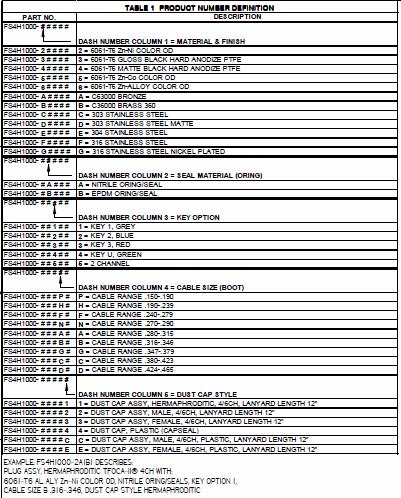
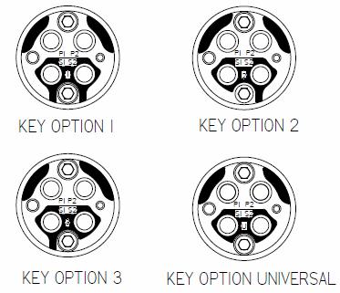
13 3. TFOCA-II TFOCA-II connectors are typically used in any type of harsh environment such as military tactical, mining, industrial, broadcast, and oil and gas. The hermaphroditic design is versatile because it allows multiple plugs to be daisy chained. The connectors are used with simplex, distribution, and breakout cable. The outer diameter of sub-units can be from 1.6 to 3.0 mm. We recommend that distribution cable be used with plugs and breakout cable be used with receptacles. The plug design allows for 400 lbs. of cable retention strength while protecting the fibers from stress. Various coatings and materials are available depending on the corrosion resistance required; these include zinc nickel, black anodize, zinc cobalt, brass, and stainless steel. The connectors are field repairable and reuse existing parts other than the contacts or termini. Similar keying options should be utilized to ensure proper mating. Four key options are available. a) TFOCA-II Plugs The table and the plug figure below describe the part numbering scheme for ordering the proper plug configuration. It is critical to know the cable outer diameter when choosing the proper configuration (reference column 4). Other connector choices are available in 6, 8, 12, and 24 channel configurations. 13
14 14


15 b) TFOCA-II Receptacles The receptacle figure and table below describe the part numbering scheme for ordering the proper receptacle configuration. Other connector choices are available in 6, 8, 12, and 24 channel configurations. 15
16 4. M28876 Connectors M28876 connectors are typically used with simplex and breakout cable. They can also be used with distribution cable. The sub-units shall be 1.6 to 2.0 mm. 3 mm sub-units should not be used due to the insert cavity ID size. Similar keying options should be utilized to ensure proper mating. Pin inserts are standard for plugs, and socket inserts are standard for receptacles. Pin inserts can be used in receptacles, and socket inserts can be used in plugs upon request. See table for pin and socket part numbers. M28876/ Mode/Fiber Size 4, 8, 31 Channel Plug/Receptacle 4, 8, 31 Channel Plug/Receptacle MM / 62.5 um MM / 50 um SM / 9 um Pin Insert Pin termini, M29504/ C Pin termini, M29504/ C Socket Insert Socket termini, M29504/ C, includes captivator (alignment sleeve) Socket termini, M29504/ C, includes captivator (alignment sleeve) It is important to choose the correct part number depending on the connector type, shell size, insert type, channel count, key designation, terminus type and cable outer diameter. Tables 5.1 through 5.3 and the figure below describe these characteristics. It is also critical to choose the correct backshell designator; one must know the exact cable diameter prior to choosing the correct designator. Table 5.1 Connector Type Backshell PN Receptacle Wall Mount Plug Straight M28876/2 45 M28876/3 90 M28876/4 Straight M28876/7 45 M28876/8 16
17 Receptacle Jam Nut 90 M28876/9 Straight M28876/12 45 M28876/13 90 M28876/14 Shell Size Shell Size Designator Table 5.2 Insert Designator Channel Count 13 B C 23 F Table 5.3 Backshell Maximum Cable Diameter (inches) Designator Shell Size 13 Shell Size 15 Shell Size Multiple dust cap options are available for M28876 connectors per the table below. Connector Type Dust Cap PN Dust Cap Option Comments Plug Receptacle 4 Channel (shell size 13) 8 Channel (shell size 15) 31 Channel (shell size 23) M28876/10B M28876/10C M28876/10F 4 Channel M28876/15B 8 Channel M28876/15C 31 Channel M28876/15F A = Chain w/ fastener B = Chain w/ ring C = Rope w/ fastener D = Rope w/ ring E = Dust cap only 17
18 F. SPARE CABLE, CONNECTOR CHANNELS AND PINOUTS All spare connector channels should utilize dummy termini to maintain sealing for the connector. Spare fibers can be terminated and stored inside certain connector back shells or stored as unterminated fibers. Pinouts shall be specified on the drawing. Hermaphroditic connectors are typically crossed to allow for transmit and receive channel hookups. Loopback pinouts are acceptable as long as the fiber bend radius is not exceeded. Contact the manufacturer when loopbacks are required. G. CABLE BEND RADII - REEL APPLICATIONS AND FORMED CABLE LOOPS Bending fiber optic cable causes attenuation or insertion loss within the cable. Exceeding certain bend radii can cause the fiber to crack or fracture. The recommended bend radius when placing a fiber optic cable on a reel or in a fixed installation is noted below. The radius of the reel core or bend shall be equal to or greater than the minimum bend radius in the table. Cable Type Fiber Optic Cable Minimum Bend Radius As a Multiple of Overall Cable Diameter 10 times overall diameter for multimode cables 20 times overall diameter for single mode cables H. OPTICAL TEST REQUIREMENTS 1. Link Loss Considerations The diagram below shows how system link loss is calculated. Typical loss budgets are determined by the transmitter and receiver specifications. Most receivers can operate with greater than 10 db of loss. It is a good practice to de-rate or add some room for margin when designing optical systems. 18
19 2. Insertion Loss Insertion Loss (IL) is the amount of optical power lost as light is transmitted through a fiber and connections. IL is usually expressed in decibels (db). Insertion loss should be specified for any mated pair (connectors or termini) or fiber optic link (cable assembly) along with the wavelength (850nm 1550nm). It is important to identify which loss is being specified (connection or link). 3. Return Loss or Back Reflection Return Loss (RL) or Back Reflection (BR) refers to the light returned or reflected from a connection or raw cable. Return loss should be specified for any single mode mated pair (connectors or termini) or fiber optic link (cable assembly) along with the wavelength ( nm). Return loss is not normally specified for multimode connections or cables. Please inquire if multimode return loss is required. 19
20 Product Comments ILmax (db) RL or BR (Single mode) TFOCA TFOCA-II, TFOCA-III, THD Utilizes biconic style termini. Obsolete technology NA M D38999 Expanded Beam LC, SC, ST, FC Enhanced versions are available with lower losses. Enhanced versions are available with lower losses. Best practice: utilize same manufacturer within each application if possible to (APC) 55 (APC) 4. Termini End Face Geometry and Visual Requirements Termini end face geometry and visual quality requirements should be specified to optimize the reliability and optical performance of optical links and cable assemblies. Several standards exist within the industry. Manufacturing processes should utilize tools that control these parameters. Reference AFSI s technical paper on End Face Quality Standards for details and further information. 20
21 Sky Communications Network Solutions Nybohovsbacken 23, Stockholm, Sweden Phone: +46 (0)
SECTION 4 TABLE OF CONTENTS
 Contents Introduction LC, SC and ST Series...4-2 Markets and Applications...4-2 International Standard Documents Compliance...4-2 LC Series Features and Benefits...4-3 LC Standard... 4-4 to 4-5 LC for
EZ-MATE CONNECTORS The Complete Family of Multi-Channel Fiber Optic Connectors for Harsh Environment Deployable Systems
 The Complete Family of Multi-Channel Fiber Optic Connectors for Harsh Environment Deployable Systems Overview The OCC EZ-MATE family of hermaphroditic style fiber optic connectors provides the most comprehensive
The Next Generation Connector
 The Next Generation Connector This paper describes a new harsh environment fiber optic connector system designed primarily for use on military shipboard and avionics platforms. The Next Generation Connector
Aerospace Fiber Optics
 Aerospace Fiber Optics AFO 101, Session 2 Fiber Optic Assembly Everett Community College. All rights reserved. 1 Session Learning Objectives After completing this session you should be able to: Work safely
MT-RJ SECURE Product Expansion Now 10 Variants of the MT-RJ SECURE Products
 MT-RJ Product Expansion Now 0 Variants of the MT-RJ Products In response to several customers, the MT-RJ product line has been expanded with an additional six color/key versions. In addition to the original
Product Catalogue. Fiber Optic Assemblies & Adapters. Table of Contents General Description... 2
 Product Catalogue Fiber Optic Assemblies & Adapters Table of Contents 1. General Description... 2 2. Connectors... 3 2.1 SC/UPC... 3 2.2 SC/APC... 3 2.3 FC/UPC... 3 2.4 FC/APC... 3 2.5 ST/UPC... 3 2.6
ARINC 801 Fiber Optic Interconnects for Aerospace & Defense. A Complete End-to-End Solution Featuring Connectors, Termini & Cable Harnesses
 ARINC 801 Fiber Optic Interconnects for Aerospace & Defense A Complete End-to-End Solution Featuring Connectors, Termini & Cable Harnesses We Connect the Aerospace & Defense Industry with High-Speed Data,
Crimplok. Connectors. 3M Crimplok ST* Connector Multimode 1. 3M Crimplok SC Connector Single-mode 2
 3 Crimplok Connectors Quick, easy installation and superior performance To successfully design, install or operate today s fiber optic networks, you need components that offer speed and reliability from
TITLE: FIBER OPTIC SHOCK FIXTURES
 ENGINEERING PRACTICE STUDY TITLE: FIBER OPTIC SHOCK FIXTURES 18 January 2007 STUDY PROJECT 60GP-2006-019 FINAL REPORT Study Conducted By Dave Leight DSCC-VAT Fiber Optic Group Prepared by: Dave Leight
HES HACILAR ELEKTRİK SANAYİ VE TİC.A.Ş.
 Technical Specification Revision/Date: 04/04.15 By N.KARAAĞAÇ Date : 27 February 2015 Cable Type HES Cable Product Number :, Outdoor F/O Cable :FOZZXXXSJSA41JYY (ZZ: fiber type G652=SD, G657 A1 = A1, G657
Automatic Connector MHV Connectors MHV Introduction MHV series connectors Contents Polarized mating interfaces Anti-Rock mating interfaces
 Automatic s 2004 Automatic. All rights reserved. pdf 1.0 3-18-04 Contents Specifications........................... 2 Straight Cable Plugs...................... 3 Right Angle Cable Plugs...................
TECHNICAL SPECIFICATION
 ISSUED : OCT. 02, 2006 PAGE : 1 OF 9 REV. : 1 TECHNICAL SPECIFICATION FOR GST 2006-043A LOOSE TUBE DRY CORE CABLE SINGLE JACKET/SINGLE ARMOR (SJSA CABLE) Prepared By : Oh-Heoung Kwon Engineer Optical Technical
TE Connectivity DEUTSCH DL Series MIL-DTL Series III Connectors
 Applications Features TE Connectivity DEUTSCH DL Series MIL-DTL-83723 Series III Connectors High-performance military aircraft Commercial aircraft Communications equipment Armored personnel carriers &
SPECIAL SPECIFICATION 6559 Telecommunication Cable
 2004 Specifications CSJ 0015-09-147, etc. SPECIAL SPECIFICATION 6559 Telecommunication Cable 1. Description. This specification governs the materials, installation, termination, splicing, testing, training,
PERFORMANCE SPECIFICATION SHEET CONNECTORS, PLUGS, ELECTRICAL, COAXIAL RADIO FREQUENCY, (SERIES TNC (CABLED), PIN CONTACT, RIGHT ANGLE, CLASS 2)
, PIN CONTACT, RIGHT ANGLE, CLASS 2)") INCH-POUND MIL-PRF-39012/30H 15 March 2018 SUPERSEDING MIL-PRF-39012/30H w/amendment 3 15 April 2017 PERFORMANCE SPECIFICATION SHEET CONNECTORS, PLUGS, ELECTRICAL, COAXIAL RADIO FREQUENCY, (SERIES TNC
INCH-POUND MIL-PRF-39012/30H 15 March 2018 SUPERSEDING MIL-PRF-39012/30H w/amendment 3 15 April 2017 PERFORMANCE SPECIFICATION SHEET CONNECTORS, PLUGS, ELECTRICAL, COAXIAL RADIO FREQUENCY, (SERIES TNC
Cable Jacket - The outermost layer of the fiber cable. Application: Types Single mode Multi mode. Simplex or Duplex available
 Fiber Optic Products FIBER OPTIC PRODUCTS FIBER OPTIC PATCH CORD CABLE The Construction of a Fiber-Optic Cable Cable Jacket - The outermost layer of the fiber cable. Strengthening fibers - The strengthening
SPECIAL SPECIFICATION 8540 Telecommunication Cable
 2004 Specifications CSJ 0914-00-307 & CSJ 0914-25-003 SPECIAL SPECIFICATION 8540 Telecommunication Cable 1. Description. This specification governs the materials, installation, termination, splicing, testing,
INCH-POUND MIL-PRF-39012/28H w/amendment 4 25 January 2018 SUPERSEDING MIL-PRF-39012/28H w/amendment 3 15 April 2017
 INCH-POUND MIL-PRF-39012/28H 25 January 2018 SUPERSEDING MIL-PRF-39012/28H w/amendment 3 15 April 2017 PERFORMANCE SPECIFICATION SHEET CONNECTORS, RECEPTACLES, ELECTRICAL, COAXIAL, RADIO FREQUENCY, (SERIES
We will look first at the cable, and then the transceivers (which act as both transmitter and receiver on each end of the fiber cable).
.") Nuclear Sensors & Process Instrumentation Fiber Cable Basics Fiber-optic communication is a method of transmitting information from one place to another by sending light through an optical fiber. The light
Nuclear Sensors & Process Instrumentation Fiber Cable Basics Fiber-optic communication is a method of transmitting information from one place to another by sending light through an optical fiber. The light
8D with High Frequency Coaxial Contact
 8D Series M Coaxial Contacts 8D with High Frequency Coaxial Contact robust and powerfull coaxial High Frequency transmission (M) now available in any size 8 SOURIU insert of D38999 Series III. Spring HF
Cable Sets. Deployable reel available. Singlemode & multimode types. MIL Conformant Tactical Cable
 Indigenous Source of Hi-Performance Fiber Optic & Hybrid Cable Sets for Harsh Environment, Naval Systems, Radar Links, Nuclear Customers: ADE, BELs, CAT, DEAL, DLRL, LRDE, HAL, Tata Power, RCI, SAC. Hi-performance
Fiber Optics Redefined
 Fiber Optics Redefined Questions and Answers on the basics of fiber optic installation TECHLOGIX NETWORX Questions & Answers Questions and Answers Q: What are the two main types of fiber? A: The two main
MCX - 75 Ohm Connectors
 133-8333-001 4 133-8333-401 4 133-8334-001 4 133-8334-401 4 133-8433-001 3 133-8433-101 3 133-8434-001 3 133-8445-001* 3 133-8445-101* 3 133-8701-201 5 133-8701-211 5 133-8701-301 6 133-8701-311 6 133-8701-401
SC Type Fiber Optic Connectors
 SC Type Fiber Optic Connectors HSC Series Features 1. JIS, IEC standards compliant and fully intermateable with NTT's SC products. JIS C 573 (F4 type fiber optic connectors) IEC 61754-4 2. Plugs with strain
OPTICAL CHARACTERISTICS (applied to 12c MPO/MTP ) Item Parameter Reference
 Item Parameter Reference") MPO/MTP TRUNK CABLE FEATURES MTP (US Conec) brand or MPO standard compliant multifiber connector Connector's design complies with IEC 61754-7 standards 4, 8, 12 and 24-fiber with single mode and multimode
MPO/MTP TRUNK CABLE FEATURES MTP (US Conec) brand or MPO standard compliant multifiber connector Connector's design complies with IEC 61754-7 standards 4, 8, 12 and 24-fiber with single mode and multimode
PERFORMANCE SPECIFICATION SHEET CONNECTORS, PLUGS, ELECTRICAL, COAXIAL RADIO FREQUENCY, (SERIES BNC (CABLED), PIN CONTACT, CLASS 2)
, PIN CONTACT, CLASS 2)") INCH-POUND MIL-PRF-39012/16H 16 November 2006 SUPERSEDING MIL-PRF-39012/16G 26 September 1994 PERFORMANCE SPECIFICATION SHEET CONNECTORS, PLUGS, ELECTRICAL, COAXIAL RADIO FREQUENCY, (SERIES BNC (CABLED),
INCH-POUND MIL-PRF-39012/16H 16 November 2006 SUPERSEDING MIL-PRF-39012/16G 26 September 1994 PERFORMANCE SPECIFICATION SHEET CONNECTORS, PLUGS, ELECTRICAL, COAXIAL RADIO FREQUENCY, (SERIES BNC (CABLED),
SPECIAL SPECIFICATION 6191 Fiber Optic Cable
 2004 Specifications CSJ 0014-02-014, etc SPECIAL SPECIFICATION 6191 Fiber Optic Cable 1. Description. Furnish, install, splice, field terminate, and test the fiber optic cables. 2. Materials. A. General
MILITARY FIBER OPTIC SOLUTIONISTS
 2017-18 A WOMAN OWNED SMALL BUSINESS FIS BLUE MILITARY FIBER OPTIC SOLUTIONISTS MINING, OIL & GAS Get Fiber'ed up! FIS Blue is an ISO 9001-2008 CERTIFIED quality organization. UNITED REGISTRAR OF SYSTEMS
Fibre Optic Cable & Connector Guide
 Fibre Optic Cable & Connector Guide White paper White Paper Fibre Optic Cable & Connector Guide v1.0 EN 1 Introduction Organising through cables and connectivity options can be an exasperating exercise.
SPECIAL SPECIFICATION 1291 Fiber Optic Video Data Transmission Equipment
 1993 Specifications CSJ 0500-01-117 SPECIAL SPECIFICATION 1291 Fiber Optic Video Data Transmission Equipment 1. Description. This Item shall govern for the furnishing and installation of Fiber Optic Video
1995 Metric CSJ SPECIAL SPECIFICATION ITEM 6031 SINGLE MODE FIBER OPTIC VIDEO TRANSMISSION EQUIPMENT
 1995 Metric CSJ 0508-01-258 SPECIAL SPECIFICATION ITEM 6031 SINGLE MODE FIBER OPTIC VIDEO TRANSMISSION EQUIPMENT 1.0 Description This Item shall govern for the furnishing and installation of color Single
Lensed Fibers & Tapered Ends Description:
 Lensed Fibers & Tapered Ends Description: LaseOptics Corporation ( LaseOptics ) has been producing next generation optical lensed fibers. LaseOptics Lensed Optical Fibers technology is proprietary integrated
To select a fibre optic cable, you have to make choices of the fibre selection and the cable construction selection.
 Fibre Optic Cables & Connectors Guide Introduction Organising through cables and connectivity options can be an exasperating exercise. It's tough enough working through the categories and levels of copper
SPECIAL SPECIFICATION 6735 Video Optical Transceiver
 2004 Specifications CSJ 0924-06-244 SPECIAL SPECIFICATION 6735 Video Optical Transceiver 1. Description. This Item governs the furnishing and installation of Video optical transceiver (VOTR) in field location(s)
SPECIAL SPECIFICATION 1987 Single Mode Fiber Optic Video Transmission Equipment
 1993 Specifications CSJ 0027-12-086, etc. SPECIAL SPECIFICATION 1987 Single Mode Fiber Optic Video Transmission Equipment 1. Description. This Item shall govern for the furnishing and installation of color
Assembly code page 46. Cable code page 47. Assembly classes page 48. Polarization maintaining assemblies page 52
 cable assemblies Assembly code page 46 Cable code page 47 Assembly classes page 48 Polarization maintaining assemblies page 52 45 Assembly: Ordering code Description cable type 27H01CD0- see cable code
SPECIAL SPECIFICATION 6911 Fiber Optic Video Data Transmission Equipment
 2004 Specifications CSJ 3256-02-079 & 3256-03-082 SPECIAL SPECIFICATION 6911 Fiber Optic Video Data Transmission Equipment 1. Description. Furnish and install Fiber Optic Video Data Transmission Equipment
DETAIL SPECIFICATION SHEET CONNECTOR, FIBER OPTIC PLUG, CIRCULAR HERMAPHRODITIC, IN-LINE MOUNT, 2 AND 4 POSITIONS, EXPANDED BEAM
 METRIC 23 September 2014 SUPERSEDING B 20 June 2013 DETAIL SPECIFICATION SHEET CONNECTOR, FIBER OPTIC PLUG, CIRCULAR HERMAPHRODITIC, IN-LINE MOUNT, 2 AND 4 POSITIONS, EPANDED BEAM This specification is
Non Magnetic Connectors
 Non Magnetic Connectors Johnson Components builds coaxial connectors using innovative materials and design to provide Mil Spec Performance at a commercial price. Now we offer our Non Magnetic Connectors
PERFORMANCE SPECIFICATION SHEET CONNECTORS, PLUGS, ELECTRICAL, COAXIAL RADIO FREQUENCY, (SERIES BNC (CABLED), PIN CONTACT, CLASS 2)
, PIN CONTACT, CLASS 2)") PERFORMANCE SPECIFICATION SHEET MIL-PRF-39012/16H 03 January 2017 SUPERSEDING MIL-PRF-39012/16H w/amendment 1 20 April 2009 CONNECTORS, PLUGS, ELECTRICAL, COAXIAL RADIO FREQUENCY, (SERIES BNC (CABLED),
PERFORMANCE SPECIFICATION SHEET MIL-PRF-39012/16H 03 January 2017 SUPERSEDING MIL-PRF-39012/16H w/amendment 1 20 April 2009 CONNECTORS, PLUGS, ELECTRICAL, COAXIAL RADIO FREQUENCY, (SERIES BNC (CABLED),
SMA - 50 Ohm Connectors
 Alphabetical Index 142-0593-001 6 142-0593-006 6 142-0593-401 6 142-0593-406 6 142-0594-001 6 142-0594-006 6 142-0594-401 6 142-0594-406 6 142-0693-001 4 142-0693-006 4 142-0693-051 5 142-0693-056 5 142-0693-101
SC Connector. Fiber Optic Connectors. MDR Electronics
 SC Connector Fiber Optic Connectors MDR Electronics www.mdrelectronics.com Table of contents 1. Introduction 3 2. Image and line drawing 4 3. Types of connector 5 4. Specifications 6 5. Ask for assistance
PREMIUM 5e F/UTP PRODUCTS
 Siemon s end-to-end cabling system is guaranteed to provide transmission performance margins in excess of industry standards for category 5e parameters, while featuring excellent EMI resistance. has been
Part Number (used with PRO-CRIMPER Tool Frame ) for 50 Ohm BNC Dual Crimp MIL Type Connectors
 for 50 Ohm BNC Dual Crimp MIL Type Connectors") Application Tooling Hand Tools CERTI-CRIMP Hand Tools are our top-of-the-line crimping tools featuring the original ratcheted crimp control. All tools are designed to exacting specifications, and manufactured
Application Tooling Hand Tools CERTI-CRIMP Hand Tools are our top-of-the-line crimping tools featuring the original ratcheted crimp control. All tools are designed to exacting specifications, and manufactured
SERIES BNC 50, COAXIAL MINIATURE CONNECTORS
 SERIES BNC 50, COAXIAL MINIATURE CONNECTORS DESCRIPTION CONTENTS PAGE HUBER+SUHNER BNC is still one of the most popular connector series, featuring a two stud bayonet coupling mechanism, which is particularly
HN Connectors. Automatic Connector. Introduction. Contents. 631/ FAX 631/
 Connectors Introduction 2004 Automatic Connector. All rights reserved. pdf 1.0 4-13-04 Contents Specifications........................... 2 Straight Cable Plugs...................... 3 Right Angle Cable
Crimp & Cleave Termination Instructions for SEL ST Connectors
 Your Optical Fiber Solutions Partner Crimp & Cleave Termination Instructions for SEL ST Connectors For Use With: ST Termination Kit (SEL, Part Number BT05402-01) 200 µm HCS Fiber-Optic Cable ST Crimp &
HI-DEX PRODUCT SET DATASHEET
 APPLICATION HI-DEX is an ultra high-performance, pre-terminated and modular optical fibre cabling system based on MT ferrule connector technology. This product set is designed for installationn in the
INCH-POUND MIL-PRF-39012/29H w/amendment 3 25 January 2018 SUPERSEDING MIL-PRF-39012/29H w/amendment 2 21 November 2016
 INCH-POUND MIL-PRF-39012/29H 25 January 2018 SUPERSEDING MIL-PRF-39012/29H w/amendment 2 21 November 2016 PERFORMANCE SPECIFICATION SHEET CONNECTORS, RECEPTACLE, ELECTRICAL, COAXIAL, RADIO FREQUENCY, (SERIES
OptiSPEED LC Keyed Red to Unconnectorized, Fiber Pigtail, 0.9 mm Tight Buffer, 12-fiber Kit, Blue - Aqua (1-12)
") FAML1UC0C OptiSPEED LC Keyed Red to Unconnectorized, Fiber Pigtail, 0.9 mm Tight Buffer, 12-fiber Kit, Blue - Aqua (1-12) Fiber Type Total Fibers, quantity 12 Cord Length, maximum 23 ft 7 m Cord Length,
FAML1UC0C OptiSPEED LC Keyed Red to Unconnectorized, Fiber Pigtail, 0.9 mm Tight Buffer, 12-fiber Kit, Blue - Aqua (1-12) Fiber Type Total Fibers, quantity 12 Cord Length, maximum 23 ft 7 m Cord Length,
 www.mete-enerji.com.tr INDUSTIAL IEC PLUGS AND SOCKETS INDUSTIAL IEC PLUGS AND SOCKETS Position of the Earthing Contact acc. to IEC 60309-2 225/400-265/460 V~ 60 Hz (1) 3 P+N+ 3 P+ 2 P+ 120/208-144/250V~
Public Works Division Lighting District Fiber Optic Specifications April 2009
 Public Works Division Lighting District Fiber Optic Specifications April 2009 7000 Florida Street Punta Gorda, Florida 33950 Tele: 941.575.3600 Fax : 941.637.9265 www.charlottecountyfl.com/publicworks
SPECIAL SPECIFICATION 2284 Fiber Optic Cable (Self-Supporting)
") 2004 Specifications CSJ 0086-14-046 SPECIAL SPECIFICATION 2284 Fiber Optic Cable (Self-Supporting) 1. Description. Furnish, install, splice, field terminate, and test the fiber optic cables. 2. Materials.
2004 Specifications CSJ 0086-14-046 SPECIAL SPECIFICATION 2284 Fiber Optic Cable (Self-Supporting) 1. Description. Furnish, install, splice, field terminate, and test the fiber optic cables. 2. Materials.
UNSIGNED HARDCOPY NOT CONTROLLED
 SUBJECT: APPROVED BY STATUS PURPOSE AFFECTED FUNCTIONS REFERENCES Cable and Harness Making Manager, Hardware Engineering Maintenance Revision Establishes requirements for the fabrication and inspection
DETAIL SPECIFICATION SHEET CONNECTORS, PLUG, ELECTRICAL, RFI SHIELDED, SERIES 2, CRIMP TYPE, BAYONET COUPLING, CLASSES A, D, L, T, W AND K
 INCH-POUND MS3475G 27 October 2015 SUPERSEDING MS3475G 11 March 2015 DETAIL SPECIFICATION SHEET CONNECTORS, PLUG, ELECTRICAL, RFI SHIELDED, SERIES 2, CRIMP TYPE, BAYONET COUPLING, CLASSES A, D, L, T, W
1993 Specifications CSJ SPECIAL SPECIFICATION ITEM Fiber Optic Cable System
 1993 Specifications CSJ 0008-12-071 SPECIAL SPECIFICATION ITEM 6540 Fiber Optic Cable System 1.0 Description. This item shall govern for the furnishing and installation of fiber optic cables in designated
Jumpers & Pigtails. Fiber Type OM1, OM3, OM4, 0S1/OS2. Polarity Correction SC and LC duplex clip allows for polarity correction
 XGLO and LightSystem Jumpers & Pigtails XGLO fiber optic cable assemblies are ideal for supporting duplex and simplex fiber applications over extended distances and next-generation backbones. XGLO cable
Fiber Optic Testing. The FOA Reference for Fiber Optics Fiber Optic Testing. Rev. 1/31/17 Page 1 of 12
 Fiber Optic Testing Testing is used to evaluate the performance of fiber optic components, cable plants and systems. As the components like fiber, connectors, splices, LED or laser sources, detectors and
SECTION 683 VIDEO OPTICAL TRANSCEIVER WITH BI-DIRECTIONAL DATA CHANNEL DESCRIPTION
 683 SECTION 683 VIDEO OPTICAL TRANSCEIVER WITH BI-DIRECTIONAL DATA CHANNEL DESCRIPTION 683.01.01 GENERAL A. The Contractor shall furnish the designated quantity of Video Optical Transceiver (VOTR) pairs
3M Fiber Optic Wall Mount Enclosure 8430 Series
 3M Fiber Optic Wall Mount Enclosure 8430 Series Installation Instructions January 2014 3 78-0013-9429-1-A Table of Contents 1.0 Description...3 2.0 Parts...4 3.0 Assembly...4 4.0 Mounting the Enclosure...6
Follow The Leader In Shielded Technology
 1970s Vampire Tap 1990s Shielded Modular Jack 190s 4 Position Data Connector Follow The Leader In Shielded Technology The new AMP-TWIST Jack is our latest shielded product evolution. It can be terminated
TE Connectivity DEUTSCH ACT Series MIL-DTL Series III Composite Connectors
 TE Connectivity DEUTSCH ACT Series MIL-DTL-38999 Series III Composite Connectors APPLICATIONS FEATURES High-performance military aircraft Commercial aircraft Communications equipment Armored personnel
Mining and Petrochemical Fiber Optic Cables
 Features and Benefits Loose construction Stable and highly reliable transmission parameters Waterblocking technology Allows efficient and craft-friendly cable preparation in outdoor or indoor/outdoor applications
Delaware County Community College Project # Marple Campus Renovation - Phase % Construction Documents November 23, 2011
 SECTION 271323 - COMMUNICATIONS OPTICAL FIBER BACKBONE CABLING PART 1 - GENERAL 1.1 DESCRIPTION A. This section provides the specifications for the work related to the optical fiber system in the project.
FREEDM Loose Tube Interlocking Armored Cables
 features and benefits Flexible, interlocking armor design Gel-free waterblocking technology Color-coded tubes and fibers UV-resistant, flameretardant jacket UV-Resistant Flame-Retardant Outer Jacket InterlockingArmor
The World Of Professional Fiber Optics. safe flexible reliable
 The World Of Professional Fiber Optics safe flexible reliable CONTENTS Contents General Info.... 3 2-Channel System.... 6 4-Channel System.... 10 SMPTE System.... 15 Patchcords.... 19 Accessories.... 21
Fibre Optic Connectors
 Fibre Optic Connectors Expanded Beam - Fibre Optic Connectors D38999 Derived Expanded Beam Connectors for Harsh Enviroment Applications NCAGE Code U5792 www.polamco.com Expanded Beam - Fibre Optic Connectors
INSTALLATION GUIDE. LANmark-OF Zone Distribution Box
 LANmark-OF Zone Distribution Box INSTALLATION GUIDE LANmark-OF Zone Distribution Box Document information Release November 2004 Published by Contact address Nexans Cabling Solutions Alsembergsesteenweg
Stainless Steel SMA Connectors Product Catalog
 Stainless Steel SMA Connectors Product Catalog Connectivity...for Stainless Steel SMA Connectors Connectivity...for Johnson Stainless Steel SMA Connectors meet or exceed the performance requirements of
for FOSTEC INC. 1/ 15
 TECHNICAL SPECIFICATION for OPTICAL FIBER PATCH CORD / PIGTAIL FOSTEC / 5 . Scope: This specification is applicable to optical fiber patch cord, pigtail and with w optical connectors. The pigtail is single
Coastal Carolina University RE-BID WILLIAMS BRICE RENOVATION AND REPAIR October 19, 2018 Construction Documents
 PART 1 - GENERAL 1.1 SUMMARY SECTION 271500 COMMUNICATIONS HORIZONTAL CABLING A. Section Includes: 1. UTP cabling. 2. Telecommunications outlet/connectors. 3. Cabling system identification products. 1.2
SPECIFICATION 96F SM LOOSE TUBE, DRY CORE MINI CABLE
 Revision No.:01 Date: 07.10.06 SPECIFICATION OF 96F SM LOOSE TUBE, DRY CORE MINI CABLE PART NO.:D-96/SM/MTY(F)-MFN-O6.3 Checked By: Pavan Maheshwari Process Associate Design & Development Team Approved
MU Connector Series. Single Mode Small Form Factor Connector. qhigh quality, high precision Ø qinternational standard IEC FEATURES
 MU Connector Series Single Mode Small Form Factor Connector FEATURES qhigh quality, high precision Ø 1. zirconia ferrule produced by SII s integrated production process from molding to final inspection.
SPECIFICATION 192F SM LOOSE TUBE, DRY CORE MINI CABLE
 Revision No.:00 Date: 08.03.2010 SPECIFICATION OF 192F SM LOOSE TUBE, DRY CORE MINI CABLE PART NO.:D-192/SM/MTY(F)-MFN-O9.1 Checked By: Pavan Maheshwari Process Associate Design & Development Team Approved
TE Connectivity DEUTSCH DJT Series MIL-DTL Series I Connectors
 Applications Features TE Connectivity DEUTSCH DJT Series MIL-DTL-38999 Series I Connectors High-performance military aircraft Commercial aircraft Communications equipment Armored personnel carriers & tanks
SUHNER QMA SUBMINIATURE CONNECTORS
 SUHNER QMA SUBMINIATURE CONNECTORS Description Content Page SUHNER QMA coaxial connectors are available with 50 Ω impedance. The frequency range extends to 11 GHz, depending on the connector and cable
ULTIMATE SNAP-N-SEAL
 ULTIMATE SNAP-N-SEAL F Series Compression Connectors Thomas & Betts introduces the Ultimate Snap-N-Seal Compression Connector, the newest addition to the Snap-N-Seal system. Look for the classic design
Selection of a cable depends on functions such as The material Singlemode or multimode Step or graded index Wave length of the transmitter
 Fibre Optic Communications The greatest advantage of fibre cable is that it is completely insensitive to electrical and magnetic disturbances. It is therefore ideal for harsh industrial environments. It
Series MCX 50 micro miniature connectors
 Series MCX 50 micro miniature connectors Description Content MCX 50 HUBER+SUHNER MCX micro miniature snap-on connectors offer you an excellent blend of size,weight, durability and performance for applications
Low Loss RG 402 Equivalent
 421-671 Low Loss RG 402 Equivalent Section 10 Low Loss RG 402 Equivalent In applications that require the bendability of solid dielectric, but with the low loss that only a low density Teflon dielectric
FIBRE OPTIC CABLE SOLUTIONS
 point2point FIBRE OPTIC CABLE SOLUTIONS Introduction From patch-leads through to cross-site cables, or optical adapters through to patch panels, PPM s one-stopshop approach to fibre optic cable management
Non Magnetic Connectors Product Catalog
 Non Magnetic Connectors Product Catalog Introduction Johnson s Non-Magnetic Connector Additions Offer Solutions to MR Imaging Technology Johnson, a product line of Cinch Connectivity Solutions, has expanded
F I B R E Y O U C A N T R U S T
 FIBRE YOU CAN TRUST Deployable Fibre Solutions Fibre optic cables are the only option if you want to move high data rates over long distances. They are incredibly well suited to temporary connections as
PERFORMANCE SPECIFICATION SHEET CONNECTORS, PLUGS, ELECTRICAL, COAXIAL, RADIO FREQUENCY (SERIES SMA (CABLED) - PLUG, PIN CONTACT, CLASS 2)
 - PLUG, PIN CONTACT, CLASS 2)") INCH-POUND MIL-PRF-39012/55G 6 February 2008 SUPERSEDING MIL-PRF-39012/55G 6 January 2006 PERFORMANCE SPECIFICATION SHEET CONNECTORS, PLUGS, ELECTRICAL, COAXIAL, RADIO FREQUENCY (SERIES SMA (CABLED) -
INCH-POUND MIL-PRF-39012/55G 6 February 2008 SUPERSEDING MIL-PRF-39012/55G 6 January 2006 PERFORMANCE SPECIFICATION SHEET CONNECTORS, PLUGS, ELECTRICAL, COAXIAL, RADIO FREQUENCY (SERIES SMA (CABLED) -
Introduction to Fiber Optic Cable Technology Jerry Bednarczyk, PE Course Content
 Introduction to Fiber Optic Cable Technology Jerry Bednarczyk, PE Course Content Page 1 of 10 GENERAL A fiber optic cable system is very similar to a copper wire system in that it is used to transmit data
NC-1000 INSTALLATION MANUAL NC-1000 FIBRE OPTIC CROSS-CONNECTION SYSTEM
 NC-1000 INSTALLATION MANUAL NC-1000 FIBRE OPTIC CROSS-CONNECTION SYSTEM Content 1. General 5 2. The products of NC-1000 system 6 3. Mounting of the frame 8 4. Earthing of the frame 8 NC-1000 FIBRE OPTIC
A. All communications equipment rooms shall be installed in a neat and workmanlike manner.
 SECTION 27 11 00 - COMMUNICATIONS EQUIPMENT ROOM FITTINGS PART 1 - GENERAL 1.1 RELATED DOCUMENTS A. Drawings and general provisions of the Contract, including General and Supplementary Conditions and Division
FIST-GCOG2-Dx6. Follow all local safety regulations related to optical fiber plant elements.
 FIST-GCOG2 I N S T A L L A T I O N I N S T R U C T I O N TC-986-IP Rev A, Mar 2017 www.commscope.com FIST-GCOG2-Dx6 Content 1 Introduction 2 General 2.1 Abbreviations 2.2 Kit contents 2.3 Tools 2.4 Accessories
FIS BLUE BROADCAST FIBER OPTIC SOLUTIONISTS. Tel: Toll-free:
 2018 FIS BLUE BROADCAST FIBER OPTIC SOLUTIONISTS Tel: 315 768 8179 Toll-free: 877 347 0091 www.fisblue.com BROADCAST PANELS FIS Blue offers the industry s most comprehensive line of panels and enclosures.
Game on! Plug n play. Plug and play with PryTerms our pre-terminated fibre optic cables. Read more
 Game on! Plug and play with PryTerms our pre-terminated fibre optic cables. Plug n play Read more Plug and play with PryTerms Have you ever been in a potentially dangerous or really cramped place trying
MCX Miniature Coaxial Connectors
 ONLINE CATALOG MCX Miniature Coaxial Connectors 104 John W. Murphy Drive P.O. Box 510 New Haven, CT 06513 www.aepconnectors.com e-mail: aepsales@aepconnectors.com Mating Interfaces MCX Miniature Coaxial
75 Ohm N Male Connector Crimp/Solder Attachment for RG6
 75 Ohm N Male Connector Crimp/Solder Attachment for RG6 RF Connectors Technical Data Sheet PE4508 Configuration N Male Connector 75 Ohms Straight Body Geometry Features Max Operating Frequency 15 GHz Good
Specification for Loose Tube Fiber Optic Cable (Non-Metallic, Dry Block, Figure-8) (G.652.D)
 (G.652.D)") 2-3, Marunouchi 2-chome, Chiyoda-ku, Tokyo 100-8322, Japan No. FB-KL4001C for Loose Tube Fiber Optic Cable (Non-Metallic, Dry Block, Figure-8) (G.652.D) Aug 2014 1 1. General This specification describes
2-3, Marunouchi 2-chome, Chiyoda-ku, Tokyo 100-8322, Japan No. FB-KL4001C for Loose Tube Fiber Optic Cable (Non-Metallic, Dry Block, Figure-8) (G.652.D) Aug 2014 1 1. General This specification describes
FIBER OPTIC POSITRONIC INDUSTRIES. Interconnection Systems. RoHS Compliant Options Available! Catalog A-011 Rev.
 FIBER OPTIC Interconnection Systems RoHS Compliant Options Available! POSITRONIC INDUSTRIES Catalog A-11 Rev. NC FIBER OPTIC End Face Geometry Example of an Interferometer 3D Photograph 2 Typical Distribution
SECTION 10 BNC / BNC 75 HDTV / BNC-TRX R141 / R142 / R266
 SECTION 10 10 BNC / BNC 75 HDTV / BNC-TRX R141 / R142 / R266 Contents Introduction... 10-4 to 10-5 Interfaces... 10-6 to 10-7 Characteristics... 10-8 to 10-11 Finder guide...10-12 to 10-13 COMPOSITE BNC
SECTION 9 BNC/BNC 75 HDTV/BNC-TRX R141/R142/R266 SIMPLIFICATION IS OUR INNOVATON. Visit for more information
 SECTION 9 BNC/BNC 75 HDTV/BNCTRX R141/R142/R266 SIMPLIFICATION IS OUR INNOVATON Visit www.radiall.com for more information Contents BNC Introduction... 94 to 95 Interfaces... 96 to 97 Characteristics...98
Mustang Series Fast Ethernet, TFOCA II, 100Base- TX / FX Media Converter, Multimode, 1310nM, USB Powered - 5.0VDC
 Mustang Series Fast Ethernet, TFOCA II, 100Base- TX / FX Media Converter, Multimode, 1310nM, USB Powered - 5.0VDC Single Port, Jam Nut, USB Powered FEATURES Compliant with IEEE-802.3:2005 Fast Ethernet
FIS BLUE BROADCAST FIBER OPTIC SOLUTIONISTS. Tel: Toll-free:
 2018 FIS BLUE BROADCAST FIBER OPTIC SOLUTIONISTS Tel: 315 768 8179 Toll-free: 877 347 0091 www.fisblue.com BROADCAST PANELS FIS Blue offers the industry s most comprehensive line of panels and enclosures.
SECTION COMMUNICATIONS HORIZONTAL CABLING
 SECTION 271500 COMMUNICATIONS HORIZONTAL CABLING PART 1 - GENERAL 1.1 SUMMARY A. Section Includes: 1. UTP cabling. 2. Telecommunications outlet/connectors including patch panels. 3. Cabling identification
Sumitomo Cable Specification SE-*RU. OFNP Rated Central Tube Cable with Optical Fibers. Issued: December 2014
 Sumitomo Cable Specification SE-*RU Litepipe Ribbon Indoor Plenum Cable OFNP Rated Central Tube Cable with 12-432 Optical Fibers Issued: December 2014 78 Alexander Drive, Research Triangle Park, NC 27709