E M E - Antenna Controller System - OE5JFL. Block diagram
|
|
|
- Timothy Robinson
- 6 years ago
- Views:
Transcription

1 E M E - Antenna Controller System - OE5JFL Block diagram
2 1.Controller board Page 2 of 12
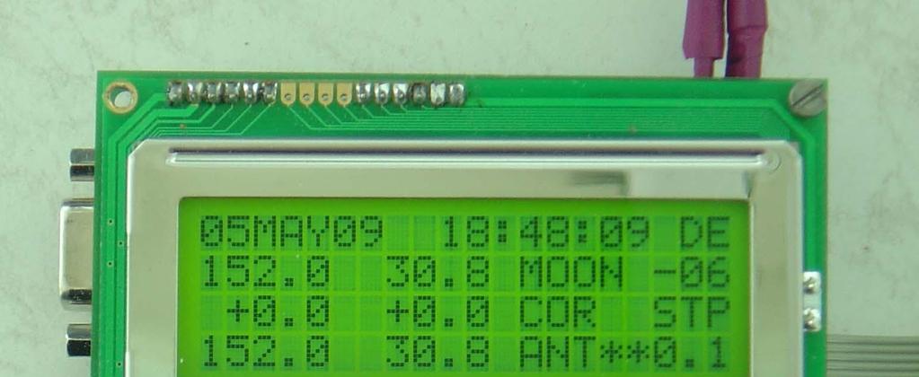
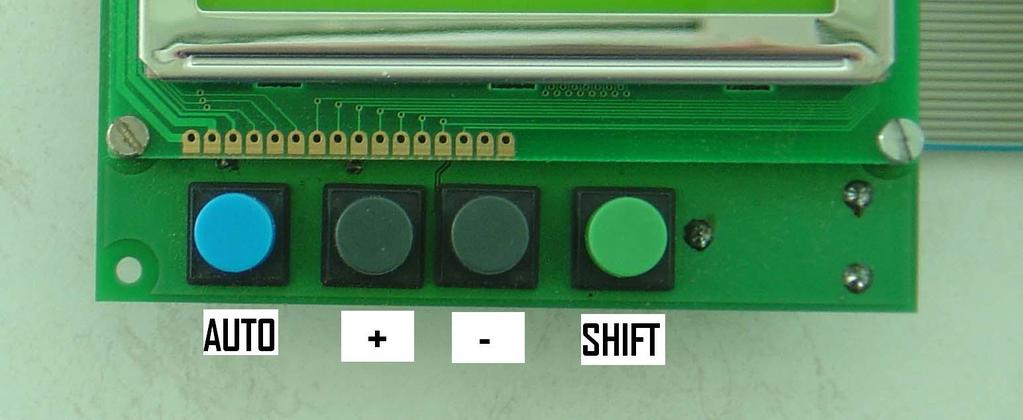
3 Short description of the features - Computation of position (without PC!) for Moon, Sun, Cassiopeia, Cygnus, Sagittarius, Taurus, Leo, Aquarius and a RA/DEC value of free choice - Azimuth and elevation motor controlling for all targets plus two free choice AZ/EL positions - Interfacing with different absolute encoders: 10,11,12 bit SSI (binary,gray) and A2-S-S - Selectable step size for tracking (full, half, quarter resolution) - Selectable offset for azimuth and elevation (+/- 9.9 degrees) - Operation by 4 buttons at controller - Nonvolatile storage of all parameters - Real time clock - 4 x 20 character LCD - display Settings: - All functions and parameters can be set by four buttons on the controller named: SHIFT, +, -, AUTO To run through the setting menu, keep the SHIFT key pressed and press + or key. You will see the cursor blinking at the parameter you choose. For changing the parameter itself, just press + or (SHIFT released). For the first 10 increments or decrements the least significant digit is changed, then the next higher digit is selected. If you press (only) the SHIFT key for more than 5 seconds, Doppler shift is displayed instead of date. For switching back to date display again, press SHIFT for another 5 seconds. To switch between automatic mode on/off, press AUTO key (toggle switch) After changing target, you are always in AUTO OFF mode. In AUTO ON mode you see arrows blinking (output switching signals activated) or asterix when the antenna is in position. Following parameters can be set: antenna offset: +/-9.9 deg in azimuth and elevation step size: full,half,quarter resolution, depending on encoder target: Moon, Sun, Cassiopeia, Cygnus, Sagittarius, Taurus, Leo, Aquarius, RA/DEC, AZ/EL2, AZ/EL1 AZ1,EL1 and AZ2,EL2: free choice antenna positions Right Ascension and Declination for free choice target QTH: longitude, latitude encoder type: (in the moment) SSI for 10,11,12 bit binary, SSI 12bit gray, A2-S-S, MAB25 10,11,12 bit band: for Doppler shift display second, minute, hour, day, month, year MAIN RESET: In some cases (battery empty,..) you might need to make a MAIN RESET: Hold SHIFT key pressed during power on (or together with pressing reset shortly) In that case you have to set again most of the parameters (date, time,..) by running through the menu, because values in the memory were reset to original parameters. FIRMWARE UPDATE: The firmware can be updated via the RS232 port. You need to run Flip software from Atmel (freeware) to load a new HEXfile to the 89C51ED2. Before you have to set the two jumpers on the PCB. Flip settings are at preferences, AutoISP (More) RST(DTR) active Low. When the update is done, remove the jumpers again. REMOTE BY PC: By ASCII commands listed at the end of this documentation it is possible to read and write parameters via a PC COM port. Page 3 of 12

 are activated (low) in automatic mode.")
4 Input/Output: For encoder and motor connection the necessary I/O lines of the controller are provided at a 20pin connector. P1.1 P1.3 P1.5 P1.7 P2.5 P2.7 P3.3 P3.5 GND GND o o o o o o o o o o P1.0 P1.2 P1.4 P1.6 P2.4 P2.6 P3.2 P3.4 +5V +12V o o o o o o o o o o P P1.2 : Az encoder, P1.3 : Az PWM P P1.6 : El encoder, P1.7 : El PWM P2.4, P2.5 : Az motor clw,ccw P2.6, P2.7 : El motor up,down P3.2, P3.3, P3.4, P3.5: future applications You can design your own input/output drivers, or use the interface board described below. 2.Interface board The interface board is connected to the controller board via the 20pin connector. Motor output: The four controller output signals (P2.4 - P2.7) are activated (low) in automatic mode. They are amplified by two MOS H-bridges which can drive DC motors up to 36V/2A. The DC motor inputs must both be isolated from GND!! By setting the two jumpers JP6, JP7 a PWM signal for soft start and slowing down is activated. Page 4 of 12

5 If you want to move the antenna in manual mode, switch auto mode off at the controller, and press the corresponding buttons on the interface board. Encoder Input: It is possible to connect 10bit, 11bit and 12bit binary encoders with 0.5deg, 0.2deg, 0.1deg resolution and 12bit Graycode encoders with the widely used SSI-protocol. To prevent the controller inputs from damage, there are switching transistor stages for each clock output and data input. You have to set the 4 jumpers JP1..JP4 at the transistors, but must let the RS485 sockets without the ICs. You can also connect the well known A2-S-S encoders from US-digital via RS485. In that case the SEI-protocol is used and you have to unplug the four jumpers JP1..JP4 on the board and instead plug the two RS485 drivers into the sockets. I developed an easy to build 0.5deg 10bit encoder, which fits nicely to the controller. But meanwhile a cheap 12bit encoder is available, the MAB25. It s accuracy is worse compared to the A2-S-S, but first measurements showed a maximum deviation of only 0.2deg. Occasionally there was an unstable indication with the MAB25, probably because of pulse reflections. Adding 1k resistors from each encoder pin (CLK,DATA,CS) to GND directly at the encoder or at the splitter board cured the problem. Different encoders will need an updated firmware and maybe a modified hardware connection. If you want reversed indication direction of azimuth (for example if the axis of the encoder is looking downwards), connect pin2(right) and pin3(center) of SL2 (placed in front of CON1) by setting a jumper. A LAN cable is used to connect the encoders. With another jumper you can select the DC for the encoders between 5V or 12V. At the other end of the LAN cable, there is a small splitter PCB for encoder connections. A2-S-S connection Splitter Encoder 0(4) 6: DATA- (blue) 270R 1(5) 5: DATA+ (yellow) MAB25 connection Splitter Encoder +5V VDD 2(6) CS 0(4) CLK 1(5) DATA GND GND PROG (no resistors needed!) +12V 4: +DC (white) 2k2 3: BUSY- (brown) 2k2 2: BUSY+ (green) GND 1: GND (red) At the splitter the pin numbers 0,1,2 for Az and 4,5,6 (in brackets) for El are connected via the LAN cable and the switching transistors to P1.0,..,P1.6 of the 20pin connector. Page 5 of 12
6 3.Circuit diagrams, PCBs and parts lists Circuit diagram controller board Page 6 of 12

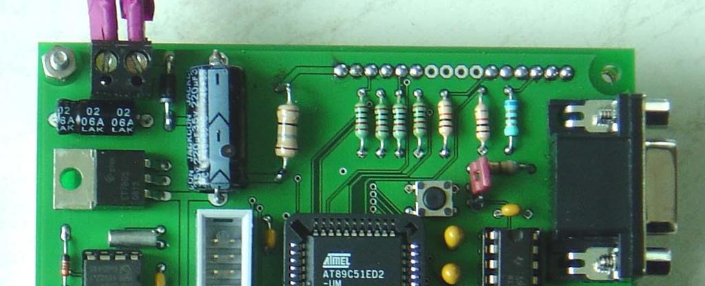
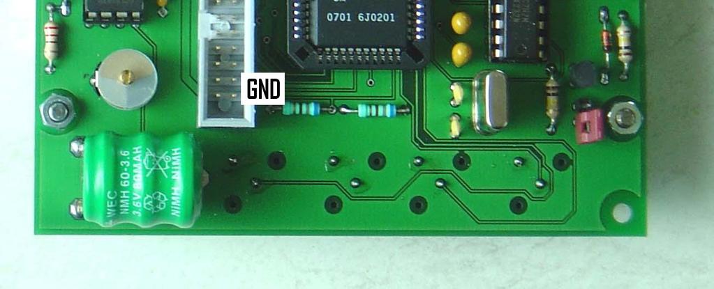
7 PCB controller 1x PCB 1x LCD-Display 4x20 1x 14 pin connector LCD 4x Button 6x 10 k 1x 47 Ohm, 1W 3x 560 Ohm 1x 270 Ohm 1x x 47µF Elko 1x 220µF Elko 1x 1N4004 1x AT89C51ED2 PLCC44 1x IC Socket PLCC44 1x 22,18MHz XTAL 2x 22pF Ker.Ko. 3x 100nF 1x Button RESET 1x DC connector 2pin 1x Connector 2x10 pin 1x PCF8583 DIL8 1x IC Socket DIL8 1x 3V60R Akku 1x 32kHz XTAL 1x 22pF Trimmer capacitor 1x 1N4148 Parts list controller board Page 7 of 12
8 Additionally needed if you want to interface the controller to a PC: 1x 1N4148 1x MAX232 1x IC Socket DIL16 4x 1µF Elko 1x SUB-D 9 fem 1x BC547 2x 100 k 1x 1 k 2x Jumper Circuit diagram motor/encoder interface board Page 8 of 12

9 PCB interface Page 9 of 12
 4 x button 1 x 3pin connector (future application) 1 x 1000µF, 40V 2 x 47µF 2 x 220nF 4 x 100nF 4 x 15nF 2 x 0.")
10 Parts list motor/encoder interface board 1 x PCB 2 x L x BYW98 2 x LTC485 *** 2 x IC socket 8pin *** 1 x x Jumper 2pin 1 x Jumper 3pin 1 x RJ45 LAN connector (fem) 8pin 1 x connector 2x10 pin 3 x connector 2pin (DC, 2x motor) 4 x button 1 x 3pin connector (future application) 1 x 1000µF, 40V 2 x 47µF 2 x 220nF 4 x 100nF 4 x 15nF 2 x 0.5 Ohm, 5W 2 x 2k2 4 x 1k 6 x 22k 2 x 10k 2 x BC547 4 x BC557 *** Only necessary if you are using RS485 for A2-S-S encoders. In that case leave the four jumpers JP1..4 (close to the transistors) open. When using other encoders (MAB25, ), unplug the LTC485 drivers and close the jumpers JP1..4 For Az/El encoder connection you additionally need the small splitter PCB and a 8 pin LAN connector. On the picture two (cheap) MAB25 12bit encoders are connected to the splitter board. *** If you use the A2-S-S, you need additionally on the splitter board: 2 x 270 Ohm, 4 x 2k2 The PCBs were designed with EagleCAD, the files for all boards are available. Page 10 of 12
11 Connecting incremental encoders Although I do not recommend the use of incremental encoders, I have developed a simple microcontroller converter circuit to plug in between each encoder and the splitter board. It reads the encoder output and converts the information to the SSI protocol used by the controller. The circuit needs a quadrature phase signal from the encoder (PHI_A, PHI_B) and a positive reference pulse (REF). The connections to the interface board are the same as for the MAB25 (+DC, GND, CLK, DAT), exception is CS because it is not used here. On the interface board select 12V DC instead of 5V with the jumper. In the controller menu choose SSI_12bit, SSI_11bit or SSI_10bit, depending on the resolution you want to have. Switches SA and SB in the circuit must correspond as follows: both open 12bit, only SA closed to GND 11bit, only SB closed 10bit. With S15 to S0 you have to choose the pulse number per 90 deg of you encoder in binary form. Example: 1024 pulses per 360deg means 256 pulses per 90deg. 256= There is only a single 1 at position 8, therefore S8 has to be switched on, S0 S7 and S9 S15 remain off. As all connections will be permanent, simply connect a wire at the position of S8 to GND, leave all other pins open (including SA, SB positions) and you have 0.1deg resolution. Of course you can not expect a higher resolution than your encoder is providing. The output is limited to a maximum of 12bits. The firmware for the 89C52 microcontroller you can download from the webpage. Circuit diaram for incremental to SSI converter Page 11 of 12
12 ASCII command set for remoting the controller via PC Although the main intention for this controller was to have a system independent of a PC, it might be useful sometimes to remote it. You can read/set each parameter by a row of 6 ASCII characters via the serial port. The speed is fixed to Baud. The principle is, to send from the PC to the controller a question mark (?) if you want to read a parameter, an exclamation mark (!) if you want to set a parameter. Then one letter (a z) must follow to specify the parameter. In the case of reading you will get back four ASCII numbers for the parameter itself, when setting you have to send four ASCII numbers after the letter. For not overloading the controller with commands, you should wait at least 20ms between each read/set action. When reading many parameters, limit it to 20 per second. Parameter table: a: OffsetAz(+100) b: OffsetEl(+100) c: Step d: Target e: Az 2 f: El 2 g: Az 1 h: El 1 i: RA man j: DE man(+900) k: Lon(+1800) l: Lat(+900) m: Encoder n: Dopp1G+5000 o: Az Ant p: El Ant(+900) q: Az Target r: El Target(+900) s: Decl t: Auto u: Sec v: Min w: Hour x: Day y: Month z: Year Most parameters are in 1/10deg. c: 0,1,2 means High, Medium, Low resolution d: Target 0:moon, 1:sun. 10:Az1/El1 m: Encoder 4:A2-S-S, 7:MAB25_12bit n, o, p, q, r, s: read only t: Auto 0:off 1:on; for setting only!t (no numbers!): toggle status Examples: read antenna Az: send?o, wait for 4 numbers means deg set longitude to 13.4 deg East: send!k1666 (1666= ) toggle AUT/MAN status: send!t Page 12 of 12
E M E - Antenna Controller System - OE5JFL. Block diagram
 E M E - Antenna Controller System - OE5JFL Block diagram 1.Controller board Page 2 of 13 Short description of the features - Computation of position (without PC!) for Moon, Sun, Cassiopeia, Cygnus, Sagittarius,
Features of the 745T-20C: Applications of the 745T-20C: Model 745T-20C 20 Channel Digital Delay Generator
 20 Channel Digital Delay Generator Features of the 745T-20C: 20 Independent delay channels - 100 ps resolution - 25 ps rms jitter - 10 second range Output pulse up to 6 V/50 Ω Independent trigger for every
GFT Channel Digital Delay Generator
 Features 20 independent delay Channels 100 ps resolution 25 ps rms jitter 10 second range Output pulse up to 6 V/50 Ω Independent trigger for every channel Fours Triggers Three are repetitive from three
RF Mogul. Quick Start. Model: SDC1. Satellite Dish Controller
 RF Mogul Satellite Dish Controller Model: SDC1 Quick Start 29 February 2012 Minimum required hardware to find a Satellite! This Quick Start document is for connecting and operating a General Dynamics C125M
MENU EXECUTE Shiloh Road Alpharetta, Georgia (770) FAX (770) Toll Free
 FAX (770) Toll Free") Instruction Manual Model 2016-1250 Downconverter May 2009 Rev A F=2501.750 G=+25.0 MENU MODEL 2016 DOWNCONVERTER CROSS TECHNOLOGIES INC. ALARM REMOTE POWER EXECUTE Data, drawings, and other material contained
Instruction Manual Model 2016-1250 Downconverter May 2009 Rev A F=2501.750 G=+25.0 MENU MODEL 2016 DOWNCONVERTER CROSS TECHNOLOGIES INC. ALARM REMOTE POWER EXECUTE Data, drawings, and other material contained
Digital Clock. Perry Andrews. A Project By. Based on the PIC16F84A Micro controller. Revision C
 Digital Clock A Project By Perry Andrews Based on the PIC16F84A Micro controller. Revision C 23 rd January 2011 Contents Contents... 2 Introduction... 2 Design and Development... 3 Construction... 7 Conclusion...
MONITOR POWER Shiloh Road Alpharetta, Georgia (770) FAX (770) Toll Free
 FAX (770) Toll Free") Instruction Manual Model 2099-10xx 10MHz Frequency Source April 2014, Rev. H MENU INTERNAL LEVEL = +10dBm MONITOR POWER 1 2 MODEL 2099 FREQUENCY SOURCE CROSS TECHNOLOGIES INC. ALARM OVEN REMOTE EXECUTE
Instruction Manual Model 2099-10xx 10MHz Frequency Source April 2014, Rev. H MENU INTERNAL LEVEL = +10dBm MONITOR POWER 1 2 MODEL 2099 FREQUENCY SOURCE CROSS TECHNOLOGIES INC. ALARM OVEN REMOTE EXECUTE
MK4 S CONTACTLESS MAGNETOSTRICTIVE LINEAR POSITION TRANSDUCER (SYNCHRONOUS SERIAL OUTPUT)
") MK4 S CONTACTLESS MAGNETOSTRICTIVE LINEAR POSITION TRANSDUCER (SYNCHRONOUS SERIAL OUTPUT) TECHNICAL DATA Measurement taken Position read sampling time (typical) Shock test DIN IEC68T2-27 Vibrations DIN
MK4 S CONTACTLESS MAGNETOSTRICTIVE LINEAR POSITION TRANSDUCER (SYNCHRONOUS SERIAL OUTPUT) TECHNICAL DATA Measurement taken Position read sampling time (typical) Shock test DIN IEC68T2-27 Vibrations DIN
Callisto DISEqC Antenna Tracker
 Callisto DISEqC Antenna Tracker Figure 1: Final product Description The goal of the project was to make an antenna tracker that could not only follow the sun, but also other objects in the sky (moon, Satellite,
Part No. ENC-LAB01 Users Manual Introduction EncoderLAB
 PCA Incremental Encoder Laboratory For Testing and Simulating Incremental Encoder signals Part No. ENC-LAB01 Users Manual The Encoder Laboratory combines into the one housing and updates two separate encoder
N3ZI Digital Dial Manual For kit with Backlit LCD Rev 4.00 Jan 2013 PCB
 N3ZI Digital Dial Manual For kit with Backlit LCD Rev 4.00 Jan 2013 PCB Kit Components Item Qty Designator Part Color/Marking PCB 1 LCD Display 1 LCD 1602 Volt Regulator 1 U1 78L05, Black TO-92 Prescaler
USER'S MANUAL. Getting started with ALEXAN ATMEL AT89C2051/AT89C4051 Training Module - 1
 USER'S MANUAL Getting started with ALEXAN ATMEL AT89C05/AT89C405 Training Module - Version.0 Copyright 006 Ace Electronic Technology Inc. All Rights Reserved Alexan 05/405 TM- v..0 Page of 7 About This
IV 251. Signal Converter SSI => Analogue and SSI => Serial. Operating Instructions. control motion interface
 control motion interface motrona GmbH Zwischen den Wegen 32 78239 Rielasingen - Germany Tel. +49 (0)7731-9332-0 Fax +49 (0)7731-9332-30 info@motrona.com www.motrona.com IV 251 Signal Converter SSI => Analogue
N3ZI Digital Dial Manual For kit with Serial LCD Rev 3.04 Aug 2012
 N3ZI Digital Dial Manual For kit with Serial LCD Rev 3.04 Aug 2012 Kit properly assembled and configured for Standard Serial LCD (LCD Not yet connected) Kit Components Item Qty Designator Part Color/Marking
ET-REMOTE DISTANCE. Manual of ET-REMOTE DISTANCE
 ET-REMOTE DISTANCE ET-REMOTE DISTANCE is Distance Measurement Module by Ultrasonic Waves; it consists of 2 important parts. Firstly, it is the part of Board Ultrasonic (HC-SR04) that includes sender and
IV 251. Signal Converter SSI Analogue and SSI Serial. Operating Instructions. control motion interface
 control motion interface IV 251 Signal Converter SSI Analogue and SSI Serial Suitable for operation with all sensors and encoders using SSI interface Scalable analogue outputs +/- 10 volts, 0-20 ma and
R5 RIC Quickstart R5 RIC. R5 RIC Quickstart. Saab TransponderTech AB. Appendices. Project designation. Document title. Page 1 (25)
") Appendices 1 (25) Project designation R5 RIC Document title CONTENTS 2 (25) 1 References... 4 2 Dimensions... 5 3 Connectors... 6 3.1 Power input... 6 3.2 Video I... 6 3.3 Video Q... 6 3.4 Sync... 6 3.5
Appendices 1 (25) Project designation R5 RIC Document title CONTENTS 2 (25) 1 References... 4 2 Dimensions... 5 3 Connectors... 6 3.1 Power input... 6 3.2 Video I... 6 3.3 Video Q... 6 3.4 Sync... 6 3.5
S6B CH SEGMENT DRIVER FOR DOT MATRIX LCD
 64 CH SEGMENT DRIVER FOR DOT MATRIX LCD June. 2000. Ver. 0.0 Contents in this document are subject to change without notice. No part of this document may be reproduced or transmitted in any form or by
C-MAX. TSG200 Time signal generator TSG200. Time Signal Generator. Manual TSG200. RF Technology Specialist. Version. Revision. SPEC No.
 Manual Time signal generator RF Technology Specialist Time Signal Generator A6 1 of 24 Manual The allows to transmit the time signal in any location. This feature opens a wide range of usage for the, e.g.
Combo Board.
 Combo Board www.matrixtsl.com EB083 Contents About This Document 2 General Information 3 Board Layout 4 Testing This Product 5 Circuit Diagram 6 Liquid Crystal Display 7 Sensors 9 Circuit Diagram 10 About
DMC550 Technical Reference
 DMC550 Technical Reference 2002 DSP Development Systems DMC550 Technical Reference 504815-0001 Rev. B September 2002 SPECTRUM DIGITAL, INC. 12502 Exchange Drive, Suite 440 Stafford, TX. 77477 Tel: 281.494.4505
Instruction Manual Model Block Downconverter
 Instruction Manual Model 3116-7890 Block Downconverter May 2016, Rev. 0 MENU 8.40-1.55 GHZ G=+10.0 REF AUTO-I MODEL 3116 DOWNCONVERTER CROSS TECHNOLOGIES INC. REMOTE ALARM POWER EXECUTE Data, drawings,
64CH SEGMENT DRIVER FOR DOT MATRIX LCD
 64CH SEGMENT DRIVER FOR DOT MATRIX LCD INTRODUCTION The (TQFP type: S6B2108) is a LCD driver LSI with 64 channel output for dot matrix liquid crystal graphic display systems. This device consists of the
DiD. LCD Video Monitor & Video Wall Universal User Manual. Digital Information Display
 LCD Video Monitor & Video Wall Universal User Manual DiD Digital Information Display Video Monitor Models M82S1/M70S1/M65S1/M55S1/M46S1/M40S1/M32S1/M24S1/M19S2/M19S1 Video Wall Models PD55N3/PD46N4/PD46N3/PD46N2/PD40N2
Alice EduPad Board. User s Guide Version /11/2017
 Alice EduPad Board User s Guide Version 1.02 08/11/2017 1 Table OF Contents Chapter 1. Overview... 3 1.1 Welcome... 3 1.2 Launchpad features... 4 1.3 Alice EduPad hardware features... 4 Chapter 2. Software
VLT AutomationDrive FC 301/FC 302
 Introduction The can be used as feedback source for closed-loop control or as master source for synchronizing control. Configure the encoder option in parameter group 17-** Feedback Option, see the VLT
ECE 372 Microcontroller Design
 E.g. Port A, Port B Used to interface with many devices Switches LEDs LCD Keypads Relays Stepper Motors Interface with digital IO requires us to connect the devices correctly and write code to interface
Noise Detector ND-1 Operating Manual
 Noise Detector ND-1 Operating Manual SPECTRADYNAMICS, INC 1849 Cherry St. Unit 2 Louisville, CO 80027 Phone: (303) 665-1852 Fax: (303) 604-6088 Table of Contents ND-1 Description...... 3 Safety and Preparation
Instruction Manual Model Downconverter
 Instruction Manual Model 2016-1351 Downconverter August 2010, Rev. A F=512 G=+0.0 MENU MODEL 2016 DOWNCONVERTER CROSS TECHNOLOGIES INC. ALARM REMOTE POWER EXECUTE Data, drawings, and other material contained
Product Information. EIB 700 Series External Interface Box
 Product Information EIB 700 Series External Interface Box June 2013 EIB 700 Series The EIB 700 units are external interface boxes for precise position measurement. They are ideal for inspection stations
A/D and D/A convertor 0(4) 24 ma DC, 16 bits
 24 ma DC, 16 bits") A/D and D/A convertor 0(4) 24 ma DC, 6 bits ZAT-DV The board contains independent isolated input A/D convertors for measurement of DC current signals 0(4) ma from technological convertors and sensors and
A/D and D/A convertor 0(4) 24 ma DC, 6 bits ZAT-DV The board contains independent isolated input A/D convertors for measurement of DC current signals 0(4) ma from technological convertors and sensors and
PB-507. Advanced Analog & Digital Electronic Design Workstation Instruction Manual. Revision: 2/2014
 PB-507 Advanced Analog & Digital Electronic Design Workstation Instruction Manual Revision: 2/2014 Test Equipment Depot - 800.517.8431-99 Washington Street Melrose, MA 02176 TestEquipmentDepot.com 1 1
ZU 251. Incremental Counter Module With Analogue Output and Serial Interface. Operating Instructions. control motion interface
 control motion interface motrona GmbH Zwischen den Wegen 32 78239 Rielasingen - Germany Tel. +49 (0)7731-9332-0 Fax +49 (0)7731-9332-30 info@motrona.com www.motrona.com ZU 251 Incremental Counter Module
L, LTC, LTM, LT are registered trademarks of Linear Technology Corporation. Other product
 DESCRIPTION WARNING! Do not look directly at operating LED. This circuit produces light that can damage eyes. Demo Circuit 1265 QUICK START GUIDE LTC3220/LTC3220-1 360mA Universal 18-Channel LED Driver
Hardware & software Specifications
 Hardware & software Specifications Réf : PRELIMINARY JUNE 2007 Page 2 of 17 1. PRODUCT OVERVIEW...3 2. TERMINOLOGY...4 A. THE FRONT PANEL...4 B. THE REAR PANEL...5 3. SCREENS DESCRIPTION...5 A. MAIN SCREEN
Total solder points: 123 Difficulty level: beginner 1. advanced AUDIO ANALYZER K8098. audio gea Give your. . high-tech ILLUSTRATED ASSEMBLY MANUAL
 Total solder points: 123 Difficulty level: beginner 1 2 3 4 5 advanced AUDIO ANALYZER K8098 ra audio gea Give your. look high-tech ILLUSTRATED ASSEMBLY MANUAL H8098IP-1 Features & Specifications Features
Vtronix Incorporated. Simon Fraser University Burnaby, BC V5A 1S6 April 19, 1999
 Vtronix Incorporated Simon Fraser University Burnaby, BC V5A 1S6 vtronix-inc@sfu.ca April 19, 1999 Dr. Andrew Rawicz School of Engineering Science Simon Fraser University Burnaby, BC V5A 1S6 Re: ENSC 370
Instruction Manual Model Block Upconverter
 Instruction Manual Model 3115-73 Block Upconverter April 2013, Rev. 0 MENU 7.1-7.3GHZ G=+10.0 REF AUTO MODEL 3115 UPCONVERTER CROSS TECHNOLOGIES INC. REMOTE ALARM POWER EXECUTE Data, drawings, and other
MENU EXECUTE Shiloh Road Alpharetta, Georgia (770) FAX (770) Toll Free
 FAX (770) Toll Free") Instruction Manual Model 2584-31 Combiner May 2011, Rev. A RF MONITOR GAIN = -15 MENU MODEL 2584 COMBINER CROSS TECHNOLOGIES INC. ALARM REMOTE POWER EXECUTE Data, drawings, and other material contained
Instruction Manual Model 2584-31 Combiner May 2011, Rev. A RF MONITOR GAIN = -15 MENU MODEL 2584 COMBINER CROSS TECHNOLOGIES INC. ALARM REMOTE POWER EXECUTE Data, drawings, and other material contained
Ten-Tec (865) Service Department:(865)
 Service Department:(865)") Ten-Tec (865) 453-7172 Service Department:(865) 428-0364 Installation Instructions for Ten-Tec Jupiter AT538K Tuner Kit The installation of the AT538K is divided into two steps. The first step is to reprogram
Ten-Tec (865) 453-7172 Service Department:(865) 428-0364 Installation Instructions for Ten-Tec Jupiter AT538K Tuner Kit The installation of the AT538K is divided into two steps. The first step is to reprogram
MODEL ED32i TTL LINEAR ENCODER
 Reliable non-contact measurement Can be used for rotary as well as linear measurements Differential 5V TTL A/B-Quadrature output Error detection like out of range or missing scale Programmable reference
DDS VFO CONSTRUCTION MANUAL. DDS VFO Construction Manual Issue 1.1 Page 1
 DDS VFO CONSTRUCTION MANUAL DDS VFO Construction Manual Issue 1.1 Page 1 Important Please read before starting assembly STATIC PRECAUTION The DDS VFO kit contains the following components which can be
Foreword: The purpose of this document is to describe how to install and configure Neets 4 relay box
 Foreword: The purpose of this document is to describe how to install and configure Neets 4 relay box COPYRIGHT All information contained in this manual is the intellectual property of and copyrighted material
LED-DEC W07 REMOTE DISPLAY WIRELESS DECODER
 LED-DEC W07 REMOTE DISPLAY WIRELESS DECODER INSTALLATION MANUAL 1. Contents 1. Contents... 1 2. Equipment List... 3 3. Overview... 3 3.1 Introduction... 3 3.2 Location Selection & Cabling *** Important
Controller, Scheduler-Timer Model UCS-01 version User Guide
 Model UCS-01 version 1.48+ User Guide QUICK REFERENCE GUIDE Time Date IDLE SCREEN 03:50PM [RUN] 05/09/06 Tue Day of the Week Schedule Mode (change via 'Set Time') [OFF] = No Events Operate [RUN] = Run
Lab Task 3. Soldering the PCB
 Lab Task 3 Soldering the PCB PCB I:! Use a wire to connect the 5V to pin 7! 2 PCB II 3 PCB Circuit design!! R17 = 25k!!!! R9 = 47k!! 4 Soldering PCB I Step1: Power Supply uc C1 LED3 C6 R4 6 C5 1 Connector
V6118 EM MICROELECTRONIC - MARIN SA. 2, 4 and 8 Mutiplex LCD Driver
 EM MICROELECTRONIC - MARIN SA 2, 4 and 8 Mutiplex LCD Driver Description The is a universal low multiplex LCD driver. The version 2 drives two ways multiplex (two blackplanes) LCD, the version 4, four
USER MANUAL HDMI over IP EXTENDER
 USER MANUAL HDMI over IP EXTENDER Introduction: The HDMIRHRX101120M is a sophisticated many to many HDMI over IP extender. HDCP 2.0 compliant and resolutions up to 1080P full HD and 1920x1200 (WUXGA) are
SPI Serial Communication and Nokia 5110 LCD Screen
 8 SPI Serial Communication and Nokia 5110 LCD Screen 8.1 Objectives: Many devices use Serial Communication to communicate with each other. The advantage of serial communication is that it uses relatively
Good Display Specifications
 Specifications Type: Model No. Description: 5.0inch TFT LCD module GD567M03-GTI050TN22 5.0 LCD with 640 x RGB x 480 dots Supports CVBS/Video & VGA input RoHS Compliant Prepared: Xiaoli Lan Checked: Moon
VIDEO GRABBER. DisplayPort. User Manual
 VIDEO GRABBER DisplayPort User Manual Version Date Description Author 1.0 2016.03.02 New document MM 1.1 2016.11.02 Revised to match 1.5 device firmware version MM 1.2 2019.11.28 Drawings changes MM 2
XTAL Bank DDS Version 0.02 Sept Preliminary, highly likely to contain numerous errors
 XTAL Bank DDS Version 002 Sept 7 2012 Preliminary, highly likely to contain numerous errors The photo above shows the fully assembled Xtal Bank DDS with 2 DDS modules installed (The kit is normally only
Matrix Switcher. Users Guide ANI-VGA ANI-V ANI-RGB
 Matrix Switcher Users Guide ANI-VGA ANI-V ANI-RGB Document version: 052012 For use of the device and safety of users, please follow the instructions when installing, using and maintaining: The system must
R.G.O. 32 BIT CAMAC COUNTER MODULE USER MANUAL
 R.G.O. 32 BIT CAMAC COUNTER MODULE USER MANUAL C.S. Amos / D.J. Steel 16th August 1993 Copyright R.G.O. August 1993 1. General description. 3 2. Encoder formats 3 2.1 A quad B type encoders... 3 2.2 Up/down
ED3. Digital Encoder Display Page 1 of 13. Description. Mechanical Drawing. Features
 Description Page 1 of 13 The ED3 is an LCD readout that serves as a position indicator or tachometer. The ED3 can display: Speed or position of a quadrature output incremental encoder Absolute position
medlab One Channel ECG OEM Module EG 01000
 medlab One Channel ECG OEM Module EG 01000 Technical Manual Copyright Medlab 2012 Version 2.4 11.06.2012 1 Version 2.4 11.06.2012 Revision: 2.0 Completely revised the document 03.10.2007 2.1 Corrected
QUADRANT DVB-T Modulator USER GUIDE. Quadrant DVB A N T E N N A I R. Copyright 2012 Antennair Limited, Neo House, Shaw Road, OLDHAM OL1 4AW. Issue 1.
 QUADRANT DVB-T Modulator USER GUIDE Quadrant DVB A N T E N N A I R Copyright 2012 Antennair Limited, Neo House, Shaw Road, OLDHAM OL1 4AW Issue 1.1 This user guide contains basic instructions for installation
ATLANTA ASF 2033HD+ DVB-S/S2 METER. User`s Manual
 ATLANTA ASF 2033HD+ DVB-S/S2 METER User`s Manual Buttons and Indicators... 2 How to measure... 3 Main menu... 4 LNB Setting... 4 Edit Satellite... 6 Spectrum Chart... 7 Constellation... 9 Angle Calculation...
SignalTap Plus System Analyzer
 SignalTap Plus System Analyzer June 2000, ver. 1 Data Sheet Features Simultaneous internal programmable logic device (PLD) and external (board-level) logic analysis 32-channel external logic analyzer 166
DCP100 Digital Control Programmer Specifications
 DCP100 Digital Control Programmer Specifications EN01-6028 October 1996 Overview The DCP100 is a microprocessor based 1 /4 DIN programmer/controller for process variable versus time control of temperature,
CCE900-IP-TR. User s Guide
 CCE900-IP-TR CCE900-IP-T & CCE900-IP-R User s Guide i-tech Company LLC TOLL FREE: (888) 483-2418 EMAIL: info@itechlcd.com WEB: www.itechlcd.com 1. Introduction The CCE900-IP-T & CCE900-IP-R is a solution
GFT Channel Slave Generator
 GFT1018 8 Channel Slave Generator Features 8 independent delay channels 1 ps time resolution < 100 ps rms jitter for optical triggered delays 1 second range Electrical or optical output Three trigger modes
TRIMBLE GPS / 10MHz REFERENCE MONITOR DISPLAY V January 2015
 TRIMBLE GPS / 10MHz REFERENCE MONITOR DISPLAY V1.2-1.4 January 2015 A display and command module for the Trimble Thunderbolt GPS with 10MHz reference oscillator. by Hubbatech Software Revision Notes: 1.2-2014
DX-10 tm Digital Interface User s Guide
 DX-10 tm Digital Interface User s Guide GPIO Communications Revision B Copyright Component Engineering, All Rights Reserved Table of Contents Foreword... 2 Introduction... 3 What s in the Box... 3 What
Field Service Procedure Replacement PCU Kit, Coastal
 1. Brief Summary: Troubleshooting document for diagnosing a fault with and replacing the PCU assembly on the coastal series antennas. 2. Checklist: Initialization Rate Sensor Outputs Run the Built In Test
Kramer Electronics, Ltd. USER MANUAL. Model: VS-201YC. 2x1 s-video Switcher
 Kramer Electronics, Ltd. USER MANUAL Model: VS-201YC 2x1 s-video Switcher Contents Contents 1 Introduction 1 2 Getting Started 1 2.1 Quick Start 1 3 Overview 3 4 Your VS-201YC 2x1 s-video Switcher 4 5
C8000. sync interface. External sync auto format sensing : AES, Word Clock, Video Reference
 features Standard sync module for a frame Internal sync @ 44.1 / 48 / 88.2 / 96kHz External sync auto format sensing : AES, Word Clock, Video Reference Video Reference : Black Burst (NTSC or PAL) Composite
COPYRIGHT NOVEMBER-1998
 Application Notes: Interfacing AG-132 GPS with G-858 Magnetometer 25430-AM Rev.A Operation Manual COPYRIGHT NOVEMBER-1998 GEOMETRICS, INC. 2190 Fortune Drive, San Jose, Ca 95131 USA Phone: (408) 954-0522
Programmable Video Signal Generator VG-880. Instruction Manual. Ver 1.10
 Programmable Video Signal Generator VG-880 Instruction Manual Ver 1.10 Programmable Video Signal Generator VG-880 Instruction Manual 2009.9 Ver.1.10 ASTRODESIGN,Inc CONTENTS BEFORE OPERATION...v Chapter
Dragon. manual version 1.6
 Dragon manual version 1.6 Contents DRAGON TOP PANEL... 2 DRAGON STARTUP... 2 DRAGON STARTUP SCREEN... 2 DRAGON INFO SCREEN... 3 DRAGON MAIN SCREEN... 3 TURNING ON A TRANSMITTER... 4 CHANGING MAIN SCREEN
imso-104 Manual Revised August 5, 2011
 imso-104 Manual Revised August 5, 2011 Section 1 Getting Started SAFETY 1.10 Quickstart Guide 1.20 SAFETY 1.30 Compatibility 1.31 Hardware 1.32 Software Section 2 How it works 2.10 Menus 2.20 Analog Channel
Kramer Electronics, Ltd. USER MANUAL. Model: VS x 1 Sequential Video Audio Switcher
 Kramer Electronics, Ltd. USER MANUAL Model: VS-120 20 x 1 Sequential Video Audio Switcher Contents Contents 1 Introduction 1 2 Getting Started 1 2.1 Quick Start 2 3 Overview 3 4 Installing the VS-120 in
WaveMaker III Gartech Enterprises Inc. 12/17/2012
 WaveMaker III Gartech Enterprises Inc. 12/17/2012 1 Preface: WaveMaker III standalone unit is produced for those desiring a flexible wave form generator. This unit is capable of providing selectable waveform
Netzer AqBiSS Electric Encoders
 Netzer AqBiSS Electric Encoders AqBiSS universal fully digital interface Application Note (AN-101-00) Copyright 2003 Netzer Precision Motion Sensors Ltd. Teradion Industrial Park, POB 1359 D.N. Misgav,
A Motor can be in many groups, by assigning additional channel# on it.
 Timer Remote Control Instruction How to use the channel numbers - There are 32 channels on the Remote Control Timer you can assign to Curtain Motor(s). To operate the Motors individually by itself only,
MENU EXECUTE Shiloh Road Alpharetta, Georgia (770) FAX (770) Toll Free
 FAX (770) Toll Free") Instruction Manual Model 2083-2717 Block Translator October 2018, Rev. 0 2650>1700 G=-10.0 TRX =950.000000 MHz MENU MODEL 2083 TRANSLATOR CROSS TECHNOLOGIES INC. REMOTE POWER ALARM EXECUTE Data, drawings,
Instruction Manual Model 2083-2717 Block Translator October 2018, Rev. 0 2650>1700 G=-10.0 TRX =950.000000 MHz MENU MODEL 2083 TRANSLATOR CROSS TECHNOLOGIES INC. REMOTE POWER ALARM EXECUTE Data, drawings,
MENU EXECUTE Shiloh Road Alpharetta, Georgia (770) FAX (770) Toll Free
 FAX (770) Toll Free") Instruction Manual Model 2083-2838 Block Translator April 2019, Rev. 0 2700>3850 G=-10.0 REF = AUTO - I MENU MODEL 2083 TRANSLATOR CROSS TECHNOLOGIES INC. REMOTE POWER ALARM EXECUTE Data, drawings, and
Instruction Manual Model 2083-2838 Block Translator April 2019, Rev. 0 2700>3850 G=-10.0 REF = AUTO - I MENU MODEL 2083 TRANSLATOR CROSS TECHNOLOGIES INC. REMOTE POWER ALARM EXECUTE Data, drawings, and
CH-2538TXWPKD 4K UHD HDMI/VGA over HDBaseT Wallplate Transmitter. CH-2527RX 4K UHD HDMI over HDBaseT Receiver. Operation Manual
 CH-2538TXWPKD 4K UHD HDMI/VGA over HDBaseT Wallplate Transmitter CH-2527RX 4K UHD HDMI over HDBaseT Receiver Operation Manual DISCLAIMERS The information in this manual has been carefully checked and
USER MANUAL. Kramer Electronics, Ltd. Models:
 Kramer Electronics, Ltd. USER MANUAL Models: VS-88A, 8 x 8 Balanced Audio Matrix Switcher VS-88V, 8 x 8 Video Matrix Switcher SD-7588V, 8 x 8 SDI Matrix Switcher Contents Contents 1 Introduction 1 2 Getting
Smart-Encoder : Optical Incremental
 1. Introduction The Smart-Encoder effectively eliminates multiple encoder part numbers by bringing intelligence and security to its design. In seconds, a four-digit LED display with two push-buttons enables
Instruction manual Universal Fieldbus-Gateway UNIGATE IC - RS
 Instruction manual niversal Fieldbus-Gateway NIGE IC - S rt.-no.: V3504E Carl-Zeiss-Str. 8 D-65520 Bad Camberg el:+49-(0)6434-9433-0 Hotline: +49-(0)6434-9433-33 Fax: +49-(0)6434-9433-40 Internet: http://www.deutschmann.de
A new generation of access control.
 TM A new generation of access control. 2 or 4 Door Expandable Controller INSTALLATION MANUAL Installation overview: Installation Diagram Switch Alpha 4 Alpha 4 + PoE Alpha 4 + PoE Alarm central Accessory
DIVERSITY DVB-T RECEIVER (DDR)
") User s Manual The most important thing we build is trust. DIVERSITY DVB-T RECEIVER (DDR) Cobham Surveillance GMS Products 1916 Palomar Oaks Way Ste 100 Carlsbad, CA 92008 100-M0062X2 T: 760-496-0055 05/15/09
User s Manual The most important thing we build is trust. DIVERSITY DVB-T RECEIVER (DDR) Cobham Surveillance GMS Products 1916 Palomar Oaks Way Ste 100 Carlsbad, CA 92008 100-M0062X2 T: 760-496-0055 05/15/09
Integrated Circuit for Musical Instrument Tuners
 Document History Release Date Purpose 8 March 2006 Initial prototype 27 April 2006 Add information on clip indication, MIDI enable, 20MHz operation, crystal oscillator and anti-alias filter. 8 May 2006
Yellow Frog. Manual Version 1.1
 Yellow Frog Manual Version 1.1 1 YellowFrog Contents PC Requirements...... 2 YellowFrog Power Meter Measurement.... 3 YellowFrog PC Software..... 3 Main Screen....... 4 Input Overload....... 5 Battery
ZU 252. Incremental Counter Module With Analogue Output and Serial Interface. Operating Instructions. control motion interface
 control motion interface ZU 252 Incremental Counter Module With Analogue Output and Serial Interface Counter suitable for quadrature signals (A/B, 90º) as well as single channel inputs Counting inputs
Night Hawk Firing System User s Manual
 Firmware Version 2.53 Page 1 of 37 Table of Contents Features of the Night Hawk Panel... 4 A reminder on the safe use of Electronic Pyrotechnic Firing Systems... 5 Night Hawk Firing Panel Controls... 6
Introduction 1. Digital inputs D6 and D7. Battery connects here (red wire to +V, black wire to 0V )
") Introduction 1 Welcome to the magical world of GENIE! The project board is ideal when you want to add intelligence to other design or electronics projects. Simply wire up your inputs and outputs and away
Introduction 1 Welcome to the magical world of GENIE! The project board is ideal when you want to add intelligence to other design or electronics projects. Simply wire up your inputs and outputs and away
Revision 1.2d
 Specifications subject to change without notice 0 of 16 Universal Encoder Checker Universal Encoder Checker...1 Description...2 Components...2 Encoder Checker and Adapter Connections...2 Warning: High
HDMI 2x4 Matrix. Operation Manual CHMX-24
 HDMI x4 Matrix Operation Manual CHMX-4 TABLE OF CONTENTS. Introduction.... Features... 3. Package Contents... 4. Operation Controls and Functions... 4. Front Panel... 4. Rear Panel... 4.3 Remote Control...
SAT IF distribution system
 7. Technical specifications Type cs43 RF input frequency range pr. 50-350 MHz inputs number 4 level pr. 55...88 dbµv 60...93 dbµv symbol rate 3 45 Ms/s return loss/impedance > 0 db/75 Ω LNB powering/control
HD-SDI Express User Training. J.Egri 4/09 1
 HD-SDI Express User Training J.Egri 4/09 1 Features SDI interface Supports 720p, 1080i and 1080p formats. Supports SMPTE 292M serial interface operating at 1.485 Gbps. Supports SMPTE 274M and 296M framing.
4-in 1-out HDMI v1.3 With Digital Audio Switcher
 4-in 1-out HDMI v1.3 With Digital Audio Switcher Operation Manual CLUX-41AT TABLE OF CONTENTS 1. Introduction... 1 2. Features... 1 3. Package Contents... 1 4. Operation Controls and Functions... 2 4.1
Build A Video Switcher
 Build A Video Switcher VIDEOSISTEMAS serviciotecnico@videosistemas.com www.videosistemas.com Reprinted with permission from Electronics Now Magazine September 1997 issue Copyright Gernsback Publications,
LED Array Board.
 LED Array Board www.matrixtsl.com EB087 Contents About This Document 2 General Information 3 Board Layout 4 Testing This Product 5 Circuit Description 6 Circuit Diagram 7 About This Document This document
D R M A X - 2 DDS FREQUENCY SYNTHESIZED DRM MW TRANSMITTER. User s Guide (Please read carefully before using for the first time!)
") D R M A X - 2 DDS FREQUENCY SYNTHESIZED DRM MW TRANSMITTER User s Guide (Please read carefully before using for the first time!) Copyright 2018 by ASPiSYS Ltd. DRMAX2 is a low-power DRM MW transmitter.
D R M A X - 2 DDS FREQUENCY SYNTHESIZED DRM MW TRANSMITTER User s Guide (Please read carefully before using for the first time!) Copyright 2018 by ASPiSYS Ltd. DRMAX2 is a low-power DRM MW transmitter.
CoLinkEx JTAG/SWD adapter USER MANUAL
 CoLinkEx JTAG/SWD adapter USER MANUAL rev. A Website: www.bravekit.com Contents Introduction... 3 1. Features of CoLinkEX adapter:... 3 2. Elements of CoLinkEx programmer... 3 2.1. LEDs description....
Operating Manual. 50mW C-Band EDFA with GPIB and RS232 Interface
 Fibotec Fiberoptics GmbH Herpfer Str. 40 98617 Meiningen Germany Tel. +49 3693 8813-200 Fax. +49 3693 8813-201 www.fibotec.com Operating Manual 50mW C-Band EDFA with GPIB and RS232 Interface (Version 1.1
AZ DISPLAYS, INC. COMPLETE LCD SOLUTIONS SPECIFICATIONS FOR 15.0 OPEN FRAME MONITOR
 AZ DISPLAYS, INC. COMPLETE LCD SOLUTIONS SPECIFICATIONS FOR 15.0 OPEN FRAME MONITOR PART NUMBER: AOM150X03 SERIES DATE: SEPT 04, 2008 1. Introduction: 1.1 About the Product AOM150Xxx 15.0 Open Frame Monitor
SNG-2150C User s Guide
 SNG-2150C User s Guide Avcom of Virginia SNG-2150C User s Guide 7730 Whitepine Road Revision 001 Richmond, VA 23237 USA GENERAL SAFETY If one or more components of your earth station are connected to 120