GREAT 32 channel peak sensing ADC module: User Manual
|
|
|
- Gilbert Floyd
- 6 years ago
- Views:
Transcription
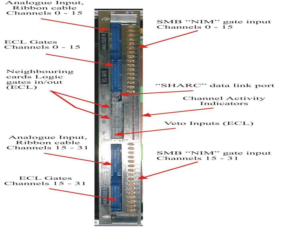
1 GREAT 32 channel peak sensing ADC module: User Manual Specification: 32 independent timestamped peak sensing, ADC channels. Input range 0 to +8V. Sliding scale correction. Peaking time greater than 1uS. Gate input Fast NIM, and Differential ECL. Timestamp derived from a 100Mhz 48 bit counter, synchronized to a Master counter present in the system timing co-ordinator, the VME based Metronome module. The timestamp is the time of the leading edge of the input Gate pulse. Analog Repeated 32 times. Gate from neighbours Analog Inspection Gate Gate width generation and selection logic 14 bit Peak sensing ADC channel. With sliding scale correction. Input PDS Gate from neighbours Data buffer Logic Inspection Eight Veto Inputs VETO to Channel routing LUT 100Mhz 48bit Timestamp. 32 Channel Readout via SHARC link to VME. 32 Channel and module control via VXI. SHARC Link 100Mhz Clock SYNC Reset Error VXI Interface Functional Block Diagram The block diagram above shows the functional layout of the module. There are 32 independent channels. Each channel comprises Gate selection and pulse width generation, an ADC channel card, and a data buffer. The channels are controlled and readout by common logic. Analog and Logic inspection lines allow the function of the channel to monitored.
2 The Gate selection and pulse width generation logic is used to route the input Gate signals from the front panel to the ADC. The ADC gate pulse width is determined by a slider on the MIDAS TDR32V control window. It is possible to route other front panel Gate inputs to generate the channels ADC gate in cases such as strip detector neighbour triggering. This is controlled by selecting the Channel Mode. For a more detailed explanation of the different modes see EDOC505. A Timestamp is stored at the leading edge of the Gate. The ADC channel converts at the end of the ADC gate signal. The ADC gate signal should be greater than 1uS wide for best results. The input voltage to the ADC card must be in the range 0 to 8V (8V approximately). It must be positive with respect to ground. The Peak detector will only operate with positive inputs and erroneous ADC codes will be generated should the peak happen to pull the input below ground. After conversion the ADC is readout, and reset. The data is stored in a buffer for transmission with the Timestamp to the Event Collator in a VME crate. The module will run with all 32 channels working with random data at 10K conversions per channel. Should the buffer become full, due to flow control, the entire module is inhibited. A scaler, Blocked Event Scaler, counts every Gate that is missed during this period. Each module has eight scalers which can be allocated to any of the 32 channels using the main window in MIDAS. User Interface in MIDAS. Controls for each channel : Enable/Disable. ADC gate pulse width, 50nS to 25.6uS. Gate Selection. Channel Mode: Disabled. Direct. Neighbour. Group 1 or More. Group only 1. Analog Inspection: Input to channel. PDS from ADC module. ( Peak Detect and Stretch ) Logic Inspection. There are a large number of options on this menu. Three signals provide the best information about the use of the channel. Front_panel_gate_input: Signal into the ADC Gate selection logic. ADC_Gate: Signal to the ADC. Select through the ADC submenu from the main Digital inspection line menu.


3 Gate_input_to_width_chip Signal within the logic indicates the channel Busy time. Select through the ADC sub-menu from the main Digital inspection line menu. ADC sub-menu Main Digital menu


4 Main card setup window. Launched by selecting TDR32V from the VXI module menu in the Base frame.


5 The ident attached to the ADC data, and the information sent with the full timestamp is stored here, in the Readout ident store.


6 The Engineering => electronics selection. The serial number, and modification number of the module are shown here. The Expert => setup window. This is used to monitor the status of the SYNC pulse synchronisation. The counter is enabled, and errors reset.
7
8
9
CMS Conference Report
 Available on CMS information server CMS CR 1997/017 CMS Conference Report 22 October 1997 Updated in 30 March 1998 Trigger synchronisation circuits in CMS J. Varela * 1, L. Berger 2, R. Nóbrega 3, A. Pierce
BABAR IFR TDC Board (ITB): requirements and system description
: requirements and system description") BABAR IFR TDC Board (ITB): requirements and system description Version 1.1 November 1997 G. Crosetti, S. Minutoli, E. Robutti I.N.F.N. Genova 1. Timing measurement with the IFR Accurate track reconstruction
BABAR IFR TDC Board (ITB): requirements and system description Version 1.1 November 1997 G. Crosetti, S. Minutoli, E. Robutti I.N.F.N. Genova 1. Timing measurement with the IFR Accurate track reconstruction
Slide 1. Flip-Flops. Cross-NOR SR flip-flop S R Q Q. hold reset set not used. Cross-NAND SR flip-flop S R Q Q. not used reset set hold 1 Q.
 Slide Flip-Flops Cross-NOR SR flip-flop Reset Set Cross-NAND SR flip-flop Reset Set S R reset set not used S R not used reset set 6.7 Digital ogic Slide 2 Clocked evel-triggered NAND SR Flip-Flop S R SR
BABAR IFR TDC Board (ITB): system design
: system design") BABAR IFR TDC Board (ITB): system design Version 1.1 12 december 1997 G. Crosetti, S. Minutoli, E. Robutti I.N.F.N. Genova 1. Introduction TDC readout of the IFR will be used during BABAR data taking to
BABAR IFR TDC Board (ITB): system design Version 1.1 12 december 1997 G. Crosetti, S. Minutoli, E. Robutti I.N.F.N. Genova 1. Introduction TDC readout of the IFR will be used during BABAR data taking to
Miniball electronics for Orsay
 Miball electronics for Orsay Nigel Warr and Iolanda Matea 1 st June 2014 1 Contents 1 Foreword 3 2 Overview 3 3 The DGF BUSY/SYNCH loop 4 4 The GFLT fan- 5 5 The DAQ dead and DAQ go 6 6 Generation of the
EECS145M 2000 Midterm #1 Page 1 Derenzo
 UNIVERSITY OF CALIFORNIA College of Engineering Electrical Engineering and Computer Sciences Department EECS 145M: Microcomputer Interfacing Laboratory Spring Midterm #1 (Closed book- calculators OK) Wednesday,
A FOUR GAIN READOUT INTEGRATED CIRCUIT : FRIC 96_1
 A FOUR GAIN READOUT INTEGRATED CIRCUIT : FRIC 96_1 J. M. Bussat 1, G. Bohner 1, O. Rossetto 2, D. Dzahini 2, J. Lecoq 1, J. Pouxe 2, J. Colas 1, (1) L. A. P. P. Annecy-le-vieux, France (2) I. S. N. Grenoble,
Update on DAQ for 12 GeV Hall C
 Update on DAQ for 12 GeV Hall C Brad Sawatzky Hall C Winter User Group Meeting Jan 20, 2017 SHMS/HMS Trigger/Electronics H. Fenker 2 SHMS / HMS Triggers SCIN = 3/4 hodoscope planes CER = Cerenkov(s) STOF
Trigger synchronization and phase coherent in high speed multi-channels data acquisition system
 White Paper Trigger synchronization and phase coherent in high speed multi-channels data acquisition system Synopsis Trigger synchronization and phase coherent acquisition over multiple Data Acquisition
DE2-115/FGPA README. 1. Running the DE2-115 for basic operation. 2. The code/project files. Project Files
 DE2-115/FGPA README For questions email: jeff.nicholls.63@gmail.com (do not hesitate!) This document serves the purpose of providing additional information to anyone interested in operating the DE2-115
Simple PICTIC Commands
 The Simple PICTIC Are you an amateur bit by the Time-Nut bug but can t afford a commercial time interval counter with sub nanosecond resolution and a GPIB interface? Did you find a universal counter on
Large Area, High Speed Photo-detectors Readout
 Large Area, High Speed Photo-detectors Readout Jean-Francois Genat + On behalf and with the help of Herve Grabas +, Samuel Meehan +, Eric Oberla +, Fukun Tang +, Gary Varner ++, and Henry Frisch + + University
Design and Implementation of an AHB VGA Peripheral
 Design and Implementation of an AHB VGA Peripheral 1 Module Overview Learn about VGA interface; Design and implement an AHB VGA peripheral; Program the peripheral using assembly; Lab Demonstration. System
The TRIGGER/CLOCK/SYNC Distribution for TJNAF 12 GeV Upgrade Experiments
 1 1 1 1 1 1 1 1 0 1 0 The TRIGGER/CLOCK/SYNC Distribution for TJNAF 1 GeV Upgrade Experiments William GU, et al. DAQ group and Fast Electronics group Thomas Jefferson National Accelerator Facility (TJNAF),
DEPARTMENT OF ELECTRICAL &ELECTRONICS ENGINEERING DIGITAL DESIGN
 DEPARTMENT OF ELECTRICAL &ELECTRONICS ENGINEERING DIGITAL DESIGN Assoc. Prof. Dr. Burak Kelleci Spring 2018 OUTLINE Synchronous Logic Circuits Latch Flip-Flop Timing Counters Shift Register Synchronous
... A COMPUTER SYSTEM FOR MULTIPARAMETER PULSE HEIGHT ANALYSIS AND CONTROL*
 I... A COMPUTER SYSTEM FOR MULTIPARAMETER PULSE HEIGHT ANALYSIS AND CONTROL* R. G. Friday and K. D. Mauro Stanford Linear Accelerator Center Stanford University, Stanford, California 94305 SLAC-PUB-995
Update on DAQ for 12 GeV Hall C. Brad Sawatzky
 Update on DAQ for 12 GeV Hall C Brad Sawatzky SHMS/HMS Trigger/Electronics H. Fenker 2 SHMS / HMS Triggers SCIN = 3/4 hodoscope planes CER = Cerenkov(s) STOF = S1 + S2 EL-Hi = SCIN + PSh_Hi EL-Lo = 2/3{SCIN,
Model CO4020 Quad 4-Input Logic Unit Operating and Service Manual
 Model CO4020 Quad 4Input Logic Unit Operating and Service Manual Printed in U.S.A. ORTEC Part No. 762000 1202 Manual Revision C Advanced Measurement Technology, Inc. a/k/a/ ORTEC, a subsidiary of AMETEK,
Agilent Parallel Bit Error Ratio Tester. System Setup Examples
 Agilent 81250 Parallel Bit Error Ratio Tester System Setup Examples S1 Important Notice This document contains propriety information that is protected by copyright. All rights are reserved. Neither the
A MISSILE INSTRUMENTATION ENCODER
 A MISSILE INSTRUMENTATION ENCODER Item Type text; Proceedings Authors CONN, RAYMOND; BREEDLOVE, PHILLIP Publisher International Foundation for Telemetering Journal International Telemetering Conference
Chapter 6. Flip-Flops and Simple Flip-Flop Applications
 Chapter 6 Flip-Flops and Simple Flip-Flop Applications Basic bistable element It is a circuit having two stable conditions (states). It can be used to store binary symbols. J. C. Huang, 2004 Digital Logic
PHOTOTUBE SCANNING SETUP AT THE UNIVERSITY OF MARYLAND. Doug Roberts U of Maryland, College Park
 PHOTOTUBE SCANNING SETUP AT THE UNIVERSITY OF MARYLAND Doug Roberts U of Maryland, College Park Overview We have developed a system for measuring and scanning phototubes for the FDIRC Based primarily on
Experiment 7: Bit Error Rate (BER) Measurement in the Noisy Channel
 Measurement in the Noisy Channel") Experiment 7: Bit Error Rate (BER) Measurement in the Noisy Channel Modified Dr Peter Vial March 2011 from Emona TIMS experiment ACHIEVEMENTS: ability to set up a digital communications system over a noisy,
Experiment 7: Bit Error Rate (BER) Measurement in the Noisy Channel Modified Dr Peter Vial March 2011 from Emona TIMS experiment ACHIEVEMENTS: ability to set up a digital communications system over a noisy,
Digital Delay / Pulse Generator DG535 Digital delay and pulse generator (4-channel)
") Digital Delay / Pulse Generator Digital delay and pulse generator (4-channel) Digital Delay/Pulse Generator Four independent delay channels Two fully defined pulse channels 5 ps delay resolution 50 ps
Digital Delay / Pulse Generator Digital delay and pulse generator (4-channel) Digital Delay/Pulse Generator Four independent delay channels Two fully defined pulse channels 5 ps delay resolution 50 ps
Installation of a DAQ System in Hall C
 Installation of a DAQ System in Hall C Cuore Collaboration Meeting Como, February 21 st - 23 rd 2007 S. Di Domizio A. Giachero M. Pallavicini S. Di Domizio Summary slide CUORE-like DAQ system installed
Optical Link Evaluation Board for the CSC Muon Trigger at CMS
 Optical Link Evaluation Board for the CSC Muon Trigger at CMS 04/04/2001 User s Manual Rice University, Houston, TX 77005 USA Abstract The main goal of the design was to evaluate a data link based on Texas
SuperB- DCH. Servizio Ele<ronico Laboratori FrascaA
 1 Outline 2 DCH FEE Constraints/Estimate & Main Blocks front- end main blocks Constraints & EsAmate Trigger rate (150 khz) Trigger/DAQ data format I/O BW Trigger Latency Minimum trigger spacing. Chamber
Decade Counters Mod-5 counter: Decade Counter:
 Decade Counters We can design a decade counter using cascade of mod-5 and mod-2 counters. Mod-2 counter is just a single flip-flop with the two stable states as 0 and 1. Mod-5 counter: A typical mod-5
RX40_V1_0 Measurement Report F.Faccio
 RX40_V1_0 Measurement Report F.Faccio This document follows the previous report An 80Mbit/s Optical Receiver for the CMS digital optical link, dating back to January 2000 and concerning the first prototype
Data Acquisition System for Segmented Reactor Antineutrino Detector
 Data Acquisition System for Segmented Reactor Antineutrino Detector Z. Hons a,b,*, J. Vlášek a,c,d a Joint Institute for Nuclear Research, Moscow Region, Dubna, Russian Federation b NPI Nuclear Physics
Modcan Touch Sequencer Manual
 Modcan Touch Sequencer Manual Normal 12V operation Only if +5V rail is available Screen Contrast Adjustment Remove big resistor if using with PSU with 5V rail Jumper TOP VEIW +5V (optional) +12V } GND
Latest Timing System Developments
 Latest Timing System Developments Jukka Pietarinen EPICS Collaboration Meeting Shanghai March 2008 25.4.2007 Register Map Changes (new register mapping) CompactPCI boards implement new register mapping
Texas Instruments TNETE2201 Ethernet Transceiver Circuit Analysis
 October 31, 2003 Texas Instruments TNETE2201 Ethernet Transceiver Circuit Analysis Table of Contents List of Figures...Page 1 Introduction...Page 4 Device Summary Sheet...Page 6 Top Level Diagram...Tab
Chapter 2. Digital Circuits
 Chapter 2. Digital Circuits Logic gates Flip-flops FF registers IC registers Data bus Encoders/Decoders Multiplexers Troubleshooting digital circuits Most contents of this chapter were covered in 88-217
DXP-xMAP General List-Mode Specification
 DXP-xMAP General List-Mode Specification The xmap processor can support a wide range of timing or mapping operations, including mapping with full MCA spectra, multiple SCA regions, and finally a variety
DAQ Systems in Hall A
 CODA Users Workshop Data Acquisition at Jefferson Lab Newport News June 7, 2004 DAQ Systems in Hall A Overview of Hall A Standard Equipment: HRS, Beamline,... Parity Experiments Third Arms: BigBite, RCS
Digital Systems Laboratory 3 Counters & Registers Time 4 hours
 Digital Systems Laboratory 3 Counters & Registers Time 4 hours Aim: To investigate the counters and registers constructed from flip-flops. Introduction: In the previous module, you have learnt D, S-R,
Local Trigger Electronics for the CMS Drift Tubes Muon Detector
 Amsterdam, 1 October 2003 Local Trigger Electronics for the CMS Drift Tubes Muon Detector Presented by R.Travaglini INFN-Bologna Italy CMS Drift Tubes Muon Detector CMS Barrel: 5 wheels Wheel : Azimuthal
2.6 Reset Design Strategy
 2.6 Reset esign Strategy Many design issues must be considered before choosing a reset strategy for an ASIC design, such as whether to use synchronous or asynchronous resets, will every flipflop receive
IQVDA00/01 Analog Video Distribution Amplifier with RollCall Control
 IQVDA00/01 Analog Video Distribution Amplifier with RollCall Control Table of Contents Module Description... 2 Rear Panel View... 2 Product Comparison... 3 Block Diagram... 3 Features... 3 Technical Profile...
PICOSECOND TIMING USING FAST ANALOG SAMPLING
 PICOSECOND TIMING USING FAST ANALOG SAMPLING H. Frisch, J-F Genat, F. Tang, EFI Chicago, Tuesday 6 th Nov 2007 INTRODUCTION In the context of picosecond timing, analog detector pulse sampling in the 10
BER MEASUREMENT IN THE NOISY CHANNEL
 BER MEASUREMENT IN THE NOISY CHANNEL PREPARATION... 2 overview... 2 the basic system... 3 a more detailed description... 4 theoretical predictions... 5 EXPERIMENT... 6 the ERROR COUNTING UTILITIES module...
DIGITAL ELECTRONICS MCQs
 DIGITAL ELECTRONICS MCQs 1. A 8-bit serial in / parallel out shift register contains the value 8, clock signal(s) will be required to shift the value completely out of the register. A. 1 B. 2 C. 4 D. 8
Model BE-64. talon 150 E. Arrow Highway, San Dimas, CA TECHNICAL DESCRIPTION. Bus Emulator/Word Generator
 TECHNICAL DESCRIPTION Model BE-64 Bus Emulator/Word Generator Manual Revision: December 19, 1997 Manual Part Number: BETD400 Instrument Part Number: BE-64 talon 150 E Arrow Highway, San Dimas, CA 91773
A dedicated data acquisition system for ion velocity measurements of laser produced plasmas
 A dedicated data acquisition system for ion velocity measurements of laser produced plasmas N Sreedhar, S Nigam, Y B S R Prasad, V K Senecha & C P Navathe Laser Plasma Division, Centre for Advanced Technology,
TIME RESOLVED XAS DATA COLLECTION WITH AN XIA DXP-4T SPECTROMETER
 TIME RESOLVED XAS DATA COLLECTION WITH AN XIA DXP-4T SPECTROMETER W.K. WARBURTON, B. HUBBARD & C. ZHOU X-ray strumentation Associates 2513 Charleston Road, STE 207, Mountain View, CA 94043 USA C. BOOTH
PCIe BASED TWO CHANNEL DATA ACQUISITION CARD
 PCIe BASED TWO CHANNEL DATA Specification: PARAMETER DESCRIPTION Number of channels Two (up to 4 Channels). Input Data Rate 200 Mbps per Channel. Input Signal Level LVDS. Inputs 00 Clock and Data. Clock
EASY-MCS. Multichannel Scaler. Profiling Counting Rates up to 150 MHz with 15 ppm Time Resolution.
 Multichannel Scaler Profiling Counting Rates up to 150 MHz with 15 ppm Time Resolution. The ideal solution for: Time-resolved single-photon counting Phosphorescence lifetime spectrometry Atmospheric and
Digital Fundamentals: A Systems Approach
 Digital Fundamentals: A Systems Approach Counters Chapter 8 A System: Digital Clock Digital Clock: Counter Logic Diagram Digital Clock: Hours Counter & Decoders Finite State Machines Moore machine: One
AN-822 APPLICATION NOTE
 APPLICATION NOTE One Technology Way P.O. Box 9106 Norwood, MA 02062-9106, U.S.A. Tel: 781.329.4700 Fax: 781.461.3113 www.analog.com Synchronization of Multiple AD9779 Txs by Steve Reine and Gina Colangelo
Generation and Measurement of Burst Digital Audio Signals with Audio Analyzer UPD
 Generation and Measurement of Burst Digital Audio Signals with Audio Analyzer UPD Application Note GA8_0L Klaus Schiffner, Tilman Betz, 7/97 Subject to change Product: Audio Analyzer UPD . Introduction
Novel Data Acquisition System for Silicon Tracking Detectors
 Novel Data Acquisition System for Silicon Tracking Detectors L. A. Wendland, K. Banzuzi, S. Czellar, A. Heikkinen, J. Härkönen, P. Johansson, V. Karimäki, T. Lampén, P. Luukka, P. Mehtälä, J. Niku, S.
Design of the Level-1 Global Calorimeter Trigger
 Design of the Level-1 Global Calorimeter Trigger For I reckon that the sufferings of this present time are not worthy to be compared with the glory which shall be revealed to us The epistle of Paul the
013-RD
 Engineering Note Topic: Product Affected: JAZ-PX Lamp Module Jaz Date Issued: 08/27/2010 Description The Jaz PX lamp is a pulsed, short arc xenon lamp for UV-VIS applications such as absorbance, bioreflectance,
The GANDALF 128-Channel Time-to-Digital Converter
 Available online at www.sciencedirect.com Physics Procedia 37 (212 ) 1827 1834 TIPP 211 - Technology and Instrumentation for Particle Physics 211 The GANDALF 128-Channel Time-to-Digital Converter M. Büchele,
Novel Digital Pileup Inspection Circuit for a Gamma Ray Spectroscopy System
 Journal of Nuclear and Particle Physics 2014, 4(2): 58-64 DOI: 10.5923/j.jnpp.20140402.02 Novel Digital Pileup Inspection Circuit for a Gamma Ray Spectroscopy System Onyemaechi N. Ofodile 1,*, Matthew
NI-DAQmx Device Considerations
 NI-DAQmx Device Considerations January 2008, 370738M-01 This help file contains information specific to analog output (AO) Series devices, C Series, B Series, E Series devices, digital I/O (DIO) devices,
Introduction. NAND Gate Latch. Digital Logic Design 1 FLIP-FLOP. Digital Logic Design 1
 2007 Introduction BK TP.HCM FLIP-FLOP So far we have seen Combinational Logic The output(s) depends only on the current values of the input variables Here we will look at Sequential Logic circuits The
R3B Si TRACKER CABLE TEST REPORT
 R3B Si TRACKER CABLE TEST REPORT Author: Mos Kogimtzis Date: 22/05/2012 Department: NPG, Technology Project: R3B Si Tracker Detector Customer: Internal 1. Scope The aim of the test described below is to
Filtration manager for automatic calculation of corrected differential pressure measurement in refuelling applications
 Page: of: 0 Filtration manager for automatic calculation of corrected differential pressure measurement in refuelling applications FAUDI Aviation Sensor GmbH, Scharnhorststraße 7 B, D-560 Stadtallendorf
MBI5050 Application Note
 MBI5050 Application Note Foreword In contrast to the conventional LED driver which uses an external PWM signal, MBI5050 uses the embedded PWM signal to control grayscale output and LED current, which makes
ECB DIGITAL ELECTRONICS PROJECT BASED LEARNING PROJECT REPORT ON 7 SEGMENT DIGITAL STOP WATCH USING DECODER
 ECB2212 - DIGITAL ELECTRONICS PROJECT BASED LEARNING PROJECT REPORT ON 7 SEGMENT DIGITAL STOP WATCH USING DECODER SUBMITTED BY ASHRAF HUSSAIN (160051601105) S SAMIULLAH (160051601059) CONTENTS >AIM >INTRODUCTION
Chapter 4: One-Shots, Counters, and Clocks
 Chapter 4: One-Shots, Counters, and Clocks I. The Monostable Multivibrator (One-Shot) The timing pulse is one of the most common elements of laboratory electronics. Pulses can control logical sequences
Lecture 14: Computer Peripherals
 Lecture 14: Computer Peripherals The last homework and lab for the course will involve using programmable logic to make interesting things happen on a computer monitor should be even more fun than the
Diamond detectors in the CMS BCM1F
 Diamond detectors in the CMS BCM1F DESY (Zeuthen) CARAT 2010 GSI, 13-15 December 2010 On behalf of the DESY BCM and CMS BRM groups 1 Outline: 1. Introduction to the CMS BRM 2. BCM1F: - Back-End Hardware
Workshop 4 (A): Telemetry and Data Acquisition
: Telemetry and Data Acquisition") Workshop 4 (A): Telemetry and Data Acquisition Mahidol University June 13, 2008 Paul Evenson University of Delaware Bartol Research Institute 1 Workshop Series Idea Introduce students to technical aspects
Workshop 4 (A): Telemetry and Data Acquisition Mahidol University June 13, 2008 Paul Evenson University of Delaware Bartol Research Institute 1 Workshop Series Idea Introduce students to technical aspects
MUSIC TRANSCRIBER. Overall System Description. Alessandro Yamhure 11/04/2005
 Roberto Carli 6.111 Project Proposal MUSIC TRANSCRIBER Overall System Description The aim of this digital system is to convert music played into the correct sheet music. We are basically implementing a
Hello and welcome to this presentation of the STM32L4 Analog-to-Digital Converter block. It will cover the main features of this block, which is used
 Hello and welcome to this presentation of the STM32L4 Analog-to-Digital Converter block. It will cover the main features of this block, which is used to convert the external analog voltage-like sensor
Hello, and welcome to this presentation of the STM32 system window watchdog. It will cover the main features of this peripheral used to detect
 Hello, and welcome to this presentation of the STM32 system window watchdog. It will cover the main features of this peripheral used to detect software faults. 1 The window watchdog is used to detect the
C Module Description
 IQMMX -Input Router & ASI Distribution Amplifier C Module Description The IQMMX is an ASI to 1 switch, distribution amplifier and transport stream switcher with up to 8 outputs in double width form or
Counter dan Register
 Counter dan Register Introduction Circuits for counting events are frequently used in computers and other digital systems. Since a counter circuit must remember its past states, it has to possess memory.
TTC Interface Module for ATLAS Read-Out Electronics: Final production version based on Xilinx FPGA devices
 Physics & Astronomy HEP Electronics TTC Interface Module for ATLAS Read-Out Electronics: Final production version based on Xilinx FPGA devices LECC 2004 Matthew Warren warren@hep.ucl.ac.uk Jon Butterworth,
CEDAR Series. To learn more about Ogden CEDAR series signal processing platform and modular products, please visit
 CEDAR Series The CEDAR platform has been designed to address the requirements of numerous signal processing modules. Easily-installed components simplify maintenance and upgrade. To learn more about Ogden
FRONT-END AND READ-OUT ELECTRONICS FOR THE NUMEN FPD
 FRONT-END AND READ-OUT ELECTRONICS FOR THE NUMEN FPD D. LO PRESTI D. BONANNO, F. LONGHITANO, D. BONGIOVANNI, S. REITO INFN- SEZIONE DI CATANIA D. Lo Presti, NUMEN2015 LNS, 1-2 December 2015 1 OVERVIEW
MAHARASHTRA STATE BOARD OF TECHNICAL EDUCATION (Autonomous) (ISO/IEC Certified) WINTER 2018 EXAMINATION MODEL ANSWER
 (ISO/IEC Certified) WINTER 2018 EXAMINATION MODEL ANSWER") Important Instructions to examiners: 1) The answers should be examined by key words and not as word-to-word as given in themodel answer scheme. 2) The model answer and the answer written by candidate may
Important Instructions to examiners: 1) The answers should be examined by key words and not as word-to-word as given in themodel answer scheme. 2) The model answer and the answer written by candidate may
To fully utilize Media 100 s genlocking capability, you ll need the following equipment connected to your system:
 B Genlock Setup Overview............................................. 602 Required Equipment................................ 602 Using the Genlock Setup Window....................... 603 Selecting the
ADF-2 Production Readiness Review
 ADF-2 Production Readiness Review Presented by D. Edmunds 11-FEB-2005 The ADF-2 circuit board is part of the new Run IIB Level 1 Calorimeter Trigger. The purpose of this note is to provide the ADF-2 Production
CONTROL OF THE LOW LEVEL RF SYSTEM OF THE LARGE HADRON COLLIDER
 10th ICALEPCS Int. Conf. on Accelerator & Large Expt. Physics Control Systems. Geneva, 10-14 Oct 2005, PO1.028-1 (2005) CONTROL OF THE LOW LEVEL RF SYSTEM OF THE LARGE HADRON COLLIDER A. Butterworth 1,
EBU INTERFACES FOR 625 LINE DIGITAL VIDEO SIGNALS AT THE 4:2:2 LEVEL OF CCIR RECOMMENDATION 601 CONTENTS
 EBU INTERFACES FOR 625 LINE DIGITAL VIDEO SIGNALS AT THE 4:2:2 LEVEL OF CCIR RECOMMENDATION 601 Tech. 3267 E Second edition January 1992 CONTENTS Introduction.......................................................
YEDITEPE UNIVERSITY DEPARTMENT OF COMPUTER ENGINEERING. EXPERIMENT VIII: FLIP-FLOPS, COUNTERS 2014 Fall
 YEDITEPE UNIVERSITY DEPARTMENT OF COMPUTER ENGINEERING EXPERIMENT VIII: FLIP-FLOPS, COUNTERS 2014 Fall Objective: - Dealing with the operation of simple sequential devices. Learning invalid condition in
Review of digital electronics. Storage units Sequential circuits Counters Shifters
 Review of digital electronics Storage units Sequential circuits ounters Shifters ounting in Binary A counter can form the same pattern of 0 s and 1 s with logic levels. The first stage in the counter represents
Major Differences Between the DT9847 Series Modules
 DT9847 Series Dynamic Signal Analyzer for USB With Low THD and Wide Dynamic Range The DT9847 Series are high-accuracy, dynamic signal acquisition modules designed for sound and vibration applications.
Chapter 6 Digital Circuit 6-5 Department of Mechanical Engineering
 MEMS1082 Chapter 6 Digital Circuit 6-5 General digital system D Flip-Flops, The D flip-flop is a modification of the clocked SR flip-flop. The D input goes directly into the S input and the complement
OPERATOR'S MANUAL MODEL 3371 CAMAC 8-INPUT TDC
 OPERATOR'S MANUAL MODEL 3371 CAMAC 8-INPUT TDC 1 Innovators in Instrumentation Corporate Headquarters 700 Chestnut Ridge Road Chestnut Ridge, NY 10977-6499 Tel: (914) 578-6013 Fax: (914) 578-5984 E-mail:
Registers and Counters
 Registers and Counters Clocked sequential circuit = F/Fs and combinational gates Register Group of flip-flops (share a common clock and capable of storing one bit of information) Consist of a group of
Quad ADC EV10AQ190A Synchronization of Multiple ADCs
 Synchronization of Multiple ADCs Application Note Applies to EV10AQ190A 1. Introduction This application note provides some recommendations for the correct synchronization of multiple EV10AQ190A Quad 10-bit
New GRABLINK Frame Grabbers
 New GRABLINK Frame Grabbers Full-Featured Base, High-quality Medium and video Full capture Camera boards Link Frame Grabbers GRABLINK Full Preliminary GRABLINK DualBase Preliminary GRABLINK Base GRABLINK
Synthesis Technology E102 Quad Temporal Shifter User Guide Version 1.0. Dec
 Synthesis Technology E102 Quad Temporal Shifter User Guide Version 1.0 Dec. 2014 www.synthtech.com/euro/e102 OVERVIEW The Synthesis Technology E102 is a digital implementation of the classic Analog Shift
What is sync? Why is sync important? How can sync signals be compromised within an A/V system?... 3
 Table of Contents What is sync?... 2 Why is sync important?... 2 How can sync signals be compromised within an A/V system?... 3 What is ADSP?... 3 What does ADSP technology do for sync signals?... 4 Which
11. Sequential Elements
 11. Sequential Elements Jacob Abraham Department of Electrical and Computer Engineering The University of Texas at Austin VLSI Design Fall 2017 October 11, 2017 ECE Department, University of Texas at Austin
Installation / Set-up of Autoread Camera System to DS1000/DS1200 Inserters
 Installation / Set-up of Autoread Camera System to DS1000/DS1200 Inserters Written By: Colin Langridge Issue: Draft Date: 03 rd July 2008 1 Date: 29 th July 2008 2 Date: 20 th August 2008 3 Date: 02 nd
Last time, we saw how latches can be used as memory in a circuit
 Flip-Flops Last time, we saw how latches can be used as memory in a circuit Latches introduce new problems: We need to know when to enable a latch We also need to quickly disable a latch In other words,
Universal Asynchronous Receiver- Transmitter (UART)
") Universal Asynchronous Receiver- Transmitter (UART) (UART) Block Diagram Four-Bit Bidirectional Shift Register Shift Register Counters Shift registers can form useful counters by recirculating a pattern
Universal Asynchronous Receiver- Transmitter (UART) (UART) Block Diagram Four-Bit Bidirectional Shift Register Shift Register Counters Shift registers can form useful counters by recirculating a pattern
Logic Analyzer Triggering Techniques to Capture Elusive Problems
 Logic Analyzer Triggering Techniques to Capture Elusive Problems Efficient Solutions to Elusive Problems For digital designers who need to verify and debug their product designs, logic analyzers provide
DT9837 Series. High Performance, USB Powered Modules for Sound & Vibration Analysis. Key Features:
 DT9837 Series High Performance, Powered Modules for Sound & Vibration Analysis The DT9837 Series high accuracy dynamic signal acquisition modules are ideal for portable noise, vibration, and acoustic measurements.
IQACO Changeover Switch
 IQACO Changeover Switch C Module Description The IQACO is a passive changeover switch with composite video presence detection. Both inputs are monitored for sync presence, sync amplitude and line standard.
Klystron Lifetime Management System
 Klystron Lifetime Management System Łukasz Butkowski Vladimir Vogel FLASH Seminar Outline 2 Introduction to KLM Protection and measurement functions Installation at Klystron test stand FPGA implementation
CLC011 Serial Digital Video Decoder
 CLC011 Serial Digital Video Decoder General Description National s Comlinear CLC011, Serial Digital Video Decoder, decodes and descrambles SMPTE 259M standard Serial Digital Video datastreams with serial
Model 5240 Digital to Analog Key Converter Data Pack
 Model 5240 Digital to Analog Key Converter Data Pack E NSEMBLE D E S I G N S Revision 2.1 SW v2.0 This data pack provides detailed installation, configuration and operation information for the 5240 Digital
psasic Timing Generator
 psasic Timing Generator Fukun Tang psasic Design Review July 1-2 2009 University of Chicago 1 Diagram of 40Gs/s Sampling Chip CLOCK (80MHz) IN(1:32) Timing Generator with 2 DLLs interleaved PD CP LF φ1