Support Frame STB Technical Instruction Manual
|
|
|
- Clinton Lambert
- 6 years ago
- Views:
Transcription

1 Support Frame STB Technical Instruction Manual
 if only one side of the formwork can be erected. Usually, it is not practical to tie through the forms.")
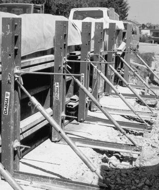
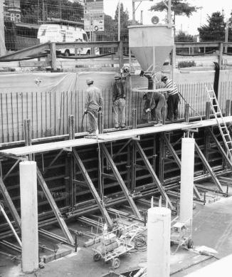
2 Fig. 2.1: Support frame STB 450 Fig. 2.2: Support frame STB 300 Fig. 2.3: Brace bracket SK 150 Product Characteristics The support frames are mainly used for pouring against existing structures (walls, rock, soil, sheet piling, foundations etc.) if only one side of the formwork can be erected. Usually, it is not practical to tie through the forms. Therefore, the total concrete pressure has to be transferred from the formwork via a support structure into the foundation. The MEVA support frames are painted steel structures. See LOAD CHART (separate book) for details about concrete pressure and anchor loads in standard applications. Safe working loads: When using the support frames the following points need to be looked at: - Foundations and floor slabs etc. must be able to resist the transmitted loads (a static calculation might be required). - The "opposite side" of the single-sided formwork (e.g.existing structure) must be able to resist the concrete pressure as well. - Anchors must be able to resist the transferred loads. - Anchors must not be welded, heated or deformed. - In case of more complicated or special cases not dealt with in this manual, please contact the MEVA experts for advice. Anchor Safe working load Attention: 5/8" Threadbars (DW 15) 21.9 kips (98 kn) 7/8" Threadbars (DW 20) 39.2 kips (174 kn) 1" Threadbars (DW 26.5) 63.7 kips (284 kn) To anchor the support frames into the supporting struc- ture always use two (2) anchors per frame!! On site it needs to be checked that the occurring tensile forces Z and the pressures V can be safely transferred into the foundation or floor slab. Especially the concrete strength and the kind of rebar used, need to be reviewed. If the support frames are used on top of slabs make sure to support the slab where the vertical forces occur, in order to transfer these into the foundation. June 2010 STB-2
3 Support Frame STB Please note: This technical manual contains information, instructions and hints describing how to use MEVA support frames on the construction site in a proper, quick and economic way. Most examples shown are standard applications, that will occur in practice most often. For more complicated or special applications not covered in this manual, please contact the MEVA experts for advice. When using our products the federal, state and local codes and regulations must be observed. Details shown on the following pages are assembly sketches for demonstration purposes only. To display details more clearly, loading and safety factor aspects are not shown. Please adhere to these technical instructions when applying the support frames. Deviations require engineering calculations and analysis to guarantee safety. Generally, only well maintained material may be used. Damaged parts must be sorted out. Apply only original MEVA spare parts for replacement. Contents STB 300 units... 4 STB 450 units... 5 Assembly of STB units... 6 Diagonal Bracing... 7 Working Platforms... 8 Anchoring... 9 Anchoring Details Anchoring Auxiliary Anchoring (step by step) Bulkheads Corner Bracket STB Crane Ganging Moving STB units with trolley Brace Bracket SK Transport Service Notes Product List APPENDIX Load Charts...A-2 - A-19 STB-3
.")
 any panel size can be used because the support frames are screwed (with flange screws 18) to the multi-function profiles of the Imperial panels.")

. The cross beam 300 (in horizontal position) is placed between formwork panel and support frame.")
4 STB 300 units STB 300 in combination with panels in horizontal position up to a height of 11'. The support frame 300 must be attached to StarTec formwork at tie holes by using fixing screws 35 and flange nuts 100 (Fig. 4.1, Fig. 4.2, Fig. 4.4 and Fig. 4.5). When using the Imperial system (Fig. 4.3) any panel size can be used because the support frames are screwed (with flange screws 18) to the multi-function profiles of the Imperial panels. Because of static and economical reasons we recommend to use the STB in combination with panels in horizontal position. Fig. 4.1: STB 300 with panels in horizontal position Fig. 4.2: StarTec formwork Fig. 4.3: Imperial formwork Attention: Before mounting the STB to the formwork panel, set spindle at middle position. Fig. 4.4: Detail: Fixing screw at the side of the STB Fig. 4.5: Detail: Fixing screw at the side of the facing STB 300 in combination with panels in vertical position by using the cross beam 300 (Fig. 4.6). The cross beam 300 (in horizontal position) is placed between formwork panel and support frame. The cross beam 300 allows to build units while the distance between the support frames is arbitrary. The cross beam 300 is designed to match the StarTec (Fig. 4.7) and Imperial (Fig. 4.8) formwork systems. Fig. 4.6: STB 300 with panels in vertical position Fig. 4.7: StarTec formwork Fig. 4.8: Imperial formwork STB-4
 flange screws per STB are recommended Fig. 5.")


 STB 450 plus three (3) height extensions 150, two (2) base extensions and two (2) Triplex heavy duty")
 STB 450 plus four (4) height extensions 150, three (3) base extensions and three (3) Triplex heavy duty")


5 Support Frame STB STB 450 units Fig. 5.1: STB 450 up to a height of 17'; three (3) flange screws per STB are recommended Fig. 5.2: STB 450 up to a height of 22'; four (4) flange screws per STB are recommended For a height up to 26' five (5) flange screws per STB are recommended to attach the formwork panels to the support frames and extensions (not illustrated). The STB 450 is designed for singlesided formwork up to a height of 17'(Fig. 5.1). By using a STB 450 support frame and an additional height extension 150 singlesided formwork up to a height of 22' can be erected (Fig. 5.2). One (1) STB 450 plus three (3) height extensions 150, two (2) base extensions and two (2) Triplex heavy duty braces are necessary to form a height of 31' (Fig. 5.3). One (1) STB 450 plus four (4) height extensions 150, three (3) base extensions and three (3) Triplex heavy duty braces allow for a height of 36' (Fig. 5.4). Attention: By using StarTec panels in horizontal position the fixing screw 35 in combination with a flange nut 100 has to be used to attach the panels to the support frame. To avoid an interference between the cross members of the support frame and the fixing screw we recommend to start with 135 cm wide panels. Fig. 5.3: STB 450 up to a height of 31'; six (6) flange srews per STB are recommended Fig. 5.4: STB 450 up to a height of 36'; seven (7) flange screws per STB are recommended When using the Imperial system any panel size can be used because the support frames are screwed (with flange screw 18) to the multi-function profiles of the Imperial panels. STB-5


6 Assembly of STB units Assembly area: The area where the formwork is pre-assembled should be clean, even and capable of taking the expected weight. The support frames are attached at the backside of the formwork panels. With the StarTec system fixing screws 35 and flange nuts 100 are needed for the connection (Fig. 6.1). With the Imperial system flange screws are required to connect panels and support frames. The pre-assembled unit should rest on square timbers (face down) on the ground before they are "flown" into place. Fig. 6.1 Assembly of the diagonal, heavy duty braces Triplex Depending on the overall height it might be required to attach Triplex braces to the height and base extensions. All the accessories for the connection (nuts, bolts and pins) come with the height and base extensions (Fig. 6.2, 6.3 and 6.4). Fig. 6.3 Fig. 6.4 Fig. 6.2 STB-6

 and swivel joint couplers are necessary.")
.")
 diagonal scaffold tube (Fig. 7.")

7 Support Frame STB Diagonal Bracing Fig. 7.1 Fig. 7.2 To build the required diagonal bracing, scaffold tubes ( 1.9") and swivel joint couplers are necessary. Units built out of STB 300 frames only, need one (1) horizontal tube (Fig. 7.1). Units built out of STB 450 frames need two (2) horizontal and one (1) diagonal scaffold tube (Fig. 7.2 and Fig. 7.3). If height extensions are used, one additional horizontal scaffold tube per height extension is required from the second height extension on (Fig. 7.4). Fig. 7.3 Fig. 7.4 STB-7


8 Working Platforms In general, the scaffolding brackets 90 and 125 in combination with the guardrailing posts can be used to build a working platform. The procedure is the same as it is with the two-sided wall formwork (Fig 8.1 and 8.2). For further details please see Technical Instruction Manual of the formwork system you are using. Surface related load, specified by OSHA: 25 psf (workers only, no material) Minimum platform width: 20" Fig. 8.1 Imperial Fig. 8.2 StarTec Attachment of boards at scaffolding bracket by using bolts with 3/8" and a minimum length of 4.5" When using the STB 450 support frame it is recommended to bolt planks or boards to the support frame or height extension (Fig 8.3 and 8.4). The holes which are used for the attachment of height extensions can be used. The support frames 450 and the height extensions 150 provide pockets for sliding in the guard railing posts. Attention: When using our products the federal, state and local codes and regulations must be observed. Description Ref.-No. Fig. 8.3 Imperial Fig. 8.4 StarTec Scaffolding bracket Scaffolding bracket Guard-railing post Guard-railing post Attachment of boards at support frames or extensions by using bolts with 13/16" and a minimum length of 2.75" STB-8
9 Support Frame STB Anchoring Depending on the load, there are different possibilities to anchor the support frames. - Anchor loop in combination with the cross stiffener 44 (Fig. 9.1 and Detail). Fig. 9.1 Fig Anchor loop in turned configuration; if support frame sits on top of a slab (Fig. 9.2). It needs to be discussed with the stress analysts, if additional rebar is required. - Anchoring by using a 1" (26.5 mm) threadbar and a twin channel 80 or 245 (Fig. 9.3). Detail: Anchor loop Description Ref.-No. Fig. 9.3 Cross stiffener Twin channel Twin channel STB-9
10 Anchoring Details STB 300 and panels in horizontal position (Fig and 10.2). 10" Fig STB 300 and panels in vertical position, e.g. for corner solutions (Fig and 10.4). When using the STB 300 support frame we recommend anchor loops. If the corner bracket is used we recommend using single threadbars in the corner area. 10" 10" 7" Fig " 10" Fig " Fig " STB-10
. The amount and kind (5/8\", 7/8\", 1\") of threadbars needed can be determined in the LOAD CHART. Fig. 11.3 12\" 20\" 12\" Fig. 11.4 20\" STB-11")
11 Support Frame STB Anchoring Details STB 450 and panels in horizontal position (Fig and 11.2). 8" 20" 8" 20" Fig Fig STB 450 and panels in vertical position, e.g. for corner solutions (Fig and 11.4). The amount and kind (5/8", 7/8", 1") of threadbars needed can be determined in the LOAD CHART. Fig " 20" 12" Fig " STB-11

12 Anchoring Auxiliary The anchoring auxiliary STB facilitates the installing of threadbars into the foundation. The auxiliaries are attached to the rebar and guarantee an angle of 45. The threadbar can be slid through the auxiliary at any position which allows adapting to any foundation size. The plastic sleeve (with a thread for 1" threadbars) keeps the threadbar at the ideal position. 2" Fig " 12" Coupling nut Packing units: Anchoring auxiliary 15 STB: One unit contains 50 pieces. Anchoring auxiliary 20 and 26.5 STB: One unit contains 40 pieces. Anchoring auxiliary Plastic sleeve Threadbar The plastic sleeves are included in the delivery. Fig Wall formwork Twin channel 245 Threadbar Support frame STB 450 Description Ref.-No. Anchoring auxiliary 15 (5/8") Anchoring auxiliary 20 (7/8") Anchoring auxiliary 26.5 (1") Coupling nut 15 (SW 30) Coupling nut 20 (SW 36) Coupling nut 26.5 (SW 48) Fig Coupling nut Anchoring auxiliary Threadbar Counter plate Hexagonal nut STB-12
13 Support Frame STB Anchoring (step by step) Anchor loop 5/8" (15 mm) Fig Fig Step 1: Installing of anchor loop 5/8" by using the anchoring auxiliary (Fig and 13.2), which can be attached to the rebar. Observe required concrete cover! Step 2: Screw coupling nut 5/8"(15 mm) on threadbar (Fig. 13.3), and then both on anchor loop (Fig. 13.4). Fig Fig Threadbar 7/8" (20 mm) and 1" (26.5 mm) Step 1: Attach counter plate and hexagonal nut to threadbar. Step 2: Installing of threadbars by using the anchoring auxiliary (Fig and 13.6), which can be attached to the rebar. Fig Fig Observe required concrete cover! Step 3: Screw coupling nut on (extension) threadbar (Fig. 13.7), and then both on (casted in) threadbar (Fig. 13.8). Fig Fig STB-13

14 Bulkheads The Bulkhead bracket SB 110 is attached to the formwork panels by using 5/8" threadbars (Ref.-No.: ) and flange nuts 100 (Ref.-No.: ). The adjustment range of the bulkhead bracket is 3'. Wall thicknesses up to 3' are possible. Fig Threadbar through support frame Imperial panel in horizontal position Flange nut 100 Threadbar in Dywidag threaded nut Support frame STB 450 Bulkhead bracket Fig Fig Clamping device for bulkhead bracket through support frame ST-panel 270 in horizontal position Flange nut 100 Threadbar in Dywidag threaded nut Support frame STB 450 Description Ref.-No. Bulkhead bracket SB Clamping device for bulkhead bracket SB Bulkhead bracket Fig STB-14


 bulkhead brackets are")
 bulkhead brackets are required for a height")
 bulkhead brackets are required for a height")
15 Support Frame STB Bulkheads The Bulkhead bracket SB 110 is attached to the formwork panels by using 5/8" threadbars and flange nuts 100 (Fig to 15.4). The support frame is between bulkhead bracket and formwork panel. The threadbar 5/8" should be 18" long and is screwed into the Dywidag - threaded nuts of the formwork panels. Fig Two (2) bulkhead brackets are required for a height up to 11' Fig Three (3) bulkhead brackets are required for a height up to 17' Six (6) bulkhead brackets are required for a height up to 31'. Seven (7) bulkhead brackets are required for a height up to 36'. Fig Four (4) bulkhead brackets are required for a height up to 22' Fig Five (5) bulkhead brackets are required for a height up to 26' Description Ref.-No. Bulkhead bracket SB Clamping device for bulkhead bracket SB STB-15

 for panels with steel rails. A maximum formwork height of 9' 10\" (3.00 m) is possible when using StarTec and STB 300.")

16 Corner Bracket STB Single-sided corner areas can be formed by using the corner bracket STB. The corner bracket STB has to be attached to the multi-function profiles by using flange screws 18. STB 300 For detailed dimensions for position of anchors see Fig and Fig For anchoring of STB brackets see also pages When using the StarTec formwork system make sure to use panels in vertical position (Fig. 16.1). To support joint between "corner" panel and adjacent panel use horizontal steel rails. Be aware to set back anchors (4") for panels with steel rails. A maximum formwork height of 9' 10" (3.00 m) is possible when using StarTec and STB 300. When using the Imperial formwork system you should use a "corner" panel which is in vertical position and continue to use the large size gangs as usual (Fig. 16.2). The minimum width of the "corner" panel is 2'-0", the maximum width is 2'-6". In this configuration no horizontal steel rails are required. A maximum formwork height of 10' 0" (3.05 m) is possible when using Imperial and STB 300. Attention: Dimensions for anchor positions have to be observed. Fig STB 300 in combination with Star Tec Height: 8'-10" (2.70 m) max. 8' Min.: 2'-0" Max.: 2'-6" Fig Fig " 2.75' 2.8' 9" 6.7" 9" 9" 6.7" 9" 16.34" 2.6' 2.8' Description Ref.-No. Corner bracket STB Fig STB 300 in combination with Imperial Height: 10'-0" STB-16


.")
 for panels with steel rails.")
.")

17 Support Frame STB Corner Bracket STB max. 8' 2.85' 17.13" The corner bracket STB has to be attached to the multi-function profiles by using flange screws 18. Fig STB 450 in combination with Star Tec Height: 17'-9" (5.40 m) Min.: 2'-0" Max.: 2'-6" 17.13" 2.87' Fig Fig ' 2.1' 2.87' STB 450 For detailed dimensions for position of anchors see Fig and Fig For anchoring of STB brackets see also pages When using the StarTec formwork system make sure to use panels in vertical position (Fig 17.1). To support joint between "corner" panel and adjacent panel use horizontal steel rails. Be aware to set back anchors (4") for panels with steel rails. When using the Imperial formwork system you should use a "corner" panel which is in vertical position and continue to use the large size gangs as usual (Fig. 17.2). The minimum width of the "corner" panel is 2'-0", the maximum width is 2'-6". In this configuration no horizontal steel rails are required. Attention: Dimensions for anchor positions have to be observed. Make sure that inside corner and "corner" panel are absolutely flush when installing them. Fig STB 450 in combination with Imperial Height: 20'-0" Description Ref.-No. Corner bracket STB STB-17


18 Crane Ganging Units with the STB 300 are moved by using the crane hook of the wall-formwork system which is used (Fig Fig. 18.2). Watch capacity of crane hooks. When flying units with the STB 450, crane slings should be used (Fig and Fig. 18.4). The STB 450 and the extension 150 are equipped with crane eyes. For proper assembly of STB units please see pages 4-7. Attention: Do not strip STB units by breaking them free from the concrete by crane! When setting STB units down to the ground make sure that units do not tilt over. If necessary use counter weight. Fig STB 300 with Imperial Fig STB 300 with StarTec Fig STB 450 with Imperial Fig STB 450 with Imperial (12' panels) STB-18


. To move the whole unit a counter weight is necessary to avoid tilting over.")
 are required.")

19 Support Frame STB Moving STB units with trolley Fig Fig By using the trolley waler, STB units can be easily and quickly moved around on the job if a crane is not available, e.g. in tunnels. The trolley waler can be mounted both to the STB 300 and to the STB 450. Assembly of trolley waler The trolley waler is bolted to the support frames (counter plates and nuts are already attached to the waler). To move the whole unit a counter weight is necessary to avoid tilting over. To build one unit two trolley walers, four wheel adapters and four trolley spindles are needed. Depending on the weight, four swivel type castors (2 tons or 6 tons) are required. The wheels are mounted to the waler by raising the unit. To raise the unit the trolley spindles come into play. The weight of the counter weight is depending on the height of the formwork and the kind of support frame. Attention: The support frames must not stand on trolley spindles while pouring. When using the STB 300 make sure to remove the trolley waler adjacent to the panels; otherwise anchoring is not possible. Fig Fig Description Ref.-No. Trolley waler Trolley waler Wheel adapter Spindle 48/ Swivel type castor 2 ton ton STB-19
.")

20 Brace Bracket SK 150 The brace bracket SK 150 is used to form bulkheads of slabs or foundations, even on sloped surfaces (Fig and 20.2). Adjustment range: SRL 120 = SRL 170 = Brace bracket SK 150 Brace SRL 120 Fig Brace bracket SK 150 Brace SRL 170 Description Ref.-No. Brace bracket SK Brace SRL Brace SRL Fig STB-20
 Base seal 4'-11\" (150 cm) Support for power screed Imperial 8' x 2.5' Brace bracket SK 150 - max. distance = 4'-7\" (concrete pressure max.")
 Typical application: Foundation slab with joint tape The positioning support SK allows for exact leveling and positioning of the bulkhead, even on sloped surfaces.")
21 Support Frame STB Brace Bracket SK 150 Joint seal Insulation alkus-facing Concrete pressure max. 400 psf Inner joint-tape (Waterstop) Base seal 4'-11" (150 cm) Support for power screed Imperial 8' x 2.5' Brace bracket SK max. distance = 4'-7" (concrete pressure max. 400 psf) Positioning support SK Wood spacer, depending on width of joint Brace SRL 120 (170) min. 6" (15 cm) Typical application: Foundation slab with joint tape The positioning support SK allows for exact leveling and positioning of the bulkhead, even on sloped surfaces. The brace bracket can be easily attached to the Dywidag threaded nuts of formwork panels (Imperial and StarTec). The braces SRL 120 or 170 and the positioning support SK have to be ordered separately. 4 Fi scher anchors FZA 18 or similar Fig Description Ref.-No. Positioning support SK Brace bracket SK Brace SRL Brace SRL STB-21


. Fig. 22.")
 support frames can be")
22 Transport Brace bracket SK 150 To transport brace brackets use MEVA piling racks. One rack takes 25 brackets, folded without braces (Fig. 22.1). Support frame STB 300 Ten (10) support frames can be stacked. To facilitate stacking the frames are equipped with a welded-on stacking device (Fig and 22.3). Fig Support frame STB 450 Four (4) support frames can be stacked. To facilitate stacking the frames are equipped with a welded-on stacking device (Fig and 22.5). Fig Fig Fig Fig STB-22


 Fig. 23.")

23 Support Frame STB Transport Loading of trucks Support frame STB x 10 = 60 frames (Fig and 23.2) Support frame STB x 4 = 12 frames (Fig and 23.4) Fig Fig Fig Fig STB-23


24 Service Rentals We offer our customers the option of renting supplementary material during peak times. We also give prospective customers the chance to test MEVA formwork so they can see its benefits for themselves in actual use. RentalPlus Since MEVA started the flat rate for cleaning and repair of rented formwork systems in early 2000 more and more contractors experience the outstanding advantages. Ask our representatives about the details! Formwork drawings Of course, all offices in our technical department have CAD facilities. You get expert, clearly represented plans and work cycle drawings. Special solutions We can help with special parts, custom- designed for your project, as a supplement to our formwork systems. Static calculations Generally, this is only necessary for applications like single-sided formwork where the anchor parts are embedded in the foundation or the base slab. If requested, we can perform static calculations for such applications at an additional charge. MBS - MEVA Basic Support MBS is an addition to AutoCAD, developed by MEVA Formwork Systems in MBS is based on standard programs (Auto CAD and Excel) and can be used on any PC that has these two programs installed. It includes pull down menues for AutoCAD and applications to ease forming. It also includes the possibility to create take-offs. STB-24
25 Support Frame STB Notes STB-25
26 Notes STB-26
Support Frame STB Assembly and Operating Instructions
 Support Frame STB Assembly and Operating Instructions Fig. 2.1 Support frame STB 450 Fig. 2.2 Support frame STB 300 Fig. 2.3 Brace bracket SK 150 Product features The support frames are mainly used for
19" TiRAX cabinet system. from page 3. 19" NETcell cabinet system from page 31. Open 19" racks from page 43
 19" TiRAX cabinet system from page 3 19" NETcell cabinet system from page 31 Open 19" racks from page 43 all-mounting/stand-alone distribution systems from page 53 all-mounting enclosure systems from page
1.0 DESCRIPTION. This specification covers roll-up signs to be used in temporary traffic control zones.
 (Page 1 of 10) ROLL-UP SIGNS (MGS-04-01O) 1.0 DESCRIPTION. This specification covers roll-up signs to be used in temporary traffic control zones. 2.0 MATERIAL. 2.1 SIGNS AND OVERLAYS. 2.1.1 SUBSTRATES.
CONTACT-DUO-PROFILE. Contact-Duo-Profile overview
 13 6.3 13 6.3 4.7 20.7 24.6 +1/-0 24.6 +1/-0 2.5 24.6 +1/-0 20.7 4.3 +0.3-0.4 3.6 ±0.3 32.5 32.5 32.5 5 2 CONTACT-DUO-PROFILE Contact-Duo-Profile overview 13 6.3 13 6.3 4.7 2.5 16±0.8 4.7 2.5 4.7 2.5 2.6
Cable installation guidelines
 The Quality Connection Cable installation guidelines Business Unit Industrial Projects 2 Cable installation guidelines www.leoni-industrial-projects.com GENERAL Installation methods Many different methods
In-Ceiling Electric Motorized Front Projection Screen Evanesce Series. User s Guide
 In-Ceiling Electric Motorized Front Projection Screen Evanesce Series User s Guide Important Safety & Warning Precautions Make sure to read this user s guide and follow the procedures below. Caution: The
ACADEMIC SUCCESS CENTER THE COLLEGE AT BROCKPORT STATE UNIVERSITY OF NEW YORK PROJECT NO
 SECTION 270536 - CABLE TRAYS FOR COMMUNICATIONS SYSTEMS PART 1 - GENERAL 1.1 RELATED DOCUMENTS A. Drawings and general provisions of the Contract, including General and Supplementary Conditions and Division
THE CABLE TRAY SYSTEM
 C A B L E S A N I T A T I O N C A B L E T R A Y S Y S T E M S THE CABLE TRAY SYSTEM The SILTEC cable tray system is a product, developed for optimum functionality and with focus on simplicity and accessibility,
Check what you have received against the component checklist and hardware above.
 SA46S SA46W SA46B SA46PB Component Checklist Installation Instructions SYSTEMA Systema Monitor Arm 460mm HARDWARE Display Mounting Spacers (x4) Display Mounting Screws Arm Assembly VESA monitor head M4
SPECIFICATION FIBER OPTIC SPLICE CLOSURE. Spec No : VSS-1007-BS403A-04A/SD. VSS-0107-BS403A-04A/SD R & D Center Manufacturing Division
 SPECIFICATION FIBER OPTIC SPLICE CLOSURE Model Spec. No. Distribution Depts. VSOF-BS403A VSS-0107-BS403A-04A/SD R & D Center Manufacturing Division Sales Division Management Division Revision 10. 07 (Rev.4)
Growmaster Assembly Instructions
 Growmaster ssembly Instructions Item No. Part Sect. Ref. Size mm Quantity Item No. Part Sect. Ref. Size mm Quantity 1001 15 M6 x 12 86x 97x 108x 1067 6 295 16 M6 9 10 113x 1301 7 30 9x 1 13x 5 7 3.5 x
HCS - HES Cabling Systems
 HCS - HES Cabling Systems Installation Manual for HCS High-Capacity Fiber-Optic Rack-Mount Cabinets Be sure to read and completely understand this procedure before applying product. Be sure to select the
Installation Guide OvalSox TM Cable
 Installation Guide OvalSox TM Cable Thank you for selecting a DuctSox System. This guide will be helpful for the installation of an OvalSox Cable System. Sections of fabric will be labeled, assembled,
Site Installation Model MP-8433
 Site Installation Model MP- Rev. //0 SCOREBOARD SITE INSTALLATION INSTRUCTIONS CAUTION: All American Scoreboards (AAS) recommends the sign be installed by a licensed contractor, and must meet all local
FREE STANDING CABINETS - S SERIES
 w w w. t e c h l o g i k s. c o m Techlogiks Canada Inc. - S SERIES Techlogiks S-Series Free Standing Cabinets has an available height ranging from 2U to 7U with a width of mm, mm and depth of mm, mm and
3 Cleaning. 4 Technical data
 EXC+ EXC- Sig- SIG+ SEN- SEN+ 2.4 Attaching cable to the analog board Attaching cable of the weighing cell to the system solution Connect the cable to the appropriate terminal strip of the Ex1 system solution
Site Installation Model MP-8424
 Site Installation Model MP- Rev. //0 SCOREBOARD SITE INSTALLATION INSTRUCTIONS CAUTION: All American Scoreboards (AAS) recommends the sign be installed by a licensed contractor, and must meet all local
RACKS, ENCLOSURES AND CABLE MANAGEMENT
 and RS3 RACK SYSTEM (pages 6.2 6.3) RS RACK SYSTEM (pages 6.4 6.5) EXTENDED DEPTH RS RACK SYSTEM (page 6.5) Vertical Side Rail Capacity Cable Manager Covers Accessories 117mm x 152mm (4.6 in. x 6.0 in.)
INSTRUCTION MANUAL [J] [E] [C] [G] [B] [I] [H] [D] [F] [A] 0 INTRODUCTION 1 RECOMMENDATIONS 2 ACCESSORIES INCLUDED
![INSTRUCTION MANUAL [J] [E] [C] [G] [B] [I] [H] [D] [F] [A] 0 INTRODUCTION 1 RECOMMENDATIONS 2 ACCESSORIES INCLUDED](/thumbs/87/97107658.jpg "INSTRUCTION MANUAL [J] [E] [C] [G] [B] [I] [H] [D] [F] [A] 0 INTRODUCTION 1 RECOMMENDATIONS 2 ACCESSORIES INCLUDED") 0 INTRODUCTION Video Lift is an electro-mechanical device which, once installed in the ceiling, allows vertical movement (ceiling floor ceiling) for loads of up to 19 Kg and with maximum runs of 1 metre
0 INTRODUCTION Video Lift is an electro-mechanical device which, once installed in the ceiling, allows vertical movement (ceiling floor ceiling) for loads of up to 19 Kg and with maximum runs of 1 metre
Up to 85% higher Service Life due to efficient sealing method.
 Robot Accessories Feeding through Up to 85% higher Service Life due to efficient sealing method. 346 Robot Accessories Feeding through Feeding through DDF 2 Rotary Feed-through Series Size Page DDF 2 348
UltraTwist. Product Description. Instruction Guide
 UltraTwist Instruction Guide English 7EN111103-01 2009-07-06 Applies to the following models: UltraTwist Slim Prod. No. 3126045 UltraTwist Wide Prod. No. 3126047 UltraTwist Slim UltraTwist Wide Product
QC Electromagnetic Overhead Crane Specifications
 YUANTAI CRANE QC Electromagnetic Overhead Crane Specifications Compact structure, new style, beautiful outlooking Good in usability with long service life Bearing high capacity, high working class Flexible
Fully ly Automaticti. Motorised Satellite t TV System. User s manual REV
 REV. 1.0 Fully ly Automaticti Motorised Satellite t TV System User s manual Customer Help Line: 1300 139 255 Support Email: support@satkingpromax.com.au Website: www.satkingpromax.com.au www.satkingpromax.com.au
Channel Cable Tray - Accessories
 Splice Plate The Splice Plate has the standard 4-hole pattern for all cable channel. Provided with straight sections and fittings. 9(*)-1043 3 (76) 9(*)-1044 4 (101) 9(*)-1044-6 6 (152) Horizontal Adjustable
ORION 60 lamp CEILING version
 Rev.3 Pag. 1 a 6 ORION 60 Ref LC102LRB TECHNICAL DATA Performances at 1mt distance ORION 60 Light intensity at 1m (Ec) 160klx Color temperature (K) 4500 / 5000 Color rendering index (CRI) 96 Luminous source
Safety Rules Parts Check Lists and Photos Cable Diagrams for Various Crane Configurations Step by Step Instructions Tips for Packaging and Storage
 EZ CRANE USER MANUAL INCLUDED INSIDE Safety Rules Parts Check Lists and Photos Cable Diagrams for Various Crane Configurations Step by Step Instructions Tips for Packaging and Storage WATCH THE INSTRUCTIONAL
Open Frame Racks and Accessories
 12.1 Open Frame Racks and Accessories 12 Table of Contents Open Frame Racks and Accessories Page No. Introduction 12.2 Open Frame Rack Kits & Accessories 12.3 12.4 Copper Rack Kit 12.3 Fiber Rack Kit 12.3
Identification - electrical services
 Identification - electrical services Aesthetic All live phase cable sheathing to be brown coloured and neutral phase cable sheathing to be blue coloured, all labelled L1, L2, L3 & N respectively in accordance
Installation Manual IPT Installation of skillet systems with 125 A track current. MV a-E.
 www.wampfler.com Page 1 of 27 Index Page 1 Basics...4 2 Basic understanding of an IPT -system...5 3 General rules regarding metal parts in close proximity...6 3.1 Envelope free of ferromagnetic material...6
TECHNICAL SPECIFICATION
 TECHNICAL SPECIFICATION (FIBER OPTIC SPLICE CLOSURE) Model Spec. No. Distribution Depts. VSOF-BS403A SJP-0609-403A-01A/SD Quality Assurance Team Manufacturing Division Sales Division Management Division
CENTRIFAN IN-LINE CENTRIFUGAL FAN
 CENTRIFAN IN-LINE CENTRIFUGAL FAN The Peerless Electric Centrifan represents the latest development in the fan and blower industry. Incorporating the tried and proven, highly efficient Peerless wheel in
Guide for installers. METTLER TOLEDO MultiRange System solution analog Ex1. Hazardous area. Safe area
 Guide for installers METTLER TOLEDO MultiRange System solution analog Ex1 Hazardous area Safe area System solution analog Ex1 Contents Contents Page 1 Safety precautions... 2 2 System overview... 3 2.1
Fiber Optic Splice Closure GPJ Instruction Manual
 Fiber Optic Splice Closure GPJ09-9401 Instruction Manual 1. Brief Introduction GPJ09-9401 type of Fiber Optic Splice Closure is a member in dome series, the main function is to provice direct pass, branch
Accessories for GF and RA machines
 Accessories for GF and RA machines A BRAND OF ITW ORBITAL CUTTING & WELDING 21 Orbital cutting & beveling machines for high-purity process piping Accessories for GF and RA machines Saw blade lubricant
Protective function Systems, cable, selectivity and generator protection. i 2 t constant function: switchable. I r A
 DATASHEET - NZMN3-VE630 Circuit-breaker, 3p, 630A Part no. NZMN3-VE630 Catalog No. 259133 EL-Nummer (Norway) 0004358791 Similar to illustration Delivery program Product range Circuit-breaker Protective
Everything under control
 FLYER UK 3-2018 01.07.2018 30.09.2018 WELDING TABLES AND CLAMPING SYSTEMS Everything under control THE SIEGMUND TABLE REDEFINED SUB TABLE BOX YOUR TOOLS ALWAYS AT HAND Create storage space under your welding
FIST-GCOG2-Dx6. Follow all local safety regulations related to optical fiber plant elements.
 FIST-GCOG2 I N S T A L L A T I O N I N S T R U C T I O N TC-986-IP Rev A, Mar 2017 www.commscope.com FIST-GCOG2-Dx6 Content 1 Introduction 2 General 2.1 Abbreviations 2.2 Kit contents 2.3 Tools 2.4 Accessories
I r A Protection against direct contact Finger and back of hand proof to VDE 0106 Part 100
 DATASHEET - NZMH2-A100 Circuit-breaker, 3p, 100A Part no. NZMH2-A100 Catalog No. 259099 Similar to illustration Delivery program Product range Circuit-breaker Protective function System and cable protection
NC-1000 INSTALLATION MANUAL NC-1000 FIBRE OPTIC CROSS-CONNECTION SYSTEM
 NC-1000 INSTALLATION MANUAL NC-1000 FIBRE OPTIC CROSS-CONNECTION SYSTEM Content 1. General 5 2. The products of NC-1000 system 6 3. Mounting of the frame 8 4. Earthing of the frame 8 NC-1000 FIBRE OPTIC
IndyGo Facility Upgrades Project 35671EE
 SECTION 260553 IDENTIFICATION FOR ELECTRICAL SYSTEMS PART 1 - GENERAL 1.1 SUMMARY A. Section Includes: 1. Identification for raceways. 2. Identification of power and control cables. 3. Identification for
The Zehnder LST brings a safe, attractive heating solution to applications where hot radiant surfaces are undesirable.
 zehnder LST The Zehnder LST brings a safe, attractive heating solution to applications where hot radiant surfaces are undesirable. The high quality, robust casing and slim lines ensure the Zehnder LST
SCREEN WINCH SYSTEM INSTALLATION MANUAL FOR SCREENS UP TO 300 cm. of width
 SCREEN WINCH SYSTEM INSTALLATION MANUAL FOR SCREENS UP TO 300 cm. of width Before installing the screen winch system, please read the following instructions carefully: The screen winch system must be used
H1000 Stay Cable System. The small size cable designed for durability according to fib, Setra and PTI recommendations
 H1000 Stay Cable System The small size cable designed for durability according to fib, Setra and PTI recommendations H1000 Stay Cable System Freyssinet H1000 stay cable is a parallel strand system for
SPECIFICATION FOR FIBER OPTIC SPLICE CLOSURE
 SP-CTN-CT3000M,CT3000ML-00 ISSUED : 2015/02/11 PAGE : 8 SPECIFICATION FOR FIBER OPTIC SPLICE CLOSURE CT3000M/CT3000ML Fiber Optic Splice Closure 2 / 8 1. GENERAL This specification covers the standards
SPECIFICATION. Spec No : VSS-1402-CS603B
 SPECIFICATION Spec No : VSS-1402-CS603B 1. INTRODUCTION 1.1. General This specification covers the design requirements and characteristics required of fiber optic splice closures to be used on fiber optic
VM GATE VALVE GRINDING & LAPPING MACHINE
 VM1150-1200 GATE VALVE GRINDING & LAPPING MACHINE 2014 04 VM1150-1200 Lightweight for easy handling and installation. Powerful Wide working range: nominal diameter of 1.5-48 inches (40-1200 mm). Submersion
All-Glass Sliding-System SF20
 Profile system All-glass sliding system Bottom loaded/running construction Option of flush or weathered bottom track The flush bottom track is particularly suitable for use in barrier-free dwellings according
SCREEN WINCH SYSTEM INSTALLATION MANUAL FOR SCREENS FROM 300 cm. UP TO 450 cm. of width
 SCREEN WINCH SYSTEM INSTALLATION MANUAL FOR SCREENS FROM 300 cm. UP TO 450 cm. of width Before installing the screen winch system, please read the following instructions carefully: The screen winch system
High Resolution Concrete Imaging
 High Resolution Concrete Imaging Quick Start Guide Field Operations Introduction 3 Section 1: Hardware Assembly & Startup System 4 Section 2: Parameter Settings 5 Section 3: Distance Calibration 6 Section
1.8 METER SERIES 1183 Az/El MOUNT ANTENNA SYSTEM
 REVISION G January 11, 2002 ASSEMBLY MANUAL 1.8 METER SERIES 1183 Az/El MOUNT ANTENNA SYSTEM PRODELIN CORPORATION 1500 Prodelin Drive Newton NC 28658 1.8 METER SERIES 1183 Az/El MOUNT ANTENNA SYSTEM G
Product information. Front-door station series with video for surface-mount
 Product information Front-door station series with video for surface-mount series VPES series VPDS 2 05/2006 Table of contents Scope of delivery...3 Safety notices...3 General notes on the cabling in TCS
Fiberglass - Technical Data
 - Technical Data Cable Tray Thermal Contraction and Expansion X : Denotes hold-down clamp (anchor) at support. _ : Denotes expansion guide clamp at support. It is important that thermal contraction and
Reference Manual. Notes 9/16 Series H
 Reference Manual Notes 9/16 Series 173.01H Copyright notice The information in this document is subject to change without prior notice and does not represent a commitment on the part of Q-MATIC AB. All
Twin City Fan & Blower
 Twin City Fan & Blower BULLETIN 315 August 2000 SERIES 2000 DWDI BACKWARD INCLINED FANS TYPE BAB Series 2000 BAB DWDI Backward Inclined Fans This bulletin features our new BAB Series 2000 DWDI (double
Structural Plate Design Guide. 5 th Edition MULTI-PLATE. Aluminum Structural Plate. Aluminum Box Culvert SUPER-SPAN SUPER-PLATE.
 ENGINEERED SOLUTIONS Structural Plate Design Guide 5 th Edition MULTI-PLATE Aluminum Structural Plate SUPER-SPAN SUPER-PLATE BridgeCor Table of Contents Steel and Aluminum Structural Plate design guide.
I r A Protection against direct contact Finger and back of hand proof to VDE 0106 Part 100
 DATASHEET - NZMC1-A160 Circuit-breaker, 3p, 160A Part no. NZMC1-A160 Catalog No. 283296 Similar to illustration Delivery program Product range Circuit-breaker Protective function System and cable protection
TruePlate Structural Plate
 TruePlate Structural Plate Galvanized Steel and Aluminum Alloy Sizes, Shapes and Height of Cover Tables TrueNorthSteel.com info@truenorthsteel.com 866-82-511 TruePlate Structural Plate Many drainage and
DREAMOC DIAMOND 4K - ASSEMBLY GUIDE VERSION ORIGINAL ASSEMBLY GUIDE
 DREAMOC DIAMOND 4K - ASSEMBLY GUIDE VERSION 1.2 - ORIGINAL ASSEMBLY GUIDE It is important to read this assembly guide before using the Dreamoc Diamond, and to follow advices and instructions on safety,
Guidelines for Wiring, Electronic Timing and Scoring Systems Table of Contents
 Guidelines for Wiring, Electronic Timing and Scoring Systems Table of Contents 1. INTRODUCTION PAGE 2 2. VELORESULTS PAGE 2 3. 250 METER TRACK PAGE 2 4. STARTERS STAND PAGE 2-3 5. JUDGES STAND PAGE 3 6.
Check what you have received against the component checklist and hardware above.
 SSS SSPW SSW SSPB SSB Component Checklist Installation Instructions SYSTEMA Systema Monitor Spring Arm HARDWARE Display Mounting Spacers (x4) 3/4mm Allen Keys Display Mounting Screws M4 x 14mm (x1) Silver
Dewatering. Series description Wilo-Drain STS 65. Submersible sewage pump
 Series description Wilo-Drain STS 65 Thermal winding monitoring Max. fluid temperature: 3-40 C Cable length: 10 m Free ball passage: 65 mm Max. immersion depth: 10 m Equipment/function Thermal motor monitoring
3M Better Buried Compound Compression Closure System
 3M Better Buried Compound Compression Closure System Instructions March 2016 78-0015-2948-2-A Contents: 1.0 General...3 2.0 Kit Contents...3 3.0 Closure Selection Guide...4 4.0 LHS End Cap Installation...5
ART2000i Digital Dimming System. Installation guide. Stock number *8200-
 ART2000i Digital Dimming System Installation guide Stock number 8200-0159 *8200- 0159* Useful Avolites phone numbers:- Avolites England Sales and service* (+44) (0) 20 8965 8522 Service out of hours* (+44)
RKSlimlift / EM. Two-stage lifting column
 RKSlimlift / EM Two-stage lifting column Two-stage lifting column - RKSlimlift / EM Rod-shaped design and extremely quiet operation RKSlimlift RKSlimlift EM 4 fixing threads 9Simple 9 connection Drive
THE AMBER COMPUTER VDU PROJECT.
 THE AMBER COMPUTER VDU PROJECT. H. Holden. April. 2019. BACKGROUND: Of the vintage small cathode ray tube VDU s or video monitors, the one that has impressed me the most, is the one manufactured by Zenith
2178 Fiber Optic Splice Case and 2181 Cable Addition Kit
 2178 Fiber Optic Splice Case and 2181 Cable Addition Kit Instructions January 1994 Issue 1, 34-7029-6387-6 1 2 Contents: 1.0 General... 4 2.0 Specifications... 4 3.0 Kit Contents... 5 SECTION 1: 2178 Splice
Description Set value in neutral conductor is synchronous with set value Ir of main pole. R.m.s. value measurement and thermal memory CSA 100
 DATASHEET - NZMN3-4-AE400 Circuit-breaker, 4p, 400A Part no. NZMN3-4-AE400 Catalog No. 265891 Similar to illustration EL-Nummer (Norway) 0004358857 Delivery program Product range Circuit-breaker Protective
Indoor/Outdoor Security System with Quad Monitor User s Manual
 Indoor/Outdoor Security System with Quad Monitor User s Manual 4919539 Important! Please read this booklet carefully before installing or using these units. WARNING - These units should ONLY be opened
SECTION 4 TABLE OF CONTENTS
 Contents Introduction LC, SC and ST Series...4-2 Markets and Applications...4-2 International Standard Documents Compliance...4-2 LC Series Features and Benefits...4-3 LC Standard... 4-4 to 4-5 LC for
SETUP TIME REDUCTION FOR CNC HOBBING MACHINE IMPLEMENTING SMED AND DESIGN OF SPLIT FIXTURE
 SETUP TIME REDUCTION FOR CNC HOBBING MACHINE IMPLEMENTING SMED AND DESIGN OF SPLIT FIXTURE 1 KARAN SHARMA, 2 NAIK NITHESH, 3 ARUN PRABHU, 4 GEORGE VARGHESE 1,2,3,4 Dept. of Mechanical and Mfg. Engg, Manipal
2178-L/S Series Fiber Optic Splice Case with Gasket
 2178-L/S Series Fiber Optic Splice Case with Gasket Instructions for: 2178-S Splice Case 2178-LS Splice Case 2178-LL Splice Case 2181-LS Cable Addition Kit May 1997 34-7041-9949-5-A 1 Table of Contents
Unmatched Product Range Material Availability Manufacturing Capabilities Innovative Applications and Engineering Expertise
 Unmatched Product Range Material Availability Manufacturing Capabilities Innovative Applications and Engineering Expertise Your True Project Partner Conversion Table... 2 Steel Sheet Pile... 3 5 7 9 11
VM GATE VALVE GRINDING & LAPPING MACHINE
 VM1350-1600 GATE VALVE GRINDING & LAPPING MACHINE 2014 04 VM1350-1600 Powerful, rigid design with easy set up and handling. Powerful Wide working range: nominal diameter of 1.5-48 inches (40-1200 mm).
Con o t n e t n e t n s t
 Contents Page Item 3 Safety Warnings 4 Glossary 5 Attachment and Removal of Caster Frames 6 Line Array Element Attachment 7 Angle Selection 8 Rigging Frame (Bumper) 9 Electrical connection 10 System Mounting
Turret Replacement Instruction Manual
 Automatic Multi-Satellite TV Antenna Turret Replacement Instruction Manual for models RPSKLGL, RPSKSML, SK-LG00, SK-SM00, & RP-SWM For help, email help@winegard.com or call -800-788-7 568 Raising the Antenna
DLMP-45/45R Installation Instructions
 DLMP-45/45R Installation Instructions Tools Needed Posidrive No.3 Screwdriver Large Flat Head Screwdriver 2x 10mm Spanner 1x 13mm Spanner Ø8mm Drill Ø6mm Drill Kit Contents [ ] 1x Tube 2.5M long 17420
CITOCUT Plasma inverter cutting range
 CITOCUT Plasma inverter cutting range Sword edge cutting www.oerlikon-welding.com The plasma expert advanced powerful all metals performance portable solutions inverter plasma gouging maintenance high
SERIES 5570, IMPACT RESISTANT SLIDING GLASS DOOR
 SERIES 5570, IMPACT RESISTANT SLIDING GLASS DOOR TO ACHIEVE PROPER ANCHOR EDGE DISTANCE, THE FOLLOWING SHEETS SHOW ANCHOR PATTERNS THAT MUST BE USED WHEN INSTALLING WITH THE FRAME FIN-ADDON. ANCHORS TO
FUNCTION IN FIRE EXPERT JUDGEMENT REPORT WITH CLASSIFICATION FIRES-JR NURE
 FUNCTION IN FIRE EXPERT JUDGEMENT REPORT WITH CLASSIFICATION Cable bearing system VERGOKAN with cables DÄTWYLER, FABER and PRAKAB This is an electronic version of a classification report which was made
FREE STANDING CABINETS
 w w w. t e c h l o g i k s. c o m Techlogiks Canada Inc. Techlogiks Free Standing Cabinets has an available height ranging from U to 7U with a width of mm, mm and depth of mm, mm and 000mm. It is a rugged
SCREEN WINCH SYSTEM INSTALLATION MANUAL FOR SCREENS UP TO 300 cm. of width
 SCREEN WINCH SYSTEM INSTALLATION MANUAL FOR SCREENS UP TO 300 cm. of width Before installing the screen winch system, please read the following instructions carefully: The screen winch system must be used
Series 8800 Radial Tip Fans Design 8812
 Bulletin 8800-2 October 1996 Series 8800 Radial Tip Fans Design 8812 Description Index Series 8800 Radial Tip Fans The Design 8812 Radial Tip fan is a reliable, highly efficient, heavy duty, rugged fan
WaveTrax. Fiber Cable Management System
 Table of Contents Overview...3 Trough...4 Trough Cover...4 Trough Notching Tool...4 FastLock Coupler...4 Competitive FastLock Coupler...5 Horizontal Elbow...5 Horizontal Elbow Cover...5 Horizontal T...5
DIN Connectors DIN06 E-03
 DIN Connectors DIN0 E-0 Contents Introduction HOSIDEN DIN connectors are supplied to electronic equipment manufacturers both in Japan and overseas and are very well accepted because of high quality, a
Weekly Timer. Mounting track 50 cm (1.64 ft) length PFP-50N 1 m (3.28 ft) length PFP-100N
 length PFP-50N 1 m (3.28 ft) length PFP-100N") Weekly Timer 1/4 DIN Size Timer Features Prompted Programming and Large LCD Display 24 hours x 7 days programming using just 5 switches 16 program steps and cycle operation Two independent 15 A control
Weekly Timer 1/4 DIN Size Timer Features Prompted Programming and Large LCD Display 24 hours x 7 days programming using just 5 switches 16 program steps and cycle operation Two independent 15 A control
FUNCTION IN FIRE EXPERT JUDGEMENT REPORT WITH CLASSIFICATION FIRES-JR NURE
 FUNCTION IN FIRE EXPERT JUDGEMENT REPORT WITH CLASSIFICATION FIRES-JR-054-16-NURE Cable bearing system VERGOKAN with cables PRYSMIAN and PRAKAB This is an electronic version of a classification report
All-Glass Sliding-System SF20
 Profile system All-glass sliding system Bottom loaded/running construction Option of flush or weathered bottom track The flush bottom track is particularly suitable for use in barrier-free dwellings according
Cosmos2 The Economical X-ray Solution with the Best Image Quality and High Reliability
 Cosmos2 The Economical X-ray Solution with the Best Image Quality and High Reliability 1 The Cosmos2 enables image recording of patients who are standing, seated or recumbent. The Universal X-ray System
CNC Plasma Cutting Systems
 CNC Plasma Cutting Systems Make Money Easy to Use Improve Production times Scan to watch in Action! Finance Available! Index 1. Introduction 3. DesignEdge Software 4. Benefits 5. Nesting Feature 6. Digital
ELECTRIC SAWS. with most of current standards and directives, making RUBI electric saws the safest on the market.
 ELECTRIC SAWS The latest generation of electric saws consists of the DR, DS, DT, DU, DW machines and the new DX high performance models equipped with the latest technology. The most recent series offers
3M Distribution Box (DDB)
") 3M Distribution Box (DDB) Merged Copper and Fiber Pole/Post Mount Enclosure Installation Instructions November 2015 78-0015-2736-1-A 2 November 2015 78-0015-2736-1-A Contents 1.0 General 2.0 Enclosure
3M Distribution Box (DDB) Merged Copper and Fiber Pole/Post Mount Enclosure Installation Instructions November 2015 78-0015-2736-1-A 2 November 2015 78-0015-2736-1-A Contents 1.0 General 2.0 Enclosure
12G Broadcast connectors
 12G Broadcast connectors Delivering 12G in a single punch www.coax-connectors.com Welcome to COAX 12G BNC Plug return loss COAX Connectors Ltd is a leading UK designer, manufacturer and supplier of high
QUICK PATCH Coaxial Patch Panels
 QUICK PATCH Coaxial Patch Panels Features Unique quick connect design Auto locking Reduced weight Various standard port arrangements Positive pre-removal interlocks Replaceable contacts Standard Configurations
Compact and powerful. The small chamber machines by MULTIVAC.
 Compact and powerful. The small chamber machines by MULTIVAC. C 70 / C 100 / C 200 / C 250 C 300 / C 300 TWIN / C 350 / C 370 Compact table-top and floor-standing machines for professional packaging. Compact,
FOSC 450 C6 and D6 Closures
 FOSC 450 C6 and D6 Closures I N S T A L L A T I O N I N S T R U C T I O N Fiber Optic Splice Closure 1. General Product Information The FOSC 450 C6 and D6 fiber optic splice closures use compressed gel
PANEL RADIATORS - TECHNICAL MANUAL
 Product Instructions PANEL RADIATORS - TECHNICAL MANUAL GENERAL Page -Product survey 2 -Approvals & warranty 2-2 -Heat outputs 2 -Powder coating process & colors 2 -Transportation, storing and handling
INSTALLATION INSTRUCTIONS
 LIGHTGUARD 350-20-WTC SEALED FIBER OPTIC CLOSURE VIEW ONLINE TABLE OF CONTENTS: GENERAL...2 SPECIFICATIONS...2 PACKAGE CONTENTS...3 PACKAGE CONTENTS: ACCESSORIES...3 RECOMMENDED TOOLS...3 ADD-ON COMPONENTS...4
CABLE MANAGEMENT PRODUCTS Cable Managers & Accessories
 CABLE MANAGEMENT PRODUCTS Cable Managers & Accessories Evolution Cable Management Page 5-3 Velocity Cable Management Page 5-8 Velocity Standard Pack Page 5-12 Vertical Cable Management Page 5-13 Global
DLMP Installation Instructions
 DLMP Installation Instructions Tools Needed Posidrive No.3 Screwdriver Large Flat Head Screwdriver 2x 10mm Spanner 1x 13mm Spanner Ø8mm Drill Ø6mm Drill Kit Contents [ ] 1x Tube 2.5M long 17420 [ ] 2 x
Toughsat Flyaway Users Manual
 Toughsat Flyaway Users Manual TOUGHSAT FLYAWAY USERS MANUAL V.1.6 September 2012 Important warning regarding your TOUGHSAT System All power to the system (controller, modem, external network devices) MUST