Mal-2 assembly guide v1.0
|
|
|
- Ilene Jordan
- 6 years ago
- Views:
Transcription

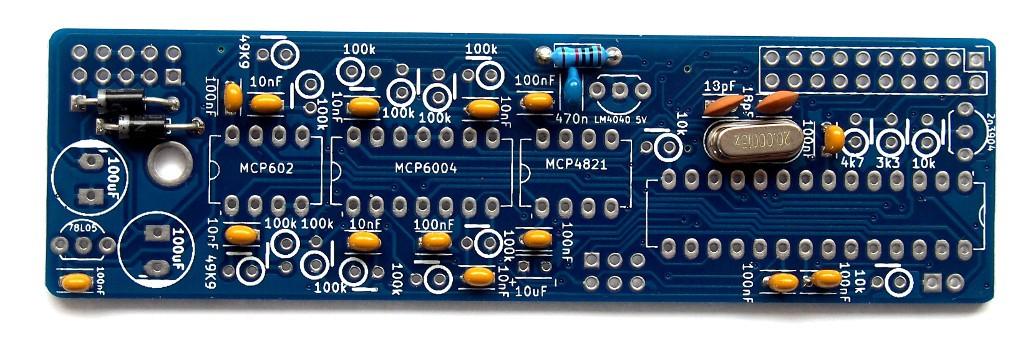
1 Mal-2 assembly guide v.0 SONIC POTIONS Schematic and BOM The BOM can be found on Google Docs Prepare the PCB Separate the PCBs using some pliers.


2 PCB We start with the lower PCB and assemble it beginning with the flat and working our way to the high components. Diodes Diodes are polarized parts, so the orientation is important. You have to align the silver ring on the diode to the line on the silkscreen as seen on the picture. N589 diode Quantity 2 2 Part No. D D2 Polarized part. Orientation is important. Look at the silver line on the diode and silkscreen.


3 Ceramic capacitors!!!attention!!! There is an error on the silkscreen. C and C6 are 220pF capacitors, NOT 0nF as indicated on the PCB. The ceramic capacitors are non polarized parts. So the orientation does not matter. or Quantity 00nF 8 0nF 4 470nF Has "04" written on it Has "03" written on it Has "474" written on it 3


4 8pF 2 Has "80" written on it 220pf 2 Has "22" written on it 4


5 Flat resistors Quantity 0k brown, black, black, red, brown Quartz Quantity 20 MHz quartz Generates the clock for the microcontroller 5
6 6


7 IC sockets Align the notch of the IC sockets with the notch on the silkscreen. The notch indicates the IC orientation. Quantity DIP 8 2 Notch left DIP 4 Notch left DIP 28 Notch right Standing resistors Next are the upright resistors. Just bend one leg over so it is parallel to the other. 7
: brown, black yellow gold Transistor and Voltage Regulator Quantity 78L05 voltage regulator")
8 Quantity 0k 3 brown, black, black, red, brown if % metal film (blue body): brown, black, black, orange, brown 00k 0 3k3 The 3k3 resistor must not be populated, otherwise the gate out will only be 2V 4k7 yellow, violet, black, brown, brown 49k9 2 yellow, white, white, red, brown if 5% carbon (brown body): brown, black yellow gold Transistor and Voltage Regulator Quantity 78L05 voltage regulator 5V voltage regulator. 8


9 LM Reference voltage source. Generates -5V that is used for the pots and CVs 2N3904 transistor Gate out buffer Big capacitors For these capacitors the orientation is important! On both cap types the long leg is positive (+) and the short leg is negative (-). On the electrolytic capacitors the negative side is also marked with a big white stripe. The footprints on the silkscreen have a '+' sign on the side where the long leg has to be inserted. Some tantalum capacitor legs have equal length. In that case you will find a small '+' sign printed on the cap that indicates the positive side of the part. 9


10 0uF tantalum capacitor Quantity Polarized part! Long leg is + Short leg is Has "06" written on it 00uF electrolytic capacitor 0 2 Polarized part!


11 Board and power connectors Now it s time for the board and power connectors. You have to break apart the long 2x8 pin header into 2x5 and 2x3 pieces. Be careful not to break away single pins. A side cutter may help here. Also pay attention to which side of the PCB the parts have to be soldered. The female socket goes on top of the PCB, the other connectors to the bottom. Quantity 2x0 female Board connector top 2x5 male Power connector bottom 2x3 male x2 male Speed range select jumper Speed range select AVR ISP connector bottom


12 The blue jumper selects the speed range of the module. With the jumper in place the module runs slow, barely touching audio range, but with modulation cycles down to 0-5 minutes. With the jumper removed it runs up to audio range, but the low end is reduced. 2


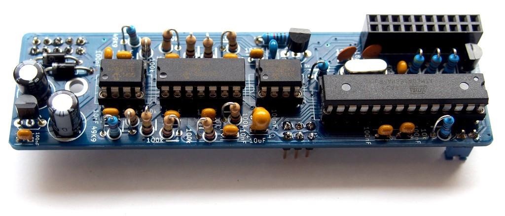
13 Insert ICs Quantity Programmed Atmega 68 Microcontroller MCP6002 Dual OpAmp MCP6004 Quad OpAmp MCP482 DAC 3


14 Interlude Congratulations on finishing the first PCB! Now is a good time to drink a nice cup of tea or coffee, take a step back for a few minutes and get a clear head. Trust me it s worth it! PCB 2 Wasn t that refreshing? Then back to work with the 2nd PCB. As before we start with the flat parts and work our way up higher and higher. Flat resistors Quantity 00 ohm brown, black, black, black, brown If % metal film (blue body): brown, black, black, orange, brown 00k If 5% carbon (brown body): brown, black yellow gold 4


15 Capacitors Quantity 00nF 2 Has "04" written on it 220pF film capacitor 2 Has "220" written on it 5

16 IC socket Align the notch of the IC sockets with the notch on the silkscreen. The notch indicates the IC orientation. Quantity DIP 8 Align notch with silkscreen Standing resistors Quantity 00 ohm 2 brown, black, black, black, brown 00k 7 brown, black, black, orange, brown 4k2 yellow, brown, red, red, brown 6

17 M 2 brown, black, black, yellow, brown 49k9 yellow, white, white, red, brown 7


18 Uni/Bipolar jumper This jumper sets the CV output range. Uni equals 0V-0V and BI equals -5V to 5V. You have to decide where you want it now! If unsure set it to bipolar. This jumper is not accessible after the panel is mounted. I'm sorry for that, but there was just no other place to put this on the PCB. If you think you will change this setting very often, consider attaching some wires and a switch instead. If the jumper is set to Uni, the Voltage range is 0-0V, on the Bi setting it is -5V to 5V. Quantity x3 pin header male 8
19 9


20 Pin array bottom Solder the pin header to the bottom of the PCB. Quantity 2x0 pin header male 20


21 Switch You have to remove the metal part on one side of the switch to fit the PCB. The side does not matter. Just bend it up and down a few times until it comes off. Make sure to solder the switch completely straight. Solder a single leg first, adjust position, then solder the rest of the pins. Quantity SPST switch Selects the operation mode 2
22 Insert IC Insert the TL072 IC into the socket. The small round dot on the IC marks pin and goes to the side of the socket with the notch (left). Quantity TL072 dual OpAmp 22


23 Bolt and Screw Put an M3 screw in the hole of the PCB from the top and screw the mm bolt to the bottom. The bolt will secure the other PCB later on. Quantity M3 screw mm bolt Attention! For the following steps parts have to be placed on the PCB but not soldered before the frontpanel is attached. This is to make sure all components are properly aligned with the panel and fit through the holes. 23


24 Jacks Remove the nuts and put the 4 audio jacks on the PCB. Do not solder yet! Quantity 3.5mm Jacks 4 LED The LED is a polarized part. The long leg has to be put in the upper pad marked with a '+' sign. Do not solder yet! Quantity 3mm LED green 24


25 3mm LED bi-color Potentiometer Same for the pots. Put them in place but do not solder yet. Quantity 9mm potentiometer 0k linear 2 25


26 9mm tall trimmer 0k linear 2 26


27 Panel Quantity Aluminum Panel washer 2 nuts 2 plastic spacers 4 First, put the plastic spacers on the threading of the pots. 2 spacers each. Since the jacks are a bit higher than the body of the potentiometers, these spacers assure that you can screw the nuts from the pots tight to the frontpanel. 27


28 Then attach the panel and secure the 2 metal pots with a washer and a nut each. 28


29 The jacks should be attached with their nuts, too. Push up the LEDs so they are flat with the front panel. Make sure everything is properly aligned and straight. Solder the components Now solder pin on each component. Before soldering the other pins, make sure that all components are straight. Then solder the rest of the pins. This method assures that everything fits into the panel later on. Cut off the pins of the jacks as flat as possible, otherwise they may touch the caps on the lower PCB later on. Be careful, the legs of the jacks are like small powered high energy projectiles when cut off with wire cutters! (You'll shoot your eye out!) Ignore the missing bolt on the following pictures. 29


30 Knobs Quantity Big knob Big cap Small knob Small cap Attach the knobs and turn the pots to their minimum position. Then put the caps onto the knobs with their marker pointing to 7 o'clock 30


31 Final assembly Attach the lower to the upper PCB and attach it with the M3 screw to the bolt. Make sure the electrolytic capacitors do not touch the upper PCB!!! 3

32 Attach the power cable with regard to the proper orientation (red stripe to the bottom of the PCB) Test the module Congratulations! You should now have a working Mal-2 module in front of you. Turn both knobs to the maximum position and attach it to a power source. The upper LED should flash green for a moment and then start to wildly alternate between red and green. The lower LED should start to flash as well. If that is not the case, turn off the power and re-check your work! Now turn the upper knob to the left. The blinking of the LEDs should get slower, and turn into a fading from red to green and back again. If that works chances are good that you did a great job and the module is working. Proceed with the normal user manual and have fun with your new module! 32
33 Firmware Updates The firmware can be updated with an audio file. This procedure is not necessary with a newly bought module, as the latest firmware is flashed by us when the AVR leaves our workshop. Update procedure When the module is powered up, the CV LED flashes very fast in green. If the switch on the module is moved during this time, the flashing LED color changes to red. This indicates that the module is waiting for an audio firmware update on the change CV input (right jack). A mobile phone output has not enough voltage to properly drive the CV input (normally.2v peak to peak) so you might need to use a mixer between the phone and the module. You can also use another module that is able to amplify the signal (I used the Intellijel VCA for this purpose) or a louder audio source like your computer soundcard. Play back the audio file. The LED should start flashing green in a slower speed, indicating successfully received packages. If the LEDs stays off or turns a solid red your volume is probably too low. When it is red you can just start over by moving the switch again and turn the volume up a bit. After an successful update the module will automatically reboot and run the new firmware. 33
MAIN PCB (The small one) OPEN MAIN BOARD BAG A
 OPEN MAIN BOARD BAG A") THANKS FOR CHOOSING ONE OF OUR KITS! This manual has been written taking into account the common issues that we often find people experience in our workshops. The order in which the components are placed
THANKS FOR CHOOSING ONE OF OUR KITS! This manual has been written taking into account the common issues that we often find people experience in our workshops. The order in which the components are placed
Main PCB (The small one)
") Thanks for choosing our kits! This manual is written taking with the problems that we usually find in our workshops in mind. Also the order is meant to make assembly as easy as possible. Some steps are
Thanks for choosing our kits! This manual is written taking with the problems that we usually find in our workshops in mind. Also the order is meant to make assembly as easy as possible. Some steps are
ANTUMBRA FADE MANUAL
 ANTUMBRA FADE MANUAL TABLE OF CONTENTS 01. INSTALLATION 4 02. BACK 5 03. FRONT 6 04. USE 7 05. LINK 8 06. BILL OF MATERIALS 9 07. BUILD NOTES 10 08. BACK 11 09. FRONT 14 10. MODIFICATION 15 11. FINISHED
Galilean Moons. dual amplitude transmutator. DIY ASSEMBLY MANUAL v1.02
 Galilean Moons dual amplitude transmutator DIY ASSEMBLY MANUAL v1.02 Contents Contents... 2 Introduction... 3 Eurorack Kit Assembly... 4 Resistors... 4 IC Sockets... 5 Ceramic/Film Capacitors... 5 Transistors
Tube Cricket Build Guide
 Tube Cricket Build Guide The Tube Cricket is a small-wattage amp that puts out about 1 watt of audio power. With a 12AU7 tube-preamp and a JRC386 power amp, the Tube Cricket gives you great tone in a compact
Documentation VFD clock 8 a clock
 Documentation VFD clock 8 a clock This documentation is protected by our copyright. It must not be used for commercial purposes. Congratulations on your purchase of your VFD clock. To guarantee success
MAKE AN RGB CONTROL KNOB.
 MAKE AN RGB CONTROL KNOB. This is a knob based colour changing controller that uses a custom programmed microcontroller to pack a lot of features into a small affordable kit. The module can drive up to
DIY KIT MHZ 8-DIGIT FREQUENCY METER
 This kit is a stand-alone frequency meter capable of measuring repetitive signals up to a frequency of 50MHz. It has two frequency ranges (15 and 50 MHz) as well as two sampling rates (0.1 and 1 second).
Introduction 1. Green status LED, controlled by output signal ST. Sounder, controlled by output signal Q6. Push switch on input D6
 Introduction 1 Welcome to the GENIE microcontroller system! The activity kit allows you to experiment with a wide variety of inputs and outputs... so why not try reading sensors, controlling lights or
Total solder points: 123 Difficulty level: beginner 1. advanced AUDIO ANALYZER K8098. audio gea Give your. . high-tech ILLUSTRATED ASSEMBLY MANUAL
 Total solder points: 123 Difficulty level: beginner 1 2 3 4 5 advanced AUDIO ANALYZER K8098 ra audio gea Give your. look high-tech ILLUSTRATED ASSEMBLY MANUAL H8098IP-1 Features & Specifications Features
GUIDE TO ASSEMBLY OF ERICA SYNTHS DELAY MODULE
 If you are reading this, most probably, you are about to build Erica Synths DIY DELAY module. The module is 4mm deep, skiff friendly, has solid mechanical construction and doesn t require wiring. Erica
VU-1 VU Meter Kit Volume Unit Meter
 VU-1 VU Meter Kit Volume Unit Meter Simplicity Counts, Detail Matters. No part of this document may be reproduced, either mechanically or electronically, posted online on the Internet, in whole or in part,
ASM-2 Manual Appendix A
 ASM-2 Manual Appendix A Assembly Guidelines June 30 th, 2005 Please note that this document is still currently under revision and we apologise for any errors or omissions. Readers should feel free to e-mail
Introduction 1. Digital inputs D6 and D7. Battery connects here (red wire to +V, black wire to 0V )
") Introduction 1 Welcome to the magical world of GENIE! The project board is ideal when you want to add intelligence to other design or electronics projects. Simply wire up your inputs and outputs and away
Introduction 1 Welcome to the magical world of GENIE! The project board is ideal when you want to add intelligence to other design or electronics projects. Simply wire up your inputs and outputs and away
N3ZI Digital Dial Manual For kit with Serial LCD Rev 3.04 Aug 2012
 N3ZI Digital Dial Manual For kit with Serial LCD Rev 3.04 Aug 2012 Kit properly assembled and configured for Standard Serial LCD (LCD Not yet connected) Kit Components Item Qty Designator Part Color/Marking
And there are countless others. It s probably best to study these before you continue..
 Prerequisites Soldering iron (nothing too special, any cheap-ass iron will do) Soldering tin Dupont wire (to hook up panel mount connectors) Diagonal cutters for cutting away all the legs of soldered components
N3ZI Digital Dial Manual For kit with Backlit LCD Rev 4.00 Jan 2013 PCB
 N3ZI Digital Dial Manual For kit with Backlit LCD Rev 4.00 Jan 2013 PCB Kit Components Item Qty Designator Part Color/Marking PCB 1 LCD Display 1 LCD 1602 Volt Regulator 1 U1 78L05, Black TO-92 Prescaler
Multi-Key v2.4 Multi-Function Amplifier Keying Interface
 Multi-Key v2.4 Multi-Function Amplifier Keying Interface ASSEMBLY & OPERATION INSTRUCTIONS INTRODUCTION The Harbach Electronics, LLC Multi-Key is a multi-function external device designed for the safe
TECHNOLOGY WILL SAVE US: THE LUMIPHONE
 TECHNOLOGY WILL SAVE US: THE LUMIPHONE This is a step-by-step guide to soldering your own Lumiphone. The equipment you should have at your station: goggles, soldering mat, soldering Iron, solder and side
Build Your Own Clone Super 8 Kit Instructions
 Build Your Own Clone Super 8 Kit Instructions Warranty: BYOC, Inc. guarantees that your kit will be complete and that all parts and components will arrive as described, functioning and free of defect.
Introduction 1. Green status LED, controlled by output signal ST
 Introduction 1 Welcome to the magical world of GENIE! The project board is ideal when you want to add intelligence to other design or electronics projects. Simply wire up your inputs and outputs and away
XTAL Bank DDS Version 0.02 Sept Preliminary, highly likely to contain numerous errors
 XTAL Bank DDS Version 002 Sept 7 2012 Preliminary, highly likely to contain numerous errors The photo above shows the fully assembled Xtal Bank DDS with 2 DDS modules installed (The kit is normally only
TKEY-K16. Touch CW automatic electronic keyer. (No moving parts no contacts) Assembly manual. Last review: March 15, 2018
 Assembly manual. Last review: March 15, 2018") TKEY-K16 Touch CW automatic electronic keyer (No moving parts no contacts) Assembly manual Last review: March 15, 2018 Commands and use manual of the K16 and Updates and news: www.ea3gcy.com Thanks for
TKEY-K16 Touch CW automatic electronic keyer (No moving parts no contacts) Assembly manual Last review: March 15, 2018 Commands and use manual of the K16 and Updates and news: www.ea3gcy.com Thanks for
Color Organ Triple Deluxe II.
 http://wwwinstructablescom/id/color-organ-triple-deluxe-ii/ Food Living Outside Play Technology Workshop Color Organ Triple Deluxe II by ledartist on January 13, 2013 Table of Contents Color Organ Triple
DIY Guide - Building Franky v1.1, the SEGA Audio and Videocard for MSX
 DIY Guide - Building Franky v1.1, the SEGA Audio and Videocard for MSX 2015 FRS & MSXpró. Translation by FRS and Supersoniqs. Table of Contents Introduction... 3 Materials needed... 3 Audio volume boost...
SN-Class Nixie Clock Kits
 Assembly Instructions And User Guide SN-Class Nixie Clock Kits - 1 - REVISION HISTORY Issue Date Reason for Issue Number 1 20 November 2017 New document - 2 - 1. INTRODUCTION 1.1 About the How can the
RF Nomad Semi-SMT. SDIY Kit Assembly Manual
 RF Nomad Semi-SMT Introduction Thanks for purchasing the RF Nomad SDIY kit from Evaton Technologies! The RF Nomad SDIY kit is a voltage-controlled shortwave radio receiver in Eurorack format. The RF Nomad
Pixie Construction Notes
 Pixie Construction Notes PCB V2a February 4 th 2015 Please note that this document is still currently under revision and we apologise for any errors or omissions. Readers should feel free to e-mail any
DDS VFO CONSTRUCTION MANUAL. DDS VFO Construction Manual Issue 1.1 Page 1
 DDS VFO CONSTRUCTION MANUAL DDS VFO Construction Manual Issue 1.1 Page 1 Important Please read before starting assembly STATIC PRECAUTION The DDS VFO kit contains the following components which can be
Fixed Audio Output for the K2 Don Wilhelm (W3FPR) & Tom Hammond (NØSS) v August 2009
 & Tom Hammond (NØSS) v August 2009") Fixed Audio Output for the K2 Don Wilhelm (W3FPR) & Tom Hammond (NØSS) v. 2.1 06 August 2009 I have had several requests to provide a fixed audio output from the K2. After looking at the circuits that
Fixed Audio Output for the K2 Don Wilhelm (W3FPR) & Tom Hammond (NØSS) v. 2.1 06 August 2009 I have had several requests to provide a fixed audio output from the K2. After looking at the circuits that
Phoenix digital Board, formally known as Shruthi is 100% compatible, in fact it is the same board, same dimensions but with another name.
 Phoenix digital Board, formally known as Shruthi is 00% compatible, in fact it is the same board, same dimensions but with another name. Phoenix control board assembly instructions Schematics and PCB The
Assembly Instructions And User Guide. Nixie FunKlock. FunKlock Issue 4 (1 February 2017)
") Assembly Instructions And User Guide Nixie FunKlock - 1 - Issue Number Date REVISION HISTORY 4 1 February 2017 New diode for D2 3 27 December 2013 C7 / C8 error page 15 2 7 November 2013 Errors corrected
Assembly Instructions And User Guide Nixie FunKlock - 1 - Issue Number Date REVISION HISTORY 4 1 February 2017 New diode for D2 3 27 December 2013 C7 / C8 error page 15 2 7 November 2013 Errors corrected
Atari PICO Composite Mod Board Installation Instructions:
 Atari PICO Composite Mod Board Installation Instructions: Installation Guide 6 Switch Atari 2600 6 Switch Video Mod Installation Guide Disclaimer: I am not responsible for any damage done to your Atari.
While the parts are already inventoried at the factory, please verify the inventory check as you go:
 Thank you for purchasing the kit for building the WJ9J DTMF controller. After building, you should read the document on operation (WJ9JDTMFControllerV5.pdf) in order to use. This is also in the link in
Nixie Clock Kit IN-12B color LED backlit Operation Manual Nixie Clock Kit IN-12B V6.0 ( All Right Reserved 2015 )
") Nixie Clock Kit IN-B color LED backlit Operation Manual Nixie Clock Kit IN-B V. ( All Right Reserved ) - - Operation Manual IN-B Nixie Clock Power for your Nixie Clock The clock does not include a wall
Nixie Clock Kit IN-B color LED backlit Operation Manual Nixie Clock Kit IN-B V. ( All Right Reserved ) - - Operation Manual IN-B Nixie Clock Power for your Nixie Clock The clock does not include a wall
Mini-Yack Iambic Keyer
 Mini-Yack Iambic Keyer Assembly Instructions Mini-Yack is a "bare bones" Iambic keyer for embedding into QRP and home brew equipment. The keyer has the following features: Keying from 1-50WPM YACK memory
Nixie Clock Type Frank 2 Z570M
 Assembly Instructions And User Guide Nixie Clock Type Frank 2 Z570M Software version: 7R PCB Revision: 11 April 09-1 - 1. INTRODUCTION 1.1 About the clock Nixie clock type Frank 2 is a compact design with
Bill of Materials: Super Simple Water Level Control PART NO
 Super Simple Water Level Control PART NO. 2169109 Design a simple water controller in which electrodes are required to sense high and low water levels in a tank. Whenever the water level falls below the
MONO AMPLIFIER KIT ESSENTIAL INFORMATION. Version 2.2 CREATE YOUR OWN SPEAKER DOCK WITH THIS
 ESSENTIAL INFORMATION BUILD INSTRUCTIONS CHECKING YOUR PCB & FAULT-FINDING MECHANICAL DETAILS HOW THE KIT WORKS CREATE YOUR OWN SPEAKER DOCK WITH THIS MONO AMPLIFIER KIT Version 2.2 Build Instructions
VU Meter Buffer DIY Kit
 VU Meter Buffer DIY Kit Warning This document is distributed for educational purposes only. This equipment operates at potentially lethal voltages. Only trained, qualified personnel should operate, maintain,
PR-101 STEREO PREAMPLIFIER Phono Preamp ASSEMBLY MANUAL
 PR-101 STEREO PREAMPLIFIER Phono Preamp ASSEMBLY MANUAL 2016 AkitikA LLC All rights reserved Revision 1p18 March 12, 2016 Page 1 of 24 Table of Contents Table of Contents... 2 Table of Figures... 2 Section
Parts Checklist - Please note there is no resistor R3. Diodes, LED and transistors are polarized see construction stages
 Xtal Check Kit build Read me first! -------- UPDATED GUIDE------ September 12, 2018--------- The following steps are designed to get your Xtal check kit built and operational. This is a good beginner s
ADD AN AUDIO MESSAGE TO YOUR PRODUCT WITH THIS RECORD & PLAYBACK KIT
 ADD AN AUDIO MESSAGE TO YOUR PRODUCT WITH THIS RECORD & PLAYBACK KIT BUILD INSTRUCTIONS Before you start take a look at the Printed Circuit Board (PCB). The components go in the side with the writing on
Nixie Clock Kit V1.08 Assembly and Operation
 Nixie Clock Kit V1.08 Assembly and Operation Hardware Revision 14.05.2005 Software Version 6.0 Revision 19.04.2006 This document is copyrighted. No parts of this documentation may be used commercially.
nonlinearcircuits cellf action build guide & BOM VERS. 1
 nonlinearcircuits cellf action build guide & BOM VERS. 1 Please read thru before soldering anything, there are some component values that need to be changed or decided upon before starting. If you spot
MOD028 GLOCKENSPIEL TECHNO-MUSIC-OLOGY
 MOD028 GLOCKENSPIEL TECHNO-MUSIC-OLOGY MOD028 - Techno-music-ology Kit Contents Motor Controller PCBs 14 220R (red red brown gold) resistors 2 330R (orange orange brown gold) resistors 16 1N4001 diodes
Nixie Clock Type Frank 3
 Assembly Instructions And User Guide Nixie Clock Type Frank 3 Software version: 7R PCB Version: 11 April 09-1 - 1. INTRODUCTION 1.1 About the clock Nixie clock type Frank 3 is a compact design with all
Bill of Materials: Magic Color PART NO
 Magic Color PART NO. 2193838 Magic color is a guessing game. With this game you can surprise your friends and leave them with amazement, how the game guesses what they have in their minds. Only two selections
NewScope-7A Operating Manual
 2016 SIMMCONN Labs, LLC All rights reserved NewScope-7A Operating Manual Preliminary May 13, 2017 NewScope-7A Operating Manual 1 Introduction... 3 1.1 Kit compatibility... 3 2 Initial Inspection... 3 3
COLOUR CHANGING USB LAMP KIT
 TEACHING RESOURCES SCHEMES OF WORK DEVELOPING A SPECIFICATION COMPONENT FACTSHEETS HOW TO SOLDER GUIDE SEE AMAZING LIGHTING EFFECTS WITH THIS COLOUR CHANGING USB LAMP KIT Version 2.1 Index of Sheets TEACHING
Build A Video Switcher
 Build A Video Switcher VIDEOSISTEMAS serviciotecnico@videosistemas.com www.videosistemas.com Reprinted with permission from Electronics Now Magazine September 1997 issue Copyright Gernsback Publications,
ELECTRONIC GAME KIT TEACHING RESOURCES. Version 2.0 BUILD YOUR OWN MEMORY & REACTIONS
 TEACHING RESOURCES SCHEMES OF WORK DEVELOPING A SPECIFICATION COMPONENT FACTSHEETS HOW TO SOLDER GUIDE BUILD YOUR OWN MEMORY & REACTIONS ELECTRONIC GAME KIT Version 2.0 Index of Sheets TEACHING RESOURCES
7 SEGMENT LED DISPLAY KIT
 ESSENTIAL INFORMATION BUILD INSTRUCTIONS CHECKING YOUR PCB & FAULT-FINDING MECHANICAL DETAILS HOW THE KIT WORKS CREATE YOUR OWN SCORE BOARD WITH THIS 7 SEGMENT LED DISPLAY KIT Version 2.0 Which pages of
Nixie Tube Clock Type Marsden
 Assembly Instructions And User Guide Nixie Tube Clock Type Marsden Software version: RTC-1.3 PCB Revision: 16 Aug 10-1 - 1. INTRODUCTION 1.1 About the clock Nixie clock type Marsden is a compact design
Etherwave Plus Field Upgrade Instructions
 Etherwave Plus Field Upgrade Instructions The Etherwave Plus Field Upgrade is an advanced project for upgrading a standard Moog Music Etherwave theremin to the Etherwave Plus. The new features of the Etherwave
Industrial Monitor Update Kit
 Industrial Monitor Update Kit (Bulletin Number 6157) Installation Instructions 2 Table of Contents Table of Contents Industrial Monitor Update Kit... 3 Overview... 3 Part 1 - Initial Preparation... 5 Part
Total solder points: 117 Difficulty level: beginner advanced. RGB Controller K8088 ILLUSTRATED ASSEMBLY MANUAL
 Total solder points: 117 Difficulty level: beginner 1 2 3 4 5 advanced RGB Controller K8088 Control incandescent bulbs, LEDs, common anode led strips, etc... ILLUSTRATED ASSEMBLY MANUAL H8088IP-1 Features
research platform comma.ai, github.com/commaai/neo
 neo research platform comma.ai github.com/commaai/neo 1 suppliers 2 electronics 1. download digikey.csv 2. go to digikey.com/classic/ordering and register or log in 3. click and navigate to the downloaded
DEM 9ULNACK 3.4 GHz. PHEMT LNA amplifier complete kit assembly guide
 DEM 9ULNACK 3.4 GHz. PHEMT LNA amplifier complete kit assembly guide SPECIFICATIONS Noise Figure: < 0.8 db Gain: > 15 db Frequency Range: 3400-3500 MHz Input Voltage: 7-16 VDC Description: The 9ULNACK
Modellbahn Digital Peter Stärz
 Modellbahn Digital Peter Stärz Dresdener Str. 68 D-02977 Hoyerswerda +49 3571 404027 www.firma-staerz.de info@firma-staerz.de 8-fold Track Occupancy Detector for digital systems with two-wire track (e.g.
LP-PAN Preamp Kit Assembly Manual
 LP-PAN Preamp Kit Assembly Manual December 2010 TelePost Incorporated Rev. A9 1 Table of Contents Introduction... 2 Specifications... 3 Parts List... 4 Assembly... 5 Checkout / Schematic... 9 Introduction
FSM User Guide Page 1 of 28
 FSM User Guide Page 1 of 28 Field Strength Meter User Guide and Kit Assembly Instructions PCB V1.1 Important: Always use or print this document in colour as there are references to the colours of components.
ELECTRONIC GAME KIT ESSENTIAL INFORMATION. Version 2.0 BUILD YOUR OWN MEMORY & REACTIONS
 ESSENTIAL INFORMATION BUILD INSTRUCTIONS CHECKING YOUR PCB & FAULT-FINDING MECHANICAL DETAILS HOW THE KIT WORKS BUILD YOUR OWN MEMORY & REACTIONS ELECTRONIC GAME KIT Version 2.0 Build Instructions Before
16 Stage Bi-Directional LED Sequencer
 16 Stage Bi-Directional LED Sequencer The bi-directional sequencer uses a 4 bit binary up/down counter (CD4516) and two "1 of 8 line decoders" (74HC138 or 74HCT138) to generate the popular "Night Rider"
What is the E560? Connecting to the power supply
 PAGE 1 E560 Deflector Shield DIY Kit www.synthtech.com/euro/e560 What is the E560? The Synthesis Technology E560 is a combination frequency shifter, phaser and ring modulator. The audio is mono in, and
WM8725 EVALUATION BOARD USER HANDBOOK. The WM8725 is high performance Stereo DAC.
 w WM8725-EVM WM8725 EVALUATION BOARD USER HANDBOOK INTRODUCTION The WM8725 is high performance Stereo DAC. This evaluation platform and documentation should be used in conjunction with the latest version
GEKCO SUBCARRIER REFERENCE OSCILLATOR MODEL SRO10 OPERATION/SERVICE MANUAL
 GEKCO MODEL SRO10 SUBCARRIER REFERENCE OSCILLATOR OPERATION/SERVICE MANUAL GEKCO Labs PO Box 642 Issaquah, WA 98027 (425) 392-0638 P/N 595-431 REV 5/98 Copyright c 1998 GEKCO Labs All Rights Reserved Printed
8 PIN PIC PROGRAMMABLE BOARD (DEVELOPMENT BOARD & PROJECT BOARD)
") ESSENTIAL INFORMATION BUILD INSTRUCTIONS CHECKING YOUR PCB & FAULT-FINDING MECHANICAL DETAILS HOW THE KIT WORKS LEARN ABOUT PROGRAMMING WITH THIS 8 PIN PIC PROGRAMMABLE BOARD (DEVELOPMENT BOARD & PROJECT
ESSENTIAL INFORMATION BUILD INSTRUCTIONS CHECKING YOUR PCB & FAULT-FINDING MECHANICAL DETAILS HOW THE KIT WORKS LEARN ABOUT PROGRAMMING WITH THIS 8 PIN PIC PROGRAMMABLE BOARD (DEVELOPMENT BOARD & PROJECT
IQPro Construction Notes by Gary Johnson, WB9JPS August 5, 2006
 IQPro Construction Notes by Gary Johnson, WB9JPS August 5, 2006 All parts of the enclosure were fabricated from 0.050 brass sheet, folded and soldered, with 0.187-thick brass strips soldered along edges
Lab 7: Soldering - Traffic Light Controller ReadMeFirst
 Lab 7: Soldering - Traffic Light Controller ReadMeFirst Lab Summary The two-way traffic light controller provides you with a quick project to learn basic soldering skills. Grading for the project has been
QUIZ BUZZER KIT TEACHING RESOURCES. Version 2.0 WHO ANSWERED FIRST? FIND OUT WITH THIS
 TEACHING RESOURCES SCHEMES OF WORK DEVELOPING A SPECIFICATION COMPONENT FACTSHEETS HOW TO SOLDER GUIDE WHO ANSWERED FIRST? FIND OUT WITH THIS QUIZ BUZZER KIT Version 2.0 Index of Sheets TEACHING RESOURCES
Lab 7: Soldering - Traffic Light Controller ReadMeFirst
 Lab 7: Soldering - Traffic Light Controller ReadMeFirst Lab Summary The two way traffic light controller provides you with a quick project to learn basic soldering skills. Grading for the project has been
How To Build Megavolt s Small Buffered JTAG v1.2
 How To Build Megavolt s Small Buffered JTAG v1.2 Abstract A JTAG cable should be considered mandatory equipment for any serious tester. It provides a means to backup the information in the receiver and
Theremino pulsometer
 Theremino System Theremino pulsometer Optical sensor for the arrhythmia detection theremino System - Pulsometer - December 8, 2017 - Page 1 Sensors of all types On the Internet there are many ideas to
Nixie Clock Type Quattro'
 Assembly Instructions And User Guide Nixie Clock Type Quattro' - 1 - Issue Number Date REVISION HISTORY 2 8 Sept 2012 Errors corrected 1 27 July 2012 New document Reason for Issue - 2 - 1.1 Nixie Quattro
Analog Style LED Clock
 Analog Style LED Clock Operation and Assembly Manual For use with PCB Rev 2.1 Copyright 2018 All Rights Reserved. Manual version 2.1c, for use with PCB revision 2.1, Software version 2.0.0. The electronic
Reaction Game Kit MitchElectronics 2019
 Reaction Game Kit MitchElectronics 2019 www.mitchelectronics.co.uk CONTENTS Schematic 3 How It Works 4 Materials 6 Construction 8 Important Information 9 Page 2 SCHEMATIC Page 3 SCHEMATIC EXPLANATION The
Step What to do Expected result What to do if test fails Component tested 1 Visual inspection. Board is accurately assembled
 Fox Delta Amateur Radio Projects & Kits AAZ-0914A 50MHZ Antenna Analyzer Testing Guide by Tony / I2TZK SWR Analyzer 4 steps for a quick test Step What to do Expected result What to do if test fails Component
CADET I SYNC GENERATOR OWNER S MANUAL
 OWNER S MANUAL ABOUT THE CADET SERIES The practice of analog video synthesis has an inspiring legacy of innovators, sharers, and doers. In the early 70's, Dan Sandin released the hardware documentation
1. Uses. 2. Power Supply. 1) Removal or Positioning of Weld Lines. 2) Regulation of the Injection Quantity by Gate Operation
 Removal or Positioning of Weld Lines. 2) Regulation of the Injection Quantity by Gate Operation") 1. Uses YUDO have produced the Sequence Injection Timer - SIT500 Series to provide a means of controlling the mould filling sequence when using Valve Gate Hot- Runner Systems. The Sequence Injection Timer
1. Uses YUDO have produced the Sequence Injection Timer - SIT500 Series to provide a means of controlling the mould filling sequence when using Valve Gate Hot- Runner Systems. The Sequence Injection Timer
ENGR 40M Project 3a: Building an LED Cube
 ENGR 40M Project 3a: Building an LED Cube Lab due before your section, October 31 November 3 1 Introduction In this lab, you ll build a cube of light-emitting diodes (LEDs). The cube is wired to an Arduino,
RECORD & PLAYBACK KIT
 TEACHING RESOURCES SCHEMES OF WORK DEVELOPING A SPECIFICATION COMPONENT FACTSHEETS HOW TO SOLDER GUIDE ADD AN AUDIO MESSAGE TO YOUR PRODUCT WITH THIS RECORD & PLAYBACK KIT Version 2.1 Index of Sheets TEACHING
Technical Information Bulletin
 June 4, 2001 #TIB0003 Units Affected: Model Serial Numbers Model Serial Numbers SVT-2PRO T2PDxxxxxxxxx SVTAV AXVDxxxxxxxxx ATLDxxxxxxxxx BJIDMAxxxxxxx SVT-2PROJ T2PJxxxxxxxxx SVTAVJ BAHJxxxxxxxxx ATLJxxxxxxxxx
Build Your Own Clone Relay Bypass Board Instructions
 Build Your Own Clone Relay Bypass Board Instructions Parts list for the Relay Bypass Board Resistors: 1-2k2/222 (Red/Red/Black/Brown/Brown) 1-10k/103 (Brown/Black/Black/Red/Brown) Capacitors: 2-100n/.1uF/104
Dual Comparator and Gate Delay CV and Audio Processor
 Oakley - Modular Dual Comparator and Gate Delay CV and Audio Processor PCB Issue 1 User s Guide V1.2 Tony Allgood B.Eng PGCE Oakley Sound Systems PENRITH CA10 1HR United Kingdom Introduction This is an
Building a MidiBox LCD Cable
 Building a MidiBox LCD Cable By Jim Henry, 3-Apr-2004 An LCD panel may be connected to the Core module by a 16 conductor flat ribbon cable. A 16 pin insulation displacement connector (IDC) terminates one
MAX2660/MAX2661/MAX2663/MAX2671 Evaluation Kits
 9-382; Rev ; 9/99 MAX2660/MAX266/MAX2663/MAX267 General Description The MAX2660/MAX266/MAX2663/MAX267 evaluation kits simplify evaluation of the MAX2660/MAX266/ MAX2663/MAX267 upconverter s. They enable
Genboard v3 Official build and test guide
 Genboard v3 Official build and test guide 1 Contents: 1 Preparations 2 Assembly 2.1 Checking the PCB 2.2 General parts 2.2.1 EGT/knock 2.2.2 Supply connection, fuse wire 2.2.3 Stepper 2.2.4 Filter inductance
INteractive LED Panel Kits
 INteractive LED Panel Kits A DIY Electronics Project designed by Evil Mad Scientist Laboratories Making the World a Better Place,One Evil Mad Scientist at a Time Support: http://www.evilmadscientist.com/forum/
RVS-8 Repeater Voting System. Assembly Manual Ver 2.1
 RVS-8 Repeater Voting System Assembly Manual Ver 2. LDG Electronics 445 Parran Road St. Leonard MD 20685 Phone: 40-586-277 Fax: 40-586-8475 e-mail: ldg@radix.net Web site: www://radix.net/~ldg Introduction:
Azatrax Model Railroad Track Signal Control - Single Track
 Installation Guide Azatrax Model Railroad Track Signal Control - Single Track TS2 What it is: The TS2 operates one or two trackside block signals (one in each direction) on one track to simulate the block
Panzer 3.0 Assembly Instructions & Checklist
 Panzer 3.0 Assembly Instructions & Checklist Parts Included & Preparation Legend A. 5x Silver M4 Aluminum Screws B. 4x 10-24 Screws C. 8x 4-40 Pan head Screws D. 2x 4-40 Flat head Screws E. 2x 4-40 Nuts
Evaluation Board For ADF Integrated VCO & Frequency Synthesizer
 a Evaluation Board For ADF4360-1 Integrated VCO & Frequency Synthesizer EVAL-ADF4360-1EB1 FEATURES Self-Contained Board for generating RF frequencies Flexibility for Reference Input, Output frequency,
Nixie Clock Type SixNix
 Assembly Instructions And User Guide Nixie Clock Type SixNix - 1 - Issue Number Date REVISION HISTORY Reason for Issue 6 20 March 2014 Removed WWVB Support 5 14 July 2012 New Board Issue - 19 July 12 4
The NorCal SMT Dummy Load Assembly and Operating Manual Rev. 1.0 January 4, 2005
 The NorCal SMT Dummy Load Assembly and Operating Manual Rev. 1.0 January 4, 2005 Copyright 2005 W3CD 1 1. Introduction The NorCal SMT Dummy Load is a practice kit for anyone wishing to gain some experience
These are the illustrated step-by-step guidelines for upgrading your Quad 34 with the Dada Electronics upgrade-kit.
 Quad 34 DIY illustrated guidelines version 2.12 These are the illustrated step-by-step guidelines for upgrading your Quad 34 with the Dada Electronics upgrade-kit. The Quad 34 is a very good preamplifier,
USER MANUAL. GOLDMUND LOGOS 1N-2N SPEAKER SYSTEM Active Speaker
 USER MANUAL GOLDMUND LOGOS 1N-2N SPEAKER SYSTEM Active Speaker Thank you for purchasing the Goldmund LOGOS 1N-2N SPEAKER SYSTEM The Goldmund Logos line fully incorporates the technological expertise developed
Prototyping: Considerations From the Bread Board for the Final Product
 Prototyping: Considerations From the Bread Board for the Final Product A. Jensen Newman, Ph.D., EIT Principal Investigator: Power, Energy, Controls, and Electronics UT Dallas Applied Research Center 716-544-3184
UAV Ultimate Atari Video A7800
 UAV Ultimate Atari Video A7800 Basic Install guide because this is really easy mod to do! The UAV is a wonderful piece of tech for what it can do. To summarize, the UAV is a replacement video encoder and
DL-1A. RF dummy load - 50Ω 20W. Assembly manual. Last update: May 1, Thank you for constructing the DL-1A dummy load kit
 DL-1A RF dummy load - 50Ω 20W Assembly manual Last update: May 1, 2016 ea3gcy@gmail.com Updates and news at: www.qsl.net/ea3gcy Thank you for constructing the DL-1A dummy load kit Have fun assembling it