Transducers and Sensors
|
|
|
- Janel McDaniel
- 6 years ago
- Views:
Transcription
1 Transducers and Sensors Dr. Ibrahim Al-Naimi Chapter THREE Transducers and Sensors 1
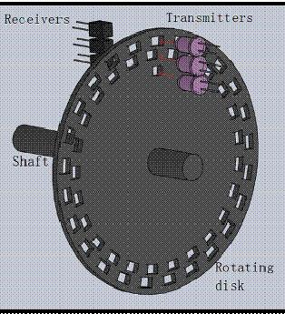
2 Digital transducers are defined as transducers with a digital output. Transducers available at large are primary analogue at nature, and some form of conversion is needed to convert to transform them into digital form. Analogue transducers with A/D convertors can serve the purpose of digital transducers. However, this introduces an additional uncertainty, that of the converter. Inconsequence, overall accuracy and resolution are likely to be affected. Mechanical disks (or bar) with optical receivers and transmitters can act as digital displacement transducers. This type of transducers called optical encoder. Optical encoders can be used to measure linear and angular displacements. Therefore, optical encoders can be classified as: Rotary encoders Linear encoders 2

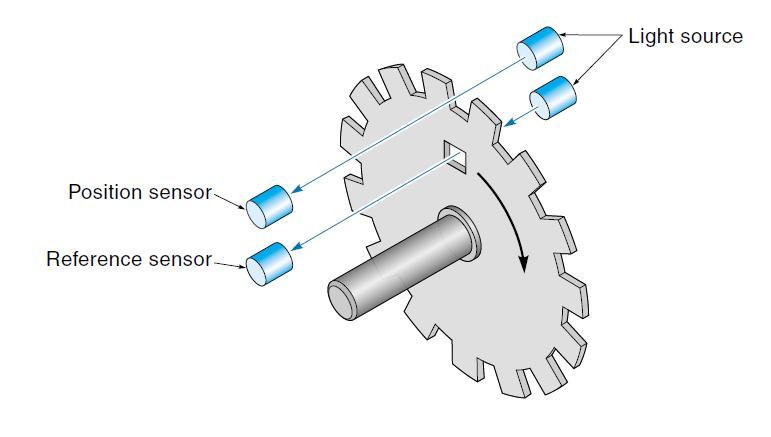
3 Optical Rotary Encoders An optical rotary encoder produces angular position data directly in digital form, eliminating any need for the ADC converter. The concept is illustrated in following figure, which shows a slotted disk attached to a shaft. A light source (LED) and light receiver (phototransistor or photodiode) arrangement are mounted so that the slots pass the light beam as the disk rotates. The angle of the shaft is deduced from the output of the photocell. There are two types of optical rotary encoders: the absolute encoder and the incremental encoder. Optical Rotary Encoders 3
4 The output of the absolute rotary encoder is in the form of a binary word which is proportional to the angle of the shaft. The absolute encoder does not need to be homed because when it is energized, it simply outputs the shaft angle as a digital value. Absolute optical encoders use a glass or plastic disk marked off with a pattern of concentric tracks as shown in the figure. A separate light beam is sent through each track to individual photo sensors. Each photo sensor contributes 1 bit to the output digital word. The encoder in the figure outputs a 4-bit word with the LSB coming from the outer track (note that this is for illustrative purposes only and a 4-bit encoder is of little practical use). The disk is divided into 16 sectors, so the resolution in this case is 360 /16 =
. The encoder shaft would therefore be at an angle of 13 x 22.5 degrees = 292.")
 yield 360 /256 = 1.4 /state, and ten tracks (providing 1024 states) yield 360 /1024 = 0.35 /state. 5")
5 The absolute angle of the encoder shaft can be found by multiplying the binary output of the encoder times the resolution. For example, assume our 4-bit encoder has an output of 1101 (decimal 13). The encoder shaft would therefore be at an angle of 13 x 22.5 degrees = degrees. Because of the relatively poor resolution of this encoder, the shaft could be at some angle between degrees and degrees. For better resolution, more tracks would be required. For example, eight tracks (providing 256 states) yield 360 /256 = 1.4 /state, and ten tracks (providing 1024 states) yield 360 /1024 = 0.35 /state. 5
6 An advantage of this type of encoder is that the output is in straightforward digital form and, like a pot, always gives the absolute position. This is in contrast to the incremental encoder that, as will be shown, provides only a relative position. A disadvantage of the absolute encoder is that it is relatively expensive because it requires that many photocells be mounted and aligned very precisely If the absolute optical encoder is not properly aligned, it may occasionally report completely erroneous data. The following figure illustrates this situation, and it occurs when more than 1 bit changes at a time, say, from sector 7 (0111) to 8 (1000). In the figure, the photo sensors are not exactly in a straight line. In this case, sensor B1 is out of alignment (it s ahead) and switches from a 1 to a 0 before the others. This causes a momentary erroneous output of 5 (0101). If the computer requests data during this transition time, it would get the wrong answer. 6
7 One inherent problem that is encountered with binary output absolute encoders occurs when the output of the encoder changes its value. Consider our 4-bit binary encoder when it changes from 7 (binary 0111) to 8 (binary 1000). Notice that in this case, the state of all four of its output bits change value. If we were to capture the output of the encoder while these four outputs are changing state, it is likely that we will read an erroneous value. The reason for this is that because of the variations in slew rates of the photo-transistors and any small alignment errors in the relative positions of the phototransistors, it is unlikely that all four of the outputs will change at exactly the same instant. 7
8 For this reason, all binary output encoders include one additional output line called data valid (also called data available, or strobe). This is an output that, as the encoder is rotated, goes false for the very short instant while the outputs are changing state. As soon as the outputs are settled, the data valid line goes true, indicating that it is safe to read the data. This is illustrated in the timing diagram in the following figure. 8
9 The second solution is to use the Grey code on the disk instead of the straight binary code as shown in the following figure. Gray code requires the same number of bits to achieve the same resolution as a binary encoder equivalent. However, the counting pattern is established so that, as the angle increases or decreases, no more than one output bit changes at a given time, i.e. only 1 bit changes between any two sectors. If the photo sensors are out of line, the worst that could happen is that the output would switch early or late. Put another way, the error can never be more than the value of 1 LSB when using the Grey code. 9
10 Converting Binary to Gray: 1. Write the binary number to be converted and add a leading zero (on the left side). 2. Exclusive-OR each pair of bits in the binary number together and write the resulting bits below the original number. Converting Gray to Binary: 1. Write the gray code number to be converted and add a leading zero (on the left side). 2. Beginning with the leftmost digit (the added zero), perform a chain addition of all the bits, writing the "running sum" as you go. The incremental optical encoder has one track of equally spaced slots. Position is determined by counting the number of slots that pass by a photo sensor, where each slot represents a known angle. This system requires an initial reference point, which may come from a second sensor on an inner track or simply from a mechanical stop or limit switch. In many applications, the shaft being monitored will be cycling back-and-forth, stopping at various angles. To keep track of the position, the controller must know which direction the disk is turning as well as the number of slots passed. A single photo sensor cannot convey which direction the disk is rotating; however, a clever system using two sensors can 10
11 11
12 In the following, the two sensors, V1 and V2, are located slightly apart from each other on the same track. For this example, V1 is initially off (well, almost you can see it is half-covered up), and V2 is on. Now imagine that the disk starts to rotate CCW. The first thing that happens is that V1 comes completely on (while V2 remains on). After more rotation, V2 goes off, and slightly later V1 goes off again. Figure (b) shows the waveform for V1 and V2. Now consider what happens when the disk is rotated in the CW direction [starting again from the position shown in Figure (a)]. This time V1 goes off immediately, and V2 stays on for half a slot and then goes off. Later V1 comes on, followed by V2 coming on. Figure (c) shows the waveforms generated by V1 and V2. Compare the two sets of waveforms, notice that in the CCW case V2 leads V1 by 90, whereas for the CW case V1 is leading V2 by 90. This difference in phase determines which direction the disk is turning. 12
13 1. If rising edge in v1 when v2 is logic high CW rotation 2. If falling edge in v1 when v2 is logic high CCW rotation Incremental encoders are specified by the number of pulses per revolution that is produced by either the phase A or phase B output. By dividing the number of pulses per revolution into 360 degrees, we get the number of degrees per pulse (called the resolution). The resolution is the smallest change in shaft angle that can be detected by the encoder. For example, a 3600 pulse incremental encoder has a resolution of 360 degrees / 3600 = 0.1 degree. 13
14 An incremental encoder can be used to extract three pieces of information about a rotating shaft. First, by counting the number of pulses received and multiplying the count by the encoder s resolution, we can determine how far the shaft has been rotated in degrees. Second, by viewing the phase relationship between the phase A and phase B outputs, we can determine which direction the shaft is being rotated. Third, by counting the number of pulses received from either output during a fixed time period, we can calculate the angular velocity in either radians per second or RPMs. When an incremental encoder is switched on, it simply outputs a 1 or 0 on its phase A and phase B output lines. This does not give any initial information about the angular position of the encoder shaft. In other words, the incremental encoder gives relative position information, with the reference position being the angle of the shaft when the encoder was energized. The only way an incremental encoder can be used to provide absolute position information is for the encoder shaft to be homed after it is powered-up. This requires some other external device (such as a slotted disk) to provide this home position reference. Some incremental encoders have a third output signal named home that provides one pulse per revolution and can be used for homing the encoder. 14

15 The main advantage of an absolute encoder is its ability to provide absolute angle readings (within a full 360 rotation) ). Hence, if a reading is missed, it will not affect the next reading. Specifically, the digital output uniquely corresponds to a physical rotation of the code disk, and hence a particular reading is not dependent on the accuracy of a previous reading. This provides immunity to data failure. A missed pulse (or, a data failure of some sort) in an incremental encoder would carry an error into the subsequent readings until the counter is cleared. An incremental encoder has to be powered throughout operation of the device. Thus, a power failure can introduce an error unless the reading is reinitialized (or, calibrated). An absolute encoder has the advantage that it needs to be powered and monitored only when a reading is taken. 15
Decade Counters Mod-5 counter: Decade Counter:
 Decade Counters We can design a decade counter using cascade of mod-5 and mod-2 counters. Mod-2 counter is just a single flip-flop with the two stable states as 0 and 1. Mod-5 counter: A typical mod-5
UNIT V 8051 Microcontroller based Systems Design
 UNIT V 8051 Microcontroller based Systems Design INTERFACING TO ALPHANUMERIC DISPLAYS Many microprocessor-controlled instruments and machines need to display letters of the alphabet and numbers. Light
EM1. Transmissive Optical Encoder Module Page 1 of 8. Description. Features
 Description Page 1 of 8 The EM1 is a transmissive optical encoder module designed to be an improved replacement for the HEDS-9000 series encoder module. This module is designed to detect rotary or linear
EM1. Transmissive Optical Encoder Module Page 1 of 9. Description. Features
 Description Page 1 of 9 The EM1 is a transmissive optical encoder module designed to be an improved replacement for the HEDS-9000 series encoder module. This module is designed to detect rotary or linear
Designing Intelligence into Commutation Encoders
 I Designing Intelligence into Commutation Encoders By: Jeff Smoot, CUI Inc C U I NC Encoder users traditionally have been reluctant to change with good reason. Motor control on the factory floor or in
ni.com Sensor Measurement Fundamentals Series
 Sensor Measurement Fundamentals Series Position and Frequency Measurements Key Takeaways Encoder basics Counter fundamentals How to take a position measurement How to take a digital frequency measurement
Revision 1.2d
 Specifications subject to change without notice 0 of 16 Universal Encoder Checker Universal Encoder Checker...1 Description...2 Components...2 Encoder Checker and Adapter Connections...2 Warning: High
IT T35 Digital system desigm y - ii /s - iii
 UNIT - III Sequential Logic I Sequential circuits: latches flip flops analysis of clocked sequential circuits state reduction and assignments Registers and Counters: Registers shift registers ripple counters
EM1. Transmissive Optical Encoder Module Page 1 of 8. Description. Features
 Description Page 1 of 8 The EM1 is a transmissive optical encoder module. This module is designed to detect rotary or linear position when used together with a codewheel or linear strip. The EM1 consists
Encoders - Measuring rotation of a wheel or
 Encoders - Measuring rotation of a wheel or other shaft Encoders are devices for measuring the rotation of a spinning shaft. Encoders are typically used to measure the distance a wheel has turned which
Session 1 Introduction to Data Acquisition and Real-Time Control
 EE-371 CONTROL SYSTEMS LABORATORY Session 1 Introduction to Data Acquisition and Real-Time Control Purpose The objectives of this session are To gain familiarity with the MultiQ3 board and WinCon software.
CATHODE RAY OSCILLOSCOPE. Basic block diagrams Principle of operation Measurement of voltage, current and frequency
 CATHODE RAY OSCILLOSCOPE Basic block diagrams Principle of operation Measurement of voltage, current and frequency 103 INTRODUCTION: The cathode-ray oscilloscope (CRO) is a multipurpose display instrument
Analogue Inputs Resolution Assignment
 Analogue Inputs Resolution Assignment a) Describe the relationship between the number of bits used in an analogue signal and the resolution available. b) A system has a level sensor which measures the
Optical Technologies Micro Motion Absolute, Technology Overview & Programming
 Optical Technologies Micro Motion Absolute, Technology Overview & Programming TN-1003 REV 180531 THE CHALLENGE When an incremental encoder is turned on, the device needs to report accurate location information
Considerations for Specifying, Installing and Interfacing Rotary Incremental Optical Encoders
 Considerations for Specifying, Installing and Interfacing Rotary Incremental Optical Encoders Scott Hewitt, President SICK STEGMANN, INC. Dayton, OH www.stegmann.com sales@stegmann.com 800-811-9110 The
Sealed Linear Encoders with Single-Field Scanning
 Linear Encoders Angle Encoders Sealed Linear Encoders with Single-Field Scanning Rotary Encoders 3-D Touch Probes Digital Readouts Controls HEIDENHAIN linear encoders are used as position measuring systems
Transmitter Interface Program
 Transmitter Interface Program Operational Manual Version 3.0.4 1 Overview The transmitter interface software allows you to adjust configuration settings of your Max solid state transmitters. The following
PCM-16 Phase Synchronization Controller Operators Manual
 PCM-16 Phase Synchronization Controller Operators Manual Information furnished by EMERSON EMC is believed to be accurate and reliable. However, no responsibility is assumed by EMERSON EMC for its use.
WINTER 15 EXAMINATION Model Answer
 Important Instructions to examiners: 1) The answers should be examined by key words and not as word-to-word as given in the model answer scheme. 2) The model answer and the answer written by candidate
Fast Quadrature Decode TPU Function (FQD)
") PROGRAMMING NOTE Order this document by TPUPN02/D Fast Quadrature Decode TPU Function (FQD) by Jeff Wright 1 Functional Overview The fast quadrature decode function is a TPU input function that uses two
PROGRAMMING NOTE Order this document by TPUPN02/D Fast Quadrature Decode TPU Function (FQD) by Jeff Wright 1 Functional Overview The fast quadrature decode function is a TPU input function that uses two
Innovative Rotary Encoders Deliver Durability and Precision without Tradeoffs. By: Jeff Smoot, CUI Inc
 Innovative Rotary Encoders Deliver Durability and Precision without Tradeoffs By: Jeff Smoot, CUI Inc Rotary encoders provide critical information about the position of motor shafts and thus also their
ED3. Digital Encoder Display Page 1 of 13. Description. Mechanical Drawing. Features
 Description Page 1 of 13 The ED3 is an LCD readout that serves as a position indicator or tachometer. The ED3 can display: Speed or position of a quadrature output incremental encoder Absolute position
MAHARASHTRA STATE BOARD OF TECHNICAL EDUCATION (Autonomous) (ISO/IEC Certified)
 (ISO/IEC Certified)") Important Instructions to examiners: 1) The answers should be examined by key words and not as word-to-word as given in the model answer scheme. 2) The model answer and the answer written by candidate
Important Instructions to examiners: 1) The answers should be examined by key words and not as word-to-word as given in the model answer scheme. 2) The model answer and the answer written by candidate
Scanning System S-2100
 2D laser measurement system The fastest 2D laser measurement system in the world 119 m range Scan rate >1 million points/sec 360 vertical field of view System description The PENTAX Scanning System S-2100
Absolute Rotary Encoder E6CP
 Absolute Rotary Encoder Absolute Rotary Encoders with Gray Code Output Gray code output decreases output errors Lightweight plastic housing Used with Omron s H8PS Cam Positioner, this encoder detects the
Exercise 4-2. Counting of Actuator Cycles EXERCISE OBJECTIVE & & &
 Exercise 4-2 EXERCISE OBJECTIVE To describe the operation of an electrical counter; To assemble and test a continuous reciprocation system; To extend and retract a cylinder a definite number of times using
B I O E N / Biological Signals & Data Acquisition
 B I O E N 4 6 8 / 5 6 8 Lectures 1-2 Analog to Conversion Binary numbers Biological Signals & Data Acquisition In order to extract the information that may be crucial to understand a particular biological
ABSOLUTE SINGLETURN ANGULAR MEASUREMENT DEVICES. A Comparison of Inclinometers and Singleturn Rotary Encoders
 ABSOLUTE SINGLETURN ANGULAR MEASUREMENT DEVICES A Comparison of Inclinometers and Singleturn Rotary Encoders Absolute angular measurement over a 360 range is notably one of the key measurements in many
QUICK GUIDE COMPUTER LOGICAL ORGANIZATION - OVERVIEW
 QUICK GUIDE http://www.tutorialspoint.com/computer_logical_organization/computer_logical_organization_quick_guide.htm COMPUTER LOGICAL ORGANIZATION - OVERVIEW Copyright tutorialspoint.com In the modern
Programming Manual for ETA25PM and MABxxAPM series
 Programming Manual for ETA25PM and MABxxAPM series Series ETA25PM ETA25PM ETA25PM Design Option F R K Series ETA25PM MABxxAPM Design Option Special Version (On request, only with MOQ orderable) Multiturn
Figure 1: Standard 906 Sensor and Pulser Disc. Figure 2: Standard 906 Sensor and Pulser Wrap
 Description: The TR5000 is a Full Logic Control Process ratemeter that can display up to three separate values of rate and compare them to programmable set points. Rates A & B can be programmed by the
Contactless Encoder Incremental: ppr RI360P0-QR24M0- INCRX2-H1181
 Compact, rugged housing Many mounting possibilities Status displayed via LED Immune to electromagnetic interference 1024 pulses per revolution (default) 360, 512, 1000, 1024, 2048, 2500, 3600, 4096, parametr.
Ordering Information. Absolute 60-mm-dia. Rotary Encoder E6F-A. High Accuracy and Durability for Automatic Equipment.
 Absolute 60-mm-dia. Rotary Encoder A High Accuracy and Durability for Automatic Equipment Stronger shaft and greater durability (120 N in the radial direction and 50 N in the thrust direction) than previous
PCM-22 Rotary Knife Controller Operators Manual
 PCM-22 Rotary Knife Controller Operators Manual Information furnished by EMERSON EMC is believed to be accurate and reliable. However, no responsibility is assumed by EMERSON EMC for its use. EMERSON EMC
Overview of All Pixel Circuits for Active Matrix Organic Light Emitting Diode (AMOLED)
") Chapter 2 Overview of All Pixel Circuits for Active Matrix Organic Light Emitting Diode (AMOLED) ---------------------------------------------------------------------------------------------------------------
Chapter 2 Overview of All Pixel Circuits for Active Matrix Organic Light Emitting Diode (AMOLED) ---------------------------------------------------------------------------------------------------------------
MODULE 3. Combinational & Sequential logic
 MODULE 3 Combinational & Sequential logic Combinational Logic Introduction Logic circuit may be classified into two categories. Combinational logic circuits 2. Sequential logic circuits A combinational
Microincrements XFC. Application Note DK XFC technology microincrements. Technical background CHA CHB. 2fold.
 Microincrements Keywords microincrements Distributed Clocks EtherCAT encoder XFC EL511 EL5151 EL515 The microincrement function of the EL511 and EL5151 EtherCAT Terminals can be used to maximise the physical
Part No. ENC-LAB01 Users Manual Introduction EncoderLAB
 PCA Incremental Encoder Laboratory For Testing and Simulating Incremental Encoder signals Part No. ENC-LAB01 Users Manual The Encoder Laboratory combines into the one housing and updates two separate encoder
Converters: Analogue to Digital
 Converters: Analogue to Digital Presented by: Dr. Walid Ghoneim References: Process Control Instrumentation Technology, Curtis Johnson Op Amps Design, Operation and Troubleshooting. David Terrell 1 - ADC
E6CP-A. An Absolute Encoder at About the Same Price as an Incremental Encoder. Ideal for robot limit signals. Low-cost Encoder with Diameter of 50 mm
 Low-cost Encoder with Diameter of 50 mm CSM DS_E An Absolute Encoder at About the Same Price as an Incremental Encoder. Ideal for robot limit signals. High-precision detection of automatic machine timing.
FP-QUAD-510. Features. Power Requirement OPERATING INSTRUCTIONS. 4-Axis, Quadrature Input Module
 OPERATING INSTRUCTIONS FP-QUAD-510 4-Axis, Quadrature Input Module These operating instructions describe the installation, features, and characteristics of the FP-QUAD-510. For details on configuring and
Manual. Analog (U/I) Sendix M3661 / M3681. Sendix M3661R. Sendix M5861. Absolute multiturn encoder. Order code: 8.M36X1.XXXX.XX12
 Sendix M3661 / M3681. Sendix M3661R. Sendix M5861. Absolute multiturn encoder. Order code: 8.M36X1.XXXX.XX12") R60722.0002 - Index 3 Analog (U/I) Manual Absolute multiturn encoder Order code: 8.M36X1.XXXX.XX12 Order code: 8.M3661R.XXXX.XX12 Order code: 8.M5861.XXXX.XX12 Publisher Kübler Group, Fritz Kübler GmbH
R60722.0002 - Index 3 Analog (U/I) Manual Absolute multiturn encoder Order code: 8.M36X1.XXXX.XX12 Order code: 8.M3661R.XXXX.XX12 Order code: 8.M5861.XXXX.XX12 Publisher Kübler Group, Fritz Kübler GmbH
Asynchronous counters
 Asynchronous counters In the previous section, we saw a circuit using one J-K flip-flop that counted backward in a two-bit binary sequence, from 11 to 10 to 01 to 00. Since it would be desirable to have
part numbers 5 VDC ±5% 5 VDC ±5% 35 ma 30 ma RS 422 3,2 MHz < 4 VDC 160 khz RS 422
 Magnetic sensors for rotary applications MDFK 08, 2 channel features competitively priced angular measurement solution using or magnetic rotor 2 channel version channel A/B 90 shifted 8-/16-fold interpolation
The Cathode Ray Tube
 Lesson 2 The Cathode Ray Tube The Cathode Ray Oscilloscope Cathode Ray Oscilloscope Controls Uses of C.R.O. Electric Flux Electric Flux Through a Sphere Gauss s Law The Cathode Ray Tube Example 7 on an
NH 67, Karur Trichy Highways, Puliyur C.F, Karur District UNIT-III SEQUENTIAL CIRCUITS
 NH 67, Karur Trichy Highways, Puliyur C.F, 639 114 Karur District DEPARTMENT OF ELETRONICS AND COMMUNICATION ENGINEERING COURSE NOTES SUBJECT: DIGITAL ELECTRONICS CLASS: II YEAR ECE SUBJECT CODE: EC2203
Chapter 11 State Machine Design
 Chapter State Machine Design CHAPTER OBJECTIVES Upon successful completion of this chapter, you will be able to: Describe the components of a state machine. Distinguish between Moore and Mealy implementations
Step 1 - shaft decoder to generate clockwise/anticlockwise signals
 Workshop Two Shaft Position Encoder Introduction Some industrial automation applications require control systems which know the rotational position of a shaft. Similar devices are also used for digital
An Introduction to the Spectral Dynamics Rotating Machinery Analysis (RMA) package For PUMA and COUGAR
 package For PUMA and COUGAR") An Introduction to the Spectral Dynamics Rotating Machinery Analysis (RMA) package For PUMA and COUGAR Introduction: The RMA package is a PC-based system which operates with PUMA and COUGAR hardware to
An Introduction to the Spectral Dynamics Rotating Machinery Analysis (RMA) package For PUMA and COUGAR Introduction: The RMA package is a PC-based system which operates with PUMA and COUGAR hardware to
Sequential Logic Notes
 Sequential Logic Notes Andrew H. Fagg igital logic circuits composed of components such as AN, OR and NOT gates and that do not contain loops are what we refer to as stateless. In other words, the output
(Catalog No HSCE) Product Data
 Product Data") (Catalog No. 1746-HSCE) Product Data The High-Speed Counter Module, Catalog Number 1746-HSCE, is used in control applications where the ability to detect high-speed machine or process motion is critical.
(Catalog No. 1746-HSCE) Product Data The High-Speed Counter Module, Catalog Number 1746-HSCE, is used in control applications where the ability to detect high-speed machine or process motion is critical.
D-6 LEARNING GUIDE D-6 ANALYZE ELECTRONIC CIRCUITS
 CONSTRUCTION ELECTRICIAN APPRENTICESHIP PROGRAM Level 4 Line D: Apply Circuit Concepts D-6 LEARNING GUIDE D-6 ANALYZE ELECTRONIC CIRCUITS Foreword The Industry Training Authority (ITA) is pleased to release
ASYNCHRONOUS COUNTER CIRCUITS
 ASYNCHRONOUS COUNTER CIRCUITS Asynchronous counters do not have a common clock that controls all the Hipflop stages. The control clock is input into the first stage, or the LSB stage of the counter. The
Trial version. Analogue to Digital Conversion in Distance Measurement
 Analogue to Digital Conversion in Distance Measurement How is an analogue to digital conversion of a distance measurement made and how accurate is it? Analogue to Digital Conversion in Distance Measurement
SECONDARY STORAGE DEVICES: MAGNETIC TAPES AND CD-ROM
 SECONDARY STORAGE DEVICES: MAGNETIC TAPES AND CD-ROM Contents of today s lecture: Magnetic Tapes Characteristics of magnetic tapes Data organization on 9-track tapes Estimating tape length requirements
PHYS 3322 Modern Laboratory Methods I Digital Devices
 PHYS 3322 Modern Laboratory Methods I Digital Devices Purpose This experiment will introduce you to the basic operating principles of digital electronic devices. Background These circuits are called digital
EDL8 Race Dash Manual Engine Management Systems
 Engine Management Systems EDL8 Race Dash Manual Engine Management Systems Page 1 EDL8 Race Dash Page 2 EMS Computers Pty Ltd Unit 9 / 171 Power St Glendenning NSW, 2761 Australia Phone.: +612 9675 1414
Microincrements IP67-related solutions
 technology microincrements Keywords microincrements Distributed Clocks EtherCAT EtherCAT Box IP 67 EP50 encoder Microincrements IP67-related solutions This application example describes how an EP50 EtherCAT
1. Convert the decimal number to binary, octal, and hexadecimal.
 1. Convert the decimal number 435.64 to binary, octal, and hexadecimal. 2. Part A. Convert the circuit below into NAND gates. Insert or remove inverters as necessary. Part B. What is the propagation delay
SPECIAL REPORT OF THE SUBCOMMITTEE ON POLARITY STANDARDS 1
 This document has been converted from the original publication: Thigpen, Ben B., Dalby, A. E. and Landrum, Ralph, 1975, Report on Subcommittee on Polarity Standards *: Geophysics, 40, no. 04, 694-699.
Contactless encoder RI360P0-QR24M0-INCRX2-H1181
 Compact, rugged housing Many mounting possibilities Status displayed via LED LED indicates measuring range Immune to electromagnetic interference 1024 pulses per revolution (default) 360, 512, 1000, 1024,
EEE130 Digital Electronics I Lecture #1_2. Dr. Shahrel A. Suandi
 EEE130 Digital Electronics I Lecture #1_2 Dr. Shahrel A. Suandi 1-4 Overview of Basic Logic Functions Digital systems are generally built from combinations of NOT, AND and OR logic elements The combinations
FPGA IMPLEMENTATION AN ALGORITHM TO ESTIMATE THE PROXIMITY OF A MOVING TARGET
 International Journal of VLSI Design, 2(2), 20, pp. 39-46 FPGA IMPLEMENTATION AN ALGORITHM TO ESTIMATE THE PROXIMITY OF A MOVING TARGET Ramya Prasanthi Kota, Nagaraja Kumar Pateti2, & Sneha Ghanate3,2
APPLICATION OF PHASED ARRAY ULTRASONIC TEST EQUIPMENT TO THE QUALIFICATION OF RAILWAY COMPONENTS
 APPLICATION OF PHASED ARRAY ULTRASONIC TEST EQUIPMENT TO THE QUALIFICATION OF RAILWAY COMPONENTS K C Arcus J Cookson P J Mutton SUMMARY Phased array ultrasonic testing is becoming common in a wide range
(Skip to step 11 if you are already familiar with connecting to the Tribot)
") LEGO MINDSTORMS NXT Lab 5 Remember back in Lab 2 when the Tribot was commanded to drive in a specific pattern that had the shape of a bow tie? Specific commands were passed to the motors to command how
LEGO MINDSTORMS NXT Lab 5 Remember back in Lab 2 when the Tribot was commanded to drive in a specific pattern that had the shape of a bow tie? Specific commands were passed to the motors to command how
Digital Logic Design: An Overview & Number Systems
 Digital Logic Design: An Overview & Number Systems Analogue versus Digital Most of the quantities in nature that can be measured are continuous. Examples include Intensity of light during the day: The
Contents Circuits... 1
 Contents Circuits... 1 Categories of Circuits... 1 Description of the operations of circuits... 2 Classification of Combinational Logic... 2 1. Adder... 3 2. Decoder:... 3 Memory Address Decoder... 5 Encoder...
The measurements are stored in non-volatile memory, which retains data even when the power down.
 Data Sheet: DSTAR.545.R1.ENG www.aep.it FAST Professional Handheld Indicator Dynamicstar is an professional indicator, ergonomic, extremely versatile and simple to use for measures FORCE, WEIGHT, PRESSURE,
Analogue Versus Digital [5 M]
![Analogue Versus Digital [5 M]](/thumbs/93/111640168.jpg "Analogue Versus Digital [5 M]") Q.1 a. Analogue Versus Digital [5 M] There are two basic ways of representing the numerical values of the various physical quantities with which we constantly deal in our day-to-day lives. One of the ways,
Q.1 a. Analogue Versus Digital [5 M] There are two basic ways of representing the numerical values of the various physical quantities with which we constantly deal in our day-to-day lives. One of the ways,
(Cat. No IJ, -IK)
") (Cat. No. 1771-IJ, -IK) Product Data The Encoder/Counter Module Assembly (cat. no. 1771-IJ or 1771-IK) maintains a count, independent of the processor, of input pulses that may typically originate from
(Cat. No. 1771-IJ, -IK) Product Data The Encoder/Counter Module Assembly (cat. no. 1771-IJ or 1771-IK) maintains a count, independent of the processor, of input pulses that may typically originate from
Digital Systems Principles and Applications. Chapter 1 Objectives
 Digital Systems Principles and Applications TWELFTH EDITION CHAPTER 1 Introductory Concepts Modified -J. Bernardini Chapter 1 Objectives Distinguish between analog and digital representations. Describe
1/29/2008. Announcements. Announcements. Announcements. Announcements. Announcements. Announcements. Project Turn-In Process. Quiz 2.
 Project Turn-In Process Put name, lab, UW NetID, student ID, and URL for project on a Word doc Upload to Catalyst Collect It Project 1A: Turn in before 11pm Wednesday Project 1B Turn in before 11pm a week
Announcements. Project Turn-In Process. Project 1A: Project 1B. and URL for project on a Word doc Upload to Catalyst Collect It
 Announcements Project Turn-In Process Put name, lab, UW NetID, student ID, and URL for project on a Word doc Upload to Catalyst Collect It Project 1A: Turn in before 11pm Wednesday Project 1B T i b f 11
EE 121 June 4, 2002 Digital Design Laboratory Handout #34 CLK
 EE 2 June 4, 22 igital esign Laboratory Handout #34 Midterm Examination #2 Solutions Open book, open notes. Time limit: 75 minutes. (2 points) Setup and hold times. The flip-flops below have setup time
Application Note AN-708 Vibration Measurements with the Vibration Synchronization Module
 Application Note AN-708 Vibration Measurements with the Vibration Synchronization Module Introduction The vibration module allows complete analysis of cyclical events using low-speed cameras. This is accomplished
SRV02-Series. Rotary Pendulum. User Manual
 SRV02-Series Rotary Pendulum User Manual Table of Contents 1. Description...3 2. Purchase Options...3 2.1 Modular Options...4 3. System Nomenclature and Components...5 4. System Configuration and Assembly...6
ROTARY ENCODER SELECTION. A Step by Step Guide
 ROTARY ENCODER SELECTION A Step by Step Guide ENCODER SELECTION (THE BASICS) Choosing the right encoder may seem overwhelming. There are so many options and configurations that you may or may not require
802DN Series A DeviceNet Limit Switch Parameter List
 802DN Series A DeviceNet Limit Switch Parameter List EDS file Version 2.01 1. Operate Mode 1 (Sensor Output #1) Normally Open Normally Closed 2. Operate Mode 2 (Sensor Output #2) Normally Open Normally
Contactless Encoder SSI RI360P0-QR24M0-HESG25X3-H1181
 Compact, rugged housing Many mounting possibilities Status displayed via LED Positioning element and aluminium ring not incl. output 25 bit, Gray-coded clock rate: 62.5 KHz 1 MHz Single or multiturn, length
MTI-2100 FOTONIC SENSOR. High resolution, non-contact. measurement of vibration. and displacement
 A worldwide leader in precision measurement solutions MTI-2100 FOTONIC SENSOR High resolution, non-contact measurement of vibration and displacement MTI-2100 Fotonic TM Sensor Unmatched Resolution and
Lt DELTA USA, Inc
 Infrared LOOP SCANNER Rota-Sonde TS2006 Infrared - high sensitivity 480 F or 750 F Quick and easy commissioning Self-monitoring and alarm functions Lt 1037 1 Applications R o t a - S o n d e TS2 0 0 6
WINTER 14 EXAMINATION
 Subject Code: 17320 WINTER 14 EXAMINATION Model Answer Important Instructions to examiners: 1) The answers should be examined by key words and not as word-to-word as given in the model answer scheme. 2)
Product Information. RIQ 425 Absolute Rotary Encoder with Inductive Scanning Principle for High Bearing Loads
 Product Information RIQ 425 Absolute Rotary Encoder with Inductive Scanning Principle for High Bearing Loads May 2014 RIQ 425 Absolute rotary encoders Synchro flange 01C Solid shaft for separate shaft
PERMANENT magnet synchronous motor (PMSM) drives
 drives") IEEE TRANSACTIONS ON INSTRUMENTATION AND MEASUREMENT, VOL. 55, NO. 1, FEBRUARY 2006 357 High-Resolution Absolute Position Vernier Shaft Encoder Suitable for High-Performance PMSM Servo Drives Shashank
IEEE TRANSACTIONS ON INSTRUMENTATION AND MEASUREMENT, VOL. 55, NO. 1, FEBRUARY 2006 357 High-Resolution Absolute Position Vernier Shaft Encoder Suitable for High-Performance PMSM Servo Drives Shashank
Absolute Encoders Multiturn
 The Sendix 5863 and 5883 multiturn encoders with SSI or BiSS-C interface and optical sensor technology can achieve a resolution of max. 29 bits. A through hollow shaft up to 4 mm and a blind hollow shaft
Absolute Linear Encoder
 Absolute Linear Encoder Description: EMA21 Absolute Magnetic linear encoder EMA21: There are two types of Encoders; linear and Rotary encoders. Linear encoders are used for measuring any linear displacement
Incremental Rotary Encoders
 Incremental Rotary Encoders Rotary Magnetic Incremental Encoder Encoders ELTRA are designed in order to control the position and the angular speed of moving mechanical axels. Rotary Incremental Eltra encoder
Linear encoders without bearings incremental System for linear motion feedback
 Features Robust magnetic sensing method Output signals A 90 B with index signal Output circuits: HTL/push-pull and TTL/RS422 Resolution up to 5 µm (4-times evaluation) Non-contact, wear-free sensing system
Affected Products: Product Line Category Device Version Machinery Health Management. Data Analysis
 Knowledge Base Article Vibration Applications With Vibrating Screens Article ID: NK-1000-0572 Publish Date: 04 Mar 2015 Article Status: Article Type: Required Action: Approved General Product Technical
BER MEASUREMENT IN THE NOISY CHANNEL
 BER MEASUREMENT IN THE NOISY CHANNEL PREPARATION... 2 overview... 2 the basic system... 3 a more detailed description... 4 theoretical predictions... 5 EXPERIMENT... 6 the ERROR COUNTING UTILITIES module...
Monitor QA Management i model
 Monitor QA Management i model 1/10 Monitor QA Management i model Table of Contents 1. Preface ------------------------------------------------------------------------------------------------------- 3 2.
Announcements. Project Turn-In Process. and URL for project on a Word doc Upload to Catalyst Collect It
 Announcements Project Turn-In Process Put name, lab, UW NetID, student ID, and URL for project on a Word doc Upload to Catalyst Collect It 1 Project 1A: Announcements Turn in the Word doc or.txt file before
Netzer AqBiSS Electric Encoders
 Netzer AqBiSS Electric Encoders AqBiSS universal fully digital interface Application Note (AN-101-00) Copyright 2003 Netzer Precision Motion Sensors Ltd. Teradion Industrial Park, POB 1359 D.N. Misgav,
Operation Manual for. SCU1 Signal Conditioning Unit
 Operation Manual for SCU1 Signal Conditioning Unit Table of Contents 1. About this Manual 4 1.1. Symbols Glossary 4 2. Safe Use 4 3. Compatible Magnetometers 5 4. Introduction to the SCU1 5 4.1. Summary
Contactless Encoder Analog RI360P0-QR24M0-ELIU5X2-H1151
 Compact, rugged housing Many mounting possibilities Status displayed via LED Measuring range indicated via LED Immune to electromagnetic interference Measuring range programmable via Easy Teach Output
Data Converter Overview: DACs and ADCs. Dr. Paul Hasler and Dr. Philip Allen
 Data Converter Overview: DACs and ADCs Dr. Paul Hasler and Dr. Philip Allen The need for Data Converters ANALOG SIGNAL (Speech, Images, Sensors, Radar, etc.) PRE-PROCESSING (Filtering and analog to digital
Jürgen Wüst 2008 年 10 月
 Injection Shot Profile Monitoring Position based vs Time based acquisition Improve accuracy and avoid missing data Paolo Catterina pcatterina@visi-trak.com Injection Process Monitoring The analysis of
Module -5 Sequential Logic Design
 Module -5 Sequential Logic Design 5.1. Motivation: In digital circuit theory, sequential logic is a type of logic circuit whose output depends not only on the present value of its input signals but on
MICROMASTER Encoder Module
 MICROMASTER Encoder Module Operating Instructions Issue 01/02 User Documentation Foreword Issue 01/02 1 Foreword Qualified Personnel For the purpose of this Instruction Manual and product labels, a Qualified
Contactless encoder Ri360P0-QR24M0-HESG25X3-H1181
 Compact, rugged housing Many mounting possibilities Status displayed via LED Positioning element and aluminium ring not incl. SSI output 25 bit, Gray-coded SSI clock rate: 62.5 KHz 1 MHz Single or multiturn,