The X-Ray FEL at DESY
|
|
|
- Lambert Houston
- 6 years ago
- Views:
Transcription


1 The X-Ray FEL at DESY Hans Weise / DESY


2 TESLA The Superconducting Electron- Positron Linear Collider with an Integrated X-Ray Laser Laboratory Technical Design Report March 2001 integrated into TESLA LC: using part of e- linac, two extraction points, long beam transfer cost effective but less flexible solution
 maintaining common site identical linac technology detailed analysis of potential gain in flexibility was not included in the update October 2002 Remark: cost increase w.r.t. TDR2001 limited by reduction of energy to 20 GeV (First Stage of.")
3 TESLA XFEL First Stage of the X-Ray Laser Laboratory Technical Design Report Supplement TDR update 2002: XFEL driver linac separate from LC de-coupling of LC-XFEL regarding construction & operation (and: approval) maintaining common site identical linac technology detailed analysis of potential gain in flexibility was not included in the update October 2002 Remark: cost increase w.r.t. TDR2001 limited by reduction of energy to 20 GeV (First Stage of...) and by a reduced number of photon beamlines 10 5

4 TDR Update 2002: XFEL Layout 3.9km
5 XFEL Key Parameters Lower beam energy can be compensated easily: Slightly lower emittance and slightly modified undulator. E b [GeV] ε [10-6 m] σ E [MeV] [ka] λ U [mm] gap [mm] L sat [m] L tot [m] TDR Update I pk K U Present work: starting from TDR-update, develop a guideline for detailed project definition to start construction in ~2 years.
6 Basic Assumptions for the Linac Specification Linac has to deliver a beam energy of 20 GeV at a gradient close to 23 M/m; the corresponding linac length represents the final stage, i.e. higher energy reach comes from better cavity performance The trend : arguments towards higher beam energy become weaker - more aggressive undulators - better beam quality (careful: we haven t seen the 1.4 mm mrad ) - higher harmonics generation This together with recent achievements in cavity performance makes the linac length extendibility hard to justify (cost!). Linac to be constructed in TTF-like technology: 12m modules with 8 cavities + quad package (exact length, cavity spacing, magnet specifications to be reviewed) Limit average beam power to ~600 kw (two solid state beam dumps in the 1 st stage, 300 kw each)

7 TTF Linac Accelerator Modules

8 TTF Linac Accelerator Modules New Type as XFEL Prototype (modules #4 and #5) Reduced diameter New concepts accomodate for long. shrinkage during cooldown
9 Gradient of Accelerator Modules TESLA goal <Eacc> [MV/m] <E acc > [MV/m] Preliminary 15 results from 10 ongoing tests * 5 Accelerator Module no. Assembly date 10/97 09/98 04/99 02/00 10/01 01/02 03/03 05/ * 4 5 3* 2* Accelerator Module
10 low-e Low-energy beam beam line line (?) (?) beam lines New ideas for the detailed XFEL layout Beam distr. Collimation Diagnostics 0.5 km 10 20GeV Main LINAC Extraction switch (?) Injector 100 modules 25 RF stations BC-III 2.5GeV 16 modules 4 RF stations BC-II 0.5GeV BC-I 1.5 km 0.1 km
11 Reference Parameter Set Main linac Section 2 Energy gain GeV # installed modules 100 # active modules 92 acc gradient 22.9 MV/m # installed klystrons 25 # active klystrons 23 beam current 5 ma power beam p. klystron 3.8 MW incl. 10% + 15% overhead 4.8 MW matched Q ext RF pulse 1.37 ms Beam pulse 0.65 ms Rep. rate 10 Hz Av. Beam power 650 kw 4 modules (32 cavities) per klystron. two spare rf stations. 10% for phase / amplitude ctrl. pulse structure to be defined.
12 Reference Parameter Set Main linac Section 1 Energy gain GeV # installed modules 16 # active modules 12 acc gradient 20.1 MV/m # installed klystrons 4 # active klystrons 3 4 modules (32 cavities) per klystron. one spare rf station. Comment 1: energy management in case of failure requires reserve RF unit in both section 1 and 2 of the main linac. The 2.5 GeV energy at BC-III is important for the bunch compression. Comment 2: lower gradient in section 1 can be advantageous in view of desirable flexibility (see below) with respect to rep.rate.
13 XFEL RF Unit 1 klystron for 4 accelerating modules, 8 nine-cell cavities each vector modulator MBK Klystron DAC DAC Low Level RF System circulator stub tuner (phase & Qext) coaxial coupler Mechanical tuner (frequency adj.) cavity #1 cavity #8 vector sum pickup signal AD C AD C vector demodulator accelerator module 1 of 4


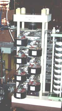
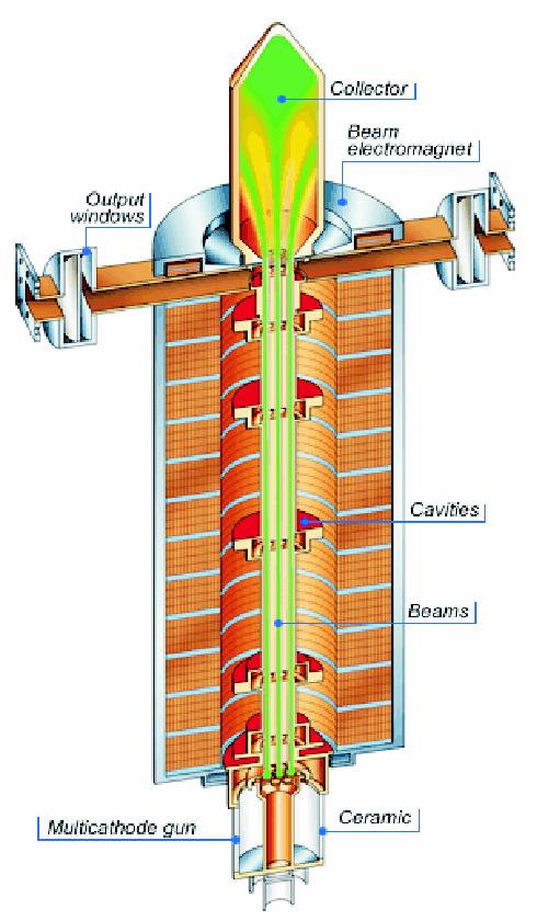
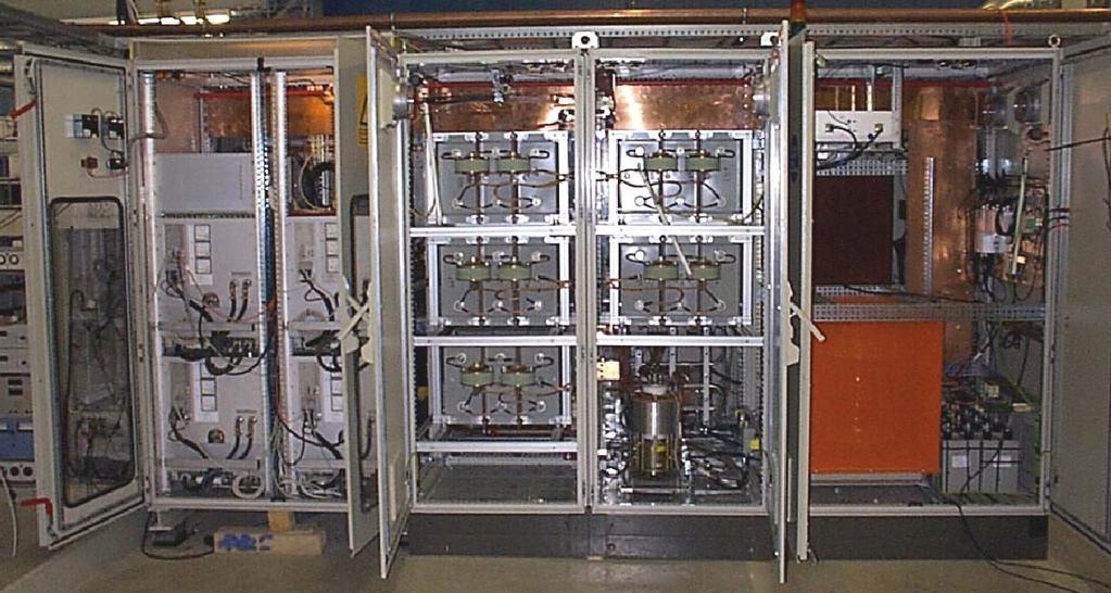
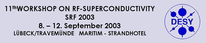
14 TTF High Power RF Pulse Transformer IGCT Stack TH1801 Multi-Beam Klystron HV Power Supply Capacitor Bank Bouncer


15 TESLA Test Facility Linac as Prototype for the XFEL Injector ACC5 ACC4 BC3 ACC3 ACC2 BC2 ACC1 e - beam RF-GUN 500 MeV
16 Party Line Towards Full Project Specification: what we will not do Go from pulsed linac to CW operation as baseline design 20 GeV linac would require cryogenic plant ~3 times the capacity of entire 500 GeV LC He distribution would have to be drastically modified Concepts exist, but to date CW beam source is not available Develop 17m module with superstructures Relation between R&D effort and gain in fill factor is not reasonable for a ~1.5 km long linac Cost saving on RF couplers must be balanced against investment in cavity treatment infrastructure and time delay for acc. module specification Maintain the common LC and FEL site No green light from government for an LC site near Hamburg at this point in time; process in international community towards LC technology decision, international funding and site decision likely to take several years Synergy / cost saving arguments for Ellerhoop site can t be used anymore to push the plan approval procedure through
17 Party Line Towards Full Project Specification: what we should do: cost analysis Example: Klystrons / RF stations To meet reference parameters, in principle 5MW klystrons are sufficient potential cost saving on R&D and final investment Alternative: Keep the 10MW MBK, but reduce # of RF stations Model for (crude) estimate scaled from TDR-update cost figures: 0.9 M per 12m accelerator module 1.8 M per 10MW RF station driving 36 cavities Assume 75% of RF cost # of klystrons, 25% # of cavities Compare two options: (1) 6 modules/klystron and (2) 8 modules per klystron (3) with reference 4 modules per klystron somewhat surprising result, reason being inevitable need for reserve stations (1) and (2) are cheaper than (3) but also (1) is cheaper than (2)

18 Parameter Flexibility User requirements still need to be reviewed / discussed, but one trend seems to go towards flexibility in beam timing Structure. Single bunches. Few bunches. Long trains. Sub-trains with variable distance / bunch number. The s.c. linac will take care of it. But: Duty cycle, i.e. Impact on RF Gun Repetition Rate??? laser RF & LLRF cryogenics
19 Duty cycle limitations: Cryogenics LC TDR layout for module / He distribution allows for an upgrade to 800 GeV ( He Gas Return Pipe, pressure drop) At ~23 MV/m, the 1.5km linac (2.5 GeV 20 GeV) could be operated up to about 20 Hz rep rate (~2% duty cycle) Required cryogenic plant would have approximately the size of one of the six TESLA-500 LC plants From cryogenics point of view, one could use the scaling law duty cycle 1/energy 2
20 Duty cycle limitations: RF system present design of modulator / klystron station can operate at max. 10 Hz, 10MW, 1.4ms pulse length, 65% max. efficiency (average power into klystron ~220kW) Higher duty cycle at lower peak power possible average power into klystron gun is kept 220 kw (careful: DC RF efficiency drops at lower power!) concerns: IGCTs at high rep rate, RF drive power Scale beam pulse current with acc. gradient (i.e. energy) the loaded Q ext remains constant or optimize for constant beam current which requires a variable Q ext
21 Max rep. rate and beam power, 4 vs. 6 modules / klystron Calculation includes klystron efficiency, scale beam current during macro pulse with gradient, and aims for maximum possible beam power. rep rate vs. acc gradient, 4 modules/klystron rep rate vs. acc gradient, 6 modules/klystron f_rep [Hz] f_rep <P_beam>/kW f_rep [Hz] f_rep <P_beam>/kW E_acc [MV/m] E_acc [MV/m] R. Brinkmann R. Brinkmann because of beam dump (solid absorber) we wanted to limit P av 600kW
22 Variable Q ext (I beam = const.) 6 modules / klystron Keep I beam = 5 ma constant, scale Q ext E acc Attractive option: shorter pulses / higher f rep (RF gun!) rep.rate and max.average power vs. acc.gradient Q ext varied with E acc (I beam = const.) 6 modules / klystron 1.6 for this example: assumed variation of pulse length vs. E acc f_rep [Hz] f_rep <P_beam>/kW E_acc [MV/m] T_pulse [ms] E_acc [MV/m] T_pulse T_beam R. Brinkmann R. Brinkmann Q ext = Q ext = Too high rep.frequencies might cause problems with the RF gun!
23 Injector and low-energy linac section Possibility of RF gun operation at 50Hz or more has to be studied. Pulse shortening likely to help! 500 MeV injector can t be scaled in E acc for higher f rep (bunch compression, beam dynamics) special solution for RF system desirable (lower power/higher duty cycle klystrons?) GeV linac section (before BC-III): To which extend can we change the energy in BC-III? If constant energy at BC-III is necessary then the 2 GeV prelinac needs a modified layout (rf system, reduced gradient?).
24 Prepare for Start of Project Construction The XFEL Project Group structures the work necessary to prepare for start of project construction in ~ two years. A total of 38 work packages was created. WPs cover different categories for complete project definition: Overall design & parameters, beam physics Major technical components Sub-systems Other issues WPs are not orthogonal good communication / interaction necessary. All WPs have one DESY representative. This does not mean to imply that DESY wants to take over all tasks! Leadership and / or participation from other labs is already present, especially for s.c.linac technology, e.g. C. Pagani / INFN & TESLA Coll.Leader (acc. module development) T. Garvey / Orsay et al. (RF couplers) C. Magne / Saclay et al. (linac BPMs) Participation from outside will grow in the future. Partners will be integrated in the XFEL Project Group as early as possible.
25 XFEL Project Group: 38 work packages accelerator modules module test / magnets / cryogenics linac components (injector, bunch compressors, diagnostics, dumps) Photons FEL concepts Controls / Operability Infrastructure (site, civil construction, survey, tunnel layout, utilities) Safety Organisation
26 XFEL Project Group: 38 work packages accelerator modules module test / magnets / cryogenics linac components (injector, bunch compressors, diagnostics, dumps) Photons FEL concepts Controls / Operability Infrastructure (site, civil construction, survey, tunnel layout, utilities) Safety Organisation
27 XFEL Project Group: 38 work packages accelerator modules module test / magnets / cryogenics linac components (injector, bunch compressors, diagnostics, dumps) Photons FEL concepts Controls / Operability Infrastructure (site, civil construction, survey, tunnel layout, utilities) Safety Organisation
 Photons FEL concepts Controls / Operability Infrastructure (site, civil construction, survey, tunnel layout, utilities) Safety")
28 XFEL Project Group: 38 work packages accelerator modules module test / magnets / cryogenics linac components (injector, bunch compressors, diagnostics, dumps) Photons FEL concepts Controls / Operability Infrastructure (site, civil construction, survey, tunnel layout, utilities) Safety Organisation

29 If you are curious please check want to participate
30 end of slide view
31 Work Packages for the XFEL Project Aug 20 th, 2003 Draft 3.5 Work Package Suggested DESY Coordinator Comments (not exhaustive) 1. RF System S. Choroba Cost-optimized and still flexible (rep. rate) system: 10MW MBK final decision or alternatives? Design + tests necessary for modulator at high frep? Concept for fast Klystron Exchange? 2. Low Level RF (LLRF) S. Simrock # cavities per Klystron? Electronics in tunnel (radiation)? Handling of non-uniform bunch trains? Intra-train energy scan? Conventional timing issues 3. Accelerator Modules R. Lange Module assembly w/o tuner&coupler; start with assembled string and finish with module installation Weld connections Alignment inside modules Transportation Safety issues Material specifications Define processes for integration/assembly Magnetic shielding/ Demagnetization Sensors Define processes for integration/assembly Survey Pre-Alignment of cavities and coupler position 1
32 Work Package Suggested DESY Coordinator Comments (not exhaustive) 4. S.C. Cavities W. Singer Cavity baking in-situ EP on cavities with tank Determination of electrical axis of cavity Check mechanical properties of niobium after 800C Define processes of cavity preparation and assembly Optimum EP parameters First 10 nine cell-preparations after EP + 800C + bake Material EP on half cells, dumb-bells Inter-cavity spacing Optimum stress annealing + hydrogen degassing temperature ( C) Other cleaning techniques: Oxipolishing, BCP 1:1:10, etc Development of CO2 cleaning Cavity Production 5. Power Coupler W.D. Möller Alignment of coupler bellows Define processes for integration/assembly Define detailed specification for coupler Processing procedure Fixed or tuning of the coupler Define sensors needed Interlock electronics 6. HOM Coupler / Pick-Up J. Sekutowicz TW absorber Define detailed specification for HOMs Define processes for assembly Improved existing HOM coupler Define detailed specification for pick-ups Define processes for integration/assembly Cavity HOM loads at 70K? Integrate antenna in feedthrough 7. Frequency Tuner L. Lilje Define detailed specification for tuner Define processes for integration/assembly Piezo mechanical design 8. Cavity Flanges / Cold Vacuum (incl. K. Zapfe. Define detailed specification for flanges warm injector section) Define processes for integration/assembly Investigate/ Improve existing design for TTF2 Type of bellows Number of bellows Number and design of gate valves development of new flange design Welded or flanged design? Where? 2
33 Work Package Suggested DESY Coordinator Comments (not exhaustive) 9. Cavity String Assembly / Clean A. Matheisen Define processes for integration/assembly Room Quality Assurance QC of Infrastructure (Clean room, Water supply, Chemistry, EP) Define processes for clean room procedures QC of flange assembly High pressure rinsing: Online measurement of particles; TOC?, resistivity? Database / EDMS 10. Module Test Facility B. Petersen Module test stand 11. Cold Magnets H. Brück 2K Quadrupole Measurement of mechanical vibrations 12. Warm Magnets K. Sinram Design of all warm magnets for the entire machine Production or contact to production sites 13. Cryogenics B. Petersen Use of HERA plant? Separate injector/main linac systems? Cost aspect: start small, upgrade later? 14. Injector K. Flöttmann Long. internal bunch structure? Cavity tilts/coupler kicks? Bunch parameter space: low eps w. low charge/higher compression (or vice versa)? Rep. rate and duty cycle? 15. Bunch Compression and Start-to- End Simulation T. Limberg Compressors: parameter space: lower charge/higher compression (or vice versa)? Sensitivity of bunch shape/structure vs. charge, phase, etc. fluctuations? Energy at BC-III variable (at BC-II??) impact on energy vs. rep rate issue? FODO-type stage desirable (possible)? Switch yard Collimators Incorporation of FEL/SASE processes (undulators) 16. Lattice Design and Beam W. Decking Main linac and BC matching Optics/Dynamics Orbit correction & beam-based methods Collimation and diagnostic section Beam transport and distribution to user beam lines Orbit stability/stabilisation (slow and fast feedback) Lattice in undulator systems, phase shifters, correctors, matching sections Transfer to dump 17. Standard Beam Diagnostics D. Nölle BPMs Screen monitors Beam intensity and loss monitors 18. Special Beam Diagnostics H. Schlarb Slice Parameters and longitudinal phase space diagnostics Sub-picosecond timing and synchronization Other specialized devices 3
34 Work Package Suggested DESY Coordinator Comments (not exhaustive) 19. Vacuum system (warm) M. Seidel Warm beam pipe distribution starting from switch yard Bunch compressors Undulator vacuum Exit chambers to beam dumps Exit windows 20. Beam Dumps M. Schmitz Modifications to adapt to new site? Else? 21. Undulators N.N. SASE, spontaneous, helical Design Mass production preparation 22. Generic Hard Photon Beam Line N.N. High resolution monochromators Mirrors and gratings Slits and absorbers Photon diagnostics Beam splitters Extreme focussing devices Vacuum system Control systems 23. Generic Medium Energy Photon N.N. See above Beam Line 24. Photon Diagnostics K. Tiedtke Diagnostics for the photon beam quality Feedback to electron beam preparation and steering Undulator tuning 25. Experimental Areas T. Tschentscher Details according to coherence, ultra short, diffraction etc. Lasers DAQ other than Control; Systems? Control systems 26. Detector Development N.N. Development of instrumentation and analysis tools for the XFEL physics experiments 27. FEL Concepts B. Faatz Transportation of general theoretical developments in the area of FEL physics into the XFEL project Coordination of review of present FEL concepts Seeding options (coherent seeding, time slicing,?) 4
35 Work Package Suggested DESY Coordinator Comments (not exhaustive) 28. Control Systems K. Rehlich Conventional timing issues Overall slow control for the entire machine Automatic procedures (e.g. beam based corrections, failure recovery) Data analysis software Files systems and databases User interfaces 29. Operability/Failure Handling M. Minty Assess technical risks from component failures Mean time to restart of user operation after failure of various components Single/two tunnel argumentation Maximize reliability aspects 30. Ground Motion and Mechanical N.N. Monitoring of ground motion and vibrations Stability Damping measures 31. Site and Civil Construction L Hänisch Evaluation of the two (?) DESY-near sites Civil construction Tunnels Switch yard Experimental hall and other buildings Access shafts 32. Survey and Alignment J. Prenting Survey and alignment issues, implementations, implications 33. Tunnel installation K. Sinram Layout Placement of components Support structures Transport system 34. Utilities J-P Jensen Power distribution power supplies Water cooling, compressed air Integration of existing utilities Ventilation and air conditioning Temperature stabilisation Industry-type controls for utilities 35. Radiation Safety N. Tesch Analysis of radiation safety issues Implementation of radiation safety procedures and techniques Interlocks Construction plan approval issues 5
36 Work Package Suggested DESY Coordinator Comments (not exhaustive) 36. General Safety B. Zimmermann Analysis of general safety issues Implementation of general safety procedures and techniques Electrical safety Procedures 37. Construction Plan Approval N.N. Preparation of all material for construction Plan approval procedure Procedure Organization of plan approval issues Discussion with the public Legal procedures Etc. 38. Overall Project Progress Tracking R. Wichmann Organization and implementation of common tools for progress tracking Time schedule follow-up Cost to completion follow-up Configuration control Documentation Expenditure planning Work breakdown structure at higher levels 6
5 Project Costs and Schedule
 93 5 Project Costs and Schedule 5.1 Overview The cost evaluation for the integrated version of the XFEL with 30 experiments and 35 GeV beam energy as described in the TDR-2001 yielded 673 million EUR for
Experience with the Cornell ERL Injector SRF Cryomodule during High Beam Current Operation
 Experience with the Cornell ERL Injector SRF Cryomodule during High Beam Current Operation Matthias Liepe Assistant Professor of Physics Cornell University Experience with the Cornell ERL Injector SRF
3 cerl. 3-1 cerl Overview. 3-2 High-brightness DC Photocathode Gun and Gun Test Beamline
 3 cerl 3-1 cerl Overview As described before, the aim of the cerl in the R&D program includes the development of critical components for the ERL, as well as the construction of a test accelerator. The
Nick Walker DESY MAC
 Nick Walker DESY MAC 4.5.2006 XFEL X-Ray Free-Electron Laser DESY ILC Project Group Accelerator Experimentation Behnke, Elsen, Walker (chair) WP 15, 16 WP 4-7 Accelerator Physics and Design WP 6 High Gradient
TTF / VUV-FEL. Schedule 2005 and Project Management Issues. Schedule 2005 Project Organisation Budget & Controlling
 TTF / VUV-FEL Schedule 200 and Project Management Issues Schedule 200 Project Organisation Budget & Controlling Hans Weise / DESY DESY MAC Meeting November 9th, 2004 TTF Linac Start-up After Final Installation
RF considerations for SwissFEL
 RF considerations for H. Fitze in behalf of the PSI RF group Workshop on Compact X-Ray Free Electron Lasers 19.-21. July 2010, Shanghai Agenda Introduction RF-Gun Development C-band development Summary
STATUS OF THE EUROPEAN XFEL CONSTRUCTING THE 17.5 GEV SUPERCONDUCTING LINEAR ACCELERATOR
 STATUS OF THE EUROPEAN XFEL CONSTRUCTING THE 17.5 GEV SUPERCONDUCTING LINEAR ACCELERATOR Winfried Decking, DESY for the European XFEL Accelerator Consortium Up to 17.5 GeV SC Linac, 27000 pulses per second
INFN School on Electron Accelerators. RF Power Sources and Distribution
 INFN School on Electron Accelerators 12-14 September 2007, INFN Sezione di Pisa Lecture 7b RF Power Sources and Distribution Carlo Pagani University of Milano INFN Milano-LASA & GDE The ILC Double Tunnel
Summary of the 1 st Beam Line Review Meeting Injector ( )
") Summary of the 1 st Beam Line Review Meeting Injector (23.10.2006) 15.11.2006 Review the status of: beam dynamics understanding and simulations completeness of beam line description conceptual design of
Summary of the 1 st Beam Line Review Meeting Injector (23.10.2006) 15.11.2006 Review the status of: beam dynamics understanding and simulations completeness of beam line description conceptual design of
TITLE PAGE. Title of paper: PUSH-PULL FEL, A NEW ERL CONCEPT Author: Andrew Hutton. Author Affiliation: Jefferson Lab. Requested Proceedings:
 TITLE PAGE Title of paper: PUSH-PULL FEL, A NEW ERL CONCEPT Author: Andrew Hutton Author Affiliation: Jefferson Lab Requested Proceedings: Unique Session ID: Classification Codes: Keywords: Energy Recovery,
Current status of XFEL/SPring-8 project and SCSS test accelerator
 Current status of XFEL/SPring-8 project and SCSS test accelerator Takahiro Inagaki for XFEL project in SPring-8 inagaki@spring8.or.jp Outline (1) Introduction (2) Key technology for compactness (3) Key
SUMMARY OF THE ILC R&D AND DESIGN
 SUMMARY OF THE ILC R&D AND DESIGN B. C. Barish, California Institute of Technology, USA Abstract The International Linear Collider (ILC) is a linear electron-positron collider based on 1.3 GHz superconducting
2 Work Package and Work Unit descriptions. 2.8 WP8: RF Systems (R. Ruber, Uppsala)
") 2 Work Package and Work Unit descriptions 2.8 WP8: RF Systems (R. Ruber, Uppsala) The RF systems work package (WP) addresses the design and development of the RF power generation, control and distribution
2 Work Package and Work Unit descriptions 2.8 WP8: RF Systems (R. Ruber, Uppsala) The RF systems work package (WP) addresses the design and development of the RF power generation, control and distribution
Digital BPMs and Orbit Feedback Systems
 Digital BPMs and Orbit Feedback Systems, M. Böge, M. Dehler, B. Keil, P. Pollet, V. Schlott Outline stability requirements at SLS storage ring digital beam position monitors (DBPM) SLS global fast orbit
WG2 Group Summary. Chris Adolphsen Terry Garvey Hitoshi Hayano
 WG2 Group Summary Chris Adolphsen Terry Garvey Hitoshi Hayano Linac Options Fest On Thursday afternoon, various experts summarized the linac baseline options. Although hard choices have yet to be made,
CLIC Feasibility Demonstration at CTF3
 CLIC Feasibility Demonstration at CTF3 Roger Ruber Uppsala University, Sweden, for the CLIC/CTF3 Collaboration http://cern.ch/clic-study LINAC 10 MO303 13 Sep 2010 The Key to CLIC Efficiency NC Linac for
Detailed Design Report
 Detailed Design Report Chapter 4 MAX IV Injector 4.6. Acceleration MAX IV Facility CHAPTER 4.6. ACCELERATION 1(10) 4.6. Acceleration 4.6. Acceleration...2 4.6.1. RF Units... 2 4.6.2. Accelerator Units...
STATUS OF THE EUROPEAN XFEL
 STATUS OF THE EUROPEAN XFEL M. Hüning, DESY, Hamburg, Germany for the European XFEL Accelerator Construction Consortium * Abstract The European XFEL is one of the world's largest accelerators presently
STATUS OF THE SWISSFEL C-BAND LINEAR ACCELERATOR
 Proceedings of FEL213, New York, NY, USA STATUS OF THE SWISSFEL C-BAND LINEAR ACCELERATOR F. Loehl, J. Alex, H. Blumer, M. Bopp, H. Braun, A. Citterio, U. Ellenberger, H. Fitze, H. Joehri, T. Kleeb, L.
Design Studies For The LCLS 120 Hz RF Gun Injector
 BNL-67922 Informal Report LCLS-TN-01-3 Design Studies For The LCLS 120 Hz RF Gun Injector X.J. Wang, M. Babzien, I. Ben-Zvi, X.Y. Chang, S. Pjerov, and M. Woodle National Synchrotron Light Source Brookhaven
Present Status and Future Upgrade of KEKB Injector Linac
 Present Status and Future Upgrade of KEKB Injector Linac Kazuro Furukawa, for e /e + Linac Group Present Status Upgrade in the Near Future R&D towards SuperKEKB 1 Machine Features Present Status and Future
LLRF at SSRF. Yubin Zhao
 LLRF at SSRF Yubin Zhao 2017.10.16 contents SSRF RF operation status Proton therapy LLRF Third harmonic cavity LLRF Three LINAC LLRF Hard X FEL LLRF (future project ) Trip statistics of RF system Trip
30 GHz Power Production / Beam Line
 30 GHz Power Production / Beam Line Motivation & Requirements Layout Power mode operation vs. nominal parameters Beam optics Achieved performance Problems Beam phase switch for 30 GHz pulse compression
ILC-LNF TECHNICAL NOTE
 IL-LNF EHNIAL NOE Divisione Acceleratori Frascati, July 4, 2006 Note: IL-LNF-001 RF SYSEM FOR HE IL DAMPING RINGS R. Boni, INFN-LNF, Frascati, Italy G. avallari, ERN, Geneva, Switzerland Introduction For
High Brightness Injector Development and ERL Planning at Cornell. Charlie Sinclair Cornell University Laboratory for Elementary-Particle Physics
 High Brightness Injector Development and ERL Planning at Cornell Charlie Sinclair Cornell University Laboratory for Elementary-Particle Physics June 22, 2006 JLab CASA Seminar 2 Background During 2000-2001,
Accelerator Instrumentation RD. Monday, July 14, 2003 Marc Ross
 Monday, Marc Ross Linear Collider RD Most RD funds address the most serious cost driver energy The most serious impact of the late technology choice is the failure to adequately address luminosity RD issues
The FLASH objective: SASE between 60 and 13 nm
 Injector beam control studies winter 2006/07 talk from E. Vogel on work performed by W. Cichalewski, C. Gerth, W. Jalmuzna,W. Koprek, F. Löhl, D. Noelle, P. Pucyk, H. Schlarb, T. Traber, E. Vogel, FLASH
Status of CTF3. G.Geschonke CERN, AB
 Status of CTF3 G.Geschonke CERN, AB CTF3 layout CTF3 - Test of Drive Beam Generation, Acceleration & RF Multiplication by a factor 10 Drive Beam Injector ~ 50 m 3.5 A - 2100 b of 2.33 nc 150 MeV - 1.4
XFEL High Power RF System Recent Developments
 XFEL High Power RF System Recent Developments for the XFEL RF Group Outline XFEL RF System Requirements Overview Basic Layout RF System Main Components Multibeam Klystrons Modulator RF Waveguide Distribution
The Elettra Storage Ring and Top-Up Operation
 The Elettra Storage Ring and Top-Up Operation Emanuel Karantzoulis Past and Present Configurations 1994-2007 From 2008 5000 hours /year to the users 2010: Operations transition year Decay mode, 2 GeV (340mA)
LCLS RF Reference and Control R. Akre Last Update Sector 0 RF and Timing Systems
 LCLS RF Reference and Control R. Akre Last Update 5-19-04 Sector 0 RF and Timing Systems The reference system for the RF and timing starts at the 476MHz Master Oscillator, figure 1. Figure 1. Front end
Oak Ridge Spallation Neutron Source Proton Power Upgrade Project and Second Target Station Project
 Oak Ridge Spallation Neutron Source Proton Power Upgrade Project and Second Target Station Project Workshop on the future and next generation capabilities of accelerator driven neutron and muon sources
The TESLA RF System. S. Choroba. for the TESLA Collaboration. DESY Notkestr. 85, D Hamburg, Germany
 The TESLA RF System S. Choroba for the TESLA Collaboration DESY Notkestr. 85, D-22603 Hamburg, Germany Abstract. The TESLA project proposed by the TESLA collaboration in 2001 is a 500 to 800GeV e+/e- linear
Suggested ILC Beam Parameter Range Rev. 2/28/05 Tor Raubenheimer
 The machine parameters and the luminosity goals of the ILC were discussed at the 1 st ILC Workshop. In particular, Nick Walker noted that the TESLA machine parameters had been chosen to achieve a high
SPEAR 3: Operations Update and Impact of Top-Off Injection
 SPEAR 3: Operations Update and Impact of Top-Off Injection R. Hettel for the SSRL ASD 2005 SSRL Users Meeting October 18, 2005 SPEAR 3 Operations Update and Development Plans Highlights of 2005 SPEAR 3
Status of BESSY II and berlinpro. Wolfgang Anders. Helmholtz-Zentrum Berlin for Materials and Energy (HZB) 20th ESLS-RF Meeting
 20th ESLS-RF Meeting") Status of BESSY II and berlinpro Wolfgang Anders Helmholtz-Zentrum Berlin for Materials and Energy (HZB) 20th ESLS-RF Meeting 16.-17.11.2016 at PSI Outline BESSY II Problems with circulators Landau cavity
Status of BESSY II and berlinpro Wolfgang Anders Helmholtz-Zentrum Berlin for Materials and Energy (HZB) 20th ESLS-RF Meeting 16.-17.11.2016 at PSI Outline BESSY II Problems with circulators Landau cavity
Status of JRA-SRF in CARE
 Status of JRA-SRF in CARE Reminder JRA-SRF: Strategy, Partner, financial volume Where do we stand in JRA-SRF today Progress in work-packages, schedule Administrative & financial issues What is next First
Availability and Reliability Issues for the ILC
 Availability and Reliability Issues for the ILC SLAC Presented at PAC07 26 June 07 Contents Introduction and purpose of studies The availability simulation What was modeled (important assumptions) Some
P. Emma, et al. LCLS Operations Lectures
 P. Emma, et al. LCLS Operations Lectures LCLS 1 LCLS Accelerator Schematic 6 MeV 135 MeV 250 MeV σ z 0.83 mm σ z 0.83 mm σ z 0.19 mm σ δ 0.05 % σ δ 0.10 % σ δ 1.6 % Linac-0 L =6 m rf gun L0-a,b Linac-1
Activities on FEL Development and Application at Kyoto University
 Activities on FEL Development and Application at Kyoto University China-Korea-Japan Joint Workshop on Electron / Photon Sources and Applications Dec. 2-3, 2010 @ SINAP, Shanghai Kai Masuda Inst. Advanced
The ESS Accelerator. For Norwegian Industry and Research. Oslo, 24 Sept Håkan Danared Deputy Head Accelerator Division Group Leader Beam Physics
 The ESS Accelerator For Norwegian Industry and Research Oslo, 24 Sept 2013 Håkan Danared Deputy Head Accelerator Division Group Leader Beam Physics The Hadron Intensity Frontier Courtesy of M. Seidel (PSI)
PEP II Design Outline
 PEP II Design Outline Balša Terzić Jefferson Lab Collider Review Retreat, February 24, 2010 Outline General Information Parameter list (and evolution), initial design, upgrades Collider Ring Layout, insertions,
A HIGH POWER LONG PULSE HIGH EFFICIENCY MULTI BEAM KLYSTRON
 A HIGH POWER LONG PULSE HIGH EFFICIENCY MULTI BEAM KLYSTRON A.Beunas and G. Faillon Thales Electron Devices, Vélizy, France S. Choroba DESY, Hamburg, Germany Abstract THALES ELECTRON DEVICES has developed
The PEFP 20-MeV Proton Linear Accelerator
 Journal of the Korean Physical Society, Vol. 52, No. 3, March 2008, pp. 721726 Review Articles The PEFP 20-MeV Proton Linear Accelerator Y. S. Cho, H. J. Kwon, J. H. Jang, H. S. Kim, K. T. Seol, D. I.
AREAL- Phase 1. B. Grigoryan on behalf of AREAL team
 AREAL- Phase 1 Progress & Status B. Grigoryan on behalf of AREAL team Contents Machine Layout Building & Infrastructure Laser System RF System Vacuum System Cooling System Control System Beam Diagnostics
Diamond RF Status (RF Activities at Daresbury) Mike Dykes
 Mike Dykes") Diamond RF Status (RF Activities at Daresbury) Mike Dykes ASTeC What is it? What does it do? Diamond Status Linac Booster RF Storage Ring RF Summary Content ASTeC ASTeC was formed in 2001 as a centre of
Diamond RF Status (RF Activities at Daresbury) Mike Dykes ASTeC What is it? What does it do? Diamond Status Linac Booster RF Storage Ring RF Summary Content ASTeC ASTeC was formed in 2001 as a centre of
L-Band RF R&D. SLAC DOE Review June 15 th, Chris Adolphsen SLAC
 L-Band RF R&D SLAC DOE Review June 15 th, 2005 Chris Adolphsen SLAC International Linear Collider (ILC) RF Unit (TESLA TDR Layout) Gradient = 23.4 MV/m Bunch Spacing = 337 ns Fill Time = 420 µs Train Length
!"!3
 Abstract A single-mode 500 MHz superconducting cavity cryomodule has been developed at Cornell for the electronpositron collider/synchrotron light source CESR. The Cornell B-cell cavity belongs to the
Upgrading LHC Luminosity
 1 Upgrading LHC Luminosity 2 Luminosity (cm -2 s -1 ) Present (2011) ~2 x10 33 Beam intensity @ injection (*) Nominal (2015?) 1 x 10 34 1.1 x10 11 Upgraded (2021?) ~5 x10 34 ~2.4 x10 11 (*) protons per
Review Meeting on on the TESLA Test Facility Phase 2 Summary Hans Weise for the Meeting Participants. Hans Weise
 Review Meeting on on the TESLA Test Facility Phase 2 Summary Hans Weise for the Meeting Participants Hans Weise Hans Weise 250 kv thermionic gun TTF1 - Some Historical Remarks 4 accelerator modules beam
Future Performance of the LCLS
 Future Performance of the LCLS J. Welch for many* SLAC National Accelerator Laboratory FLS 2010, ICFA Beam Dynamics Workshop on Future Light Sources, March 1-5, 2010. SLAC National Accelerator Laboratory,
STATUS OF THE INTERNATIONAL LINEAR COLLIDER
 STATUS OF THE INTERNATIONAL LINEAR COLLIDER K. Yokoya, KEK, Tsukuba, Japan Abstract The International Linear Collider (ILC) is the nextgeneration electron-positron collider. Since the publication of the
TTF2 (TESLA Test Facility, Phase 2) VUV FEL (Vacuum-Ultraviolet Free-Electron Laser)
 VUV FEL (Vacuum-Ultraviolet Free-Electron Laser)") DESY MAC Meeting 9. Nov. 2004 TTF2 (TESLA Test Facility, Phase 2) VUV FEL (Vacuum-Ultraviolet Free-Electron Laser) Overview and Status Jörg Rossbach 1 Overview BC 3 BC 2 Injector 3 LOLA 260 m 2 TTF External
DESY MAC Meeting 9. Nov. 2004 TTF2 (TESLA Test Facility, Phase 2) VUV FEL (Vacuum-Ultraviolet Free-Electron Laser) Overview and Status Jörg Rossbach 1 Overview BC 3 BC 2 Injector 3 LOLA 260 m 2 TTF External
IOT OPERATIONAL EXPERIENCE ON ALICE AND EMMA AT DARESBURY LABORATORY
 IOT OPERATIONAL EXPERIENCE ON ALICE AND EMMA AT DARESBURY LABORATORY A. Wheelhouse ASTeC, STFC Daresbury Laboratory ESLS XVIII Workshop, ELLETRA 25 th 26 th November 2010 Contents Brief Description ALICE
Simulations on Beam Monitor Systems for Longitudinal Feedback Schemes at FLASH.
 Simulations on Beam Monitor Systems for Longitudinal Feedback Schemes at FLASH. Christopher Behrens for the FLASH team Deutsches Elektronen-Synchrotron (DESY) FLS-2010 Workshop at SLAC, 4. March 2010 C.
New Filling Pattern for SLS-FEMTO
 SLS-TME-TA-2009-0317 July 14, 2009 New Filling Pattern for SLS-FEMTO Natalia Prado de Abreu, Paul Beaud, Gerhard Ingold and Andreas Streun Paul Scherrer Institut, CH-5232 Villigen PSI, Switzerland A new
DESIGN OF 1.2-GEV SCL AS NEW INJECTOR FOR THE BNL AGS*
 DESIGN OF 1.2-GEV SCL AS NEW INJECTOR FOR THE BNL AGS* A. G. Ruggiero, J. Alessi, M. Harrison, M. Iarocci, T. Nehring, D. Raparia, T. Roser, J. Tuozzolo, W. Weng. Brookhaven National Laboratory, PO Box
Photo cathode RF gun -
 Photo cathode RF gun - *),,, ( 05 Nov. 2004 Spring8 UTNL Linac & Mg Photocathode RF Gun Mg photocathode NERL, 18 MeV Linac and the RF gun Electron Beam Mg photocathode Mg photocathode RF gun of SPring8
ESS: The Machine. Bucharest, 24 April Håkan Danared Deputy Head Accelerator Division. H. Danared Industry & Partner Days Bucharest Page 1
 ESS: The Machine Bucharest, 24 April 2014 Håkan Danared Deputy Head Accelerator Division H. Danared Industry & Partner Days Bucharest Page 1 2025 ESS construction complete 2009 Decision: ESS will be built
Next Linear Collider. The 8-Pack Project. 8-Pack Project. Four 50 MW XL4 X-band klystrons installed on the 8-Pack
 The Four 50 MW XL4 X-band klystrons installed on the 8-Pack The Demonstrate an NLC power source Two Phases: 8-Pack Phase-1 (current): Multi-moded SLED II power compression Produce NLC baseline power: 475
RUNNING EXPERIENCE OF FZD SRF PHOTOINJECTOR
 RUNNING EXPERIENCE OF FZD SRF PHOTOINJECTOR Rong Xiang On behalf of the BESSY-DESY-FZD-MBI collaboration and the ELBE team FEL 2009, Liverpool, United Kingdom, August 23 ~ 28, 2009 Outline Introduction
Cathode Studies at FLASH: CW and Pulsed QE measurements
 Cathode Studies at FLASH: CW and Pulsed QE measurements L. Monaco, D. Sertore, P. Michelato S. Lederer, S. Schreiber Work supported by the European Community (contract number RII3-CT-2004-506008) 1/27
Technical Document 1 attached to the European XFEL Convention
 May 30, 2007 Technical Document 1 attached to the European XFEL Convention Executive Summary of the Technical Design Report (Part A) and Scenario for the Rapid Start-up of the European XFEL Facility (Part
TTF Tuner Development: Saclay and INFN-Blade
 TTF Tuner Development: Saclay and INFN-Blade Carlo Pagani INFN Milano and DESY On leave from University of Milano The TTF Saclay Tuner: Operation Principle Design by M. Maurier and P. Leconte based of
ESS Linac WP8 Radio Frequency Systems and Test Facilities
 ESS Linac WP8 Radio Frequency Systems and Test Facilities ESS/SPL Collaboration Meeting Lund, 29 June 2010 Roger Ruber (Uppsala University) for the ESS Linac RF Team ESS Linac WP8: RF Systems Outline Work
TWO BUNCHES WITH NS-SEPARATION WITH LCLS*
 TWO BUNCHES WITH NS-SEPARATION WITH LCLS* F.-J. Decker, S. Gilevich, Z. Huang, H. Loos, A. Marinelli, C.A. Stan, J.L. Turner, Z. van Hoover, S. Vetter, SLAC, Menlo Park, CA 94025, USA Abstract The Linac
The LEP Superconducting RF System
 The LEP Superconducting RF System K. Hübner* for the LEP RF Group CERN The basic components and the layout of the LEP rf system for the year 2000 are presented. The superconducting system consisted of
North Damping Ring RF
 North Damping Ring RF North Damping Ring RF Outline Overview High Power RF HVPS Klystron & Klystron EPICS controls Cavities & Cavity Feedback SCP diagnostics & displays FACET-specific LLRF LLRF distribution
Report on the LCLS Injector Technical Review
 Report on the LCLS Injector Technical Review Stanford Linear Accelerator Center November 3&4, 2003 Committee Members Prof. Patrick G. O Shea, Chair, University of Maryland Dr. Eric Colby, Stanford Linear
Upgrade of CEBAF to 12 GeV
 Upgrade of CEBAF to 12 GeV Leigh Harwood (for 12 GeV Accelerator team) Page 1 Outline Background High-level description Schedule Sub-system descriptions and status Summary Page 2 CEBAF Science Mission
4.4 Injector Linear Accelerator
 4.4 Injector Linear Accelerator 100 MeV S-band linear accelerator based on the components already built for the S-Band Linear Collider Test Facility at DESY [1, 2] will be used as an injector for the CANDLE
SLAC ILC Accelerator R&D Program
 SLAC ILC Accelerator R&D Program SLUO Meeting September 26 th, 2005 Tor Raubenheimer SLAC 2005 ILC Program NLC group was redirected towards ILC Developed a program aimed at the topics identified in the
Proceedings of the 1997 Workshop on RF Superconductivity, Abano Terme (Padova), Italy
, Italy") BEAM RELATED THERMAL LOSSES ON THE CRYOGENIC AND VACUUM SYSTEMS OF LEP G. Cavallari, Ph. Gayet, G. Geschonke, D. Kaiser, J.M. Jimenez CERN, 111 GENEVA 3 (Switzerland) Abstract The LEP Collider was operated
BEAM RELATED THERMAL LOSSES ON THE CRYOGENIC AND VACUUM SYSTEMS OF LEP G. Cavallari, Ph. Gayet, G. Geschonke, D. Kaiser, J.M. Jimenez CERN, 111 GENEVA 3 (Switzerland) Abstract The LEP Collider was operated
Towards an X-Band Power Source at CERN and a European Structure Test Facility
 Towards an X-Band Power Source at CERN and a European Structure Test Facility Erk Jensen and Gerry McMomagle CERN The X-Band Accelerating Structure Design and Test-Program Workshop Day 2: Structure Testing
CLIC Feasibility Demonstration at CTF3
 CLIC Feasibility Demonstration at CTF3 Roger Ruber Uppsala University, Sweden, KVI Groningen 20 Sep 2011 The Key to CLIC Efficiency NC Linac for 1.5 TeV/beam accelerating gradient: 100 MV/m RF frequency:
ESS Linac WP8 Radio Frequency Systems and Test Facilities
 ESS Linac WP8 Radio Frequency Systems and Test Facilities ESS TAC Lund, 8 July 2010 Roger Ruber (Uppsala University) for the ESS Linac RF Team Outline Work Package description Objectives Organization Technical
Commissioning of Accelerators. Dr. Marc Munoz (with the help of R. Miyamoto, C. Plostinar and M. Eshraqi)
") Commissioning of Accelerators Dr. Marc Munoz (with the help of R. Miyamoto, C. Plostinar and M. Eshraqi) www.europeanspallationsource.se 6 July, 2017 Contents General points Definition of Commissioning
Commissioning of Accelerators Dr. Marc Munoz (with the help of R. Miyamoto, C. Plostinar and M. Eshraqi) www.europeanspallationsource.se 6 July, 2017 Contents General points Definition of Commissioning
DESIGN AND PERFORMANCE OF L-BAND AND S-BAND MULTI BEAM KLYSTRONS
 DESIGN AND PERFORMANCE OF L-BAND AND S-BAND MULTI BEAM KLYSTRONS Y. H. Chin, KEK, Tsukuba, Japan. Abstract Recently, there has been a rising international interest in multi-beam klystrons (MBK) in the
Photoinjector Laser Operation and Cathode Performance
 Photoinjector Laser Operation and Cathode Performance Daniele Sertore, INFN Milano LASA Siegfried Schreiber, DESY Laser operational experience Laser beam properties Cathode performances Outlook TTF and
PoS(EPS-HEP2015)525. The RF system for FCC-ee. A. Butterworth CERN 1211 Geneva 23, Switzerland
525. The RF system for FCC-ee. A. Butterworth CERN 1211 Geneva 23, Switzerland") CERN 1211 Geneva 23, Switzerland E-mail: andrew.butterworth@cern.ch O. Brunner CERN 1211 Geneva 23, Switzerland E-mail: olivier.brunner@cern.ch R. Calaga CERN 1211 Geneva 23, Switzerland E-mail: rama.calaga@cern.ch
CERN 1211 Geneva 23, Switzerland E-mail: andrew.butterworth@cern.ch O. Brunner CERN 1211 Geneva 23, Switzerland E-mail: olivier.brunner@cern.ch R. Calaga CERN 1211 Geneva 23, Switzerland E-mail: rama.calaga@cern.ch
Status of SOLARIS. Paweł Borowiec On behalf of Solaris Team
 Status of SOLARIS Paweł Borowiec On behalf of Solaris Team e-mail: pawel.borowiec@uj.edu.pl XX ESLS-RF Meeting, Villingen 16-17.11.2016 Outline 1. Timeline 2. Injector 3. Storage ring 16-17.11.2016 XX
Intra-train Longitudinal Feedback for Beam Stabilization at FLASH
 Intra-train Longitudinal Feedback for Beam Stabilization at FLASH Ch. Behrens 1), M.-K. Bock 1), M. Felber 1), P. Gessler 1), K. Hacker 1), W. Koprek 1), H. Schlarb 1), S. Wesch 1), C.Schmidt 1), S. Schulz
High Rep Rate Guns: FZD Superconducting RF Photogun
 High Rep Rate Guns: FZD Superconducting RF Photogun J. Teichert, A. Arnold, H. Büttig, D. Janssen, M. Justus, U. Lehnert, P. Michel, K. Moeller, P. Murcek, Ch. Schneider, R. Schurig, G. Staats, F. Staufenbiel,
Linac 4 Instrumentation K.Hanke CERN
 Linac 4 Instrumentation K.Hanke CERN CERN Linac 4 PS2 (2016?) SPL (2015?) Linac4 (2012) Linac4 will first inject into the PSB and then can be the first element of a new LHC injector chain. It will increase
FIRST SIMULTANEOUS TOP-UP OPERATION OF THREE DIFFERENT RINGS IN KEK INJECTOR LINAC
 FIRST SIMULTANEOUS TOP-UP OPERATION OF THREE DIFFERENT RINGS IN KEK INJECTOR LINAC M. Satoh #, for the IUC * Accelerator Laboratory, High Energy Accelerator Research Organization (KEK) 1-1 Oho, Tsukuba,
STATUS OF THE SwissFEL C-BAND LINAC
 STATUS OF THE SwissFEL C-BAND LINAC F. Loehl, J. Alex, H. Blumer, M. Bopp, H. Braun, A. Citterio, U. Ellenberger, H. Fitze, H. Joehri, T. Kleeb, L. Paly, J.-Y. Raguin, L. Schulz, R. Zennaro, C. Zumbach,
News from HZB / BESSY Wolfgang Anders at ESLS-RF Meeting September 2010 Trieste
 News from HZB / BESSY Wolfgang Anders at ESLS-RF Meeting September 2010 Trieste Outline Status Klystrons / IOT Modifications of transmitters New LINAC for BESSY II Status BERLinPro HoBiCaT Extension --
Pulsed Klystrons for Next Generation Neutron Sources Edward L. Eisen - CPI, Inc. Palo Alto, CA, USA
 Pulsed Klystrons for Next Generation Neutron Sources Edward L. Eisen - CPI, Inc. Palo Alto, CA, USA Abstract The U.S. Department of Energy (DOE) Office of Science has funded the construction of a new accelerator-based
LCLS Injector Technical Review
 LCLS Injector Technical Review Stanford Linear Accelerator Center November 3&4 2003 Review Committee Members: Prof. Patrick O Shea Chair University of Maryland Dr. E. Colby Stanford Linear Accelerator
Technology Challenges for SRF Guns as ERL Sources in View of Rossendorf work
 Technology Challenges for SRF Guns as ERL Sources in View of Rossendorf work, Hartmut Buettig, Pavel Evtushenko, Ulf Lehnert, Peter Michel, Karsten Moeller, Petr Murcek, Christof Schneider, Rico Schurig,
CLEX (CLIC Experimental Area)
") CLEX (CLIC Experimental Area) Status and plans G.Geschonke for Hans Braun CERN CT3 coll meetg 2005 CLEX 1 CT3 objectives R1.1 CLIC accelerating structure, R1.2 rive beam scheme with a fully loaded linac
CLEX (CLIC Experimental Area) Status and plans G.Geschonke for Hans Braun CERN CT3 coll meetg 2005 CLEX 1 CT3 objectives R1.1 CLIC accelerating structure, R1.2 rive beam scheme with a fully loaded linac
The basic parameters of the pre-injector are listed in the Table below. 100 MeV
 3.3 The Pre-injector The high design brightness of the SLS requires very high phase space density of the stored electrons, leading to a comparatively short lifetime of the beam in the storage ring. This,
EUROFEL-Report-2007-DS EUROPEAN FEL Design Study
 EUROFEL-Report-2007-DS4-095 EUROPEAN FEL Design Study Deliverable N : D 4.3 Deliverable Title: Task: Authors: Generation of 3rd harmonic photons at 90 nm DS-4 see next page Contract N : 011935 Project
Jae-Young Choi On behalf of PLS-II Linac team
 PLS-II Linac 2015. 4. 8. Jae-Young Choi On behalf of PLS-II Linac team Accelerators in Pohang Accelerator Laboratory XFEL (under construction) 400 M$ Machines under installation PLS-II PAL : Chronology
What can be learned from HERA Experience for ILC Availability
 What can be learned from HERA Experience for ILC Availability August 17, 2005 F. Willeke, DESY HERA Performance Critical Design Decisions What could be avoided if HERA would have to be built again? HERA
Welcome and FRIB Project Status. FRIB Highlights and Plan Ahead
 Welcome and FRIB Project Status Thomas Glasmacher Project Manager This material is based upon work supported by the U.S. Department of Energy Office of Science under Cooperative Agreement DE-SC0000661.
Pulses inside the pulse mode of operation at RF Gun
 Pulses inside the pulse mode of operation at RF Gun V. Vogel, V. Ayvazyan, K. Floettmann, D. Lipka, P. Morozov, H. Schlarb, S. Schreiber FLASH Seminar, DESY March 29, 2011 Contents Why we need a PiPmode
TESLA FEL-Report
 Determination of the Longitudinal Phase Space Distribution produced with the TTF Photo Injector M. Geitz a,s.schreiber a,g.von Walter b, D. Sertore a;1, M. Bernard c, B. Leblond c a Deutsches Elektronen-Synchrotron,
J/NLC Progress on R1 and R2 Issues. Chris Adolphsen
 J/NLC Progress on R1 and R2 Issues Chris Adolphsen Charge to the International Linear Collider Technical Review Committee (ILC-TRC) To assess the present technical status of the four LC designs at hand,
Low Level RF for PIP-II. Jonathan Edelen LLRF 2017 Workshop (Barcelona) 16 Oct 2017
 16 Oct 2017") Low Level RF for PIP-II Jonathan Edelen LLRF 2017 Workshop (Barcelona) 16 Oct 2017 PIP-II LLRF Team Fermilab Brian Chase, Edward Cullerton, Joshua Einstein, Jeremiah Holzbauer, Dan Klepec, Yuriy Pischalnikov,
Low Level RF for PIP-II Jonathan Edelen LLRF 2017 Workshop (Barcelona) 16 Oct 2017 PIP-II LLRF Team Fermilab Brian Chase, Edward Cullerton, Joshua Einstein, Jeremiah Holzbauer, Dan Klepec, Yuriy Pischalnikov,