SOFTWARE INSTALLATION...
|
|
|
- Susan Mason
- 6 years ago
- Views:
Transcription
1 MANUAL v1.08 D&R Electronica B.V., Rijnkade 15B, 1382GS Weesp, The Netherlands Phone: +31 (0) , Fax: +31 (0) , Website:
2 Contents 1 SOFTWARE INSTALLATION AIRLITE CONTROL AIRLITE METERS AIRLITE CONFIGURATION MANAGER AIRLITE VOIP FIRMWARE UPDATETOOL INTRODUCTION MIXER UNIT MIC / LINE MODULES USB / LINE MODULES VOIP/ LINE MODULE MASTER SECTION SOFTWARE SIGNAL FLOW AIRLITE BACKPANEL MASTER CONNECTORS MIC / LINE INPUT MODULES GAIN STEREO LINE MIC EQUALIZER AUX SEND CUE/COMMUNICATION BUSS ON VOICE TRACK BUSS FADER INPUT CONNECTORS INSERT MICROPHONE INPUT SPECIAL OPTIONS HOW TO REMOVE THE BOTTOM OF YOUR MIXER USB / LINE INPUT MODULES GAIN STEREO LINE USB AUX SEND CUE/COMMUNICATION BUSS ON FADER SETTING UP THE USB MODULES USB OUTPUTS SETTING UP THE MODULES VOIP / LINE INPUT MODULE WHAT IS A TELEPHONE HYBRID? VOIP CHANNEL GAIN LINE / VOIP INPUT SWITCH VOIP SEND CONNECT AUX SEND CUE ON FADER INPUT CONNECTORS MASTER SECTION LEDBAR METERS NONSTOP
3 8.3 CUE NS (NON-STOP) AUX SEND AUX RETURN CUE AIR (EXTERNAL) INPUT ANNOUNCER AUX CUE PHONES CUE RESET CRM SECTION (CONTROL ROOM MONITOR) TALKBACK TO METERING MASTER BACKPANEL CONNECTORS POWER CONNECTOR AIR INPUTS AUX SEND CRM SEND CUE (SEND) AUX RETURN MASTER (SEND) MIC ON ANOUNCER PHONES JACK MASTER OUTPUTS MASTER AES/EBU XLR CONNECTORS SET-UP ROUTINES MODULE SETTING UP AN INPUT CHANNEL SET-UP ROUTINES MODULE 8 (VOIP) SOFTWARE OVERVIEW AIRLITE CONFIGURATION MANAGER INTRODUCTION CONNECTION & SETUP COMMUNICATION MODULE SETTINGS MASTER SETTINGS READ/WRITE CONFIGURATION FROM/TO CONSOLE CONFIGURATION PRESETS AIRLITE METERS INTRODUCTION SOFTWARE ELEMENTS SETUP UNDERSTANDING INTERNET RADIO TECHNICAL SPECIFICATIONS SPECIFICATIONS DIMENSIONS SUMMARY ELECTROMAGNETIC COMPATIBILITY DECLARATION OF CONFORMITY PRODUCT SAFETY CAUTION
4 Dear Client, Thank you for choosing the D&R AIRLITE mixer. The AIRLITE was designed by Radio Broadcast professionals along with the D&R design team and is intended to be used 24 hours per day as an On-Air mixer and/or a production console in the most demanding production room. We are confident that you will be using the AIRLITE mixer for many years to come, and wish you much success. We value suggestions from our clients and would be grateful if you could us with your comments when you are familiar with the AIRLITE mixer. We learn from the ideas and suggestions of customers like you and appreciate your time taken to eventually do this. And... we always appreciate nice studio pictures with the AIRLITE in use to include on our website. Please mail them to mail@d-r.nl With kind regards, Duco de Rijk MD 4
5 1 SOFTWARE INSTALLATION 1) Download the latest software and/or firmware from the D&R WIKI page: 2) Software Installation o Doubleclick the executable (.exe) file and follow the instructions on the screen. 3) Firmware update o Install the new firmware with the D&R Firmware Updatetool (See chapter 1.5) 5
.")
 Double click on Airlite Control vx.x.x.x Setup.")
 Richt-click on the icon and click on Settings 5) Make sure the two checkboxes are checked")
6 1.1 Airlite Control Airlite Control is required to install to provide a communication interface between the Airlite console and other applications (i.e. Airlite Meters). The application runs at the background and connects to the console automatically when its USB-main port is connected to the PC. 1) Double click on Airlite Control vx.x.x.x Setup.exe 2) Follow the installation instructions on the screen 3) If installation was successful you will see the Airlite Control icon in the taskbar 4) Richt-click on the icon and click on Settings 5) Make sure the two checkboxes are checked and close the window 6) Connect the USB-main port of the console with the PC 7) Airlite Control automatically starts running when a console is connected: 6
 The")
 Follow the installation instructions on the screen 3) Double click on the icon on your desktop to run the application 4) Press the settings symbol in the upper right corner 5) Set remote")
7 1.2 Airlite Meters Airlite Meters is an application which shows metering levels and states of the Airlite console. The eight buttons in the lower section of the meter screen indicate which source is selected and are also functioning as the Channel ON switch when clicked with a mouse (or touch screen) The NONSTOP indicator can also be used as remote control by clicking on it. 1) Double click on Airlite Meters vx.x.x.x Setup.exe 2) Follow the installation instructions on the screen 3) Double click on the icon on your desktop to run the application 4) Press the settings symbol in the upper right corner 5) Set remote host to: ) Check the Use defaults checkbox and press [OK] 7) A green line below the D&R logo indicates the application is online (receiving data) 7
 Double click on Airlite Configuration Manager vx.x.x.x Setup.")
8 1.3 Airlite Configuration Manager Airlite Configuration Manager can be used to read or write configuration settings from or to the Airlite console respectively. The entire configuration can be saved or loaded as a preset-file from the File menu. 1) Double click on Airlite Configuration Manager vx.x.x.x Setup.exe 2) Follow the installation instructions on the screen 3) Double click on the icon on your desktop to run the application 4) Press the Options->Communication from the menu bar: 5) Set remote host to: ) Check the Use defaults checkbox and press [OK] 7) Press [READ] to read configuration settings from the console. 8
 with the [CONNECT] button on module 8 of the")
 Follow the installation instructions on the screen 10) The application runs")
9 1.4 Airlite Voip Airlite Voip is an application which let you answer or end calls from a voip application (only Skype supported at the moment) with the [CONNECT] button on module 8 of the Airlite console. 8) Double click on Airlite Voip vx.x.x.x Setup.exe 9) Follow the installation instructions on the screen 10) The application runs automatically when the PC is started. 9
 Double click on Firmware Updatetool vx.x Setup.")
 Power on the console Release CONNECT button 5) Select D&R Airlite from the device list 6) Select the")
10 1.5 Firmware Updatetool Firmware Updatetool can be used to update the internal firmware of the Airlite console. The latest firmware can be downloaded from the D&R WIKI page: 1) Double click on Firmware Updatetool vx.x Setup.exe 2) Follow the installation instructions on the screen 3) Double click on the icon on your desktop to run the application 4) Make sure the console is in bootloader mode: Power off the console Press and hold on the CONNECT button (located in channel 8, VoIP) Power on the console Release CONNECT button 5) Select D&R Airlite from the device list 6) Select the firmware file (*.hex) 7) Press [UPDATE] 8) When update was successful a window similar as below will popup: 10

 100 mm professional N-Alps fader with fader start. Stereo VCA fader control. 2.")
11 2 INTRODUCTION MIXER UNIT The AIRLITE mixer is designed as an 8 channel ON-AIR/Production mixer with all features you need to make professional radio productions. 2.1 MIC / LINE MODULES 1-3 3x Professional extremely low noise balanced Mic pre-amps with 48 volt phantom powering on XLR. Three stereo line inputs. Every input with insert for processors. GPI (General Purpose Inputs) control connections for Cough and communication. Gain control to adjust the incomre mic or line level. Three band stereo equalizer. Stereo Aux send. Stereo CUE switch for pre fade listening. ON switch. (also voicetrack buss activation) 100 mm professional N-Alps fader with fader start. Stereo VCA fader control. 2.2 USB / LINE MODULES 4-7 Input selectable between USB or stereo Line. Gain control for incoming signals. Stereo Aux send. Stereo CUE switch for pre fade listening. ON switch. 100 mm professional N-Alps fader with fader start. Stereo VCA fader control. 2.3 VOIP/ LINE MODULE 8 Input selectable between VoIP or stereo Line. Stereo line input can be used for external Hybrid. Separate USB VoIP cable. Gain control for incoming signals. VoIP send control for outgoing level. Stereo Aux send. Stereo CUE switch for pre fade listening. ON switch. 100 mm professional N-Alps fader with fader start. Stereo VCA fader control. 2.4 MASTER SECTION Master controls for AUX Send/Return/Announcer/ Phones/CRM CRM section with auto Mute and Cue Reset. AUX RETURN to PROGRAM. BUILT IN TALKBACK MIC routable to VoIP/ANNOUNCER/AUX. NON-STOP switch routes module 4 (USB stereo input) directly to the main program XLR connectors. Off AIR input with Cue selection 16 free programmabled control switches for music play-out systems. Built in Voice Tracking buss. Cue bus is also communication buss 2.5 SOFTWARE All Software is available from the D&R WIKI page: All modules individually programmable Many Master functions individually programmable. USB control section allows play-out software to be controlled by the mixer. 11
12 3 SIGNAL FLOW 12
13 4 AIRLITE BACKPANEL The back panel shows all the in and output connectors to interface with your other equipment. The first 1 to 3 MIC/LINE modules on the right have balanced XLR mic inputs with a mic insert for voice processing. A Remote (Cough/Comm) connector to activate the internal Cue and ON switch for coughing and communicating. Two cinch connectors accept line level left/right input signals. Modules are the USB inputs that are fed from a built in USB HUB that accepts and sends stereo sends signals to a con-nected PC where a music play-out systems could be active. There are also stereo line inputs available on Cinch connectors per input below the Line inputs you can see 2 GPO (General Purpose Output) jacks that can be assigned in the software to function as signalling of ON-AIR 1 or 2, Phone. Mic ON, Non-Stop or module active (start). Below Module 6 and 7 connectors there are the USB connectors, one for the audio (USB MAIN) and the other for the VoIP connection. The USB Main connector carries all the 4 stereo audio signals to and from the PC (for both Windows & Macintosh computers) as well as the Play-out systems control info from the programmable Control section plus the Clock and meter information. This USB feature will allow to connect to the Internet via your computer for Live streaming of audio to the Internet. Module 8 (the VoIP) module has as extra a stereo line input for external (analog) Hybrids and cleanfeed outputs to drive these external Hybrids incase a VoIP connection is not available or not yet installed. 4.1 MASTER CONNECTORS The master section houses all the in and outputs of the controls on the front panel that we go into detail in other chapters. Most of the functions are self explanatory, such as master right and left XLR s and all the other in and outputs. In detail it means that you see from left to right the cinch AIR inputs to return an external off air tuner or an Internet return. Below the AIR INPUT you see the CUE output that can be routed to an external speaker. Then there are the AUX send and returns and CRM output. Apart from the master balanced XLR outouts there is also a - 10dBV master outputs on cinch connectors. Below Module 8 you see a Master AES/EBU XLR that can send out a digital main program signal if you have ordered that option. Worth mentioning is the heavy duty external power supply that accepts voltages between 90 en 230 volts AC. 13
14 5 MIC / LINE INPUT MODULES
15 The input modules switches & controls of the AIRLITE mixer have the following functions: Each of Modules 1 thru 3 has two selectable inputs. The two types of inputs consist of a Microphone input and a stereo line input. In the lower Mic switch position, the module is a normal mono module. When the Mic is switched out(up position), you also have a stereo line level input to feed the stereo AUX send,program buss, CUE buss and Voice Tracking buss. 5.1 GAIN With the gain control (the first control knob below the modules number), the source input level can be adjusted to the required internal mixer level. This control adjusts both the Mic input and the stereo line inputs with the same control depending on the switch position. There are AUX jumper settings in the console, so we advice to make a (jumper)plan for your situation and then do all the internal jumper settings in one go. Or tell us through your dealer how you want the jumpers selected and we deliver the console as requested. 5.2 STEREO LINE The stereo line input is a high impedance input ( >10 kohm) for connecting the stereo line level outputs of devices such as CD players/mp3 players etc. 5.3 MIC The Mic input has a balanced XLR input connector with 48 volt phantom powering for condenser mikes. The Mic-pre circuitry uses the latest technology studio-class components as used in high end record-ing consoles, we use the That 1510 Mic-pre which is highly acclaimed for its low noise/distortion and transparent audio. The low-noise design and excellent phase spec that D&R is known for is integrated throughout the AIRLITE which results in a phase coherent signal path. Using balanced microphones & cables allows for the quietest and high quality audio signals throughout your AIRLITE mixer. You can use standard balanced Mic cables available at any pro audio dealer or music store. The AIRLITE uses chassis-mount female XLR type Mic input connectors. Any standard pro audio Mic cable will fit into this female XLR connector. 5.4 EQUALIZER Each module has a stereo three band equalizer to control the high, mid, and low frequencies individually. The D&R designers used carefully chosen frequencies in the equalizer circuitry to enhance the Mic input as well as the stereo line input. 5.5 AUX SEND The next control is a stereo Aux send that sends stereo source signals to the stereo Aux send buss Master and then to the output connectors on the Master back panel. The stereo Aux send is for external effects such as reverb, echo or headphone amplifiers. Each Aux send can be set pre or post fader by changing jumper settings on the circuit board of each module. The factory default is post fader. 5.6 CUE/COMMUNICATION BUSS Below the AUX SEND is the stereo CUE switch (Pre Fade Listening), this switch allows you to check the signal before you raise your channel fader up and mix it with other signals in the mixer. Another smart function is that this CUE bus can be used for communication. If you push a DJ s Cue (let s say channel one) and if you then push the Telco Cue, the DJ as well as the caller can hear each other out- side the broadcast and even you, sitting behind the desk on the monitor speakers. Note: Levels need to be carefully set to avoid feedback and overdrive of circuits. The Cue switch also sends out HID signal over USB that can be programmed to do specific functions in your play-out system. 5.7 ON The ON switch is used to pass on the audio. The ON switch also sends out HID signal over USB that can be programmed to do specific functions in your play-out system. In the Control section of the manual we will explain how. 5.8 VOICE TRACK BUSS The ON switch is ALSO used to route an input signal from module 1-3 to the Voice track buss. Push the ON switch a little bit longer and the audio will be removed from the Program buss and assigned to the Voice track buss, as a result the ON switch will blink. The Voice track signal Is routed to USB-3 for further processing in your play-out system. 5.9 FADER Final audio level control is the high quality, 100 mm long throw N-Alps channel fader that send out a control voltage to the internal stereo VCA. The control voltage is also used to detect when the fader is moved up and can send out a pulse for fader 15
 where you can select if you want and extra 10dB of fader gain.")

16 start purposes. This control voltage activates the start circuitry that can be assigned to one of the two GPO connectors. In the software set up there is an option (fader Dynamics) where you can select if you want and extra 10dB of fader gain. Then the unity gain position will be at the -10dB position. If you are a person that sweeps the fader fully up and down, then do not select the extra fader gain of 10dB and choose for a unity gain position in the fully up position of the fader. A software page (as already seen below) will be shown further in this manual to customize the AIRLITE to your needs with in-structions how to do that. 16
 or out of phase signal wire need to be connected together and seen as ground during installation.")

17 5.10 INPUT CONNECTORS On the back of modules 1 thru 3, you find five connectors for each module. The stereo line input uses Cinch female type connectors. Being un-balanced, the shield and (-) or out of phase signal wire need to be connected together and seen as ground during installation. In order to use the internal Remote switches, it requires a ¼ stereo jack plug connected to the Remote connector located on the back panel. Or you can activate a function in your play-out software by USB HID instructions that will be explained later in the USB CONTROL section of the manual INSERT This ring/tip/sleeve stereo jack socket let s you insert signal processors such as compressors/gates or special voice processing units to improve your voice to sound like the ultimate announcer/d.j. The Ring of the stereo jack sends the PRE-FADER channel signal and the Tip accepts the return signal. On the right you see the type of cable you need when your processor has jack in and outputs. Connect the tip from the stereo cable to the tip of one of the mono jacks and the ring of the stereo cable to the tip of the other mono jack. Now insert the stereo jack into the AIRLITE s insert and connect the mono jack that produces a hum when the tip is touched by your finger (and the related channel fader is open) into the processors output. The other mono jack should be inserted into the processors input. In case your processor has XLR inputs connect the tip of the stereo jack to pin 2 of the Female XLR and short pin 1 and 3 with each other and connect to ground (sleeve), this also goes for the other Male XLR, connect the ring of the stereo jack (which sends signals) to a male XLR pin2. Short here pin 1 and 3 and solder to ground (sleeve). This has to be done because the insert is not balanced. See below the cable type you need MICROPHONE INPUT The Mic input is a balanced female XLR type connector., see the left connector below that should go into your mixer and your mic cable should end in a male XLR as seen on the right section of the picture. 1=Ground/shield 2=Hot (in phase) 3=Cold (out of Phase). 17
18 5.13 SPECIAL OPTIONS Located on the bottom of the circuit board there are several jumpers that can be set to enable different configurations of the Mic/Line modules as well as the other modules. If changes are required, we advise you to contact your local dealer to have these changes performed. But if you know something about electronics and are not afraid to open up your mixer you can do it yourself. But... before you do anything power must be removed from the console of course. The metal cover frame must be removed to be able to reach the modules jumpers. This is something you need to do only once before installation HOW TO REMOVE THE BOTTOM OF YOUR MIXER First remove the 3 bolts below the faders that hold the cover, then put the mixer upside down on a soft surface. You see on the back panel side of the cover again 3 bolts that needs to be removed. Also on the left and right side of the frame there are 2 bolts that needs to be removed. Once you have done this you can lift the cover from the front and the back panel of the mixer. Use a tweezer to lift and replace the jumpers. It is also advisable to make up you mind how you want the AIRLITE to do his job for you. Most of the settings are ij software but in hardware you can selct of you want the AUX send to receive its signal pre or post the channel fader. Below is a photo what you can expect when you open up the mixer. You see 8 sets of jumpers to change the pre-post selection of the AUX sends. 18
19 6 USB / LINE INPUT MODULES The input modules switches & controls of the AIRLITE mixer have the following functions: Each of Modules 4 thru 7 has two selectable inputs. The two types of inputs consist of an USB input and a stereo line input. In the lower USB switch position, the module is a stereo module. When the USB is switched out(up position), you also have a stereo line level input to feed the stereo AUX send, Master buss, Cue buss and Voice tracking buss. 6.1 GAIN With the gain control (the first control knob below the modules number), the source input level can be adjusted to the required internal mixer level. This control adjusts both the USB input and the stereo Line inputs with the same control depending on the switch position. There are AUX jumper settings in the console, so we advice to make a (jumper)plan for your situation and then do all the internal jumper settings in one go. Or tell us through your dealer how you want the jumpers selected and we deliver the console as requested. 6.2 STEREO LINE The stereo line input is a high impedance input ( >10 kohm) for connecting the stereo line level outputs of devices such as CD players/mp3 players etc. 6.3 USB The USB stereo signal comes directly from one of the 4 stereo USB channels from your PC play-out soft-ware. These are already assigned in the Mixer to module 4, 5, 6 and 7 by D&R. 6.4 AUX SEND The next control is a stereo Aux send that sends stereo source signals to the stereo Aux send buss Master and then to the output connectors on the Master back panel. The stereo Aux send is for external effects such as reverb, echo or headphone amplifiers. Each Aux send can be set pre or post fader by changing jumper settings on the circuit board of each module. The factory default is post fader. 6.5 CUE/COMMUNICATION BUSS Below the AUX SEND is the stereo CUE switch (Pre Fade Listening), this switch allows you to check the signal before you raise your channel fader up and mix it with other signals in the mixer. Another smart function is that this CUE bus can be used for communication. If you push a DJ s Cue (let s say channel one) and if you then push the Telco Cue, the DJ as well as the caller can hear each other out side the broadcast and even you, sitting behind the desk on the monitor speakers. Note: Levels need to be carefully set to avoid feedback and overdrive of circuits. The Cue switch also sends out HID signal over USB that can be programmed to do specific functions in your play-out system. In the Control section of the manual we will explain how. 6.6 ON The ON switch also sends out HID signal over USB that can be programmed to do specific functions in your play-out system. In the Control section of the manual we will explain this how. 6.7 FADER Final audio level control is the high quality, 100 mm long throw N-Alps channel fader that send out a control voltage to the internal stereo VCA. The control voltage is also used to detect when the fader is moved up and sends out a pulse for fader start purposes. In the software set up there is a setting where you can select if you want and extra 10dB of fader gain. Then the unity gain position will be at the -10dB position. If you are a person that sweeps the fader fully up and down, then do not select the extra fader gain of 10dB and choose for a unity gain position in the fully up position of the fader. A software page will be shown further in this manual to customize the AIRLITE to your needs with instructions how to do that. 19
20 6.8 SETTING UP THE USB MODULES Actually there is not so much you can do concerning routing of the incoming USB signals. The ON switches connect the incoming stereo signals sent by the play-out system 1-4 to channel 4,5,6 and 7. The routing inside the PC software is done automatically and described in more detail below. In the Block diagram (in the brochure and in this manual) you can see that the mixers USB output signal 1 (all stereo) is the program signal and sent to the USB-1 buss. It is a PROG POST signal, it means a post channel stereo fader signal is sent to the USB connector and to your PC. 6.9 USB OUTPUTS There are 4 stereo USB signals sent to you PC through the USB connector on the back of your console. USB-1 = Main program signal. USB-2 = AUX output signal USB-3 = Voice track signal USB-4 = (off) AIR signal USB-5 = VoIP signal (has its own USB connector) An audio application needs to run on your PC to be able to see the levels. Or else trial and error is the only way. A free downloadable tool is to be found here The return USB signal coming from the PC is fixed but can be adjusted with the AIRLITE modules Gain controls SETTING UP THE MODULES In order to set up a connection between your computer and the AIRLITE-USB mixer, use a standard USB cable available from any local computer shop. (See picture). When connecting the AIRLITE-USB to your computer, the computer (PC or Mac) will recognize the AIRLITE as new hardware and will establish a connection to any audio programs needing audio hardware. After establishing a connection, there is no need to download drivers or performing complicated setup routines, just plug in the USB cable to your Windows or Mac computer and start tracking! (or playing a maximum of 4 stereo channels at the same time). If you want to know more about USB try this linkhttp://en.wikipedia.org/wiki/audio_stream_input/output If you are already familiar with digital audio recording, the latest versions of Kristal Audio Engine and Audacity are available free of charge via the Internet. Use this link for third party downloads. 20
21 7 VOIP / LINE INPUT MODULE 8 Input module 8 is a dedicated Voice over IP Telephone module and also has a stereo line input in case a classisc Hybrid is needed. Highlights are: * High quality Telephone Hybrid circuit to directly connect to the Internet. * Stereo line input. * Gain control. * VoIP/Telco send Control. * Direct access CONNect and TB (Talk Back) switches in the master section. * Stereo Aux send. * Stereo CUE switch for pre fade listening. * Start (ON) switch and 100mm smooth professional fader. 7.1 WHAT IS A TELEPHONE HYBRID? Telephone hybrids are hardware interfaces between professional audio equipment and public telephone networks. They provide protection for your equipment and the public telephone lines, allowing for various line signals and line conditions. Automatically canceling out the unwanted signal, they facilitate twoway communication when using a single 2 wire telephone line. An AIRLITE VoIP module has a USB VoIP connector and a stereo line in cinch connector to return a classic analog or digital Hybrid that are used in radio and television broadcasting facilities around the World allowing external callers to be connected to the studio mixer for live broadcast. Many of the D&R Telephone Hybrids are supplied to radio stations allowing extremely effective conversion between 4-wire audio circuits and standard 2 wire telephone lines. 7.2 VoIP CHANNEL In the AIRLITE we have built in an interface that let you connect to the Internet community by way of (for instance) Skype. Skype is freely available communication software that can be used to call and receive calls of your listeners to your broadcast station. We have designed a separate USB connector on the backpanel of your console to interface with SKYPE software. This could be on the same PC (on a second USB connector) as the Play-out system is installed or on a separate PC for dedicated use of the VoIP chan-nel with SKYPE software. For downloading the SKYPE software go to and then to your own language for more support. There are some SKYPE software settings you need to go through before this is working with your console. For some usefull instructions go to: (Dutch instruction video, but I am sure there is one in your own language or in English of course). 7.3 GAIN With the GAIN control, the source level is adjusted to the internal mixer level. This is for both the VoIP and the Stereo Line input (when selected) 7.4 LINE / VOIP INPUT SWITCH When switched to the VoIP position only the VoIP signal is received. When this switch is up, you have a high impedance stereo line level input for connecting an external Hybrid or... cart machines, ipods, tape machines, CD players etc. 7.5 VOIP SEND With this level control the outgoing signal from the mixer is sent to the caller via Skype or and via an external connected Hybrid. This is for both the VoIP and the Stereo Line input (when selected). This Hybrid get s it send sighnal from the cleanfeed output on the back of the console CONNect This switch (when pushed) picks up the VoIP/Hybrid signal when a call comes in. Note: the incoming call will not be heard until the CUE is pressed or the ON switch and the fader are activated which brings the signal to the mixer. You can of course have a handset with dial possibility to dial and pick up calls from the caller first before you connect the caller to the mixer by pushing the CONNect button. To hear the caller you have to push the CUE button and to bring the caller on-air push the ON switch and pull up de fader. 21
22 7.7 AUX SEND Below the TB switch is the stereo Aux send that can be set to send stereo source signals pre or post fader(pre or post jumper settings on the circuit board). The factory default is post fader. 7.8 CUE Next you will see the stereo CUE switch (Pre Fader Listening). This switch allows you to check the signal before you mix it with your other channel signals in the mixer. A second very important function is that this Cue buss is also designed to be a N-1 communication buss. It means that a caller hears any signal connected to this Cue buss except his own signal. So communication between a DJ channel and the caller is possible without having to mix in the DJ channel and the caller in the broadcast. 7.9 ON The ON switch is used to activate the module. There are 3 colours that you can choose from in different states of the ON switch. On Active = red, green or off On+Fader Active = red, green or off On not active = red, green or off 7.10 FADER Final control of the channel is the 100mm long throw N-Alps channel fader with integrated fader start function. The channel fader sends the amount of signal from the associated channel to the master mix buss. There is no Audio going through the fader, just a DC control signal driving a stereo VCA, so fader noise will never happen in this design. At the right side of the fader you see a db labelling starting at the top with no attenuation (0) and sliding down it attenuates in steps of 5dB until it reaches a full cut off below -90dB. When you are used to fully throw the fader in its top position when opening a channel it is advisable to set the fader gain software setting to 0dB (factory default). If you need a little bit of playground for your audio, set the softwarejumper to +10dB fader gain and see the -10dB (10) position as your unity gain position INPUT CONNECTORS On the back of each of the AIRLITE VoIP module you find four connectors. Two unbalanced stereo line RCA Cinch connectors for connecting CD players, ipods, or any play-back devices as long as they are line level equipment. The level can be set using the gain control to match most source levels. The left RCA/ Cinch connector is the right input and the right RCA/Cinch connector is the left input. The shield needs to be connected to the ground or case of the RCA/Cinch connector. The two unbalanced stereo line RCA Cinch connectors labelled CLEANFEED can be used to connect the Module to the input of an external connected Telphone Hybrid such as D&R s Hybrid-1 or 2 or the TELCOM unit. The output of the Hybrid should be connected to the stereo line input to return the signal from the caller into the mixer. For adjustments follow the manual of the Hybrid. A cleanfeed sent signal (presented on the back of this module) is a mix of all signals that are present in the mixer except the signal that is processed in this VoIP channel to avoid feedback. In case you use a classic Telephone Hybrid to connect with your listeners, separate telephone equipment should be used to dial the caller and interface with the landline telephone system. 22
23 8 MASTER SECTION The AIRLITE master section houses all the controls for the outgoing signal and communication signals. Individual functions are described below in sections as shown on the front panel on the right. 8.1 LEDBAR METERS The master section has two high-res 16 segment LEDbar meters with peak reading ballistics. This means an attack time of 10 msec for every 20dB and a fall back time of 1.5 seconds for every 20 db. Depending on which switch is pressed (CUE on channels, master AUX SEND Cue, CUE AIR, CUE NON STOP, the master meters will allow the reading of all in- and outgoing signals. The attack and release time constants are conform to International PPM standards, being 10 msec for attack and 1.5seconds (pr20db) for decay. The green area of the LEDbar is the safe area and occasionally a red led on is no problem. The output level of your AIRLITE is designed to be +6dBu (1.55v) ( 0 VU) when the 0 green LED is on. 8.2 NONSTOP The Non Stop switch is a very convenient function when you want to use your mixer while you are NON STOP on-air. By activating this switch USB channel 1 sends its signal directly to the master XLR outputs, making your mixer completely free for produc-tion. A CUE ns switch let s you listen to what you re broadcasting directly out of your Play-out system. Two Trimmers are available to even out any level differences between NON stop mode and On-Air mode to make a convenient switch be-twen these two modes. 8.3 CUE NS (NON-STOP) The CUE-NS switch allows for checking the outgoing signal to the master outputs when the NON STOP switch is active. 8.4 AUX SEND The stereo AUX SEND master controls the sum of the entire individual stereo Aux send signals coming from the input channels. A Cue button let you hear what is on the Aux send buss in stereo. 8.5 AUX RETURN This stereo input is intended to be used for returning the stereo outputs of reverbs or other effects gear and can be routed to the Program bus. It can also be used to connect the output of other mixers so you don t use input channels. 8.6 CUE AIR (External) INPUT The CUE Air (External input) switch allows for playback of the outputs from stereo devices such as CD players, tape machines, computer sound cards, ipods, or the OFF-AIR signal to be routed to the CRM (monitor buss). Its sensitivity is -10dBv (300mV). Note: The Cue sys-tem (from anywhere in the mixer) will interrupt the EXT signal when activated. The CUE Air output is internally routed to the USB-4 channel. So a final broadcast processor could be inserted in between the main Pro-gram output and the CUE Air input that in turn is routed to USB-4. 23

24 8.7 ANNOUNCER The AIRLITE has a separate Announcer stereo jack output that normally follows the Program left and right signals, but in case a guest wants to hear a caller the Auto Cue needs to be activated to follow the Cue selection in the console to listen tot the CUE system. 8.8 AUX CUE The AUX SEND CUE switch allows for the master LED bar meters to display the Aux output signal of the Aux master as well as listening to the signal from the AUX buss. It is necessary to turn the AUX SEND master control up to be able to create and show an outgoing AUX signal. 8.9 PHONES The phones output (located on the front panel) automatically switch-es between Main Program outputs and CUE from any input module or from the Master section. Normally the left/right output is heard until a Cue switch is activated from anywhere in the console. By pressing a CUE switch, you will hear the associated signal rather than the left/ right signal in the PHONES. The led bar and software meter applica-tion switches accordingly with this action. We advise you to use headphones with an input impedance NO LOWER THAN 32 Ohms to avoid mismatch or distortion. An 8-32 Ohm set of headphones will produce distortion when cranking up the level of the AIRLITE to high due to the fact that the impedance load is too low. If you must use 8-32 ohm phones, a small power amp should be used to power the phones. It is a load equivalent to the load that loudspeakers normally present to power amps. The AIRLITE has no power-amp built in, sorry CUE RESET The Cue reset button alongside of the Phones volume control resets all active Cue selections in one go. So you do not have to switch them off individually CRM SECTION (Control Room Monitor) The CRM control is normally fed by the master outputs. In case a CUE switch is activated the CRM output switches automatically to the selected CUE signal. In case you do not want the CRM output to be switched automatically to CUE disengage this function by deactivat-ing the Auto Cue. The CRM signal can also be used for an extra stereo output for recording or a sound system TALKBACK TO The Talk back circuit has a built in electret microphone with routing to three outputs. By selecting one or more of the routing switches, you can communicate to the outputs VoIP, Announcer and or AUX. The Talk back level is independent of settings of the master controls and Announcer outputs. The Talk back switch has a momentary action to avoid being in the talk back mode when not wanted. If an announcer who wants to talk to the caller and is not sitting in front of the mix-ing consoles, he can use his Presenters Mic, the engineer activates both the Announcers mic channel s CUE and the caller s CUE and now both can talk with each other. The Talkback level can be adjusted by the TB level control just below the NON- STOP switch. 24
25 8.13 METERING Part of the total AIRLITE package is a software meter application and clock as seen above. All data are transported over the single USB 2.0 connection. An accurate clock time is taken from the local PC. The left stereo meter always shows the Master output, the right stereo meter shows the CRM output level following every signal selected by the CUE switches. On the right hand side of the display you see signalling functions of some important functions in this mixer. When the ON-AIR 1 or 2 sign is activated. The NON-STOP switch is active when a Silence is detected in the program signal, a Mic is on(active) or the the CRM is muted. On the bottom of this display you can monitor the status of all the input channels whether they are active, off or standby and also the source selected. 25
26 26

27 9 MASTER BACKPANEL CONNECTORS The master connector panel houses 12 RCA/Cinch connectors, 2 jack sockets, and 3 male XLR connectors and 2x USB connectors. There is one power supply connectors. From left to right -we will describe the functions and features of the master connector panel as seen below in detail. 9.1 POWER CONNECTOR This 5 pin XLR connectors accepts an external 12 volt 5A switched low energy power supply that is part of the delivery. DO NOT USE ANY OTHER POWER SUPPLY THEN THIS ONE!!! Your AIRLITE can accept voltages between 90 and 230 volts at 50/60Hz. 9.2 AIR INPUTS These inputs are for instance intended to return stereo ON-AIR signals in the monitor section for checking live ON-AIR signals. The input level should be at least -10dBV. 27
28 9.3 AUX SEND The aux outputs are on two RCA Cinch connectors with the signal coming from the aux send controls in the channels. The level is +6 dbu (1.55 volt). You can connect the inputs of reverbs from these outputs (with Aux send jumpered to post fader) or use them as a monitor out-put, after you jumper the Aux send in the channels to pre fader. 9.4 CRM SEND The CRM (Control Room Monitor) outputs are on two RCA Cinch connectors carrying the signal coming from the CRM volume potentiometer on the front panel and its associated source selection. The level is +6 dbu (1.55 volt). You can connect the inputs of Active monitors to Cinch connectors. 9.5 CUE (SEND) The CUE outputs are on two RCA Cinch connectors with the signal coming from the CUE mix busses. If you want a separate CUE loudspeaker, use these 2 outputs. The level is +0 dbu (0.775 volt). 9.6 AUX RETURN The Aux return connectors are controlled by the Aux return control on the master section. The signal is connected directly to the master main mix busses. You can connect reverb returns or other stereo signals without using any input modules. The input level should be at least -10dBV. 9.7 MASTER (SEND) The PROG (Program) outputs are on two RCA Cinch connectors carrying the same signal as is on the Master left right XLR s and this is also the case when the NON STOP ON-AIR switch is activated. Then the main XLR outputs carry the USB-1 signal. This non switched output can be used for recording when the console is in its NON STOP mode. The Prog output connectors are left and right outputs for connecting the inputs of a stereo audio recorder or any other analog or digital device. Output level is -10dBv (-7.8dBu / 300mV). 28

29 9.8 MIC ON Directly beneath the CUE cinch connectors is a stereo jack socket (Mic On) that can control a red light indicator. This stereo jack is connected to a change over relay. This relay is capable of controlling external Red light circuits as long as it doesn t take a higher voltage than 24 volt and the current doesn t exceed 50 ma! Individual channels can be software jumpered off from this buss. NEVER CONNECT 115/230 AC VOLTAGE TO THIS JACK!! The C.C. (Center Contact) of the internal relay is connected to the Tip of the stereo jack. The N.O. (Normally Open) contact is connected to the ring of the jack. The N.C. (Normally Closed) contact is connected to the sleeve or ground of the jack. Start / Mic-On Jack Function relais contact Comment Tip Connected to opto coupler Max. 24V, 50mA. Ring Connected to opto coupler By software jumper selection Pulse or Continuously Sleeve NC (not connected) 9.9 ANOUNCER PHONES JACK The Announcer /PHONES output is a Stereo jack connector and carries the signal coming from the Program Announcer amps. This output can be used for sending signal to the announcer in the Studio. Normally this output carries the main program signal unless a CUE switch is activated, then the announcer can be linked to Cue signals for communication with DJ s and or Callers. The level is dependent upon the Announcer master volume control and is able to drive 400 Ohm headphones as a minimum impedance. If more headphones need to be connected a separate headphone amp is a solution MASTER OUTPUTS The master outputs are 3 pin male XLR connectors and are electronically balanced and can be connected to an input of a power amp, professional recorder or On-Air processor. The output level is +6 dbu (1.55 volt) MASTER AES/EBU XLR CONNECTORS The master AES/EBU XLR is an optional digital output that can be ordered if you want to go fully digital to the transmitter or other broadcast devices connected to the AIRLITE. The AES/EBU connector will always be mounted, even if the digital card is not installed inside your mixer. So do not be surprised if the output is not working if you have not purchased /installed the digital option. Our D&R ON-AIR warning light can be connected directly to the MIC-ON jack socket be-tween tip and ring by way of a simple 2 wire connection. The ON-AIR led light has its own external power adapter. 29
 headphone to the phones jack socket on the master section. Connect a microphone or line level equipment.")
30 10 SET-UP ROUTINES MODULE 1-3 Connect a power-amp, recorder, or transmitter to the Master left/right main outputs. Connect a high impedance (NOT BELOW 32 Ohm) headphone to the phones jack socket on the master section. Connect a microphone or line level equipment. Now, connect turntables (with built in RIAA pre-amps), CD players, and jingle machines. Connect a red light indicator to the master section when there is a need for it. The Announcer output can feed high impedance (400 ohms and above) stereo headphones directly. Now with everything connected, follow the adjustment procedure. Note; for mikes, only activate the grey Mic switch, for line level, leave this switch up. Put on your headphones and turn the headphone volume control to the 12 o clock position. Set all the gain-controls and the master faders to its minimum. Set all equalizer-controls to the 12 o clock position. Connect your external power supply and connect this supply to the mains voltage, the first LED in the LEDbars should be on SETTING UP AN INPUT CHANNEL Push the CUE switch in a channel that is connected to a source. Now slowly turn the GAIN control clockwise until you hear and see the input signal on the LED bars in the master section. You can change the input sound by adjusting the equalizer-section. If you adjust the equalization, once again check the level on the led bar, because increasing specific parts of the frequency spectrum can easily add more gain to the signal. The LEDbar indication should be between -6 db and +3 db to get a proper level on amplifiers or your main out processor. The LEDbar is a PPM meter indicating the absolute level that enters the console. It is calibrated to indicate 0 db on the scale corresponding with a +6 dbu output level. Release the CUE switch so the led bar can now read the output signal again. Now push the ON button to connect the input signal to the fader. Now move the fader to the 10 position screened alongside the channel faders or to the 0dB indicator if you have cancelled the extra 10dB fader gain in the software. Further volume adjustments can be made on the equipment your signal is send to, such as power-amps or transmitters. The other inputs are similarly adjusted, using the CUE switches to (pre fade) listen to the connected sources. Use the input gain for regular gain adjustments to create a convenient gain range to work with. Be carefully not to place the AIRLITE near heavy power transformers such as power amps. Although the AIRLITE is constructed using a thick metal frame, this could cause hum. SETTING UP THE USB MODULES Input modules 4 to 7 are also capable of accepting stereo USB signals from a PC where you have play-out software running. To be able to set up a connection with your PC, use a standard USB cable from a local computer shop. (See picture). When connecting the AIRLITE to your computer, the computer (PC or Mac) will recognize the AIRLITE as new hardware and will establish a connection to any audio programs needing audio hardware. Also all 4 stereo channels will be automatically put in a natural sequence of 1 to 4. After establishing a connection, there is no need to down-load drivers or performing complicated setup routines, just plug in the USB cable to your Windows or Mac computer and start tracking/playing! If you first want to know more about USB try this link If you are already familiar with digital audio recording/ processing, the latest versions of Kristal Audio Engine and Audacity are available free of charge via the Internet. Use this link for third party down-loads: 30


31 11 SET-UP ROUTINES MODULE 8 (VoIP) Connect an extra USB cable just like the one you used for the Play-out system and connect it from the USB VOIP connector to an extra USB conenctor on your PC or to another PC. Install for instance SKYPE on you PC and set up an account according to the instructions of the SKYPE software. Once the dialed person has taken the call or you have answered the call, inside the SKYPE application you can talk to him via the internal Talk back Microphone or make a connection outside the broadcast by first pushing the Conn switch and then pushing both the CUE switch of your DJ channel and the VoIP channel. If you want some else to talk to him or her also prior to the broadcast push any CUE button and communication is established. As a start position both VoIP send and gain potentiometers in the 12 o clock positions. And adjust when needed. An incoming call is picked up by pushing the CONN button. If you want to hear the caller, press in the same channel the CUE button to listen to the incoming call. Adjust the Gain control to get a good input level from the telephone line. To be able to talk to the caller press the TB (Talkback) VoIP in the far right section of the master and talk to him or use another MIC input of the mixer and push the CUE there too. Adjust the VoIP send potentiometer to increase or decrease the outgoing level to the caller. Note: This is all happening outside the broadcast. If all is OK and both parties know what to do, you can press the ON switch and fade up the caller ON-AIR, or, put the fader in its 0 or 10 position and activate the ON switch to put the caller on-air. If you do not have access to the internet and want to establish a classic connection over the phone companies connect a telephone Hybrid between the Cleanfeed send co inch sockets and the stereo line cinch inputs of the VoIP channel. Both stereo line input cinch sockets need to be feeded with the same signal. Both cleanfeed cinch sockets carry the same mono signal, which is also send to USB channel 5. 31
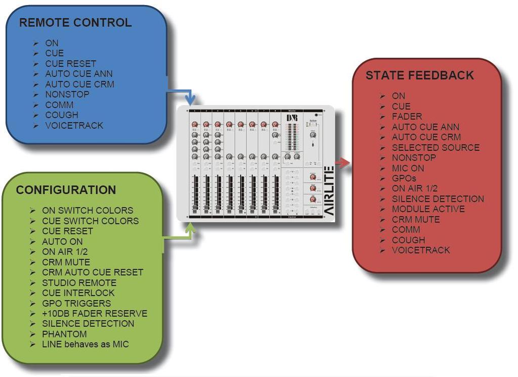
32 12 SOFTWARE OVERVIEW Below you see a blockdiagram of the many software possibilities and USB control streams that are running inside the AIRLITE console. See it as background info, because it is all happening automatically during use of the console. The blue REMOTE CONTROL block shows all the functions that can be remotely controlled. The green CONFIGURATION block shows all the functions you can program yourselve. The red STATE FEEDBACK block shows all the function changes that are sent to various indicators such as switch leds and the On screen meter application. 32
33 33
34 13 AIRLITE CONFIGURATION MANAGER Configuration Manager User Manual VERSION D&R Electronica B.V., Rijnkade 15B, 1382GS Weesp, The Netherlands Phone: +31 (0) , Fax: +31 (0) , Website:
35 13.1 Introduction Airlite Configuration Manager is a software tool to configure the Airlite console. This manual describes the features Airlite Configuration Manager contains and how to setup and use the application Connection & Setup Airlite Configuration Manager communicates indirectly with the Airlite console over an Ethernet connection using UDP/IP (User Datagram Protocol). Since the only available physical communication interface on the Airlite console is USB, another Airlite Control application is required to run on the PC the Airlite is connected to (main PC).The Airlite Control act as a USB/UDP gateway and provides a communication interface for client applications anywhere on the network, like Airlite Configuration Manager. In order to use Airlite Configuration Manager follow the steps below: 1. Connect the USB-main port of the Airlite to your PC with supplied USB cable 2. Install, configure and run the Airlite Control application on this main PC 3. Run Airlite Configuration Manager on any PC in the network, or from your home! 35
36 13.3 Communication Pressing Options->Communication from the menu bar will open the communication settings window Remote Host In the Remote Host field the IP address of the main PC needs to be specified. For running the Airlite Configuration Manager on the main PC one can use the (localhost) IP address Ports Airlite Configuration Manager uses a transmit- and receive port for the communication to/from the Airlite console. By default these ports are pre-configured and do not need to be changed unless specific port configuration is required. 36


37 13.4 Module Settings In this chapter the module settings for the eight modules present in the console are discussed. Each module has its own settings tab. Apply a configuration section of the selected module to all other modules. Apply entire configuration of the selected module to all other modules Power ON Active The Airlite console contains ON-switches to activate a specific module. If ON Active in the Power section is enabled the module will be active when powering the console. Using this function while a power outage occurs prevents silence on air if no person is in the studio to (re-)activate the module. 37
38 Auto CUE Reset When the CUE-switch of a module on the console is activated (also called PFL) the selected source (LINE or MIC/USB/VoIP) will be routed to the CUE buss. To deactivate a module from the CUE buss one can press again the CUE-switch. The Auto CUE Reset feature can reset the CUE buss (deactivate all modules from the CUE buss) automatically by Fader, ON and/or Fader+ON. The function can be enabled for LINE and MIC/USB/VoIP separately Fader Dynamics The fader top level can be set to +10dB instead of the normal 0dB level with this setting enabled. This results in 10dB more headroom which could be desirable in certain circumstances On Air Busses Two logical on-air busses are available which can be enabled for LINE and/or MIC/USB/VoIP for each module Switch Colors In the Switch Colors section the colors of the ON- and CUE switches can be configured to be OFF, RED, or GREEN depending on the state of the switch-function. It is up to the user to define a suitable color for a corresponding state. ON states: ON Active ON and Fader Active ON Inactive CUE states: CUE Active CUE Inactive CRM Feedback Prevention ** These settings are only available for modules 1,2 and 3 (MIC modules) ** In order to prevent feedback from a microphone in the Control Room the functions CRM Mute and CRM Auto Cue (AutoDeactivate) can be enabled. CRM Mute: Mute CRM buss when the module is active (MIC selected). CRM Auto Cue (AutoDeactivate) Deactivate the Auto Cue CRM function when cue ing module (MIC selected). 38
39 Studio Remote ** These settings are only available for modules 1,2 and 3 (MIC modules) ** With a studio remote connected to the GPI connector at the back of the console one is able to perform Cough and Comm (Communicate) functionality. Cough: if enabled the module is muted when the cough button on the studio remote is pressed Comm: if enabled the module is deactivated and put on the CUE buss when the comm button on the studio remote is pressed. Comm Private: if enabled the module is deactivated and put IF ONLY on the CUE buss when the comm button on the studio remote is pressed. (Comm must be enabled) Microphone ** These settings are only available for modules 1,2 and 3 (MIC modules) ** Phantom enables +48V power on the MIC XLR-connector required for condenser microphones. MIC at Line set this option if a microphone is connected at the line input (using external preamp). 39
 in the event of the signal going below the threshold (-40...0dB) after a given interval.")
40 13.5 Master Settings In this chapter the master settings of the console will be discussed Silence Detection The Airlite console is equipped with a software silence detection unit and is used to monitor the program buss (left, right or stereo) in the event of the signal going below the threshold ( dB) after a given interval. In this situation the unit will go into ALARM state and switches the nonstop source to the master output. The Interval Unit can be set to seconds or minutes. The red flashing nonstop switch on the console indicates the alarm state. The silence alarm can be reset by pressing the nonstop switch (will become green). Program buss is routed to the master output after the reset. 40
41 GPO The Airlite console contains two GPO s (General Purpose Output). These GPO s can be triggered by different events. In some cases the output needs to be inverted to obtain the correct result depending on the connected target (On- Air lamp e.g). The Inverted Output inverts the output of the GPO easily where otherwise a relay is needed. GPO Triggers: On Air 1 On Air 2 Phone Mic On Non Stop Module 1..8 Active The GPO s can be configured in continuous or pulse mode. Pulse mode can be used to trigger a cd-player when a module becomes active (faderstart). Pulse can be generated by ON, OFF, or ON/OFF state of the selected trigger. Pulse-width can be configured from milliseconds Switch Colors In the Switch Colors section the colors of the CUE switches for the Aux, Air, and NonStop can be configured to be OFF, RED, or GREEN depending on the state of the switch-function. It is up to the user to define a suitable color for a corresponding state. CUE states: CUE Active CUE Inactive Cue Buss Interlock If enabled only one module can be active on the CUE buss. Selecting a second module on the CUE buss will result in switching to this module. Pre listen to several modules can be done in a fast way with this feature. 41


42 13.6 Read/Write Configuration from/to console To read the configuration from the console into the Airlite Configuration Manager one needs to press the READ button. The Firmware field shows the current firmware in the console after the read command. Once the configuration is read successfully, adjustments can be made and written back to the console or saved as a preset. Pressing the WRITE button uploads the current configuration in Airlite Configuration Manager to the console. The configuration is directly active but not saved internally. The configuration is lost after a power off Store Internal The Store Internal button stores the current configuration in the console to persistent memory (EEPROM). This means the configuration is still active after a power off. A warning will be prompted to make sure you want to overwrite internal saved configuration Configuration Presets Airlite Configuration Manager is able to import/export the configuration from/to a preset file. These preset files have the.xml file extension. A preset file includes the module and master settings Create Preset Saving a preset can be done by pressing File->Save(as) from the menu bar Load Preset Loading a preset can be done by pressing File->Open from the menu bar and selecting the preset file. 42


294-416987, Website: http://www.")
43 14 AIRLITE METERS Meters User Manual VERSION D&R Electronica B.V., Rijnkade 15B, 1382GS Weesp, The Netherlands Phone: +31 (0) , Fax: +31 (0) , Website:

44 14.1 Introduction Airlite Meters is a software tool to let you as user monitor and control the Airlite console in an intuitive and user friendly manner. This manual describes the features Airlite Meters contains and how to setup and use the application Software elements Analog and Digital clock Airlite meters provides an analog as well as a digital clock which display PC system time the application is running on. The analog clock contains a seconds dot counter which can be used as indicator for program end time countdown PPM meters Two stereo PPM(Peak-Program-Meters) meters provide real-time and accurate readings of the Master- and CRM(Control Room Monitor) buss audio levels. A variety of PPM meter scales exist these days with all different range and read out. Based on the most used scale the following type is used: IEC Type I, DIN scale. This scale ranges from -50 till +5dB Silence detection Since continuous radio is important for a radio station, the Airlite is equipped with a built-in software silence detector which guards presence of audio signal on the master output. If no sound is present for a specified time, the console generates an alarm and switches automatically to non-stop mode. When the silence detector is active red line marks in the master PPM bars indicate the threshold as well as the operating mode which can be left, right or stereo MIC ON Timer The first three modules of the Airlite can be used for connecting microphones. If one of these mic modules is active (source selector is set to mic, ON is active and fader is up) the MIC ON timer will start. Once the timer is active the elapsed time is shown in the analog clock area below the system date. The timer will reset if all the mic modules are inactive. 44
45 Settings Pressing the gear wheel symbol at the right upper corner will open the (communication) settings window. Airlite Meters communicates indirectly with the console via a UDP/IP (User Datagram Protocol) connection. Since the only available communication interface on the Airlite console is USB, another Airlite Control application is required to run on the PC the Airlite is connected to. The Airlite Control act as a USB/UDP gateway and provides a communication interface for client applications anywhere on the network, like Airlite Meters Online indicator Below the D&R logo the online indicator is located. This indicator will become green (online) when receiving metering data. Make sure the Airlite Control application is running on the main PC in order to provide the metering data to Airlite Meters. When the indicator shows offline status (grey) the Airlite Control application is not running or the Airlite console is disconnected. 45
46 Console signals At the right side Airlite Meters contains a set of console signals indicating internal states of the console. PHONE: ON AIR 1/2: NONSTOP: SILENCE: MIC ON: CRM MUTE: Will inform you with an incoming call on module 8 (VoIP). Configurable Logical busses. Can be attached to a GPO for example. can be used as indicator as well as remote nonstop switch by clicking on the signal. Indicates the silence detector is in alarm state. In this alarm state NONSTOP is flashing to indicate the console has switched automatically to nonstop mode. The alarm can be reset by clicking on NONSTOP or by pressing the nonstop switch on the console. One of the mic modules is active. Behaves parallel to the hardware MIC ON output. CRM buss is muted by active mic module where crm-mute option is enabled Module states The Airlite console contains eight modules in which their current state is represented by the rectangular icons at the bottom of the application. Each icon show the state of the ON switch and the selected source of the relevant module ON-switch A module can be in one of the following three states: ACTIVE: ACTIVE_AND_FADER_ON: INACTIVE: ON active, fader down ON active, fader up ON inactive, fader down Since the ON switches of the Airlite console have internal LEDs, each of the above states can be configured to represent one of the following colors: NONE, RED, GREEN. It is up to the user to determine which color represent a particular state. The icons in Airlite Meters can be seen as duplicate of the ON switches and therefore behave as remote of the hardware switches. Clicking on the icons results in toggling the ON state. *** NOTE: If the icon flashes, the module is in voicetrack-mode Source select Each module can select between LINE and MIC/USB/VoIP source depending on the module. Additional to showing the ON switch state, the current selected source for each module will be shown in the right down corner of the icons. 46

47 14.3 Setup In order to use Airlite Meters follow the steps below: 4. Connect the USB-main port of the Airlite to your PC with supplied USB cable 5. Install, configure and run the Airlite Control application on this main PC 6. Run Airlite Meters on any PC in the network, or from your home! 47
48 15 UNDERSTANDING INTERNET RADIO One of the key features of the AIRLITE is you can set up your own Internet radio station from your home or office and have your friends listen to your broadcasts, be it music, talkshows, political, or religious programming. For more information on the Internet, follow the web links below. NOTE: D&R does not accept responsibility for the content of the following links or sites. How it works: Winamp: Shoutcast server: Shoutcast dsp plugin: The following paragraphs concerning the Internet might give you a better understanding about Internet radio. If you wish to set up a broadcast and you are a do-it-yourself kind of person - you might do well creating your own online radio station by using your own personal computer to create a dedicated server for doing the job. Some of the software options for getting this done include: SHOUTcast: SHOUTcast is one of the original free Internet radio software solutions for streaming audio. You can start your own station fairly easily and the software is free to download. =p ip_&tt=2&bt=1&bts=1&zu=http%3a// Helix Server Basic Free streaming media server software which can distribute live and on-demand video and other media. Realnetworks.com describes it as: Simple 5-stream server. This free media server is a great solution if you are getting started with streaming media and want to experiment before rolling it out to a large audience. The Helix Server Basic is free to download. Quicktime Streaming Server Apple.com says: Whether you are looking to add streaming media to your web site, deliver distance learning or provide rich content for your mobile subscribers, Mac OS X Server has all of the tools you need. QuickTime Streaming Server lets you deliver live or prerecorded content in real time over the Internet. You can find out more at apple.com. Quicktime Broadcaster Apple.com writes: Combining the power of QuickTime with Apple s ease of use, QuickTime Broadcaster allows just about any-one to produce a live broadcast event. Download this software from apple.com Peercast Peercast.org is a non-profit website that provides free peer-to-peer broadcasting software. PeerCast is a simple, free way to listen to radio and watch video on the Internet. It uses P2P technology to let anyone become a broadcaster without the costs of traditional streaming, according to the peercast.org website. Icecast Icecast is free server software for streaming multimedia. Download a copy from icecast.org. Andromeda Andromeda is delivery-on-demand software. Andromeda scans your MP3s and presents them as a fully-featured streaming Web site. That means you simply add, move, rename, and delete files and folders to update the contents of your Andromeda-powered site. It s as easy as drag, drop, stream, according to turnstyle.com where you can download an evaluation copy. 48
49 16 TECHNICAL SPECIFICATIONS 16.1 SPECIFICATIONS INPUTS. : Mic inputs : XLR connector balanced impedance 2 kohm. : Pin 1 = ground. : Pin 2 = hot (in phase). : Pin 3 = cold (out of phase). : +48 volt Phantom power : bal, 2 kohm, XLR.,48 volt Phantom. : Noise 128 dbr (A-weighted). (That 1501) : Sensitivity- 70dB min, OdB Max. LINE Phono inputs INSERTS. EQUALIZER Aux Return AIR in Aux returns USB USB CONTROL SECTION. START REMOTE OUTPUTS OPTIONAL OVERALL SOFTWARE : unbal, 10kOhm, Cinch. : Gain range of 40dB. : unbal. 47kOhm, 5 mv. (optional) : Stereo jack, -10dBv : Tip =Input (connect to output of signal processor) : Ring =Output (connect to input of signal processor) : Ground =shield : High: + / -12 db at 12kHz shelving. : Mid: + / -12dB at 1 khz bell curve. : Low: + / -12dB at 60 Hz shelving. : unbalanced 10kOhm -10dBv. : - 10 dbv at 10kOhm. : - 10 dbv at 10kOhm stereo : 4x Stereo in and 4x stereo out. : Fully compliant with USB 2.0 playback and record mode. 4x Stereo in and Main stereo or SUB signals out. HID Functions: Volume Mute Control : 16 free assignable illuminated switches, based on the HID protocol. : Stereo jack, Tip is a change over contact between sleeve and ring. NOT FOR 110/220 VOLT SWITCHING!!!!!!! It can only switch 24V/50mA max! : Left/Right + 6dBu bal. XLR. : Monitor/Aux + 6dBu unbal. on Cinch. : Headphone Ohm, Jack. : Announcer Ohm, Jack. : USB out Main program stereo signal or SUB : AES/EBU digital output card : Frequency response: Hz. : Distortion: < 0.01% max at 1 khz. : Start switch: isolated optical switch. (24volt/50mA) : Ledbars: 16 segment and on screen : A software protocol is available for programming of the USB HID protocol to match your software. 49
50 50
294-418 014 Fax : 0031 (0)294-416 987 Website : http://www.")
51 16.2 DIMENSIONS Left-Right Front-Back Height Front panel thickness Radius Corners Weight Drop through hole : 482 mm : 365 mm (8HE). : 103 mm. : 2 mm : 20 mm : 10 kg. : 449 x 344 mm We wish you many creative years of productivity using this quality product from: Company : D&R Electronica b.v. Address : Rijnkade 15B Zip Code : 1382 GS City : WEESP Country : The Netherlands Phone : 0031 (0) Fax : 0031 (0) Website : mail@d-r.nl 16.3 SUMMARY We hope this manual has given you sufficient information to use this new AIRLITE mixer in your studio. If you require more info please contact your local dealer or send us an at mail@d-r.nl and we will answer your within 24 hours during weekdays. In case you have bought this mixer from a previous owner, check out the dealer in your area on our website in case you need assistance. 51
MANUAL. v1.02. D&R Electronica B.V., Rijnkade 15B, 1382GS Weesp, The Netherlands
 MANUAL v1.02 D&R Electronica B.V., Rijnkade 15B, 1382GS Weesp, The Netherlands Phone: +31 (0)294-418014, Fax: +31 (0)294-416987, Website: http://www.d-r.nl, E-Mail: mail@d-r.nl W E B S T A T I O N M a
Radio for Everyone...
 Radio for Everyone... P R O D U C T I O N O N A I R C O N S O L E Eight dual inputs Built in auto Silence detector 4 USB in/out stereo channels Play out USB control section included AES 3 digital program
AIRMATE-USB MANUAL V 2.07
 AIRMATE-USB MANUAL V 2.07 Dear Client, Thank you for choosing the D&R AIRMATE-USB mixer. The AIRMATE-USB was designed by Radio Broadcast professionals along with the D&R design team and is intended to
TELEPHONE HYBRID-2 USER MANUAL. hybrid-2 manual page 1. Version 1.04 (smd)
") TELEPHONE HYBRID-2 USER MANUAL Version 1.04 (smd) hybrid-2 manual page 1 Dear Customer, Thank you for choosing the Telephone Hybrid-2. This time you are not faced with a huge manual because it is simply
TELEPHONE HYBRID-2 USER MANUAL Version 1.04 (smd) hybrid-2 manual page 1 Dear Customer, Thank you for choosing the Telephone Hybrid-2. This time you are not faced with a huge manual because it is simply
AIRLAB DT. User Manual. Version Airlab-DT manual Page 1
 AIRLAB DT User Manual Version 1.07 D&R ELECTRONICA BV Rijnkade 15B 1382 GS Weesp The Netherlands Phone: +31 (294) 418014 Fax: +31 (294) 416987 Website: http://www.d-r.nl E-mail: info@d-r.nl Airlab-DT manual
AIRLAB. User Manual. Mixing consoles Version 2.03
 AIRLAB User Manual Mixing consoles Version 2.03 D&R ELECTRONICA WEESP BV Rijnkade 15B 1382 GS Weesp The Netherlands Phone: +31 (294) 418014 Fax: +31 (294) 416987 Website: http://www.d-r.nl E-mail: info@d-r.nl
S0 Radio Broadcasting Mixer. June catalogue. Manufacturers of audio & video products for radio & TV broadcasters
 S0 Radio Broadcasting Mixer June 2012 catalogue Manufacturers of audio & video products for radio & TV broadcasters S0 Radio Broadcasting Mixer A simple radio mixer for novice and professional users The
ANALOG RADIO MIXER. Flexible. Affordable. Built To Last.
 ANALOG RADIO MIXER Flexible. Affordable. Built To Last. Audioarts AIR-4 A N A L O G R A D I O M I X E R At Audioarts, value engineering is straightforward: Define the features our customers require. Design
S1 Digital/Analogue Radio Broadcast Mixer September 2009
 S1 Digital/Analogue Radio Broadcast Mixer September 2009 www.sonifex.co.uk t: +44 (0)1933 650 700 f: +44 (0)1933 650 726 sales@sonifex.co.uk S1 Radio Digital/Analogue Broadcast Mixer Radio Broadcast Mixer
S1 Digital/Analogue Radio Broadcast Mixer
 S1 Digital/Analogue Radio Broadcast Mixer September 2009 www.sonifex.co.uk t: +44 (0)1933 650 700 f: +44 (0)1933 650 726 sales@sonifex.co.uk S1 Radio Digital/Analogue Broadcast Mixer Radio Broadcast Mixer
AIRLAB. User Manual. Mixing consoles Version 2.0
 AIRLAB User Manual Mixing consoles Version 2.0 D&R ELECTRONICA WEESP BV Rijnkade 15B 1382 GS Weesp The Netherlands Phone: +31 (294) 418014 Fax: +31 (294) 416987 Website: http://www.d-r.nl E-mail: info@d-r.nl
AxumVideo 0 intro. Now that you have connected the different AXUM system parts, you are ready to configure the system according to your own needs.
 AxumVideo 0 intro Now that you have connected the different AXUM system parts, you are ready to configure the system according to your own needs. On the left we see the RACK unit and on the right we see
FF DUAL FORMAT DJ MIXER USERS MANUAL
 FF - 4000 DUAL FORMAT DJ MIXER USERS MANUAL FF - 4000 INTRODUCTION The features and layout of the FF-4000 were determined in collaboration with leading loudspeaker manufacturers Funktion One, who canvassed
Overview. A 16 channel frame is shown.
 Overview A 16 channel frame is shown. 22 Mono Input Channel 1 - MIC INPUT The mic input accepts XLR-type connectors and is designed to suit a wide range of BALANCED or UNBALANCED signals. Professional
T L Audio. User Manual C1 VALVE COMPRESSOR. Tony Larking Professional Sales Limited, Letchworth, England.
 T L Audio User Manual C1 VALVE COMPRESSOR Tony Larking Professional Sales Limited, Letchworth, England. Tel: 01462 490600. International +44 1462 490600. Fax: 01462 490700. International +44 1462 490700.
EN Dateq BCS25 Manual Safety instructions 3. 1 All safety instructions, warnings and operating instructions must be read first.
 BCS25 USER MANUAL EN Dateq BCS25 Manual Safety instructions 3 Safety instructions 1 All safety instructions, warnings and operating instructions must be read first. 2 All warnings on the equipment must
PHOENIX AUDIO. Owner s Manual
 PHOENIX AUDIO Costa Mesa CA 92262 USA Telephone +1 866 302 1091 Email :sales@phoenixaudio.net Owner s Manual Firstly, let us congratulate you on your purchase of the Ascent-Two Microphone Pre- Amplifier.
CHAPTER 3 AUDIO MIXER DIGITAL AUDIO PRODUCTION [IP3038PA]
![CHAPTER 3 AUDIO MIXER DIGITAL AUDIO PRODUCTION [IP3038PA]](/thumbs/73/68858919.jpg "CHAPTER 3 AUDIO MIXER DIGITAL AUDIO PRODUCTION [IP3038PA]") CHAPTER 3 AUDIO MIXER DIGITAL AUDIO PRODUCTION [IP3038PA] Learning Objectives By the end of this chapter, students should be able to: 1 State the function of the audio mixer in the sound studio. 2 Explain
CHAPTER 3 AUDIO MIXER DIGITAL AUDIO PRODUCTION [IP3038PA] Learning Objectives By the end of this chapter, students should be able to: 1 State the function of the audio mixer in the sound studio. 2 Explain
TL AUDIO M4 TUBE CONSOLE
 TL AUDIO M4 TUBE CONSOLE USER MANUAL TL AUDIO M4 TUBE CONSOLE M4 INTRODUCTION... 3 M4 MIXER TECHNICAL SPECIFICATION... 4 Mic Input:... 4 Line Input:... 4 Phase Rev:... 4 High Pass Filter:... 4 Frequency
MIDAS Venice Pin-Assignments Page 1 / 3 Mono-Channel-PCB Stereo- / Master - PCB CN 1 circuit diagram number CN 6 circuit diagram number CN
 MIDAS Venice Pin-Assignments Page 1 / 3 Mono-Channel-PCB 81346 Stereo- / Master - PCB 82230 CN 1 circuit diagram number CN 6 circuit diagram number CN 7 circuit diagram number CN 1 circuit diagram number
PHASE HL SEL 1 HL SEL 2 EXT MONITOR ELAN ELAN ELAN ELAN MLM-201 HLM-201 HLM-201 TBM-201 MLM-201 GAIN GAIN GAIN LEFT GAIN RIGHT SELECT SELECT SELECT
 Audio Promotional Information "Kestrel-12" and "Kestrel-16" Modular Dual Channel Stereo "On-Air" Mixer "Kestrel-12" "KESTREL-12" HL SEL 1 HL SEL 2 EXT MITOR VU O'LOAD PHASE VU VU AUDIO AIR DELAY DUMP TLM-201
Solid State Logic S O U N D V I S I O N
 Solid State Logic S O U N D V I S I O N SUPERANALOGUE X - R A C K Super-Analogue Outboard XR622 X-Rack Master Module User s Guide This documentation package contains the User s Guide for your new X-Rack
AIR 2 + RADIO CONSOLE
 AIR 2 + RADIO CONSOLE TECHNICAL MANUAL November 2006 AIR 2+ Radio Console Technical Manual - 1st Edition 2006 Audioarts Engineering* AUDIOARTS ENGINEERING 600 Industrial Drive New Bern, North Carolina
XB-14 Quick Operation Manual V1 23/10/2013
 XB-14 Quick Operation Manual V1 23/10/2013 14. MIXER ON/OFF SWITCH 19. USB GAIN CONTROL 17. ST1 18. ST16 SELECTOR SELECTOR 7. GAIN CONTROL 6. 100Hz HIGH PASS FILTER 13. MAIN 16. GAIN 5. EQ METERS 12. PHANTOM
innkeeper LTD Digital Hybrid User Guide JK Audio
 innkeeper LTD Digital Hybrid User Guide JK Audio Introduction Innkeeper LTD allows you to send line level signals into the phone line while maintaining excellent separation between your voice and the caller.
AEQ BRAVO Broadcast Mixing Console
 AEQ Broadcast Mixing Console USER S MANUAL ED. 12/07 V. 1.5-20/05/2008 CONTENTS 1. INTRODUCTION... 3 1.1. General... 3 1.2. Maintenance... 3 1.3. Warranty... 4 2. EQUIPMENT POWER SUPPLY... 5 2.1. General...
BSM Evolution USB - Compact ON AIR console. BSM Evolution USB. AEV On Air compact broadcast console
 BSM Evolution USB AEV On Air compact broadcast console 1 Guarantee The equipment is warranted for a period of 2 years from the date of invoice (ex-works). The warranty does not cover faults provoked by
Natural-sounding telephone audio... Hybrids
 Natural-sounding telephone audio... Hybrids ... for broadcast, conferencing and public address About Comrex DH Series Digital Telephone Hybrids When you want to present, broadcast, or record a telephone
3124mb+ All Discrete 4 Channel Mic/Instrument Preamplifier with Stereo Mixer Operator s Manual
 3124mb+ All Discrete 4 Channel Mic/Instrument Preamplifier with Stereo Mixer Operator s Manual Written by Carl J Houde 2015 Table of Contents 1.0 Introduction... 3 2.0 Overview... 4 2.1 3124mb+ Features
AEQ BRAVO Broadcast Mixing Console
 AEQ Broadcast Mixing Console USER S MANUAL ED 12/07 V 11-17/12/2007 CONTENTS 1 INTRODUCTION 3 11 General 3 12 Maintenance 3 13 Warranty 4 2 EQUIPMENT POWER SUPPLY 5 21 General 5 22 Switching on the equipment
DM1624, DM1612, DM812
 Installation Guide Hardware and Software DM Series Digital Processors models DM1624, DM1612, DM812 LECTROSONICS, INC. 1 Installation Specific Information Only This guide covers only installation related
SERIES 10 USER GUIDE
 SERIES 10 USER GUIDE Soundcraft Electronics Ltd. 1992, 1993 All rights reserved Parts of the design of this product may be protected by worldwide patents. Issue 2 Part No. ZM0004 Information in this manual
GS-CU001M COMMENTATOR UNIT PRODUCT DETAILS
 GLENSOUND ELECTRONICS LTD GS-CU001M COMMENTATOR UNIT PRODUCT DETAILS 6 BROOKS PLACE, MAIDSTONE, KENT, ME1 1HE. ENGLAND. TEL: + (0) 1622 7020 Visit our Website at www.glensound.co.uk + (0) 1622 7662 FAX:
Time For Change GS-HL-005. Single Unit Commentary. Key Points. Single Unit Commentary. Glensound. COIN GT-013 Glensound Commentary Telex Intercom
 Single Unit Commentary Time For Change commentary & intercom Single user commentary system High specification mic input with compressor 48v Phantom Power GS-HL-005 Three source Headphone Monitoring - Talk
LPFM LOW POWER FM EQUIPMENT GUIDE
 LPFM LOW POWER FM EQUIPMENT GUIDE BROADCAST AUDIO PERFECTIONISTS LPFM low power FM equipment guide One of the challenges in launching a new LPFM station is assembling a package of equipment that provides
MX-206 Stereo Microphone Mixer. Operating Manual
 MX-206 Stereo Microphone Mixer Operating Manual ASHLY AUDIO INC. 847 Holt Road Webster, NY 14580-9103 Phone: (585) 872-0010 Toll-Free: (800) 828-6308 Fax: (585) 872-0739 www.ashly.com Operating Manual
Vortex / VSX TM 8000 Integration
 Vortex / VSX TM 8000 Integration Application Note Polycom Installed Voice Business Group December 2004 1 TABLE OF CONTENTS INTRODUCTION...4 CONNECTING THE VSX 8000 INPUTS AND OUTPUTS...4 ENABLING THE VSX
CXM Mixer Installation & User Guide
 CXM Mixer Installation & User Guide Cloud Electronics Limited 140 Staniforth Road, Sheffield, S9 3HF England Tel +44 (0)114 244 7051 Fax +44 (0)114 242 5462 e-mail info@cloud.co.uk web site http://www.cloud.co.uk
Oxygen ORDERCODE D2150
 Oxygen ORDERCODE D2150 Congratulations! You have bought a great, innovative product from DAP Audio. The DAP Audio Oxygen brings excitement to any venue. Whether you want simple plug-&-play action or a
12 Channel Media Splitter MS12 Mk2 User manual
 12 Channel Media Splitter MS12 Mk2 User manual 01. 12 Channel Media Splitter MS12 Mk2 An audio distribution amplifier primarily designed to feed multiple ENG cameras from a single lectern microphone at
MANUAL ENGLISH Core Club Ordercode: D2314
 MANUAL ENGLISH Core Club Ordercode: Highlite International B.V. Vestastraat 2 6468 EX Kerkrade the Netherlands Table of contents Warning... 2 Unpacking Instructions... 2 Safety Instructions... 2 Operating
CMX-DSP Compact Mixers
 CMX-DSP Compact Mixers CMX4-DSP, CMX8-DSP, CMX12-DSP Introduction Thank you for choosing a Pulse CMX-DSP series mixer. This product has been designed to offer reliable, high quality mixing for stage and/or
Recording to Tape (Analogue or Digital)...10
...10") c o n t e n t s DUAL MIC-PRE Green Dual Mic Pre (introduction).............................4 Section (i): Setting Up Power Connections...........................................4 Power Supply................................................5
c o n t e n t s DUAL MIC-PRE Green Dual Mic Pre (introduction).............................4 Section (i): Setting Up Power Connections...........................................4 Power Supply................................................5
Output Board - v2* 4.1 Overview. 4.2 Audio Circuitry Program and Audition Outputs
 Output Board - v2* 4.1 Overview This circuit board provides the following console functions: Line output amplification Cue amplification Headphone amplification External Inputs (balanced *) Monitor sends
USER GUIDE MULTI-CHANNEL STEREO MIXER S MIX 4M2S UD
 USER GUIDE MULTI-CHANNEL STEREO MIXER S MIX 4M2S UD FEATURES 4 mono input channels and 2 stereo input channels. Frequency EQ on each input channel. Low-noise mic pre-amp on microphone inputs. Low cut filter
CLOCKAUDIO. MR88 Automatic Microphone Mixer. Version 4.2
 CLOCKAUDIO MR88 Automatic Microphone Mixer Version 4.2 Clockaudio Limited,22 Arnside Road WATERLOOVILLE Hampshire. UK Tel : +44 (0)2392 251193 Fax : +44 (0)2392 251201 Email : sales@clockaudio.co.uk CONTENTS
CDM10: Channel USB Mixer. Item ref: UK User Manual
 CDM10:4 19 4 Channel USB Mixer Item ref: 171.135UK User Manual Caution: Please read this manual carefully before operating Damage caused by misuse is not covered by the warranty Introduction Thank you
MCM-20.4 PRELIMINARY USER GUIDE v1.1
 MCM-20.4 PRELIMINARY USER GUIDE v1.1 2017 All the documentation included in this manual is copyrighted by Heritage Audio S.L. All rights are reserved. No part of this manual may be reproduced, copied,
CFX 12 (12X4X1) 8 mic/line channels, 2 stereo line channels. CFX 16 (16X4X1) 12 mic/line channels, 2 stereo line channels
 8 mic/line channels, 2 stereo line channels. CFX 16 (16X4X1) 12 mic/line channels, 2 stereo line channels") COMPACT CFX MIXERS COMPACT SOUND REINFORCEMENT MIXERS WITH EFX FOR THE GIGGING MUSICIAN THREE MODELS CFX 12 (12X4X1) 8 mic/line channels, 2 stereo line channels CFX 16 (16X4X1) 12 mic/line channels, 2
COMPACT CFX MIXERS COMPACT SOUND REINFORCEMENT MIXERS WITH EFX FOR THE GIGGING MUSICIAN THREE MODELS CFX 12 (12X4X1) 8 mic/line channels, 2 stereo line channels CFX 16 (16X4X1) 12 mic/line channels, 2
AM-4 Audio Monitor. Videoquip Research Limited 595 Middlefield Road, Unit #4 Scarborough, Ontario, Canada. MIV 3S2
 AM-4 Audio Monitor Videoquip Research Limited 595 Middlefield Road, Unit #4 Scarborough, Ontario, Canada. MIV 3S2 (416) 293-1042 1-888-293-1071 www.videoquip.com AM-4 4 channel Analog, AES3 Digital, SDI
MX 3BT NF TK MAIN 2TK 2TK BT
 MX.3BT MX 3BT BT MAIN NF03852-1.1 The mains plug or an appliance coupler is used as the disconnect device, the disconnect device shall remain readily operable. 1. INTRODUCTION...4 2. FEATURES...4 3. INSTRUCTION...4
STUDIO Q User Guide. Radial Engineering Ltd Kebet Way, Port Coquitlam BC V3C 5M5 Tel: Fax:
 TM STUDIO Q User Guide 1588 Kebet Way, Port Coquitlam BC V3C 5M5 Tel: 604-942-1001 Fax: 604-942-1010 Email: info@radialeng.com Studio-Q Talk Back Interface Overview... 1 Features...2-3 Making Connections...4-5
SYNERGY MINI DIGITAL BROADCAST CENTRE
 SYNERGY MINI DIGITAL BROADCAST CENTRE SYNERGY MINI is more than just a radio mixer. Much more. SYNERGY MINI is a multifunction digital broadcast centre allowing you to record, produce and broadcast both
SOUNDCRAFT USER GUIDE
 SOUNDCRAFT USER GUIDE Soundcraft Electronics 1995 All rights reserved Parts of the design of this product may be protected by worldwide patents. Part No. ZM0078-03 Information in this manual is subject
PROFESSIONAL 2 CHANNEL SOLID-STATE MIC / LINE PREAMPLIFIER USER S MANUAL
 PROFESSIONAL 2 CHANNEL SOLID-STATE MIC / LINE PREAMPLIFIER USER S MANUAL SAFETY INSTRUCTIONS This symbol, wherever it appears, alerts you to important operating and maintenance instructions in the accompanying
S MiX 2M2S UF. S MiX 2M2S F
 USER guide MULTI-CHANNEL STEREO MIXER S MiX 2M2S UF S MiX 2M2S F FEATURES 2 stereo input channels and 2 mono input channels. 2-band frequency EQ for each input channel. Low-noise mic pre-amp on microphone
clipping; yellow LED lights when limiting action occurs. Input Section Features
 ELX-1A Rack-Mount Mic/Line Mixer Four inputs, one output in a single rack space Very-highery-high-quality audio performance High reliability Extensive filtering circuitry and shielding protect against
DP1 DYNAMIC PROCESSOR MODULE OPERATING INSTRUCTIONS
 DP1 DYNAMIC PROCESSOR MODULE OPERATING INSTRUCTIONS and trouble-shooting guide LECTROSONICS, INC. Rio Rancho, NM INTRODUCTION The DP1 Dynamic Processor Module provides complete dynamic control of signals
Model 50 Central Controller, Model 51 Control Console, and Related Components. User Guide
 Model 50 Central Controller, Model 51 Control Console, and Related Components User Guide Issue 5, June 2002 This User Guide is applicable for systems consisting of: Model 50, serial number M50-00385 to
spider a bit of information
 spider a bit of information Please read this before connecting power to the unit. There are important things about the power cable and cooling that must be done to allow for long life and reliable operation.
USER MANUAL MX102 & MX1202
 USER MANUAL MX102 & MX1202 WWW.PULSE-AUDIO.CO.UK 1 SAVE THESE SAFETY INSTRUCTIONS Thank you for purchasing our product. To assure the optimum performance, please read this manual carefully and keep it
Summit Audio Model TLA-50 Tube Leveling Amplifier
 Summit Audio Model TLA-50 Tube Leveling Amplifier ATTACK FAST SLOW MEDIUM 3 4 5 6 7 TUBE LEVELER 40 60 80 100 VU 3 4 5 6 TLA-50 7 FAST SLOW RELEASE OUTPUT RED. METER 2 1 0 10 GAIN 9 8 7 5 3 1 0 1 2 +3
The Dangerous Music D-Box user s operating guide
 The Dangerous Music D-Box user s operating guide Thank you for choosing products from the exciting line of Dangerous Music recording equipment. Many years of dependable and trouble-free service can be
SAFETY PRECAUTIONS. The SPIRIT FX16 mixer must only be connected through the Power Supply supplied:
 INTRODUCTION Thank you for purchasing an FX16 mixer, brought to you with pride by the SPIRIT team of Andy, Colin, Chris, Simon, Mukesh, Graham, Martin, Paul, Tony and Peter, with the support of many others
PLAYMATE PROFESSIONAL STEREO 19 MIXER, USB/SD CARD AND BLUETOOTH PLAYER. User Guide and Reference Manual. page 1
 PLAYMATE PROFESSIONAL STEREO 19 MIXER, USB/SD CARD AND BLUETOOTH PLAYER User Guide and Reference Manual page 1 INTRODUCTION Congratulations and thank you for purchasing the NewHank Playmate mixer. This
Studio Notes. SQN-3 Mono Microphone Mixer
 Studio Notes SQN-3 Mono Microphone Mixer The SQN-3 Mixer The SQN-3 audio mixer is a 4 into 1 monophonic mixer. It is powered from 6 AA size alkaline batteries and these are located at the rear right of
MANUAL DE INICIO RÁPIDO ESPAÑOL ( 7 10 ) GUIDE D UTILISATION RAPIDE FRANÇAIS ( ) MANUALE RAPIDO DI UTILIZZAZIONE ITALIANO ( )
 GUIDE D UTILISATION RAPIDE FRANÇAIS ( ) MANUALE RAPIDO DI UTILIZZAZIONE ITALIANO ( )") QUICKSTART GUIDE ENGLISH ( 6 ) MANUAL DE INICIO RÁPIDO ESPAÑOL ( ) GUIDE D UTILISATION RAPIDE FRANÇAIS ( 4 ) MANUALE RAPIDO DI UTILIZZAZIONE ITALIANO ( 5 ) KURZANLEITUNG DEUTSCH ( 22 ) INTRODUCTION Welcome
QUICKSTART GUIDE ENGLISH ( 6 ) MANUAL DE INICIO RÁPIDO ESPAÑOL ( ) GUIDE D UTILISATION RAPIDE FRANÇAIS ( 4 ) MANUALE RAPIDO DI UTILIZZAZIONE ITALIANO ( 5 ) KURZANLEITUNG DEUTSCH ( 22 ) INTRODUCTION Welcome
SOUNDCRAFT. User Guide
 SOUNDCRAFT User Guide Harman International Industries Ltd. 1996,1997 All rights reserved Parts of the design of this product may be protected by worldwide patents. Part No. ZM0143 Issue 3 Soundcraft is
MCM-32 PRELIMINARY USER GUIDE v1.0
 MCM-32 PRELIMINARY USER GUIDE v1.0 2016 Heritage Audio S.L. is the solely owner of the copyright of all information and drawings contained in this manual which are not to be copied or reproduced by any
1608-II and 2448 Recording Console Operator s Manual
 Recording Console Operator s Manual Written for Automated Processes ncorporated by Dan Pfeifer Rev. 18-12-30 2018 8301 Patuxent Range Road Jessup, MD 20794 USA 301-776-7879 http://www.apiaudio.com Table
M A S T E R S E C T I O N. User Manual
 M A S T E R S E C T I O N User Manual Version 1.02: July 2007 Contents. Safety Information.... 3 Welcome.... 4 Connections.... 5 A Basic Set-up 5 Setting Up.... 7 Adjusting Input Levels 7 Taking Account
EELA AUDIO SRM USERS MANUAL
 USERS MANUAL This manual provides the aspirant user of an EELA AUDIO SRM RADIODESK with the information, needed for operating and maintaining the equipment. Chapters 1 and 4 have to be read by anyone,
ex 800 Series ematrix System
 Protecting Your Human Assets During Emergency ex 800 Series ematrix System The ex 800 Series ematrix System is a fully integrated and versatile public address system which is designed distinctively to
C8000. switch over & ducking
 features Automatic or manual Switch Over or Fail Over in case of input level loss. Ducking of a main stereo or surround sound signal by a line level microphone or by a pre recorded announcement / ad input.
Element 78 MPE-200. by Summit Audio. Guide To Operations. for software version 1.23
 Element 78 MPE-200 by Summit Audio Guide To Operations for software version 1.23 TABLE OF CONTENTS IMPORTANT SAFETY AND GROUNDING INSTRUCTIONS COVER 1. UNPACKING AND CONNECTING...3 AUDIO CONNECTIONS...4
CM4-BT. Compact Mixer with Bluetooth UK User Manual
 CM4-BT Compact Mixer with Bluetooth 170.804UK User Manual Caution: Please read this manual carefully before operating Damage caused by misuse is not covered by the warranty Introduction: Thank you for
Introduction SAFETY PRECAUTIONS. Contents
 0 0 0 0 9 8 7 6 0 0 9 8 7 6 0 0 9 8 7 6 0 Contents Introduction Safety Precautions Connections System Overview Controls in Detail Inputs Master 7 Advanced Features 8 Initial Setting Up 9 Applications 0
X D M PREAMP MIXER
 User Instructions X D M - 3 5 2 PREAMP MIXER Thank you for purchasing this American DJ product. The XDM-352 is ready to be used, there is no assembly required. Please read the following instructions before
CR-6 MIXER USER MANUAL ENGLISH. Order Code: MIXE01
 CR-6 MIXER P R O F E S S I O N A L 1 9 R A C K M I X E R Order Code: MIXE01 w w w. p r o l i g h t. c o. u k USER MANUAL ENGLISH WARNING FOR YOUR OWN SAFETY, PLEASE READ THIS USER MANUAL CAREFULLY BEFORE
SM12 & SM16 STEREO MIC/LINE MIXING CONSOLES OPERATION MANUAL
 SM12 & SM16 STEREO MIC/LINE MIXING CONSOLES OPERATION MANUAL INTRODUCTION AND CONTENTS The Australian Monitor Pro Series SM12 and SM16 stereo console mixers are designed to be compact, ultra low noise
X-Panda User s Guide
 X-Panda User s Guide This documentation is intended to be read along side the X-Panda Installation Guide which is available for download from our website www.solidstatelogic.com 82BXEM01A Contents Introduction
OWNERS MANUAL LUNATEC V3 MICROPHONE PREAMPLIFIER AND A/D CONVERTER
 OWNERS MANUAL LUNATEC V3 MICROPHONE PREAMPLIFIER AND A/D CONVERTER LUNATEC 35 +48 35 +48 30 40 30 40 0 25 45 25 45 3 192 1 1 6 176.4 20 50 20 50 9 96 12 PEAK 88.2 55 55 RESET 48 10 60 2 10 60 2 21 44.1
Introducing the New Daking Console
 Introducing the New Daking Console Daking The Console that can change from a Legacy Bussing scheme to DAW Direct Routing with the touch of a button. Features: Class A Circuitry Transformer Coupled Pre-Amps
Octagonman.lwp OCTAGON. (version1.2) OWNERS MANUAL. Octagon page number 1
 OWNERS MANUAL. Octagon page number 1") Octagonman.lwp OCTAGON (version1.2) OWNERS MANUAL Octagon page number 1 Octagon Manual Introduction and Product Overview 1.0 The Chassis system - description 1.1 Octagon chassis 2.0 Master section - description
Octagonman.lwp OCTAGON (version1.2) OWNERS MANUAL Octagon page number 1 Octagon Manual Introduction and Product Overview 1.0 The Chassis system - description 1.1 Octagon chassis 2.0 Master section - description
SRP-V200. Audio Mixer
 Audio Mixer SRPV00 The versatile Sony SRPV00. Six stereo inputs, four mono inputs, four mixing buses and a full range of operational features combined in a single, compact unit. Use the parallel control
MULTIMIX 8/4 DIGITAL AUDIO-PROCESSING
 MULTIMIX 8/4 DIGITAL AUDIO-PROCESSING Designed and Manufactured by ITEC Tontechnik und Industrieelektronik GesmbH 8200 Laßnitzthal 300 Austria / Europe MULTIMIX 8/4 DIGITAL Aim The most important aim of
AMU2-2MHD+ Audio monitoring Unit
 AMU2-2MHD+ Audio monitoring Unit Handbook TSL Vanwall Road, Maidenhead, Berkshire, SL6 4UB Telephone +44 (0)1628 676200, FAX +44 (0)1628 676299 AMU2-2MHD+-6 1 ISSUE 5 SAFETY Installation. Unless otherwise
LX20 OPERATORS MANUAL
 LX20 OPERATORS MANUAL CONTENTS SAFETY CONSIDERATIONS page 1 INSTALLATION page 2 INTRODUCTION page 2 FIRST TIME USER page 3 SYSTEM OPERATING LEVELS page 3 FRONT & REAR PANEL LAYOUT page 4 OPERATION page
SCM820 Digital IntelliMix Automatic Mixer SEAMLESS MIXING. ADVANCED CONTROL.
 SCM820 Digital IntelliMix Automatic Mixer SEAMLESS MIXING. ADVANCED CONTROL. SCM820 Digital IntelliMix Automatic Mixer The SCM820 is the flagship Shure digital automatic mixer for seamless, natural-sounding
Neve :2 Summing Mixer User Manual
 Neve 8816 16:2 Summing Mixer User Manual 527-361 Issue 5 AMS NEVE Billington Road Burnley Lancs BB11 5UB England Phone +44 (0)1282 457011 Fax: +44 (0)1282 417282 info@ams-neve.com www.ams-neve.com www.neve.eu
DMP3. Users Manuual. Ver. # DMP
 TM AUDIO DMP3 Users Manuual Ver. # DMP3-121701 Table of Contents Introduction.......................................................2 DMP3 Features....................................................2
X-Four console. description. features. sound fundamentals. built to defy murphy s law. wide range of configurations
 X-Four console description If your application requires all the features and performance of a thoroughly-professional mixing console, but presents severe spacerestrictions, then the Crest Audio X-Four
USER GUIDE TO THE ARENA OPERATION
 USER GUIDE TO THE ARENA OPERATION The mean of this guide is to help as a a quick reference guide to the operation of the most common functions of the ARENA console. It is not a substitute of the operation
PROFESSIONAL 2-CHANNEL MIXER WITH EFFECTS LOOP
 PROFESSIONAL 2-CHANNEL MIXER WITH EFFECTS LOOP QUICKSTART GUIDE ENGLISH ( 1 4 ) GUÍA DE INICIO RÁPIDO ESPAÑOL ( 5 8 ) GUIDE D UTILISATION SIMPLIFIÉ FRANÇAIS ( 9 12 ) GUIDA RAPIDA ITALIANO ( 13 16 ) KURZANLEITUNG
Mixers. The functions of a mixer are simple: 1) Process input signals with amplification and EQ, and 2) Combine those signals in a variety of ways.
 Process input signals with amplification and EQ, and 2) Combine those signals in a variety of ways.") Mixers The mixer is the central device in any sound studio. Although you can do a lot without it, sooner or later you are going to want to bring all of your materials together to make a piece of music,
Mixers The mixer is the central device in any sound studio. Although you can do a lot without it, sooner or later you are going to want to bring all of your materials together to make a piece of music,
y AW4416 Audio Workstation Signal Flow Tutorial
 y AW44 Audio Workstation Signal Flow Tutorial This tutorial will help you learn the various parts of a CHANNEL by following the signal through #1. Use the Signal Flow Diagram included with this document.
Table of Contents. Introduction 2 C valve Features 3. Controls and Functions 4-5 Front Panel Layout 4 Rear Panel Layout 5
 Safety Instructions Table of Contents Introduction 2 C valve Features 3 Controls and Functions 4-5 Front Panel Layout 4 Rear Panel Layout 5 Operating the C valve 6-13 Setting Up the C valve 6-7 Setting
DH400. Digital Phone Hybrid. The most advanced Digital Hybrid with DSP echo canceller and VQR technology.
 Digital Phone Hybrid DH400 The most advanced Digital Hybrid with DSP echo canceller and VQR technology. The culmination of 40 years of experience in manufacturing at Solidyne, broadcasting phone hybrids,
+41 * 2 db. GENERAL The Shure M675 Broadcast Production Master is designed for use in conjunction with a Shure M67 or
 2 2 2 HARTREY AVE., EVANSTON, IL. 6 0 2 0 4 U.S.A. GENERAL The Shure M675 Broadcast Production Master is designed for use in conjunction with a Shure M67 or M67-2E Professional Microphone Mixer, M63 Audio
Operations Manual. Last Updated: 11/10/2013. P Squared Ltd
 Operations Manual Last Updated: 11/10/2013 P Squared Ltd Limited Warranty Definitions the Company means P Squared Ltd and where relevant includes companies within the same group of companies as P Squared