CAUTION RISK OF ELECTRIC SHOCK DO NOT OPEN
|
|
|
- Lora Edwards
- 6 years ago
- Views:
Transcription
1
2 WARNING FOR YOUR PROTECTION, PLEASE READ THE FOLLOWING: WATER AND MOISTURE: Appliance should not be used near water (e.g. near a bathtub, washbowl, kitchen sink, laundry tub, in a wet basement, or near a swimming pool, etc). Care should be taken so that objects do not fall and liquids are not spilled into the enclosure through openings. POWER SOURCES: The appliance should be connected to a power supply only of the type described in the operating instructions or as marked on the appliance. GROUNDING OR POLARIZATION: Precautions should be taken so that the grounding or polarization means of an appliance is not defeated. POWER CORD PROTECTION: Power supply cords should be routed so that they are not likely to be walked on or pinched by items placed upon or against them, paying particular attention to cords at plugs, convenience receptacles, and the point where they exit from the appliance. SERVICING: To reduce the risk of fire or electric shock, the user should not attempt to service the appliance beyond that described in the operating instructions. All other servicing should be referred to qualified service personnel. FOR UNITS EQUIPPED WITH EXTERNALLY ACCESSIBLE FUSE RECEPTACLE: Replace fuse with same type and rating only. CAUTION RISK OF ELECTRIC SHOCK DO NOT OPEN ATTENTION: RISQUE DE CHOC ELECTRIQUE - NE PAS OUVRIR WARNING: TO REDUCE THE RISK OF FIRE OR ELECTRIC SHOCK DO NOT EXPOSE THIS EQUIPMENT TO RAIN OR MOISTURE The symbols shown above are internationally accepted symbols that warn of potential hazards with electrical products. The lightning flash with arrowpoint in an equilateral triangle means that there are dangerous voltages present within the unit. The exclamation point in an equilateral triangle indicates that it is necessary for the user to refer to the ownerõs manual. These symbols warn that there are no user serviceable parts inside the unit. Do not open the unit. Do not attempt to service the unit yourself. Refer all servicing to qualified personnel. Opening the chassis for any reason will void the manufacturerõs warranty. Do not get the unit wet. If liquid is spilled on the unit, shut it off immediately and take it to a dealer for service. Disconnect the unit during storms to prevent damage. ELECTROMAGNETIC COMPATIBILITY This unit conforms to the Product Specifications noted on the Declaration of Conformity. Operation is subject to the following two conditions: this device may not cause harmful interference, and this device must accept any interference received, including interference that may cause undesired operation. Operation of this unit within significant electromagnetic fields should be avoided. DECLARATION OF CONFORMITY ManufacturerÕs Name: ManufacturerÕs Address: declares that the product: Product Options: dbx Professional Products 8760 S. Sandy Parkway Sandy, Utah 84070, USA dbx MC6 Mini-Compª Requires a Class II power adapter that conforms to the requirements of EN60065, EN60742, or equivalent. conforms to the following product specifications: Safety: EN (1993) IEC 65 (1987) with Amendments 1, 2, 3 EMC: EN (1990) EN (1991) Supplementary Information: The product herewith complies with the requirements of the EMC Directive 89/336/EEC (1989), as amended by directive 93/68/EEC (1993). dbx Professional Products Vice President of Engineering 8760 S. Sandy Parkway Sandy, Utah 84070, USA August 1,1997 European Contact: Your Local dbx Sales and Service Office or International Sales Office 68 Sheila Lane Valparaiso, Indiana 46383, USA Tel: (219) Fax: (219)
3 MANUAL CONTENTS MC6 FRONT PANEL 2 MC6 REAR PANEL 6 CONNECTING THE MC6 TO YOUR SYSTEM 7 APPLICATIONS 8 FACTORY SERVICE / WARRANTY 10 SPECIFICATIONS 11 1
4 Congratulations on choosing the dbx MC6 Mini-Comp Compressor. The MC6 provides traditional dbx sonic quality and performance for the working musician, DJ, studio operator or anyone who needs a friendly compressor to achieve professional quality compression quickly and easily.we re sure you ll agree that the MC6 Mini-Comp is the most affordable professional quality stereo compressor on the market today. We recommend that you take a moment and read through the manual as it provides information that will assist you in using your unit to its fullest potential.to help you use the MC6 in any environment, we uncluded four rubber feet for table-top use, and an attachable spring steel clip for securing the MC6 to a guitar amp handle. The MC6 Mini-Comp Compressor is packed with just the right features to effectively reduce and control the dynamic range of your audio, add punch to flabby, loose sounds, or add sustain to instruments. The MC6 begins with the classic dbx compression made famous by our 160 line of compressors. But there's more.the MC6 operates in stereo mode or in mono mode, with the mono input being fed to both channels. Stereo signals are compressed using our True RMS Power Summing algorithm, giving a perfect stereo image every time. With True RMS Power Summing, the detectors are linked and respond to the sum of the energy (power) of each channel s signal. This sum of energies will accurately track over a wide dynamic range providing excellent response at low or high signal levels. Using two RMS detectors eliminates inaccurate level detection due to phase cancellation that is inherent in inferior compressor designs.true RMS Power Summing accurately models the response of human hearing, making compression and limiting sound the way it should. The MC6 features two Auto compression modes, one optimized for vocals and the other for instruments such as an electric guitar. For maximum flexibility, we also scaled the programdependent Attack and Release controls with dbx's new AutoDynamic circuitry, so that the MC6's full range of controls produce voicings that extend from slow leveling to aggressive peak limiting. 2
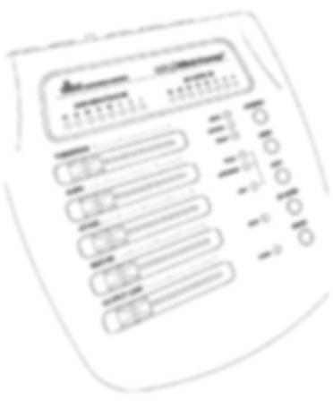
5 MC6 FRONT PANEL GAIN REDUCTION (db) METER: This meter indicates the amount of attenuation of the input signal by the MC6's Compressor, instantaneously displaying the amount of gain reduction achieved.the meter is always active, even when the MC6 is in BYPASS mode. INPUT/OUTPUT LEVEL METER: This 8-stage meter indicates, in db, how far the input or output signal is below clipping or, in other words, headroom. To maximize the signal-to-noise ratio (which results in the cleanest signal) it is desireable to run your input and output levels hot enough that the -3dB (red) LED just flickers on during the highest expected peak levels. If the -3dB LED stays on too much, clipping is occurring and will audibly degrade the sound quality. In this case, turn down the output level of the device feeding the input of the MC6. When the I/O METER switch is engaged (in), the INPUT LED lights and the meter is displaying the input signal.when the I/O METER switch is out, the input LED is off and the meter is displaying the output signal. THRESHOLD CONTROL and LEDs (BELOW/OVEREASY/ABOVE): Adjust this slider left to right to set the threshold of compression. Sliding to the left sets a lower compression threshold and therefore results in more compression for a given signal level. In hard knee mode the threshold of compression is the point at which the compressor begins to compress the dynamic range of the signal. In OverEasy mode, the threshold of compression is roughly the middle of the OverEasy range. The three THRESHOLD LEDs indicate the relationship of the input signal level to the threshold of compression. In hard knee mode, the green LED lights when the signal is BELOW threshold, the red LED lights when the signal is above threshold, and the yellow LED does not light. In OverEasy mode, the green LED lights when the signal is BELOW the OverEasy region, the red LED lights when the signal is above the OverEasy region, and the yellow LED lights when the OVEREASY switch is engaged and the input signal is in the OverEasy range. See Figures 1 and 2 on the next page. The MC6's OverEasy compression permits extremely smooth, natural sounding compression, without artifacts, due to the gradual change of compression around the threshold. With OverEasy compression, input signals begin to gradually activate the MC6's internal gain change circuitry as they approach the THRESHOLD reference level. They do not get fully processed by the RATIO, ATTACK and RELEASE controls until they have passed somewhat above the THRESHOLD reference level. As the signal level passes the THRESHOLD level, processing increases until it is fully processed to the extent determined by the control settings. In hard knee mode, (OverEasy inactive) the MC6 can provide abrupt compression effects as well as hard-limiting applications. Note that when in hard knee mode the yellow OverEasy LED will not light as the input signal passes across the threshold. The signal is either being compressed (over threshold) or it is not being compressed (under threshold). 3
6 OVEREASY SWITCH: The OVEREASY SWITCH toggles the MC6 between the OverEasy and hard knee modes of compression. In OverEasy mode the ratio of compression changes slightly as the signal moves through a threshold range, creating a softer compression effect. This can be very useful on signals that are somethimes hard to tame, like vocals or guitars.the hard knee mode uses the set threshold level as the absolute point at which compression will start to occur at the set ratio amount, depending on the attack and release times set by the user or by the AUTO SWITCH. See Figures 1 and 2 below for the differences between OverEasy and hard knee compression +20 RED Above Threshold 1:1 Unity +20 1:1 OUTPUT LEVEL (db) GREEN Below Threshold 2:1 4:1 20:1 Rotation Point Threshold :1 OUTPUT LEVEL (db) GREEN YELLOW AMBER 2:1 4:1 :1 RED Above Threshold OverEasy Range Below Threshold INPUT LEVEL (db) INPUT LEVEL (db) Figure 1: Hard Knee Compression Curve, and Threshold LEDs. Figure 2: OverEasy Compression Curve, and Threshold LEDs. RATIO CONTROL: Adjust this control to set the amount of compression applied to the input signal. Sliding the control to the right increases the compression ratio from 1:1 (no compression) up to :1 (where the compressor can be set up as a peak limiter, with faster ATTACK settings). When an input signal is above the THRESHOLD setting, the RATIO setting determines the number of decibels by which the input signal must be increased in level to produce a 1dB increase in the signal level at the output of the MC6. A setting of 2:1 indicates an input/output ratio wherein a 2dB increase in signal (above threshold) will produce a 1dB increase in output signal. A setting of :1 indicates that an infinite increase in input level would be required to raise the output level by 1dB. ATTACK AND RELEASE CONTROLS: The ATTACK control sets the amount of time it takes the MC6 to begin compressing a signal once the detector has sensed a signal above threshold. The ATTACK range is from FAST (for a tighter and more noticeable compression effect with very little overshoot) to SLOW (for more delayed, gradual compression). A very fast ATTACK setting will cause the MC6 to act like a peak limiter even though RMS detection circuitry is used. Slower ATTACK settings cause the MC6 to act like an RMS or average-detecting compressor/limiter. The RELEASE control sets how fast the compression circuit returns the input to its original level. The RELEASE rate is from fast (where compression follows the envelope of the program material very tightly) to slow (for very smooth compression). 4
7 There is no absolute right way to set the ATTACK and RELEASE controls. However, in general, you will want them set slow enough to avoid pumping or breathing sounds caused when background sounds are audibly modulated by the dominant signal energy, yet the release must be fast enough to avoid suppression of the desired signal after a sudden transient or loud note has decayed. For low frequency tones (e.g., bass guitar), try setting ATTACK and RELEASE slightly to the right of center. Note: ATTACK and RELEASE controls operate together and in conjunction with the RATIO control as far as how they affect the sound. Changing one control may necessitate changing another setting. OUTPUT GAIN CONTROL: This control sets the output gain of the compressor. Use this control to compensate for signal level loss due to compression and to adjust the nominal output level of the unit.the 44dB control range allows the nominal output level of the MC6 to match a wide variety of equipment levels, from instrument level to pro (+4dBu) level. AUTO AND MODE SWITCHES AND LEDS: The AUTO SWITCH overrides both the ATTACK and RELEASE SLIDERS and enables preset program-dependent attack and release times. There are two different sets of AUTO parameters, or MODES, labeled VOCAL and INSTRUMENT. These two settings are only active when the AUTO SWITCH is engaged (in the in position) and are selectable via the MODE SWITCH. In these settings, the compressor dynamically responds to the input signal (program-dependent) and continuously changes to match its dynamics. The VOCAL mode has a somewhat faster attack and release characteristic ideal for compressing widely dynamic signals, such as vocals.the INSTRUMENT setting has slower attack and release times, ideal for adding sustain to instrument parts without squashing the initial attack of the signal.the LED labeled AUTO is lit when the AUTO SWITCH is engaged, or in the in position.the two modes are then able to be selected via the MODE SWITCH.The LEDs indicating which mode the AUTO setting is using only light in AUTO mode. In the VOCAL mode, enabling the AUTO function duplicates the classic dbx sound of the MC6 s forerunners which have become standards in the industry. Note that the two AUTO settings may be used for applications other than vocals or instruments. They are labeled this way to provide a good starting point for first-time compressor users. I/O METER SWITCH AND LED: Use this switch to select the mode of the I/O meter.with the I/O METER SWITCH in the in position, the I/O meter is in input mode, and the INPUT LED lights to indicate the selection. In input mode the meter shows combined left and right channels audio level after the input gain stage and indicates how many db the signal is below clipping (ie: headroom). When the switch is in the out position, the I/O meter is in output mode and similarly shows the combined left and right channels audio level (headroom) at the output, after all processing has taken place. In output mode, the INPUT LED is not lit. BYPASS SWITCH AND LED: Press this switch in to bypass the front panel controls, effectively disabling the processing of the MC6's compression and gain settings. The input signal is now unaltered by the MC6's controls. BYPASS is especially useful for making comparisons between processed and unprocessed signals. The red BYPASS LED lights when the BYPASS switch is activated. For more information see the section called BYPASS FOOTSWITCH JACK on the next page. 5
8 MC6 REAR PANEL INPUT JACKS: Use 1/4 TS or TRS (unbalanced or balanced) phone plugs to connect to these inputs from your source. The MC6's INPUT jacks accept either balanced or unbalanced signals in LINE mode and unbalanced signals in INST mode. Nominal input level is -10dBV in Line mode, and -20dBV in INSTRUMENT mode. When a source is plugged into the input labeled LEFT (mono), the input signal is routed through both channels and thus appears at both output jacks.this feature can come in handy as an active splitter to send the same signal to two guitar amps, for example. OUTPUT JACKS: The OUTPUT jacks accept 1/4 balanced or unbalanced phone plugs in both LINE and INST. modes, although the outputs are optimized for unbalanced operation when in INST. mode. Nominal output signal level is the same as the nominal input level when the OUTPUT GAIN control is set to the mid-position. Maximum output signal level is +21dBu, typical of professional gear running on a ±15 Volt power supply. OPERATING LEVEL SWITCH: This switch selects between LINE and INSTRUMENT operating levels.when the switch is in the OUT position, a Line operating level is selected. It is optimized for -10dBV, although hotter signals may be processed with a corresponding reduction in headroom (see specifications on page 11). When it is in the IN position, an instrument level operating level is selected. It is optimized for low-level sources (-20dBV) requiring a high (500k½) input impedance.this allows intruments, such as electric guitars,and high impedance unbalanced mics to be plugged directly into the MC6 (typically into the LEFT (mono) input). Note that the operating level switch affects both input and output nominal levels simultaneously. DC POWER CORD RECEPTACLE: Plug the DC power adapter (supplied) into the MC6. Plug the other end into a standard wall receptacle.take care to route power cables away from audio lines.note that the MC6 does not have a power switch. Since power consumption is low, the MC6 may be left on for extended periods of time. If you do not plan to use the MC6 for an extended period of time, unplug it. BYPASS FOOTSWITCH JACK: In addition to the front panel BYPASS SWITCH, the bypass function of the MC6 may be accessed via the rear panel BYPASS FOOTSWITCH. When a standard latching footswitch controller is attached to the BYPASS FOOTSWITCH JACK, the MC6 is toggled in and out of bypass mode.the switch must be one whose 1/4 plug tip is shorted to sleeve when latched. 6
9 When the tip is shorted to the sleeve, compression is active; when the tip is not shorted to the sleeve, the unit is bypassed. The front panel BYPASS LED is activated when the footswitch controller is operating the bypass mode of the MC6. In order for the footswitch to operate, the front panel BYPASS SWITCH must be deactivated, or in the out position. Similarly, the rear panel FOOTSWITCH must be in the shorted position for the front panel BYPASS SWITCH to work. CONNECTING THE MC6 TO YOUR SYSTEM The MC6 can be used with any line-level or intrument level device (see specifications on page 11). Some common examples include mixing consoles, electronic musical instruments, patch bays, and signal processors. For all connections, refer to the following steps: Turn Off all equipment before making any connections. Make connections via 1/4 phone jacks according to your requirements. Typical patch points include: a mixer's channel or subgroup inserts when using the MC6 on individual instruments or tracks; the mixer's main outputs when mixing; an instrument preamp's effects loop when using the MC6 for guitar or bass; main outs of a submixer (i.e., keyboard mixer) as the signal is sent to main mixer; between a DAT's output and an analog cassette input.when using a chain of processors,the MC6 may be placed either before or after effects or dynamics processors. It can also be placed first in a chain of guitar pedal effects, where a guitar may be plugged directly into the MC6 mono input. We recommend you use common sense and experiment with different setups to see which one provides the best results for your needs. Connect the DC power cord (shipped with the unit) to the MC6's rear panel POWER connector and an appropriate AC power source to turn the unit ON. MC6 Outputs insert returns MC6 Inputs insert sends Use the MC6 to compress those pesky individual tracks by inserting it in the insert path of your mixer for a single channel or for a (stereo) linked pair of signals. 7
10 output input input output output input input Use the dbx MC6 Mini- Comp Compressor in your live sound rig by putting it before your other signal processors. Or put it in line before you send to your mixer or recorder. Get that great dbx compression that no other guitar processor or recorder has! input Power-Tip ip: With mono signals like your guitar, use the MC6 as a Y-cable. Both outputs send the same signal when the mono input is used as the only input. This means you can send signal to a recorder AND to an amp/speaker system independent of each other. console main or tape outputs Use the dbx MC6 Mini-Comp Compressor when you record to maximize signal to noise ratio by inserting the MC6 on the main/tape outputs before the signal goes to your multitrack recorder.the MC6 s True RMS Power- Summing will track your stereo image perfectly every time. outputs recorder inputs inputs APPLICATIONS Fattening Kick Drums and Compressing Other Drums Weak, flabby kick drums often have too much boom, and not enough slap.to tighten them up, start with the MC6 adjusted for a medium to high RATIO slider position, adjust the THRESHOLD control so that the GAIN REDUCTION meter shows 15 db of gain reduction, then increase the RATIO if necessary. In OverEasy mode, the MC6 takes slightly longer to react 8
11 than in hard knee mode, and will therefore emphasize the slap at the beginning of the note and reduce the boominess of its body. The MC6 also works well for tightening snare drums and tom toms and can be used with drum machines to effectively alter the character of any electronic drum sound. For drum kit submixes (e.g.,mixing multiple drum tracks to two tracks while using both channels of the MC6 for compression), consider backing off the RATIO (mid position) on each channel to avoid an excess of cymbal splattering. In larger multitracking systems, compress the kick and snare separately. A further possibility is to heavily compress a stereo submix of toms and leave the remaining percussives unaffected. Raising a Signal Out of a Mix Since reducing dynamic range increases the average signal level by a small amount, a single track can be raised out of a mix by boosting its level slightly and applying compression. Start with the middle RATIO position and a relatively low THRESHOLD setting. Adjust both controls as necessary. Compressors have also been used to bring vocals to the forefront of a mix in volume-restricted studios (e.g. home studios). Start by adding a foam windscreen to the mic (if it doesn t have one). Set the RATIO slider 3/4 to the right and the THRESHOLD slider slightly to the left of center.with your mouth approximately 2 inches from the mic, sing the vocal part, but with less volume than normal.use phrasing to give the part some intensity. An equalizer (e.g.,a dbx 242 Parametric Equalizer, dbx 20 or 30 Series Graphic Equalizers) or a vocal effects device (e.g., reverb, delay, distortion) can be added to further define the performance. Note: When compressing a stereo program with the MC6, the factors affecting a compression curve and the actual RATIO and THRESHOLD settings are the same as those previously covered with reference to single channels of program material. However, it will generally be found that large amounts of compression are more audible in a mixed stereo program than they might be on the separate tracks that were mixed to create the program. Smoothing out microphone levels When distance is created between the vocalist and the microphone there will be a variation in the signal level. Start with low compression to smooth out any variations. Limiting also benefits intelligibility by allowing low-level input signals to be reproduced through the system at higher volume. Smoothing out musical instrument levels Compression smooths out the variations of loudness among instruments. Using the MC6 can also increase the instrument s sustain. Compress the instrument s output by adjusting the RATIO and THRESHOLD settings to show between 8 and 12dB of gain reduction with a ratio setting between mid-position and 3/4 to the right. Speaker Protection Compressors are frequently used to prevent excessive program levels from distorting power amps and/or damaging drivers in a sound-reinforcement system (whether you re doing auditorium, church, or club sound engineering, or are a mobile DJ, or like to push the limits of your 9
12 home s audio entertainment center). Set the MC6 for limiting (Hard Knee mode On, with the RATIO slider all the way to the right) and adjust the THRESHOLD to provide 15 db or more of compression (just a few db below the input clip). For low-level signals, the MC6 won t change gain, but if large signals come along, the gain will be reduced to prevent clipping and save sensitive system components from excessive heat buildup or other types of damage. FACTORY SERVICE / WARRANTY The MC6 is an all-solid-state product with components chosen for high performance and excellent reliability. Each MC6 is tested, burned-in and calibrated at the factory and should require no internal adjustment of any type throughout the life of the unit. We recommend that your MC6 be returned to the factory only after referring to the manual and consulting with dbx Customer Service. Our phone number, fax number and address are listed on the back cover of this manual. When you contact dbx Customer Service, be prepared to accurately describe the problem. Know the serial number of your unit. This is printed on a sticker attached to the bottom of the unit. Note: Please refer to the terms of your Limited Two-Year Standard Warranty, which extends to the first end-user. After the warranty expires, a reasonable charge will be made for parts, labor, and packing if you choose to use the factory service facility. In all cases, you are responsible for shipping charges to the factory. dbx will pay return shipping if the unit is still under warranty. Shipping Instructions: Use the original packing material if it is available. Mark the package with the name of the shipper, and with these words in red: DELICATE INSTRUMENT, FRAGILE! Insure the package properly. Ship prepaid, not collect. Do not ship parcel post. We appreciate your feedback. After you have an opportunity to use your new MC6, please complete the Registration Card and return it. This warranty is valid only for the original purchaser and only in the United States. 1.The warranty registration card that accompanies this product must be mailed within 30 days after purchase date to validate this warranty. Proof-of-purchase is considered to be the burden of the consumer. 2. dbx warrants this product, when bought and used solely within the U.S., to be free from defects in materials and workmanship under normal use and service. 3. dbx liability under this warranty is limited to repairing or, at our discretion, replacing defective materials that show evidence of defect, provided the product is returned to dbx WITH RETURN AUTHORIZATION from the factory, where all parts and labor will be covered up to a period of two years.a Return Authorization number must be obtained from dbx by telephone. The company shall not be liable for any consequential damage as a result of the product's use in any circuit or assembly. 4. dbx reserves the right to make changes in design or make additions to or improvements upon this product without incurring any obligation to install the same additions or improvements on products previously manufactured. 5.The foregoing is in lieu of all other warranties, expressed or implied, and dbx neither assumes nor authorizes any person to assume on its behalf any obligation or liability in connection with the sale of this product. In no event shall dbx or its dealers be liable for special or consequential damages or from any delay in the performance of this warranty due to causes beyond their control. 10
13 Inputs Connectors: 1/4 TRS (tip hot, ring cold) Type: Line: Electronically balanced/unbalanced Instrument: Unbalanced Impedance: Stereo Inputs Line: Balanced 20k½, unbalanced 10k½ Instrument: 1Meg½ Mono Input: Line: Balanced 10k½, Unbalanced 5k½ Instrument: 500k½ Max Input Level: Line: +16 dbu balanced or unbalanced Instrument: 0 dbu unbalanced Nominal Input Level: Line: -10dBV (24dB headroom) -2dBu (18dB headroom) +4dBu (12dB headroom) Instrument: -30dBV (28dB headroom) -20dBV (18dB headroom) CMRR: >35dB at 1kHz, typically >50dB Outputs Connectors: 1/4 TRS (tip hot, ring cold) Type: Line: Impedance-balanced/unbalanced Instrument: Unbalanced Impedance: Line: Balanced 4k½, unbalanced 2k½ Instrument: 300½ Max Output Level: Line: +21dBu (into >50kOhm) balanced/unbalanced Instrument: 0dBu (into >50kOhm) Nominal Output Level: Same as nominal input level System Performance Bandwidth: <10Hz to >25kHz, +0/-0.5dB Frequency Response: <1Hz to >60kHz, +0/-3dB Noise: Line: <-97dBu, unweighted, 22kHz measurement bandwidth Instrument: <-105dBu, unweighted, 22kHz measurement bandwidth Dynamic Range: >113dB THD+Noise: Line: 0.008% typical at -10dBV, 1kHz, unity gain Instrument: 0.08% typical at -20dBV, 1kHz, unity gain < 0.5 %, any amount of compression up to 30 db, 1 khz Interchannel Crosstalk: <80dB at 1kHz Compressor Threshold Range: 60dB Ratio: 1:1 to :1 Threshold Characteristic: OverEasy or hard knee with switch and LED Compressor Threshold Meter: 3-segment LED bar graph Below, OverEasy, and Above Attack/Release Characteristic: Manual Mode: AutoDynamic Auto Mode: Automatic Program-Dependent Attack/Release Modes: Manual,Vocal (Auto), and Instrument (Auto) with switch and LED indicators Manual Attack Time: Scalable Program-Dependent: Typically 3dB/msec to 0.04dB/msec Manual Release Time: Scalable Program-Dependent: Typically 250dB/sec to 5dB/sec Program-Dependent Auto Attack Time: Vocal: Typically 15ms for 10dB, 5ms for 20dB, 3ms for 30dB Instrument: Typically 45ms for 10dB, 15ms for 20dB, 9ms for 30dB Program-Dependent Auto Release Time: Vocal: Typically 125dB/sec rate Instrument: Typcially 40dB/sec rate Output Gain: -22 to +22dB Gain Reduction Meter: 8-segment LED bar graph at 1, 3, 6, 10, 15, 20, 25, and 30 db General Bypass: Switch and LED Input/Output Meter: 8-segment tri-color LED headroom bar graph at -30, -25, -20, -15, -12, -9, -6, and -3 db Meter Source: Input level or Output level with switch and LED Power Supply Type: External AC to AC adapter, 820mA Operating Voltage: 100 VAC 50/60Hz; 120 VAC 60Hz; 230 VAC 50Hz; 240 VAC 50Hz Power Consumption: 10 W Physical Dimensions: 1.65 (4.2 cm) H X 5.75 (14.6 cm) W X 6.4 (16.3 cm) D Weight: 1.4lbs. (0.63kg) with power adapter Shipping Weight: 2.1lbs. (0.95kg) Note: Specifications subject to change. 11
14 NOTES 12
15
16 8760 South Sandy Pkwy. Sandy, Utah Phone: (801) Fax: (801) IntÕl Fax: (219) E mail: customer@dbxpro.com World Wide Web: A Harman International Company A 8/11/96
560A 500 SERIES COMPRESSOR/LIMITER OWNER S MANUAL
 500 SERIES COMPRESSOR/LIMITER OWNER S MANUAL Warranty 1. Please register your product online at www.dbxpro.com. Proof-of-purchase is considered to be the responsibility of the consumer. A copy of the original
500 SERIES DE-ESSER OWNER S MANUAL
 500 SERIES DE-ESSER OWNER S MANUAL Warranty 1. Please register your product online at www.dbxpro.com. Proof-of-purchase is considered to be the responsibility of the consumer. A copy of the original purchase
SW 50. Powered Subwoofer with Built-in Stereo Crossover
 Owner s Manual SW 50 ed Subwoofer with Built-in Stereo Crossover Congratulations on your new purchase and welcome to the AudioSource family of satisfied customers. We trust you will continue to enjoy the
POWERED MIXER MPM 4130 OWNER S MANUAL 4 CHANNEL POWERED MIXER
 POWERED MIXER OWNER S MANUAL MPM 4130 4 CHANNEL POWERED MIXER MPM 4130 4 CHANNEL POWERED MIXER Congratulations on your choice of a powered mixer you have purchased one of the finest powered mixers on the
T L Audio. User Manual C1 VALVE COMPRESSOR. Tony Larking Professional Sales Limited, Letchworth, England.
 T L Audio User Manual C1 VALVE COMPRESSOR Tony Larking Professional Sales Limited, Letchworth, England. Tel: 01462 490600. International +44 1462 490600. Fax: 01462 490700. International +44 1462 490700.
Vacuum Tube Preamplifier & Compressor
 Vacuum Tube Preamplifier & Compressor Owner s Manual Version 1.0 WARNING FOR YOUR PROTECTION, PLEASE READ THE FOLLOWING: WATER AND MOISTURE: Appliance should not be used near water (e.g. near a bathtub,
LX20 OPERATORS MANUAL
 LX20 OPERATORS MANUAL CONTENTS SAFETY CONSIDERATIONS page 1 INSTALLATION page 2 INTRODUCTION page 2 FIRST TIME USER page 3 SYSTEM OPERATING LEVELS page 3 FRONT & REAR PANEL LAYOUT page 4 OPERATION page
DOD OWNER'S MANUAL 866 SERIES II GATED COMPRESSOR/LIMITER SIGNAL PROCESSORS
 DOD SIGNAL PROCESSORS 866 SERIES II GATED COMPRESSOR/LIMITER OWNER'S MANUAL 866 SERIES II GATED COMPRESSOR/LIMITER INTRODUCTION : The DOD 866 Series II is a stereo gated compressor/limiter that can be
MODEL Operation Manual
 MODEL 1066 Operation Manual IMPORTANT SAFETY INFORMATION The symbols shown above are internationally accepted symbols that warn of potential hazards with electrical products. The lightning flash with arrowpoint
Dual Compressor/Limiter/Gate
 Dual Compressor/Limiter/Gate User Manual Professional Audio Equipment IMPORTANT SAFETY INFORMATION The symbols shown above are internationally accepted symbols that warn of potential hazards with electrical
TEC4X. Multi-Effects Processor. A Harman International Company
 TEC4X TEC4X Multi-Effects Processor USER GUIDE USER GUIDE A Harman International Company DECLARATION OF CONFORMITY Manufacturer s Name: Manufacturer s Address: DOD Electronics 8760 S. Sandy Parkway Sandy,
FOOT CONTROLLER USER S GUIDE
 FOOT CONTROLLER USER S GUIDE DECLARATION OF CONFORMITY Manufacturer s Name: Manufacturer s Address: DigiTech 8760 S. Sandy Parkway Sandy, Utah 84070, USA declares that the product: Product name: Control
PRO VLA PROFESSIONAL TWO CHANNEL VACTROL/TUBE LEVELING AMPLIFIER
 PRO VLA PROFESSIONAL TWO CHANNEL VACTROL/TUBE LEVELING AMPLIFIER USER S GUIDE TABLE OF CONTENTS Introduction 2 Registration 2 Features 3 Overview 4 Setting Up 5 Unpacking 5 AC Power Hookup 5 Audio Connections
HPA-8 8 Channel Headphone Amplifier. Owner s Manual
 HPA-8 8 Channel Headphone Amplifier Owner s Manual Contents Features... 2 Warning... 3 Installation... 4 Panel Connections, Controls and Indicators... 5 Using the HPA-8... 6 Specifications... 7 With extensive
Pro VLA II PROFESSIONAL TWO CHANNEL VACTROL /TUBE LEVELING AMPLIFIER USER S GUIDE
 Pro VLA II PROFESSIONAL TWO CHANNEL VACTROL /TUBE LEVELING AMPLIFIER USER S GUIDE IMPORTANT SAFETY INSTRUCTIONS READ FIRST This symbol, wherever it appears, alerts you to the presence of uninsulated dangerous
DMP3. Users Manuual. Ver. # DMP
 TM AUDIO DMP3 Users Manuual Ver. # DMP3-121701 Table of Contents Introduction.......................................................2 DMP3 Features....................................................2
MX-206 Stereo Microphone Mixer. Operating Manual
 MX-206 Stereo Microphone Mixer Operating Manual ASHLY AUDIO INC. 847 Holt Road Webster, NY 14580-9103 Phone: (585) 872-0010 Toll-Free: (800) 828-6308 Fax: (585) 872-0739 www.ashly.com Operating Manual
TUBE MIX FIVE CHANNEL MIXER WITH USB AND ASSIGNABLE 12AX7 TUBE. User's Manual
 TUBE MIX FIVE CHANNEL MIXER WITH USB AND ASSIGNABLE 12AX7 TUBE User's Manual IMPORTANT SAFETY INSTRUCTIONS READ FIRST This symbol, wherever it appears, alerts you to the presence of uninsulated dangerous
DP1 DYNAMIC PROCESSOR MODULE OPERATING INSTRUCTIONS
 DP1 DYNAMIC PROCESSOR MODULE OPERATING INSTRUCTIONS and trouble-shooting guide LECTROSONICS, INC. Rio Rancho, NM INTRODUCTION The DP1 Dynamic Processor Module provides complete dynamic control of signals
Summit Audio Model TLA-50 Tube Leveling Amplifier
 Summit Audio Model TLA-50 Tube Leveling Amplifier ATTACK FAST SLOW MEDIUM 3 4 5 6 7 TUBE LEVELER 40 60 80 100 VU 3 4 5 6 TLA-50 7 FAST SLOW RELEASE OUTPUT RED. METER 2 1 0 10 GAIN 9 8 7 5 3 1 0 1 2 +3
PROFESSIONAL 2 CHANNEL SOLID-STATE MIC / LINE PREAMPLIFIER USER S MANUAL
 PROFESSIONAL 2 CHANNEL SOLID-STATE MIC / LINE PREAMPLIFIER USER S MANUAL SAFETY INSTRUCTIONS This symbol, wherever it appears, alerts you to important operating and maintenance instructions in the accompanying
FAT MAN FAT 1. TLAudio. user manual. stereo valve compressor. TL Audio Limited, Sonic Touch, Iceni Court, Icknield Way, Letchworth, SG6 1TN England
 user manual FAT MAN by TLAudio TL Audio Limited, Sonic Touch, Iceni Court, Icknield Way, Letchworth, SG6 1TN England Tel: +44 (0)1462 680888 Fax: +44 (0)1462 680999 email: info@tlaudio.co.uk web: http://www.tlaudio.co.uk
HeadAmp 4 Pro. User s Manual. Project Series. Five Channel Headphone Amp with Listen and Talkback
 HeadAmp 4 Pro Five Channel Headphone Amp with Listen and Talkback Project Series User s Manual IMPORTANT SAFETY INSTRUCTIONS READ FIRST This symbol, wherever it appears, alerts you to the presence of
O w n e r s M a n u a l
 Owner s Manual Manufacturer s Name: DigiTech Manufacturer s Address: 8760 S. Sandy Parkway Sandy, Utah 84070, USA declares that the product: Product name: istomp Product option: all (requires Class II
USER MANUAL MX102 & MX1202
 USER MANUAL MX102 & MX1202 WWW.PULSE-AUDIO.CO.UK 1 SAVE THESE SAFETY INSTRUCTIONS Thank you for purchasing our product. To assure the optimum performance, please read this manual carefully and keep it
ieq ieq-15 ieq-31 Dual Channel Digital Graphic EQ/Limiter w/type V NR and AFS User Manual
 ieq Dual Channel Digital Graphic EQ/Limiter w/type V NR and AFS ieq-15 ieq-31 User Manual IMPORTANT SAFETY INSTRUCTIONS WARNING FOR YOUR PROTECTION READ THE FOLLOWING: KEEP THESE INSTRUCTIONS HEED ALL
C Class Signal Processors
 -5-3 -2-7 -1 0-10 -20 +4 VU SAMSON OPTICAL COMPRESSOR A U D I O C Class Signal Processors Safety Instructions Caution: To reduce the hazard of electrical shock, do not remove cover or back. No user serviceable
COMPRESSOR LIMITER MANUAL VER See the next page for startup switch settings E5th street Superior WI USA davehilldesigns.
 COMPRESSOR LIMITER MANUAL VER 1.1 201200219 2117 E5th street Superior WI USA 54880 davehilldesigns.com See the next page for startup switch settings 2012 Dave Hill Designs Start Up Settings 2 Safety Information
Passive Four Channel Stereo/Mono Mixer/Splitter. Artcessories. User's Manual
 Passive Four Channel Stereo/Mono Mixer/Splitter Artcessories User's Manual IMPORTANT SAFETY INSTRUCTION READ FIRST This symbol, whenever it appears, alerts you to the presence of uninsulated dangerous
DM900 BLUE DOG OWNER S MANUAL
 Professional Disc Jockey Products DM900 BLUE DOG OWNER S MANUAL NUMARK INDUSTRIES 11 Helmsman Road, North Kingstown, RI 02852 http://www.numark.com CONGRATULATIONS! You have purchased the DM900 Blue Dog
DF330 UNIVERSAL NOISE FILTER OPERATORS MANUAL
 DF330 UNIVERSAL NOISE FILTER OPERATORS MANUAL CONTENTS SAFETY CONSIDERATIONS page 1 INTRODUCTION page 2 INSTALLATION page 3 CONTROL DESCRIPTIONS page 5 High Pass filter page 5 Expander page 5 Filter page
Tube MP/C. User s Manual
 Tube MP/C User s Manual IMPORTANT SAFETY INSTRUCTIONS READ FIRST This symbol, wherever it appears, alerts you to the presence of uninsulated dangerous voltage inside the enclosure. Voltage that may be
MULTI PROCESSOR OPERATION MANUAL
 MULTI PROCESSOR OPERATION MANUAL Version - V1 April 2000 Page 2 CONTENTS 1. Introduction 3 2. Installation 4 2.1 Inspection and un-packing 4 2.2 Operating environment 4 2.3 CE standards 4 2.4 Power requirements
CLASSIC SERIES POWERED SUBWOOFERS
 O P E R A T I O N M A N U A L CLASSIC SERIES POWERED SUBWOOFERS SAFETY INSTRUCTIONS.............. 2 WARRANTY INFORMATION........... 3 CONTROL DESCRIPTIONS............ 4 CONNECTING SUBWOOFER...........
PL-2 Analog Peak Limiter Manual
 PL-2 Analog Peak Limiter Manual Features Two independent channels with stereo link JFET (hard) and MOSFET (soft) peak limiting modes Limiter circuit 'switched out' of the signal path when below threshold
382isw Sonic Maximizer. User Guide and Reference Manual
 382isw Sonic Maximizer User Guide and Reference Manual For your protection, please read these safety instructions completely before operating the appliance, and keep this manual for future reference. Carefully
English. User Manual sub8 Subwoofer SUBWOOFER. Supporting your digital lifestyle
 English User Manual sub8 Subwoofer U SUBWOOFER Supporting your digital lifestyle Table of Contents Important Safety Precautions........ 2 Introduction / What s in the Box?...... 3 Front & Rear Panels............
DL241 DUAL AUTO COMPRESSOR CONTENTS. SAFETY CONSIDERATIONS page 1. INTRODUCTION page 2. INSTALLATION page 3. CONTROL DESCRIPTIONS page 5
 DL241 DUAL AUTO COMPRESSOR OPERATORS MANUAL CONTENTS SAFETY CONSIDERATIONS page 1 INTRODUCTION page 2 INSTALLATION page 3 CONTROL DESCRIPTIONS page 5 OPERATION page 8 IF A FAULT DEVELOPS page 10 CONTACTING
GEQ Series Graphic Equalizers
 GEQ Series Graphic Equalizers Owner s Manual LOW CUT EQ ON OFF +2 +13-5 63 125 315 8 25 63 1.6K 4K 25 4 8 16 4 1K 2K 5K 1K 2 32 5 1 2 5 1.25K 2.5K 6.3K 12.5K 3.15K 8K 16K 2K POWER GEQ 131 31 BAND GRAPHIC
IMPORTANT SAFETY INSTRUCTIONS
 IMPORTANT SAFETY INSTRUCTIONS When using this electronic device, basic precautions should always be taken, including the following: 1. Read all instructions before using the product. 2. Do not use this
USB Phono Plus. Project Series USER S MANUAL. Audiophile Computer Interface
 USB Phono Plus Audiophile Computer Interface Project Series USER S MANUAL IMPORTANT SAFETY INSTRUCTION READ FIRST This symbol, whenever it appears, alerts you to the presence of uninsulated dangerous voltage
Recording to Tape (Analogue or Digital)...10
...10") c o n t e n t s DUAL MIC-PRE Green Dual Mic Pre (introduction).............................4 Section (i): Setting Up Power Connections...........................................4 Power Supply................................................5
c o n t e n t s DUAL MIC-PRE Green Dual Mic Pre (introduction).............................4 Section (i): Setting Up Power Connections...........................................4 Power Supply................................................5
LIGHT COPILOT II. elationlighting.com Internet:
 LIGHT COPILOT II E-mail: info@ elationlighting.com Internet: http://www.elationlighting.com 1 Introduction Thank you for your purchase of the LIGHT COPILOT II. The LIGHT COPILOT II is an intelligent lighting
XO-231 USER S MANUAL. Crossover ENGLISH
 XO-231 Crossover ENGLISH USER S MANUAL IMPORTANT SAFETY INSTRUCTIONS For your own safety you should read this section in full first! Risk of electrical shock! Connect the device only to a properly wired
MODEL 160A COMPRESSOR LIMITER. A Harman International Company
 MODEL 160A COMPRESSOR LIMITER A Harman International Company CAUTION RISK OF ELECTRIC SHOCK DO NOT OPEN ATTENTION: RISQUE DE CHOC ELECTRIQUE - NE PAS OUVRIR WARNING: TO REDUCE THE RISK OF FIRE OR ELECTRIC
Vintage Audio MSL-MK2. Quad VCA Buss Compressor
 Vintage Audio MSL-MK2 Quad VCA Buss Compressor Vintage Audio MSL-mk2 Quad VCA Compressor ++ Congratulations on your purchase of your new Vintage Audio MSL-mk2 Quad VCA Buss compressor. The MSL-mk2 is based
Utility Amplifier GA6A Model
 Utility Amplifier GA6A Model Installation and Use Manual 2004 Bogen Communications, Inc. All rights reserved. Specifications subject to change without notice. 54-5757-03D 1503 NOTICE: Every effort was
The Dangerous Music D-Box user s operating guide
 The Dangerous Music D-Box user s operating guide Thank you for choosing products from the exciting line of Dangerous Music recording equipment. Many years of dependable and trouble-free service can be
~ Instruction Manual ~
 ~ DJ-5 Professional Preamp mixer ~ 0 0 0 0 10 10 10 10 EVE MASTE GAIN GAIN 0 10 CUE EVE CH 1 CH 2 CUE PAN INE INE POWE FADE STAT FADE STAT HEADPHONES ~ Instruction Manual ~ ~ Important Safety Instructions
User Guide and Reference Manual
 User Guide and Reference Manual i TABLE OF CONTENTS Important Safeguards i BBE Process Explained 1 Product Description 2 Applications 2 Front Panel Controls 3 Rear Panel Connections 4 Specifications 5
882i Sonic Maximizer. User Guide and Reference Manual
 882i Sonic Maximizer User Guide and Reference Manual For your protection, please read these safety instructions completely before operating the appliance, and keep this manual for future reference. Carefully
3124mb+ All Discrete 4 Channel Mic/Instrument Preamplifier with Stereo Mixer Operator s Manual
 3124mb+ All Discrete 4 Channel Mic/Instrument Preamplifier with Stereo Mixer Operator s Manual Written by Carl J Houde 2015 Table of Contents 1.0 Introduction... 3 2.0 Overview... 4 2.1 3124mb+ Features
IMPORTANT SAFETY INSTRUCTION READ FIRST
 IMPORTANT SAFETY INSTRUCTION READ FIRST This symbol, whenever it appears, This symbol, wherever it appears, alerts alerts you to the presence of uninsulated you to important operating and maintenance dangerous
CFX 12 (12X4X1) 8 mic/line channels, 2 stereo line channels. CFX 16 (16X4X1) 12 mic/line channels, 2 stereo line channels
 8 mic/line channels, 2 stereo line channels. CFX 16 (16X4X1) 12 mic/line channels, 2 stereo line channels") COMPACT CFX MIXERS COMPACT SOUND REINFORCEMENT MIXERS WITH EFX FOR THE GIGGING MUSICIAN THREE MODELS CFX 12 (12X4X1) 8 mic/line channels, 2 stereo line channels CFX 16 (16X4X1) 12 mic/line channels, 2
COMPACT CFX MIXERS COMPACT SOUND REINFORCEMENT MIXERS WITH EFX FOR THE GIGGING MUSICIAN THREE MODELS CFX 12 (12X4X1) 8 mic/line channels, 2 stereo line channels CFX 16 (16X4X1) 12 mic/line channels, 2
MM-15USB Mini mixer. Owner s Manual
 MM-15USB Mini mixer Owner s Manual Contents Features... 2 Warning... 3 Installation... 4 1. Inspection... 4 2. Power Connection... 4 Controls & Connections... 5 1. Channel Section... 5 2. Main Control
CM4-BT. Compact Mixer with Bluetooth UK User Manual
 CM4-BT Compact Mixer with Bluetooth 170.804UK User Manual Caution: Please read this manual carefully before operating Damage caused by misuse is not covered by the warranty Introduction: Thank you for
Chameleon Labs Model 7720
 Chameleon Labs Model 7720 Stereo Compressor Owner s Manual 704 228 th Avenue NE, # 826 Sammamish, WA 98074 206-264-7602 www.chameleonlabs.com Revision C - December, 2007 UNPACKING AND INSPECTION Carefully
JamMan Express XT Stereo Looper w/jamsync
 JamMan Express XT Stereo Looper w/jamsync Owner s Manual IMPORTANT SAFETY STRUCTIONS WARNG FOR YOUR PROTECTION READ THE FOLLOWG: KEEP THESE STRUCTIONS HEED ALL WARNGS The symbols shown above are internationally
VACUUM TUBE COMPRESSOR
 1969 VACUUM TUBE COMPRESSOR OPERATORS MANUAL CONTENTS SAFETY CONSIDERATIONS page 1 INTRODUCTION page 2 APPLICATIONS page 2 INSTALLATION page 3 CONTROL DESCRIPTIONS: page 5 Compressor page 5 Microphone
HP6E Operating Manual. August 2012
 HP6E Operating Manual August 2012 SAFETY INSTRUCTIONS CAUTION: To reduce the risk of electrical shock, do not remove the cover or rear panel of this unit. No user serviceable parts inside. Please refer
LTO R. User's Manual AMX-80 7-CHANNEL MIXING CONSOLE. Version 2.0 MARCH 2007 English
 LTO R AMX-0 7-CHANNEL MIXING CONSOLE User's Manual www.altoproaudio.com Version 2.0 MARCH 2007 English IMPORTANT SAFETY INSTRUCTION CAUTION RISK OF ELECTRIC SHOCK DO NOT OPEN TO REDUCE THE RISK OF ELECTRIC
1812R Blues King 12. User Manual
 1812R Blues King 12 User Manual All contents c Absara Audio LLC 2018 1. Important Safety Information The triangle surrounding an exclamation mark alerts users to the presence of important warnings or information.
EUROPA I PREAMPLIFIER MANUAL VER E5th street Superior WI USA davehilldesigns.com
 EUROPA I PREAMPLIFIER MANUAL VER 1.04 20120521 2117 E5th street Superior WI USA 54880 davehilldesigns.com See the next page for startup switch settings 2011, 2012 Dave Hill Designs Start Up Settings 2
PROJECT CHANNEL ESSENTIAL CHANNEL STRIP. Owner s Manual
 PROJECT CHANNEL ESSENTIAL CHANNEL STRIP Owner s Manual SAFETY DECLARATIONS TABLE OF CONTENTS CAUTION: For protection against electric shock, do not remove the cover. No user serviceable parts inside. WARNING:
4 PORT HDMI SWITCH
 4 PORT HDMI SWITCH 1518896 IMPORTANT SAFEGUARDS OF HDMI SWITCH PRODUCTS PLEASE READ CAREFULLY THE FOLLOWING SAFEGUARDS THAT ARE APPLICABLE TO YOUR EQUIPMENT 1. Read instructions - All the safety and operating
PRO MPA II. ART PRO MPA II Microphone Preamplifier USER S GUIDE
 PRO MPA II ART PRO MPA II Microphone Preamplifier USER S GUIDE IMPORTANT SAFETY INSTRUCTIONS READ FIRST This symbol, wherever it appears, alerts you to the presence of uninsulated dangerous voltage inside
Trace Elliot Transit B Bass Instrument Preamp
 Trace Elliot Transit B Bass Instrument Preamp Owner s Manual FCC Compliancy Statement This device complies with Part 15 of the FCC rules. Operation is subject to the following two conditions: (1) this
AutoVelocity Dynamics and the dbx 160SL. White Paper
 AutoVelocity Dynamics and the dbx 160SL White Paper Many audio compressors employ an Auto mode to set the attack and release of the VCA so that the compressor will be well behaved when used in a variety
Oxygen ORDERCODE D2150
 Oxygen ORDERCODE D2150 Congratulations! You have bought a great, innovative product from DAP Audio. The DAP Audio Oxygen brings excitement to any venue. Whether you want simple plug-&-play action or a
RMX-44 & RMX-62 MIXING MATRIX. Installation & Operation Manual
 RMX-44 & RMX-6 MIXING MATRIX Installation & Operation Manual TABLE OF CONTENTS RMX-44 & RMX-6 INTRODUCTION... RMX-44 CALLOUTS... RMX-44 BLOCK DIAGRAM... RMX-6 CALLOUTS... 4 RMX-6 BLOCK DIAGRAM... 5 RMX-44
SyncGen. User s Manual
 SyncGen User s Manual 1 IMPORTANT SAFETY INSTRUCTION READ FIRST This symbol, whenever it appears, alerts you to the presence of uninsulated dangerous voltage inside the enclosure-voltage that may be sufficient
Introduction SAFETY PRECAUTIONS. Contents
 0 0 0 0 9 8 7 6 0 0 9 8 7 6 0 0 9 8 7 6 0 Contents Introduction Safety Precautions Connections System Overview Controls in Detail Inputs Master 7 Advanced Features 8 Initial Setting Up 9 Applications 0
USERS MANUAL. Version , PreSonus Audio Electronics, Incorporated. All rights reserved.
 S M A R T C O M P R E S S O R USERS MANUAL Version 1.0 1997, PreSonus Audio Electronics, Incorporated. All rights reserved. W A R R A N T Y PreSonus Limited Warranty PreSonus Audio Electronics Inc. warrants
Welcome to compressor wonderland!
 xpressor 500 Welcome to compressor wonderland! First of all, we would like to thank you for picking the xpressor 500 as your new dynamics tool - a very good choice indeed. We believe this module is the
Optical Compressor Owner s Manual Rev A all contents Grace Design/ Lunatec LLC
 Optical Compressor Owner s Manual Rev A all contents Grace Design/ Lunatec LLC info@gracedesign.com / www.gracedesign.com 2434 30th Street, Boulder, CO 80301 USA tel 303.443.7454 fax 303.444.4634 Welcome
OPERATOR S MANUAL CONTENTS
 DRAWMER Dual Channel Vacuum Tube Compressor OPERATOR S MANUAL CONTENTS Warranty........................................................... 2 Safety Consideration................................................
TS2.8 Sub OWNER S MANUAL
 TS2.8 Sub OWNER S MANUAL TS2.8 Sub CONTENTS IMPORTANT SAFETY INSTRUCTIONS 03 WARNINGS 03 FUSE PROTECTION 04 WARNING: STRONG MAGNETIC FIELD 04 EMC / EMI 04 ECODESIGN STANDBY POWER CONSUMPTION 04 WARRANTY
Technical Specifications
 INSTALLATION SHEET AND OPERATORS MANUAL General Description: The is a mixer/preamplifier that includes 6 channels that each include a microphone input at screw terminals and an aux input at an RCA jack.
CR-6 MIXER USER MANUAL ENGLISH. Order Code: MIXE01
 CR-6 MIXER P R O F E S S I O N A L 1 9 R A C K M I X E R Order Code: MIXE01 w w w. p r o l i g h t. c o. u k USER MANUAL ENGLISH WARNING FOR YOUR OWN SAFETY, PLEASE READ THIS USER MANUAL CAREFULLY BEFORE
AM-4 Audio Monitor. Videoquip Research Limited 595 Middlefield Road, Unit #4 Scarborough, Ontario, Canada. MIV 3S2
 AM-4 Audio Monitor Videoquip Research Limited 595 Middlefield Road, Unit #4 Scarborough, Ontario, Canada. MIV 3S2 (416) 293-1042 1-888-293-1071 www.videoquip.com AM-4 4 channel Analog, AES3 Digital, SDI
OPERATIONS MANUAL FOR EDISON PROFESSIONAL Professional ABS Molded Loudspeaker M4000
 M4000 Introduction: Congratulations on your purchase of an M-4000 powered loudspeaker, engineered and manufactured by BriteLite Enterprises. The M-4000 includes a high-output compression driver, and 15
TDM 24CX-2 24CX-3 24CX-4 ELECTRONIC CROSSOVER OWNER S MANUAL A U D I O
 TDM A U D I O 24CX-2 24CX-3 24CX-4 ELECTRONIC CROSSOVER OWNER S MANUAL TDM AUDIO INC. 7270 BELLAIRE AVE. NORTH HOLLYWOOD, CA 91605 (818) 765-6200 TDMAUDIO.COM IMPORTANT! *** Read Before Using *** CAUTION:
ALESIS NanoCompressor. Reference Manual
 ALESIS NanoCompressor Reference Manual Introduction INTRODUCTION Thank you for purchasing the Alesis NanoCompressor Dynamics Processor. To take full advantage of the NanoCompressor s functions, and to
BISON 500 USER'S MANUAL. IGS Audio Igor Sobczyk 3 Maja 76d, Mysłowice, Poland ph:
 BISON 500 USER'S MANUAL IGS Audio Igor Sobczyk 3 Maja 76d, 41-400 Mysłowice, Poland e-mail: igs@o2.pl ph: +48 601 597 592 www.igsaudio.com Please read all of the following instructions and save them or
User Manual SONIC ULTRAMIZER SU9920. Ultimate Stereo Sound Enhancement Processor
 User Manual SONIC ULTRAMIZER SU9920 Ultimate Stereo Sound Enhancement Processor 2 SONIC ULTRAMIZER SU9920 User Manual Table of Contents Thank you... 2 Important Safety Instructions... 3 Legal Disclaimer...
Vintage Audio MSL. Quad VCA Buss Compressor
 Vintage Audio MSL Quad VCA Buss Compressor Vintage Audio MSL Quad VCA Compressor Congratulations on your purchase of your new Vintage Audio MSL Quad VCA Buss compressor. The MSL is based on the standard
IMPORTANT SAFETY INSTRUCTION READ FIRST
 IMPORTANT SAFETY INSTRUCTION READ FIRST This symbol, whenever it appears, This symbol, wherever it appears, alerts alerts you to the presence of uninsulated you to important operating and maintenance dangerous
M A S T E R S E C T I O N. User Manual
 M A S T E R S E C T I O N User Manual Version 1.02: July 2007 Contents. Safety Information.... 3 Welcome.... 4 Connections.... 5 A Basic Set-up 5 Setting Up.... 7 Adjusting Input Levels 7 Taking Account
CMX-DSP Compact Mixers
 CMX-DSP Compact Mixers CMX4-DSP, CMX8-DSP, CMX12-DSP Introduction Thank you for choosing a Pulse CMX-DSP series mixer. This product has been designed to offer reliable, high quality mixing for stage and/or
Model 1606 Super. User Manual
 Model 1606 Super User Manual All contents c Absara Audio LLC 2014 1. Important Safety Information The triangle surrounding an exclamation mark alerts users to the presence of important warnings or information.
Overview. A 16 channel frame is shown.
 Overview A 16 channel frame is shown. 22 Mono Input Channel 1 - MIC INPUT The mic input accepts XLR-type connectors and is designed to suit a wide range of BALANCED or UNBALANCED signals. Professional
SAFETY PRECAUTIONS. The SPIRIT FX16 mixer must only be connected through the Power Supply supplied:
 INTRODUCTION Thank you for purchasing an FX16 mixer, brought to you with pride by the SPIRIT team of Andy, Colin, Chris, Simon, Mukesh, Graham, Martin, Paul, Tony and Peter, with the support of many others
OWNER S MANUAL EVOLUTION SERIES POWERED SUBWOOFER ES-SUB-EVO6-100
 OWNER S MANUAL EVOLUTION SERIES POWERED SUBWOOFER ES-SUB-EVO6-100 Important Safety Instructions CAUTION RISK OF ELECTRIC SHOCK! DO NOT OPEN! ATTENTION! RISQUE DE CHOC! ÉLECTRIQUE PAS OUVRIR! The lightning
GIULIA Y. combo amplifier for acoustic instruments
 GIULIA Y combo amplifier for acoustic instruments IMPORTANT SAFETY INSTRUCTIONS THE LIGHTNING FLASH WITH ARROWHEAD SYMBOL, WITHIN AN EQUILATERAL TRIANGLE, IS INTENDED TO ALERT THE USER TO THE PRESENCE
Table of Contents. Introduction 2 C valve Features 3. Controls and Functions 4-5 Front Panel Layout 4 Rear Panel Layout 5
 Safety Instructions Table of Contents Introduction 2 C valve Features 3 Controls and Functions 4-5 Front Panel Layout 4 Rear Panel Layout 5 Operating the C valve 6-13 Setting Up the C valve 6-7 Setting
POWERED MIXER OWNER S MANUAL. SPM Channel Stereo Powered Mixer
 POWERED MIXER OWNER S MANUAL SPM-4250 4-Channel Stereo Powered Mixer SPM-4250 4-Channel Stereo Powered Mixer Congratulations on your choice of the NADY AUDIO SPM-4250 Stereo Powered Mixer you have purchased
STAGE 250. Owner s Manual TRANSPORTABLE PA WITH BUILT-IN MIXER AND 24 BIT EFFECTS
 STAGE 250 Owner s Manual TRANSPORTABLE PA WITH BUILT-IN MIXER AND 24 BIT EFFECTS Important Safety Instructions For your own safety you must read this section in full first! Intended use This device is
Ashly Audio Inc. 847 Holt Road, Webster, NY Toll Free (800) , Telephone (585) , FAX (585)
 , Telephone (585) , FAX (585)") XR 1001 Electronic Crossover Operating Manual U U U U U U db Hz db Hz Ashly Audio Inc. 847 Holt Road, Webster, NY 14580-9103 Toll Free (800) 828-6308, Telephone (585) 872-0010, FAX (585) 872-0739 www.ashly.com
XR 1001 Electronic Crossover Operating Manual U U U U U U db Hz db Hz Ashly Audio Inc. 847 Holt Road, Webster, NY 14580-9103 Toll Free (800) 828-6308, Telephone (585) 872-0010, FAX (585) 872-0739 www.ashly.com
MANUAL ENGLISH Core Club Ordercode: D2314
 MANUAL ENGLISH Core Club Ordercode: Highlite International B.V. Vestastraat 2 6468 EX Kerkrade the Netherlands Table of contents Warning... 2 Unpacking Instructions... 2 Safety Instructions... 2 Operating
TABLE OF CONTENTS. 1) Introduction 2. 2) Unpacking the Ares 2. 3) Installing the Ares in your system 3. 4) Setting the Operational Parameters 4
 Introduction 2. 2) Unpacking the Ares 2. 3) Installing the Ares in your system 3. 4) Setting the Operational Parameters 4") TABLE OF CONTENTS 1) Introduction 2 2) Unpacking the Ares 2 3) Installing the Ares in your system 3 4) Setting the Operational Parameters 4 5) High Output MM/MC Cartridge Setup 6 6) Medium Output Cartridge
TABLE OF CONTENTS 1) Introduction 2 2) Unpacking the Ares 2 3) Installing the Ares in your system 3 4) Setting the Operational Parameters 4 5) High Output MM/MC Cartridge Setup 6 6) Medium Output Cartridge