PHI 5000 VersaProbe TM Operator s Guide
|
|
|
- Lawrence Benson
- 6 years ago
- Views:
Transcription
 is a registered trademark of ULVAC-PHI, INC.")
1 PHI 5000 VersaProbe TM Operator s Guide Part No Rev. A Copyright 2006 ULVAC-PHI, INC. 370 Enzo, Chigasaki, JAPAN The PHI logo ( ) is a registered trademark of ULVAC-PHI, INC. Physical Electronics, PHI, MultiPak and Watcher are trademarks of ULVAC-PHI, INC.. All other trademarks are the property of their respective owners.
2 PHI XPS Reservation/Use Policy Reservations can be made up to One Week in advance. A Maximum of 4 hours/session can be reserved between 9am and 5pm Monday thru Friday. There is no restriction on reservation during evenings, early mornings or weekends. You need to arrive at the instrument at the beginning of your reserved time (or earlier). If you do not show up at the instrument and enable Badger within 30 minutes of the start of your reservation another user can consider this a NO SHOW and take that time slot for themselves. If you cancel or cannot use your reserved time, send an to lamxps_users@lists.stanford.edu letting other users know the time slot has been released. messages releasing a reservation need to be sent REGARDLESS of the day or time the instrument is being released. Send an to lam-xps_users@lists.stanford.edu if you finish running the instrument 30 minutes or more prior to the end of your reserved time letting other users know there is open time on the instrument. Failure to follow any of these rules can result in you being charged for reserved but unused instrument time. To receive notifications of released time and updates on instrument maintenance go to lists.stanford.edu and subscribe to lam-xps_users.
3 PHI VersaProbe Scanning XPS System Overview The Main Operating Software is PHI Summitt. It controls the movement of the sample stage, the analysis set-up and acquisition and the control of the ion gun and neutralizer gun. Vacuum Watcher is a separate program that interacts with the PHI Summitt program and is used in conjunction with Summitt to load and transfer samples and to differentially pump the ion gun for ion sputtering. PHI MultiPak is a data reduction program used both for XPS and AES to process spectra, images and profiles acquired on the XPS or AES system. A copy of this program is on the XPS and the AES instrument computers as well as on the stand alone Dell Dimensions offline computer in the lab. The Summitt and Vacuum Watcher programs should always be up and running on the instrument. Do not close these programs without specific instructions from one of the lab supervisors. All three programs can be found on the desktop and on the toolbar at the bottom of the screen. Features The VersaProbe XPS is capable of x-ray beam spot sizes from 10um to 100um and a High Power setting with a beam spot of roughly 1400 x 300um. Secondary electron images can be acquired to locate specific analysis areas on samples with specific features to be analyzed. Computer controlled X, Y, Z, Tilt and Rotate stage control. Auto Z alignment for optimization of x-ray impact and electron extraction. Angle resolved measurements can be done to analyze ultra thin films. Ion sputtering can be done to analyze thicker films or remove surface contamination. Dual beam (electrons and ions) charge neutralization of insulating samples.
4 Sample Introduction The Vacuum Watcher Program controls the vacuum valve functions required to load and transfer samples in and out of the instrument. Each sample mount has a molybdenum mask secured by small flat-head screws. Loosen the screws and slip the sample under the mask. You can use the mask to secure the sample in place, and you can see it on the image monitor to help you navigate on the sample. If using a mask is not favorable the CuBe clips or silver paste can be used to secure the sample. When working with silver paste use as small an amount as possible to secure the sample. Ensure the silver paste has dried completely prior to introduction into the vacuum system. In the Vacuum Watcher Program, the Backfill Into button is used to vent the intro chamber. The Sample holder is mounted on the end of the transfer arm fork, the chamber cap replaced
 position.")
5 and the Pump Intro button is used to pump out the intro chamber. This pumping process takes approximately 5 minutes. After the Vacuum Watcher program indicates the pump intro is complete move the stage to the transfer (Home) position. Go to the SUMMITT Image window and the Stage tab and click the Intro button (Figure below). An Intro dialog box opens (Figure below) and the sample stage will move to the home position. Do not click Up [Z] yet.
6 Push the Transfer Sample Button in Watcher. A Watcher message pops up. Click Yes on the Watcher Task Message ("Pump Intro Complete. Transfer Sample?") (Figure below). V1 will open. If No is selected the sample transfer will be aborted and V1 will not be opened. When V1 opens another Watcher Task Message ("Introduce the sample now.") will popup (Figure below), click OK. ATTENTION: Do not move the stage while moving the intro rod. While watching through the viewport, slowly slide the intro rod all the way into the vacuum chamber. The sample holder will move into position over the stage. In the Intro dialog box (Figure below) click the Up [Z] button. The stage will move Z up and the sample holder will be held by the stage clip.
.")
7 Verify through the viewport that the sample holder is secure on the stage. Slide the Intro rod completely out of the chamber. The V1 gate valve will be closed automatically. Sample Extraction Click the Pump Intro button in the Vacuum Tasks section of Watcher (Figure below). The Pump Intro routine takes approximately 6 minutes; when complete, "Task Pump Intro complete" will be displayed in the Vacuum Task area. Note: Prior to pumping the intro users must ensure that there is no Argon leaking into the system (Ion Gun off and Thermo Valve Ctrl set to Limit). When the Intro chamber is pumped Watcher will stop Differentially Pumping the Ion Gun which would cause a rapid increase in system pressure if Argon was being leaked into the system
8 Click the Extract button in the Stage tab of the Image window (Figure below). The stage will move to the home (transfer) position. An Extract dialog box opens (Figure below). Do not click Down [Z] yet. Click the Transfer Sample button in the Watcher Vacuum Tasks section. The "Pump Intro Complete and Transfer Sample?" dialog box will popup (Figure below). Click the Yes button; V1 will open. If No is selected the sample transfer will be aborted and V1 will not be opened.
9 When V1 opens another Watcher Task Message ("Introduce the sample now.") will popup (Figure below), click OK. ATTENTION: Do not move the stage while moving the intro rod. While watching through the viewport, slowly slide the intro rod all the way into the vacuum chamber. Watch through the viewport as the fork on the Intro engages the sample holder. Ensure that the fork is fully engaged before proceeding. In the Extract dialog box (Figure below) click the Down [Z] button. The stage will move Z down and the sample holder will remain on the Intro rod fork. Ensure that the stage clip is below the sample holder and clear prior to pulling the intro rod out of the chamber. Slide the Intro rod completely out of the chamber. The V1 gate valve will be closed automatically. In the vacuum tasks section of Watcher Click the Backfill Intro button. If V2 remains red (closed), check to see that the intro probe is fully withdrawn from the main chamber. When the Backfill Intro task is complete the intro cover may be removed. If you do not intend to introduce another sample, replace the Intro cover and pump it down.
.")
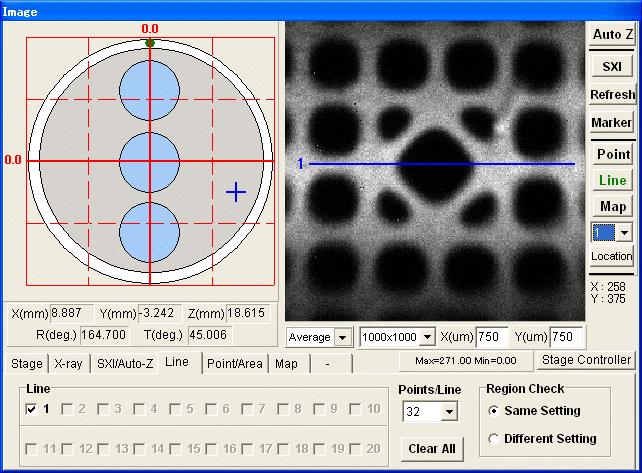
10 Sample Navigation The center of the CCD camera image is aligned to the center of the analysis area and focused at the analyzer focal point. When using the camera to move the stage to a desired analysis area; care should be taken to ensure that the stage is at the correct Z height (approximately 16 to17mm with a 1 flat sample holder). The software joystick may be used to move the stage or coordinates may be entered on the Stage tab (the stage will move to the entered coordinates when Move is clicked). The Auto-Z routine is used to determine the correct Z height for each sample. Clicking the Auto-Z button on the right side of the Image window starts the routine. The automated routine acquires spectra, moves the stage Z axis and acquires another spectrum. Spectra are compared at Z heights higher and lower than the current position. The stage is automatically set to the Z position with the maximum count rate. The recommended X-ray setting for the Auto-Z routine is 100um25W15kV. Clicking the SXI button will acquire a secondary electron image from the scanned X-ray source (text in the SXI button turns green while acquiring an image). During acquisition of a secondary electron image, the text in the SXI button turns green. Analysis points, lines, and maps are defined using the SXI image. Click the SXI button a second time to stop acquiring an image (SXI button text returns to black). The SXI button can not be clicked when a high power X-ray setting is selected. There are three modes for collecting SXI images: Slow, Fast, and Average. Slow and Fast modes display a new image with every frame. Average mode adds frames in a persisted image which is used to enhance image quality. The persisted image will be re-acquired if the Refresh button is clicked. Magnification is chosen by selecting the desired raster size from the drop down menu next to the frame rate window.
 then selecting area.")
11 Analysis areas can be defined on the SXI image by selecting Point (or Area), Line, or Map. When creating an analysis Point or Area, click the point button on the right side of the Image window. An analysis point will be placed in the center of the SXI image. Analysis points can be changed to areas with a right click (on the point) then selecting area. Analysis points or areas can be added by clicking in the SXI image (adds a point where the mouse is clicked) or by clicking Add in the Point/Area tab under Point Center (adds a point in the center of the image). Analysis points and areas can be moved by clicking (holding the mouse button) and dragging them to the desired location, or by right clicking on the point or area and changing the coordinates. Users can define up to 20 points or areas. To define an analysis line, click the Line button on the right side of the Image window. Vertical, Horizontal, and Free Line mode can be chosen by right clicking on the line and selecting the desired option. Selecting the Map button will create a map area on the SXI image. To change the size and position of the area the user may click and drag edges of the box or drag the whole box. A right click on the map area will bring up a sub menu; selecting coordinates will allow the user to directly enter coordinates and window size.
12
13 The SXI/Auto-Z tab on the lower part of the Image window contains the X-ray parameter setting for SXI imaging and Auto-Z tab. The X-ray Setting pull-down list box in the Setting group allows to you to select the predefined X-ray beam setting to use for data collection.

14 Data Acquisition Acquisition Setting Window Region Name: You can enter the Transition Name (e.g. Ag3d5). Other energy region parameters will be set automatically if the region parameters are registered in Element Table described later. Pass Energy (ev): The Pass Energy pull-down list box allows to you to select the energy resolution (Pass Energy) with which to collect data. Lower (ev): The Lower edit box allows to you to set the lower binding energy of energy region. Range (ev): The Range edit box allows to you to set the energy width of the energy region.


15 Energy Step (ev): The Energy Step edit box allows to you to set the energy difference (step) between adjacent data points. Repeats: The Repeats edit box allows to you to set the number of times to accumulate the collecting data. Check Boxes: The check boxes left side of the energy region parameters allows to you to select or deselect the energy region settings. Clicking the Folder button opens a file name and folder setting dialog box that allows you to select the data folder and file name to store the data. (Figure below) Clicking the Acquire button to start to collect the data with established acquisition settings.

16 Starting the Ion Gun Starting the Ion Gun a. In the Watcher vacuum tasks section, select Diff vlv open to start differentially pumping the Ion Gun.


17 b. Choose the ion gun file desired. Set the Ion Gun to Standby. c. Turn the RVG050 power on and set to limit switch to Set point (Extractor Pressure should regulate to ~10mPa in a few minutes).
18 To shut off the Ion Gun, switch the RVG050 to limit and turn the Ion Gun off. The ion gun may be used to do a timed sputtering of the surface by setting the sputter time in minutes I the ion gun menu and clicking the Sputter button. The gun may be used in a depth profile mode by setting the sputter conditions in the acquisition menu In Acquisition Setting window, toggling the Sputter Mode button will expand the window and allow for the sputter conditions setup: Sputter Mode: Options are alternating and continuous. In the alternating mode, data acquisition and sputtering are performed in alternating time intervals. In the continuous mode, data acquisition and sputtering occur simultaneously Sputter Time: Specifies the total time the ion gun will sputter. This does not include the time needed to acquire the data in an alternating sputter profile Interval Time: The length of time the ion gun will sputter between data acquisition cycles. This parameter appears only when the alternating sputter mode is selected. This parameter is only available when the alternating sputter mode is selected Delayed Acq. Time: Specify a delay time, in seconds, after sputtering is completed and before data acquisition is performed. A time delay may be required for some insulating samples in order for all surface potentials to reach a new steady state condition following sputtering. This parameter is only available when the alternating sputter mode is selected. Num (Presputter): Specifies the number of spectral acquisition to be done prior to the first sputter interval. X-Ray while sputtering: Allows the X-ray beam to stay on while sputtering. This option should be left off if there is a risk of sample damage as a result of prolonged X-ray irradiation.
The PHI VersaProbe operates with two essential software programs: PHI Summitt and Vacuum Watcher. A third program, MultiPak, handles data reduction.
 PHI VersaProbe Scanning XPS System I. Overview The PHI VersaProbe operates with two essential software programs: PHI Summitt and Vacuum Watcher. A third program, MultiPak, handles data reduction. PHI Summitt
Kratos AXIS Ultra DLD X-ray Photoelectron Spectrometer Instructions
 Kratos AXIS Ultra DLD X-ray Photoelectron Spectrometer Instructions Note: Enter your complete name, CMRF user code, and date into the record book. You must have previously filled out a project information
680 System Operator s Guide
 680 System Operator s Guide For AES PC-ACCESS, Ver. 7 Part No. 647986 Rev. A Copyright 2000 Physical Electronics, Inc. 6509 Flying Cloud Drive Eden Prairie, MN 55344 The PHI logo is a registered trademark
Technical Procedure for Scanning Electron Microscope/ Energy Dispersive X-Ray System (SEM/EDX) for non-gsr Casework
 for non-gsr Casework") Technical Procedure for Scanning Electron Microscope/ Energy Dispersive X-Ray System (SEM/EDX) for non-gsr Casework 1.0 Purpose This technical procedure shall be followed for the operation of the Scanning
Technical Procedure for Scanning Electron Microscope/ Energy Dispersive X-Ray System (SEM/EDX) for non-gsr Casework 1.0 Purpose This technical procedure shall be followed for the operation of the Scanning
Scanning Electron Microscopy (FEI Versa 3D Dual Beam)
") Scanning Electron Microscopy (FEI Versa 3D Dual Beam) This operating procedure intends to provide guidance for basic measurements on a standard sample with FEI Versa 3D SEM. For more advanced techniques
Scanning Electron Microscopy (FEI Versa 3D Dual Beam) This operating procedure intends to provide guidance for basic measurements on a standard sample with FEI Versa 3D SEM. For more advanced techniques
Operation Procedure for Phillips XL30 ESEM
 Operation Procedure for Phillips XL30 ESEM The ESEM will be left in the ON state when not in use. The chamber will be at high vacuum, filament on, stage at home position, VAC and HT buttons lit, and monitor
Cover Page for Lab Report Group Portion. Boundary Layer Measurements
 Cover Page for Lab Report Group Portion Boundary Layer Measurements Prepared by Professor J. M. Cimbala, Penn State University Latest revision: 23 February 2017 Name 1: Name 2: Name 3: [Name 4: ] Date:
Standard Operating Procedure of nanoir2-s
 Standard Operating Procedure of nanoir2-s The Anasys nanoir2 system is the AFM-based nanoscale infrared (IR) spectrometer, which has a patented technique based on photothermal induced resonance (PTIR),
FIB Operating Procedure. Effective Date: 08/14/2012 Author(s): Jiong Hua Phone:
: Jiong Hua Phone:") FIB Operating Procedure Effective Date: 08/14/2012 Author(s): Jiong Hua Phone: 402-472-3773 Email: jhua2@unl.edu 1 1 Introduction 1.1 Key Words Focused Ion Beam (FIB), FEI Strata 201, Ion milling 1.2 Purpose
FIB Operating Procedure Effective Date: 08/14/2012 Author(s): Jiong Hua Phone: 402-472-3773 Email: jhua2@unl.edu 1 1 Introduction 1.1 Key Words Focused Ion Beam (FIB), FEI Strata 201, Ion milling 1.2 Purpose
1.2 Universiti Teknologi Brunei (UTB) reserves the right to award the tender in part or in full.
 reserves the right to award the tender in part or in full.") TENDER SPECIFICATIONS FOR THE SUPPLY, DELIVERY, INSTALLATION AND COMMISSIONING OF ONE UNIT OF VARIABLE PRESSURE ENVIRONMENTAL SCANNING ELECTRON MICROSCOPE (SEM) CUM ENERGY DISPERSIVE SPECTROSCOPY (EDS)
TENDER SPECIFICATIONS FOR THE SUPPLY, DELIVERY, INSTALLATION AND COMMISSIONING OF ONE UNIT OF VARIABLE PRESSURE ENVIRONMENTAL SCANNING ELECTRON MICROSCOPE (SEM) CUM ENERGY DISPERSIVE SPECTROSCOPY (EDS)
University of Minnesota Nano Fabrication Center Standard Operating Procedure
 Equipment Name: Focused Ion Beam (FIB) Coral Name: fib Revision Number: 2 Model: FEI Quanta 200 3D Revisionist: Kevin Roberts Location: Area 3 Date: 9/17/2013 1 Description The Quanta 200 3D is a DualBeam
Processing data with Mestrelab Mnova
 Processing data with Mestrelab Mnova This exercise has three parts: a 1D 1 H spectrum to baseline correct, integrate, peak-pick, and plot; a 2D spectrum to plot with a 1 H spectrum as a projection; and
SEM- EDS Instruction Manual
 SEM- EDS Instruction Manual Double-click on the Spirit icon ( ) on the desktop to start the software program. I. X-ray Functions Access the basic X-ray acquisition, display and analysis functions through
Standard Operating Procedure II: EDS (Bruker Flat-Quad)
") Standard Operating Procedure II: EDS (Bruker Flat-Quad) ywcmatsci.yale.edu ESC II, Room A119F 810 West Campus Drive West Haven, CT 06516 Version 1.1, October 2018 1 > FOLLOW the SOP strictly to keep the
Standard Operating Procedure II: EDS (Bruker Flat-Quad) ywcmatsci.yale.edu ESC II, Room A119F 810 West Campus Drive West Haven, CT 06516 Version 1.1, October 2018 1 > FOLLOW the SOP strictly to keep the
Quick Start Bruker Dimension Icon AFM
 Do not remove Quick Start Bruker Dimension Icon AFM March 3, 2015 GLA Contacts Harold Fu (hfu@caltech.edu) Weilai Yu (wyyu@caltech.edu) Bruker Tech Support (AFMSupport@bruker-nano.com 800-873-9750) Watch
SPM Training Manual Veeco Bioscope II NIFTI-NUANCE Center Northwestern University
 SPM Training Manual Veeco Bioscope II NIFTI-NUANCE Center Northwestern University Introduction: Scanning Probe Microscopy (SPM) is a general term referring to surface characterization techniques that utilize
2.1. Log on to the TUMI system (you cannot proceed further until this is done).
.") FEI DB235 ex-situ lift out TEM sample preparation procedure Nicholas G Rudawski ngr@ufledu (805) 252-4916 Last updated: 06/19/15 DISCLAIMER: this procedure describes one specific method for preparing ex-situ
FEI DB235 ex-situ lift out TEM sample preparation procedure Nicholas G Rudawski ngr@ufledu (805) 252-4916 Last updated: 06/19/15 DISCLAIMER: this procedure describes one specific method for preparing ex-situ
Dektak Step by Step Instructions:
 Dektak Step by Step Instructions: Before Using the Equipment SIGN IN THE LOG BOOK Part 1: Setup 1. Turn on the switch at the back of the dektak machine. Then start up the computer. 2. Place the sample
Reference. TDS7000 Series Digital Phosphor Oscilloscopes
 Reference TDS7000 Series Digital Phosphor Oscilloscopes 07-070-00 0707000 To Use the Front Panel You can use the dedicated, front-panel knobs and buttons to do the most common operations. Turn INTENSITY
Liquid Chromatography- Mass Spectrometer Manual
 Liquid Chromatography- Mass Spectrometer Manual Joshua Willis, Elizabeth Sattely Department of Chemical Engineering Stanford University November 6, 2014 Abstract This manual will explain the LC/MS, its
CHA EVAPORATOR. User guidelines. p.1. by Carlos Manzanedo. Last revised: 10/05/2000
 CHA EVAPORATOR User guidelines by Carlos Manzanedo. Last revised: 10/05/2000 p.1 Introduction. The CHA evaporator has the following characteristics: 1. 2 independent resistive power supplies. 2. 1 Electron
FEI Strata Dual-beam FIB
 FEI Strata Dual-beam FIB Quick start Guide Compiled by Mat t hew Hughes and Tony Chen Page 0 Purpose of this guide INTRODUCTION This quick start guide is meant to provide cursory operational knowledge
READ THIS FIRST. Morphologi G3. Quick Start Guide. MAN0412 Issue1.1
 READ THIS FIRST Morphologi G3 Quick Start Guide MAN0412 Issue1.1 Malvern Instruments Ltd. 2008 Malvern Instruments makes every effort to ensure that this document is correct. However, due to Malvern Instruments
CHA EVAPORATOR Short Reference User guidelines
 CHA EVAPORATOR Short Reference User guidelines by Carlos Manzanedo. Last revised: 10/05/2000 p.1 Procedure: The CHA evaporator is divided into 16 different panels. These panels are labeled on the machine
XRD-DSC Sample Alignment (BB) Part
 Part") XRD-DSC Sample Alignment (BB) Part Contents Contents 1. How to set Part conditions...1 1.1 Setting conditions... 1 1.2 Customizing scan conditions and slit conditions... 5 2. Sample alignment sequence...9
XRD-DSC Sample Alignment (BB) Part Contents Contents 1. How to set Part conditions...1 1.1 Setting conditions... 1 1.2 Customizing scan conditions and slit conditions... 5 2. Sample alignment sequence...9
Lab Determining the Screen Resolution of a Computer
 Lab 1.3.3 Determining the Screen Resolution of a Computer Objectives Determine the current screen resolution of a PC monitor. Determine the maximum resolution for the highest color quality. Calculate the
DektakXT Profilometer. Standard Operating Procedure
 DektakXT Profilometer Standard Operating Procedure 1. System startup and sample loading: a. Ensure system is powered on by looking at the controller to the left of the computer.(it is an online software,
JEM 2100 Manual. Operation and Basic Alignment Instructions. Check the vacuum levels (power supply closet) Column (blue scale): < 2.
 Column (blue scale): < 2.") 1. Verify the vacuum: JEM 2100 Manual Operation and Basic Alignment Instructions Check the vacuum levels (power supply closet) Column (blue scale): < 2.5x10⁻⁵ Pa If vacuum is not good enough, contact somebody
1. Verify the vacuum: JEM 2100 Manual Operation and Basic Alignment Instructions Check the vacuum levels (power supply closet) Column (blue scale): < 2.5x10⁻⁵ Pa If vacuum is not good enough, contact somebody
E X P E R I M E N T 1
 E X P E R I M E N T 1 Getting to Know Data Studio Produced by the Physics Staff at Collin College Copyright Collin College Physics Department. All Rights Reserved. University Physics, Exp 1: Getting to
Operating Procedures for RECO1 & RECO2
 Operating Procedures for RECO1 & RECO2 Reconstruction of Data 1) Open CT Pro 3D a. Remember, when the computer you are working on is receiving files from the scanner, it cannot reconstruct data b. You
University of Minnesota Minnesota Nano Center Standard Operating Procedure
 Equipment Name: CHA Evaporator Coral Name: ebevap-cha Revision Number: 12 Model: SEC 600 Revisionist: L. von Dissen Location: PAN Bay 3 Date: 04/13/2018 1 Description The CHA Evaporator is a single source
PSC300 Operation Manual
 PSC300 Operation Manual Version 9.10 General information Prior to any attempt to operate this Columbia PSC 300, operator should read and understand the complete operation of the cubing system. It is very
TL-2900 AMMONIA & NITRATE ANALYZER DUAL CHANNEL
 TL-2900 AMMONIA & NITRATE ANALYZER DUAL CHANNEL DATA ACQUISITION SYSTEM V.15.4 INSTRUCTION MANUAL Timberline Instruments, LLC 1880 S. Flatiron Ct., Unit I Boulder, Colorado 80301 Ph: (303) 440-8779 Fx:
1. Check the accelerating voltage, must be at 200 kv (right screen), HT (µa) (left panel) at and Emission (left panel) at
, HT (µa) (left panel) at and Emission (left panel) at") JEOL 2010F MANUAL Quick check list 1. Check the accelerating voltage, must be at 200 kv (right screen), HT (µa) (left panel) at 0.96-0.97 and Emission (left panel) at 155-160. 2. Check the vacuum sequence
JEOL 2010F MANUAL Quick check list 1. Check the accelerating voltage, must be at 200 kv (right screen), HT (µa) (left panel) at 0.96-0.97 and Emission (left panel) at 155-160. 2. Check the vacuum sequence
1.0 ThermoNicolet Nexus 670 FTIR Spectrometer Instructions
 1.0 ThermoNicolet Nexus 670 FTIR Spectrometer Instructions 1.1 Click on the OMNIC icon to open the software. 1.2 Check that a signal is being measured by opening the Experiment Setup menu under the Collect
Printing From Applications: Adobe InDesign CS3, CS4, and CS5
 Printing From Applications: Adobe InDesign CS3, CS4, and CS5 ColorBurst allows you to print directly from InDesign to the ColorBurst Job List. ColorBurst can be added as a network printer, which can then
FEI FIB Focused Ion Beam
 Operating Manual Part 1 FEI FIB Focused Ion Beam IF IN DOUBT, ASK 1.00 IF ANYTHING UNUSUAL HAPPENS, OR IF THERE IS ANYTHING YOU ARE UNSURE ABOUT, STOP AND CONTACT ME! DO NOT PROCEED OR ATTEMPT TO FIX THE
Durham Magneto Optics Ltd. NanoMOKE 3 Wafer Mapper. Specifications
 Durham Magneto Optics Ltd NanoMOKE 3 Wafer Mapper Specifications Overview The NanoMOKE 3 Wafer Mapper is an ultrahigh sensitivity Kerr effect magnetometer specially configured for measuring magnetic hysteresis
University of Minnesota College of Science and Engineering Characterization Facility Ganesha SAXSLAB User manual
 University of Minnesota College of Science and Engineering Characterization Facility Ganesha SAXSLAB User manual # Section Pg # 1 Planning a SAXS experiment 1 2 Initial Setup 2 3 Sample mounting and loading
For the SIA. Applications of Propagation Delay & Skew tool. Introduction. Theory of Operation. Propagation Delay & Skew Tool
 For the SIA Applications of Propagation Delay & Skew tool Determine signal propagation delay time Detect skewing between channels on rising or falling edges Create histograms of different edge relationships
Figure 1. MFP-3D software tray
 Asylum MFP-3D AFM SOP January 2017 Purpose of this Instrument: To obtain 3D surface topography at sub-nanometer scale resolution, measure contact and friction forces between surfaces in contact, measure
using the Scott A Speakman, Ph.D Center for Materials Science and Engineering at MIT
 X-Ray Reflectivity using the PANalytical X Pert Pro MPD Scott A Speakman, Ph.D Center for Materials Science and Engineering at MIT http://prism.mit.edu/xray Modified for configuration used at University
Personal Protective Equipment Wear nitrile gloves, lab coat, and safety glasses as a minimum protection, unless otherwise indicated.
 4pt Bending, Mouse This protocol is for standard Jepsen 4pt bending of adult mouse bone. Safety considerations Please reference the Jepsen laboratory when using this protocol. This protocol is subject
Mini Micro Pulse Lidar System
 Mini Micro Pulse Lidar System MiniMPL-532-C Sensor Suite Operations Manual Version: June 2016 THIS PAGE INTENTIONALLY LEFT BLANK 2 Table of Contents MINIMPL SENSOR SUITE SYSTEM: RECORD OF PURCHASE... 4
Data Collection Using APEX3. March 30, Chemical Crystallography Laboratory
 Data Collection Using APEX3 Page 1 of 10 Data Collection Using APEX3 March 30, 2017 Chemical Crystallography Laboratory Author: Douglas R. Powell Data Collection Using APEX3 Page 2 of 10 Distribution Douglas
EAN-Performance and Latency
 EAN-Performance and Latency PN: EAN-Performance-and-Latency 6/4/2018 SightLine Applications, Inc. Contact: Web: sightlineapplications.com Sales: sales@sightlineapplications.com Support: support@sightlineapplications.com
PulseCounter Neutron & Gamma Spectrometry Software Manual
 PulseCounter Neutron & Gamma Spectrometry Software Manual MAXIMUS ENERGY CORPORATION Written by Dr. Max I. Fomitchev-Zamilov Web: maximus.energy TABLE OF CONTENTS 0. GENERAL INFORMATION 1. DEFAULT SCREEN
The DataView PowerPad III Control Panel
 Setting Up a Recording Session in the DataView PowerPad III Control Panel By Mike Van Dunk The DataView PowerPad III Control Panel is designed for working with AEMC PowerPad III Power Quality Analyzers,
SNR Playback Viewer SNR Version 1.9.7
 User Manual SNR Playback Viewer SNR Version 1.9.7 Modular Network Video Recorder Note: To ensure proper operation, please read this manual thoroughly before using the product and retain the information
D-901 PC SOFTWARE Version 3
 INSTRUCTION MANUAL D-901 PC SOFTWARE Version 3 Please follow the instructions in this manual to obtain the optimum results from this unit. We also recommend that you keep this manual handy for future reference.
MestReNova Manual for Chem 201/202. October, 2015.
 1. Introduction to 1-D NMR Data Processing with MestReNova The MestReNova program can do all of the routine NMR data processing needed for Chem 201 and 202 and will be available through the Reed downloads
CHECKLIST FOR VERIOS OPERATION 1. GENERAL The SEM lab is used assuming "operating room" cleanliness, i.e., the SEM lab is a high visibility lab and
 CHECKLIST FOR VERIOS OPERATION 1. GENERAL The SEM lab is used assuming "operating room" cleanliness, i.e., the SEM lab is a high visibility lab and must be kept clean and neat so clean up behind yourself
ASSEMBLY AND CALIBRATION
 CineMax Kit ASSEMBLY AND CALIBRATION www.cineversum.com Ref: T9003000 Rev: 01 Part. No.: R599766 Changes CineVERSUM provides this manual as is without warranty of any kind, either expressed or implied,
HV/PHA Adjustment (PB) Part
 Part") HV/PHA Adjustment (PB) Part Contents Contents 1. How to set Part conditions...1 1.1 Setting conditions... 1 2. HV/PHA adjustment sequence...7 3. How to use this Part...9 HV/PHA Adjustment (PB) Part i
HV/PHA Adjustment (PB) Part Contents Contents 1. How to set Part conditions...1 1.1 Setting conditions... 1 2. HV/PHA adjustment sequence...7 3. How to use this Part...9 HV/PHA Adjustment (PB) Part i
Solutions to Embedded System Design Challenges Part II
 Solutions to Embedded System Design Challenges Part II Time-Saving Tips to Improve Productivity In Embedded System Design, Validation and Debug Hi, my name is Mike Juliana. Welcome to today s elearning.
PYROPTIX TM IMAGE PROCESSING SOFTWARE
 Innovative Technologies for Maximum Efficiency PYROPTIX TM IMAGE PROCESSING SOFTWARE V1.0 SOFTWARE GUIDE 2017 Enertechnix Inc. PyrOptix Image Processing Software v1.0 Section Index 1. Software Overview...
ivw-fd122 Video Wall Controller MODEL: ivw-fd122 Video Wall Controller Supports 2 x 2 Video Wall Array User Manual Page i Rev. 1.
 MODEL: ivw-fd122 Video Wall Controller Supports 2 x 2 Video Wall Array User Manual Rev. 1.01 Page i Copyright COPYRIGHT NOTICE The information in this document is subject to change without prior notice
iii Table of Contents
 i iii Table of Contents Display Setup Tutorial....................... 1 Launching Catalyst Control Center 1 The Catalyst Control Center Wizard 2 Enabling a second display 3 Enabling A Standard TV 7 Setting
BitWise (V2.1 and later) includes features for determining AP240 settings and measuring the Single Ion Area.
 includes features for determining AP240 settings and measuring the Single Ion Area.") BitWise. Instructions for New Features in ToF-AMS DAQ V2.1 Prepared by Joel Kimmel University of Colorado at Boulder & Aerodyne Research Inc. Last Revised 15-Jun-07 BitWise (V2.1 and later) includes features
BitWise. Instructions for New Features in ToF-AMS DAQ V2.1 Prepared by Joel Kimmel University of Colorado at Boulder & Aerodyne Research Inc. Last Revised 15-Jun-07 BitWise (V2.1 and later) includes features
Approved by: / / R. Battaglia 12/16/2016
 Fabrication Laboratory Revision: H Rev Date: 12/16/16 Approved by: Process Engineer / / R. Battaglia 12/16/2016 Equipment Engineer 1 SCOPE The purpose of this document is to detail the use of the Varian
Standard Operating Procedure for FEI Helios 660 NanoLab Part I: SEM Version
 Standard Operating Procedure for FEI Helios 660 NanoLab Part I: SEM Version Helios reservations may be made online using the NERCF website. Note: Always wear gloves when venting the system and exchanging
Table of content. Table of content Introduction Concepts Hardware setup...4
 Table of content Table of content... 1 Introduction... 2 1. Concepts...3 2. Hardware setup...4 2.1. ArtNet, Nodes and Switches...4 2.2. e:cue butlers...5 2.3. Computer...5 3. Installation...6 4. LED Mapper
F7000NV ROBOT VISION OPERATING MANUAL
 Rev. C Feb 2012 F7000NV ROBOT VISION OPERATING MANUAL Rev. C Feb 2012 This page has intentionally been left blank. Contents Contents Chapter 1. Getting Started... 5 1. Preface... 5 2. Manuals... 5 3. Setting
Preparing for remote data collection at NE-CAT
 Preparing for remote data collection at NE-CAT Important Note: The beamtime and remote login privileges are intended just for you and your group. You are not allowed to share these with any other person
Quick Start Guide. Multidimensional Imaging
 Quick Start Guide Multidimensional Imaging Printed 11/2012 Multidimensional Imaging Content Quick Start Guide Content 1 Introduction 4 2 Set up multi-channel experiments 5 2.1 Set up a new experiment
Statement SmartLCT User s Manual Welcome to use the product from Xi an NovaStar Tech Co., Ltd. (hereinafter referred to as NovaStar ). It is our great
. It is our great") LED Display Configuration Software SmartLCT User s Manual Software Version: V3.0 Rev3.0.0 NS110100239 Statement SmartLCT User s Manual Welcome to use the product from Xi an NovaStar Tech Co., Ltd. (hereinafter
LED Display Configuration Software SmartLCT User s Manual Software Version: V3.0 Rev3.0.0 NS110100239 Statement SmartLCT User s Manual Welcome to use the product from Xi an NovaStar Tech Co., Ltd. (hereinafter
SNG-2150C User s Guide
 SNG-2150C User s Guide Avcom of Virginia SNG-2150C User s Guide 7730 Whitepine Road Revision 001 Richmond, VA 23237 USA GENERAL SAFETY If one or more components of your earth station are connected to 120
Gazer VI700A-SYNC2 and VI700W- SYNC2 INSTALLATION MANUAL
 Gazer VI700A-SYNC2 and VI700W- SYNC2 INSTALLATION MANUAL Contents List of compatible cars... 3 Package contents... 4 Special information... 6 Car interior disassembly and connection guide for Ford Focus...
IMSERC NMR MANUAL 05: Manual Operation of Agilent NMR Spectrometers (Chem350 Interface)
") IMSERC NMR MANUAL 05: Manual Operation of Agilent NMR Spectrometers (Chem350 Interface) Last updated: October 12, 2011 by Josh Kurutz THIS PAGE = QUICK START GUIDE 0) At the computer, make sure VNMRJ is
IMSERC NMR MANUAL 05: Manual Operation of Agilent NMR Spectrometers (Chem350 Interface) Last updated: October 12, 2011 by Josh Kurutz THIS PAGE = QUICK START GUIDE 0) At the computer, make sure VNMRJ is
2-/4-Channel Cam Viewer E- series for Automatic License Plate Recognition CV7-LP
 2-/4-Channel Cam Viewer E- series for Automatic License Plate Recognition Copyright 2-/4-Channel Cam Viewer E-series for Automatic License Plate Recognition Copyright 2018 by PLANET Technology Corp. All
K Service Source. Apple High-Res Monochrome Monitor
 K Service Source Apple High-Res Monochrome Monitor K Service Source Specifications Apple High-Resolution Monochrome Monitor Specifications Characteristics - 1 Characteristics Picture Tube 12-in. diagonal
How to Optimize Ad-Detective
 How to Optimize Ad-Detective Ad-Detective technology is based upon black level detection. There are several important criteria to consider: 1. Does the video have black frames to detect? Are there any
LUMIGEN INSTRUMENT CENTER X-RAY CRYSTALLOGRAPHIC LABORATORY: WAYNE STATE UNIVERSITY
 Standard Operating Procedure for the Bruker X8 APEX II Single-Crystal X- Ray Diffractometer Contact Manager: Dr. Cassie Ward ward@wayne.edu Office room 061 Chemistry (313) 577-2587 LIC Lab: (313) 577-0518
Florida State University Thayumanasamy Somasundaram
 2016 Florida State University 2013-16 Thayumanasamy Somasundaram [PANALYTICAL X-PERT PRO POWDER DATA COLLECTION] A quick start-up procedure for collecting powder x-ray diffraction data from PANalytical
Fully ly Automaticti. Motorised Satellite t TV System. User s manual REV
 REV. 1.0 Fully ly Automaticti Motorised Satellite t TV System User s manual Customer Help Line: 1300 139 255 Support Email: support@satkingpromax.com.au Website: www.satkingpromax.com.au www.satkingpromax.com.au
CARESTREAM VITA/VITA LE/VITA SE CR System Long Length Imaging User Guide
 CARESTREAM VITA/VITA LE/VITA SE CR System Long Length Imaging User Guide Use of the Guide Carestream CR Systems are designed to meet international safety and performance standards. Personnel operating
TechNote: MuraTool CA: 1 2/9/00. Figure 1: High contrast fringe ring mura on a microdisplay
 Mura: The Japanese word for blemish has been widely adopted by the display industry to describe almost all irregular luminosity variation defects in liquid crystal displays. Mura defects are caused by
TT AFM LongBeach Procedures and Protocols V2.1
 TT AFM LongBeach Procedures and Protocols V2.1 1. Startup Procedure 1. Turn on PC: Allow to boot to Windows. Turn on monitor. Password is afm 2. Turn on second PC that controls the video camera. 3. Turn
ExtIO Plugin User Guide
 Overview The SDRplay Radio combines together the Mirics flexible tuner front-end and USB Bridge to produce a SDR platform capable of being used for a wide range of worldwide radio and TV standards. This
Neutron Spectrometer Operation Manual
 Neutron Spectrometer Operation Manual MIT Department of Physics (Dated: October 16, 2014) This document is for assisting in the understanding and accessing of the technical aspects of the neutron physics
2013, 2014 Hewlett-Packard Development Company, L.P.
 User Guide 2013, 2014 Hewlett-Packard Development Company, L.P. The only warranties for HP products and services are set forth in the express warranty statements accompanying such products and services.
Waters GCT GCMS Training Manual (Nominal Mass GCMS version) 02/06/2012 S.V.
 02/06/2012 S.V.") 1234 Hach Hall 515-294-5805 www.cif.iastate.edu Waters GCT GCMS Training Manual (Nominal Mass GCMS version) 02/06/2012 S.V. Location: Contact: 1238 Hach Hall Steve Veysey, 1234 Hach Hall; Kamel Harrata,
1234 Hach Hall 515-294-5805 www.cif.iastate.edu Waters GCT GCMS Training Manual (Nominal Mass GCMS version) 02/06/2012 S.V. Location: Contact: 1238 Hach Hall Steve Veysey, 1234 Hach Hall; Kamel Harrata,
PHY221 Lab 1 Discovering Motion: Introduction to Logger Pro and the Motion Detector; Motion with Constant Velocity
 PHY221 Lab 1 Discovering Motion: Introduction to Logger Pro and the Motion Detector; Motion with Constant Velocity Print Your Name Print Your Partners' Names Instructions August 31, 2016 Before lab, read
AFM1 Imaging Operation Procedure (Tapping Mode or Contact Mode)
") AFM1 Imaging Operation Procedure (Tapping Mode or Contact Mode) 1. Log into the Log Usage system on the SMIF web site 2. Open Nanoscope 6.14r1 software by double clicking on the Nanoscope 6.14r1 desktop
AFM1 Imaging Operation Procedure (Tapping Mode or Contact Mode) 1. Log into the Log Usage system on the SMIF web site 2. Open Nanoscope 6.14r1 software by double clicking on the Nanoscope 6.14r1 desktop
ivw-fd133 Video Wall Controller MODEL: ivw-fd133 Video Wall Controller Supports 3 x 3 and 2 x 2 Video Wall Array User Manual Page i Rev. 1.
 MODEL: ivw-fd133 Video Wall Controller Supports 3 x 3 and 2 x 2 Video Wall Array User Manual Rev. 1.01 Page i Copyright COPYRIGHT NOTICE The information in this document is subject to change without prior
Linkage 3.6. User s Guide
 Linkage 3.6 User s Guide David Rector Friday, December 01, 2017 Table of Contents Table of Contents... 2 Release Notes (Recently New and Changed Stuff)... 3 Installation... 3 Running the Linkage Program...
PCIe: EYE DIAGRAM ANALYSIS IN HYPERLYNX
 PCIe: EYE DIAGRAM ANALYSIS IN HYPERLYNX w w w. m e n t o r. c o m PCIe: Eye Diagram Analysis in HyperLynx PCI Express Tutorial This PCI Express tutorial will walk you through time-domain eye diagram analysis
Dell D3218HN. User s Guide. Regulatory model: D3218HNo
 Dell D3218HN User s Guide Regulatory model: D3218HNo Notes, cautions, and warnings NOTE: A NOTE indicates important information that helps you make better use of your computer. CAUTION: A CAUTION indicates
Import and quantification of a micro titer plate image
 BioNumerics Tutorial: Import and quantification of a micro titer plate image 1 Aims BioNumerics can import character type data from TIFF images. This happens by quantification of the color intensity and/or
ConeXus User Guide. HHAeXchange s Communication Functionality
 HHAeXchange ConeXus User Guide HHAeXchange s Communication Functionality Copyright 2017 Homecare Software Solutions, LLC One Court Square 44th Floor Long Island City, NY 11101 Phone: (718) 407-4633 Fax:
Vasudevan Agilent 1100 Series HPLC w/ DAD & FLD Detector (nonbuffer
 Vasudevan Agilent 1100 Series HPLC w/ DAD & FLD Detector (nonbuffer solvents) Updated November 14, 2017 Instrument instructions can be found at: http://academic.bowdoin.edu/chemistry/resources/instructions.shtml
Veeco Dektak 6M Profilometer
 Veeco Dektak 6M Profilometer System Ranges/Resolutions Range (Å) Resolution (Å) 50 (5nm) to 65K 1 0.5K to 655K 10 2K to 2620K 40 8K to 10000K (1mm) 160 Maximum sample thickness: 31.75mm Scan range: 50
K Service Source. Apple High-Res Monochrome Monitor
 K Service Source Apple High-Res Monochrome Monitor K Service Source Specifications Apple High-Resolution Monochrome Monitor Specifications Characteristics - 1 Characteristics Picture Tube 12-in. diagonal
Getting Started Guide for the V Series
 product pic here Getting Started Guide for the V Series Version 8.7 July 2007 Edition 3725-24476-002/A Trademark Information Polycom and the Polycom logo design are registered trademarks of Polycom, Inc.,
rekordbox TM LIGHTING mode Operation Guide
 rekordbox TM LIGHTING mode Operation Guide Contents 1 Before Start... 3 1.1 Before getting started... 3 1.2 System requirements... 3 1.3 Overview of LIGHTING mode... 4 2 Terms... 6 3 Steps to easily control
User Manual OVP Raman
 Version 6 User Manual OVP Raman 2006 BRUKER OPTIK GmbH, Rudolf-Plank-Straße 27, D-76275 Ettlingen, www.brukeroptics.com All rights reserved. No part of this manual may be reproduced or transmitted in any
Gazer VI700A-SYNC/IN and VI700W- SYNC/IN INSTALLATION MANUAL
 Gazer VI700A-SYNC/IN and VI700W- SYNC/IN INSTALLATION MANUAL Contents List of compatible cars... 3 Package contents... 4 Special information... 6 Car interior disassembly and connection guide for Ford
rekordbox TM LIGHTING mode Operation Guide
 rekordbox TM LIGHTING mode Operation Guide Contents 1 Before Start... 3 1.1 Before getting started... 3 1.2 System requirements... 3 1.3 Overview of LIGHTING mode... 4 2 Terms... 6 3 Steps to easily control
HRXRD Analysis of Epitaxial Thin Films
 HRXRD Analysis of Epitaxial Thin Films on the Rigaku Smartlab Multipurpose Diffractometer Scott A Speakman, Ph.D Center for Materials Science and Engineering at MIT For assistance in the X-ray lab, contact
CytoFLEX Flow Cytometer Quick Start Guide
 Sheath Waste CLASS 1 LASER PRODUCT COMPLIES WITH 21 CFR 1040.10 AND 1040.11 EXCEPT FOR DEVIATIONS PURSUANT TO LASER NOTICE NO. 50 DATED JUNE 24, 2007 MANUFACTURED Sheath B49008AC February 2015 CytoFLEX