OL GS7000 GainMaker Scalable 4-Port Node Installation and Operation Guide
|
|
|
- Francis Conley
- 6 years ago
- Views:
Transcription
1 OL GS7000 GainMaker Scalable 4-Port Node Installation and Operation Guide
2
3 For Your Safety Explanation of Warning and Caution Icons Avoid personal injury and product damage! Do not proceed beyond any symbol until you fully understand the indicated conditions. The following warning and caution icons alert you to important information about the safe operation of this product: You may find this symbol in the document that accompanies this product. This symbol indicates important operating or maintenance instructions. You may find this symbol affixed to the product. This symbol indicates a live terminal where a dangerous voltage may be present; the tip of the flash points to the terminal device. You may find this symbol affixed to the product. This symbol indicates a protective ground terminal. You may find this symbol affixed to the product. This symbol indicates a chassis terminal (normally used for equipotential bonding). You may find this symbol affixed to the product. This symbol warns of a potentially hot surface. You may find this symbol affixed to the product and in this document. This symbol indicates an infrared laser that transmits intensity-modulated light and emits invisible laser radiation or an LED that transmits intensity-modulated light. Important Please read this entire guide. If this guide provides installation or operation instructions, give particular attention to all safety statements included in this guide.
4 Notices Trademark Acknowledgments Cisco and the Cisco logo are trademarks or registered trademarks of Cisco and/or its affiliates in the U.S. and other countries. To view a list of Cisco trademarks, go to this URL: Third party trademarks mentioned are the property of their respective owners. The use of the word partner does not imply a partnership relationship between Cisco and any other company. (1110R) Publication Disclaimer Cisco Systems, Inc. assumes no responsibility for errors or omissions that may appear in this publication. We reserve the right to change this publication at any time without notice. This document is not to be construed as conferring by implication, estoppel, or otherwise any license or right under any copyright or patent, whether or not the use of any information in this document employs an invention claimed in any existing or later issued patent. Copyright 2014 Cisco and/or its affiliates. All rights reserved. Printed in the United States of America. Information in this publication is subject to change without notice. No part of this publication may be reproduced or transmitted in any form, by photocopy, microfilm, xerography, or any other means, or incorporated into any information retrieval system, electronic or mechanical, for any purpose, without the express permission of Cisco Systems, Inc.
5 Contents For Your Safety... 3 Notices... 4 Important Safety Instructions... vii Laser Safety... xv Laser Warning Labels... xvii General Information 1 Equipment Description... 2 Theory of Operation 19 System Diagrams Forward Path Reverse Path Power Distribution RF Amplifier Module Forward Configuration Module Reverse Configuration Module Optical Interface Board (OIB) Optical Receiver Module Optical Transmitter Modules Optical Amplifier (EDFA) Modules Optical Switch Module Status Monitor/Local Control Module Power Supply Module Installation 73 Tools and Test Equipment Node Housing Ports Strand Mounting the Node Pedestal or Wall Mounting the Node Fiber Optic Cable Installation RF Cable Installation Applying Power to the Node Setup and Operation 95 Tools and Test Equipment System Diagrams Forward Path Setup Procedure Reverse Path Setup Procedure OL iii
6 Contents Reconfiguring Forward Signal Routing Reconfiguring Reverse Signal Routing Maintenance 135 Opening and Closing the Housing Preventative Maintenance Removing and Replacing Modules Care and Cleaning of Optical Connectors Troubleshooting 153 No RF Output: Optical Power LED on Receiver Module is off No RF Output: Fiber Optic Light Level is Good, Receiver Optical Power LED is on 156 Poor C/N Performance Poor Distortion Performance Poor Frequency Response No RF Output from Reverse Receiver Customer Support Information 165 Appendix A Technical Information 167 Linear Tilt Chart Forward Equalizer Chart GS7000 Node Accessory Part Numbers Appendix B bdr Digital Reverse Multiplexing Applications 173 Digital Reverse System Overview Digital Reverse Transmitter Module Installation Transmitter Module Setup Procedure Reverse Balancing the Node with Digital Reverse Modules Troubleshooting Appendix C Enhanced Digital Return Multiplexing Applications 191 Enhanced Digital Return System Overview Enhanced Digital Return (EDR) System Installation Transmitter Module Setup Procedure Reverse Balancing the Node with EDR Troubleshooting Appendix D Expanded Fiber Tray 231 iv OL
7 Contents Expanded Fiber Tray Overview Expanded Fiber Tray Installation Fiber Management System Configuration Examples Glossary 245 Index 255 OL v
8
9 Important Safety Instructions Important Safety Instructions Read and Retain Instructions Carefully read all safety and operating instructions before operating this equipment, and retain them for future reference. Follow Instructions and Heed Warnings Follow all operating and use instructions. Pay attention to all warnings and cautions in the operating instructions, as well as those that are affixed to this equipment. Terminology The terms defined below are used in this document. The definitions given are based on those found in safety standards. Service Personnel - The term service personnel applies to trained and qualified individuals who are allowed to install, replace, or service electrical equipment. The service personnel are expected to use their experience and technical skills to avoid possible injury to themselves and others due to hazards that exist in service and restricted access areas. User and Operator - The terms user and operator apply to persons other than service personnel. Ground(ing) and Earth(ing) - The terms ground(ing) and earth(ing) are synonymous. This document uses ground(ing) for clarity, but it can be interpreted as having the same meaning as earth(ing). Electric Shock Hazard This equipment meets applicable safety standards. WARNING: To reduce risk of electric shock, perform only the instructions that are included in the operating instructions. Refer all servicing to qualified service personnel only. Electric shock can cause personal injury or even death. Avoid direct contact with dangerous voltages at all times. Know the following safety warnings and guidelines: Only qualified service personnel are allowed to perform equipment installation or replacement. Only qualified service personnel are allowed to remove chassis covers and access OL vii
10 Important Safety Instructions any of the components inside the chassis. Equipment Placement WARNING: Avoid personal injury and damage to this equipment. An unstable mounting surface may cause this equipment to fall. To protect against equipment damage or injury to personnel, comply with the following: Install this equipment in a restricted access location (access restricted to service personnel). Make sure the mounting surface or rack is stable and can support the size and weight of this equipment. Strand (Aerial) Installation CAUTION: Be aware of the size and weight of strand-mounted equipment during the installation operation. Ensure that the strand can safely support the equipment s weight. Pedestal, Service Closet, Equipment Room or Underground Vault Installation WARNING: Avoid the possibility of personal injury. Ensure proper handling/lifting techniques are employed when working in confined spaces with heavy equipment. Ensure this equipment is securely fastened to the mounting surface or rack where necessary to protect against damage due to any disturbance and subsequent fall. Ensure the mounting surface or rack is appropriately anchored according to manufacturer s specifications. Ensure the installation site meets the ventilation requirements given in the equipment s data sheet to avoid the possibility of equipment overheating. Ensure the installation site and operating environment is compatible with the equipment s International Protection (IP) rating specified in the equipment s data sheet. viii OL
11 Important Safety Instructions Connecting to Utility AC Power Important: If this equipment is a Class I equipment, it must be grounded. If this equipment plugs into an outlet, the outlet must be near this equipment, and must be easily accessible. Connect this equipment only to the power sources that are identified on the equipment-rating label, which is normally located close to the power inlet connector(s). This equipment may have two power sources. Be sure to disconnect all power sources before working on this equipment. If this equipment does not have a main power switch, the power cord connector serves as the disconnect device. Always pull on the plug or the connector to disconnect a cable. Never pull on the cable itself. Connection to Network Power Sources Refer to this equipment s specific installation instructions in this manual or in companion manuals in this series for connection to network ferro-resonant AC power sources. AC Power Shunts AC power shunts may be provided with this equipment. Important: The power shunts (where provided) must be removed before installing modules into a powered housing. With the shunts removed, power surge to the components and RF-connectors is reduced. CAUTION: RF connectors and housing seizure assemblies can be damaged if shunts are not removed from the equipment before installing or removing modules from the housing. Grounding (Utility AC Powered Equipment in Pedestals, Service Closets, etc.) This section provides instructions for verifying that the equipment is properly grounded. Safety Plugs (USA Only) This equipment may be equipped with either a 3-terminal (grounding-type) safety plug or a 2-terminal (polarized) safety plug. The wide blade or the third terminal is provided for safety. Do not defeat the safety purpose of the grounding-type or polarized safety plug. OL ix
12 Important Safety Instructions To properly ground this equipment, follow these safety guidelines: Grounding-Type Plug - For a 3-terminal plug (one terminal on this plug is a protective grounding pin), insert the plug into a grounded mains, 3-terminal outlet. Note: This plug fits only one way. If this plug cannot be fully inserted into the outlet, contact an electrician to replace the obsolete 3-terminal outlet. Polarized Plug - For a 2-terminal plug (a polarized plug with one wide blade and one narrow blade), insert the plug into a polarized mains, 2-terminal outlet in which one socket is wider than the other. Note: If this plug cannot be fully inserted into the outlet, try reversing the plug. If the plug still fails to fit, contact an electrician to replace the obsolete 2-terminal outlet. Grounding Terminal If this equipment is equipped with an external grounding terminal, attach one end of an 18-gauge wire (or larger) to the grounding terminal; then, attach the other end of the wire to a ground, such as a grounded equipment rack. Safety Plugs (European Union) Class I Mains Powered Equipment Provided with a 3-terminal AC inlet and requires connection to a 3-terminal mains supply outlet via a 3-terminal power cord for proper connection to the protective ground. Note: The equipotential bonding terminal provided on some equipment is not designed to function as a protective ground connection. Class II Mains Powered Equipment Provided with a 2-terminal AC inlet that may be connected by a 2-terminal power cord to the mains supply outlet. No connection to the protective ground is required as this class of equipment is provided with double or reinforced and/or supplementary insulation in addition to the basic insulation provided in Class I equipment. Note: Class II equipment, which is subject to EN , is provided with a chassis mounted equipotential bonding terminal. See the section titled Equipotential Bonding for connection instructions. Equipotential Bonding If this equipment is equipped with an external chassis terminal marked with the IEC chassis icon ( ), the installer should refer to CENELEC standard EN or IEC standard IEC for correct equipotential bonding connection instructions. x OL
13 Important Safety Instructions General Servicing Precautions WARNING: Avoid electric shock! Opening or removing this equipment s cover may expose you to dangerous voltages. CAUTION: These servicing precautions are for the guidance of qualified service personnel only. To reduce the risk of electric shock, do not perform any servicing other than that contained in the operating instructions unless you are qualified to do so. Refer all servicing to qualified service personnel. Be aware of the following general precautions and guidelines: Servicing - Servicing is required when this equipment has been damaged in any way, such as power supply cord or plug is damaged, liquid has been spilled or objects have fallen into this equipment, this equipment has been exposed to rain or moisture, does not operate normally, or has been dropped. Wristwatch and Jewelry - For personal safety and to avoid damage of this equipment during service and repair, do not wear electrically conducting objects such as a wristwatch or jewelry. Lightning - Do not work on this equipment, or connect or disconnect cables, during periods of lightning. Labels - Do not remove any warning labels. Replace damaged or illegible warning labels with new ones. Covers - Do not open the cover of this equipment and attempt service unless instructed to do so in the instructions. Refer all servicing to qualified service personnel only. Moisture - Do not allow moisture to enter this equipment. Cleaning - Use a damp cloth for cleaning. Safety Checks - After service, assemble this equipment and perform safety checks to ensure it is safe to use before putting it back into operation. Electrostatic Discharge Electrostatic discharge (ESD) results from the static electricity buildup on the human body and other objects. This static discharge can degrade components and cause failures. Take the following precautions against electrostatic discharge: Use an anti-static bench mat and a wrist strap or ankle strap designed to safely ground ESD potentials through a resistive element. Keep components in their anti-static packaging until installed. OL xi
14 Important Safety Instructions Avoid touching electronic components when installing a module. Fuse Replacement To replace a fuse, comply with the following: Disconnect the power before changing fuses. Identify and clear the condition that caused the original fuse failure. Always use a fuse of the correct type and rating. The correct type and rating are indicated on this equipment. Batteries This product may contain batteries. Special instructions apply regarding the safe use and disposal of batteries: Safety Insert batteries correctly. There may be a risk of explosion if the batteries are incorrectly inserted. Do not attempt to recharge disposable or non-reusable batteries. Please follow instructions provided for charging rechargeable batteries. Replace batteries with the same or equivalent type recommended by manufacturer. Do not expose batteries to temperatures above 100 C (212 F). Disposal The batteries may contain substances that could be harmful to the environment Recycle or dispose of batteries in accordance with the battery manufacturer s instructions and local/national disposal and recycling regulations. The batteries may contain perchlorate, a known hazardous substance, so special handling and disposal of this product might be necessary. For more information about perchlorate and best management practices for perchlorate-containing substance, see Modifications This equipment has been designed and tested to comply with applicable safety, laser safety, and EMC regulations, codes, and standards to ensure safe operation in its intended environment. Refer to this equipment's data sheet for details about regulatory compliance approvals. xii OL
15 Important Safety Instructions Do not make modifications to this equipment. Any changes or modifications could void the user s authority to operate this equipment. Modifications have the potential to degrade the level of protection built into this equipment, putting people and property at risk of injury or damage. Those persons making any modifications expose themselves to the penalties arising from proven non-compliance with regulatory requirements and to civil litigation for compensation in respect of consequential damages or injury. Accessories Use only attachments or accessories specified by the manufacturer. Electromagnetic Compatibility Regulatory Requirements This equipment meets applicable electromagnetic compatibility (EMC) regulatory requirements. Refer to this equipment's data sheet for details about regulatory compliance approvals. EMC performance is dependent upon the use of correctly shielded cables of good quality for all external connections, except the power source, when installing this equipment. Ensure compliance with cable/connector specifications and associated installation instructions where given elsewhere in this manual. EMC Compliance Statements Where this equipment is subject to USA FCC and/or Industry Canada rules, the following statements apply: FCC Statement for Class A Equipment This equipment has been tested and found to comply with the limits for a Class A digital device, pursuant to Part 15 of the FCC Rules. These limits are designed to provide reasonable protection against harmful interference when this equipment is operated in a commercial environment. This equipment generates, uses, and can radiate radio frequency energy and, if not installed and used in accordance with the instruction manual, may cause harmful interference to radio communications. Operation of this equipment in a residential area is likely to cause harmful interference in which case users will be required to correct the interference at their own expense. Industry Canada - Industrie Canadiene Statement This apparatus complies with Canadian ICES-003. Cet appareil est confome à la norme NMB-003 du Canada. CENELEC/CISPR Statement with Respect to Class A Information Technology Equipment This is a Class A equipment. In a domestic environment this equipment may cause OL xiii
16 Important Safety Instructions radio interference in which case the user may be required to take adequate measures. xiv OL
17 Laser Safety Laser Safety Introduction This equipment contains an infrared laser that transmits intensity-modulated light and emits invisible radiation. Warning: Radiation WARNING: Avoid personal injury! Use of controls, adjustments, or procedures other than those specified herein may result in hazardous radiation exposure. Avoid personal injury! The laser light source on this equipment (if a transmitter) or the fiber cables connected to this equipment emit invisible laser radiation. Avoid direct exposure to the laser light source. Avoid personal injury! Viewing the laser output (if a transmitter) or fiber cable with optical instruments (such as eye loupes, magnifiers, or microscopes) may pose an eye hazard. Do not apply power to this equipment if the fiber is unmated or unterminated. Do not stare into an unmated fiber or at any mirror-like surface that could reflect light emitted from an unterminated fiber. Do not view an activated fiber with optical instruments (e.g., eye loupes, magnifiers, microscopes). Use safety-approved optical fiber cable to maintain compliance with applicable laser safety requirements. Warning: Fiber Optic Cables WARNING: Avoid personal injury! Qualified service personnel may only perform the procedures in this manual. Wear safety glasses and use extreme caution when handling fiber optic cables, particularly during splicing or terminating operations. The thin glass fiber core at the center of the cable is fragile when exposed by the removal of cladding and buffer material. It easily fragments into glass splinters. Using tweezers, place splinters immediately in a sealed waste container and dispose of them safely in accordance with local regulations. OL xv
18 Laser Safety Safe Operation for Software Controlling Optical Transmission Equipment If this manual discusses software, the software described is used to monitor and/or control ours and other vendors electrical and optical equipment designed to transmit video, voice, or data signals. Certain safety precautions must be observed when operating equipment of this nature. For equipment specific safety requirements, refer to the appropriate section of the equipment documentation. For safe operation of this software, refer to the following warnings. WARNING: Ensure that all optical connections are complete or terminated before using this equipment to remotely control a laser device. An optical or laser device can pose a hazard to remotely located personnel when operated without their knowledge. Allow only personnel trained in laser safety to operate this software. Otherwise, injuries to personnel may occur. Restrict access of this software to authorized personnel only. Install this software in equipment that is located in a restricted access area. xvi OL


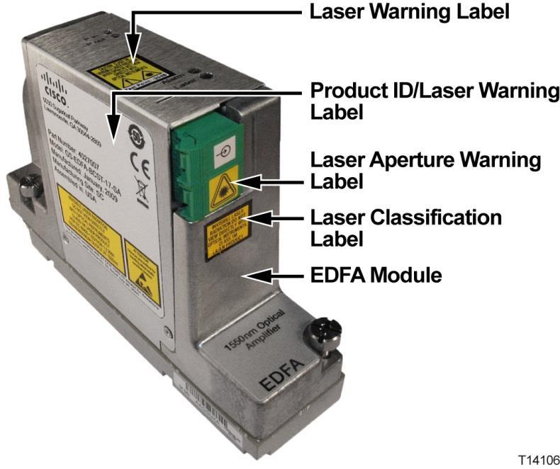
19 Laser Warning Labels Laser Warning Labels Maximum Laser Power The maximum laser power that can be expected from the EDFA optical amplifier for various amplifier configurations is defined in the following table. Output Power Maximum Output CDRH Classification IEC Classification 17 dbm 17 dbm 1 1M 1M 20 dbm 20 dbm 1 1M 1M 22 dbm 22 dbm 1 1M 3B IEC Hazard Level Warning Labels One or more of the labels shown below are located on this product. OL xvii


20 Laser Warning Labels Location of Labels on Equipment The following illustrations display the location of warning labels on this equipment. xviii OL

21 Laser Warning Labels OL xix
22
23 1 Chapter 1 General Information Introduction This manual describes the installation and operation of the GS7000 GainMaker Scalable 4-Port Node. In This Chapter Equipment Description... 2 OL
24 Chapter 1 General Information Equipment Description Overview This section contains a physical and functional description of the GS7000 Node. Physical Description The GS7000 Node is the latest generation 1 GHz optical node platform which uses a completely new housing designed for optimal heat dissipation. The housing has a hinged lid to allow access to the internal electrical and optical components. The housing also has provisions for strand, pedestal, or wall mounting. The base of the housing contains: an RF amplifier module AC power routing forward and reverse configuration modules (configuration will vary) The lid of the housing contains: a fiber management tray and track (included in all nodes) optical receiver and transmitter modules (configuration will vary) EDFA (erbium-doped fiber amplifier) modules and optical switch modules (for hub node application) power supplies (one or two) a status monitor/local control module (optional) Not every GS7000 Node will contain all of these modules. The GS7000 Node is a versatile node that can be configured to meet network requirements. The following illustration shows the external housing of the GS7000 Node. 2 OL

25 Equipment Description The following illustration shows the GS7000 Node internal modules and components. This model is the 4-way forward segmentable node. The 2-way forward segmentable node has a different RF amplifier module. OL

26 Chapter 1 General Information Functional Description Node The GS7000 Node is used in broadband hybrid fiber/coax (HFC) networks. It is configured with the receivers, transmitters, configuration modules, and other modules to meet your unique network requirements. This platform allows independent segmentation and redundancy for both the forward and reverse paths in a reliable, cost-effective package. The GS7000 Node receives forward optical inputs, converts the input to an electrical radio frequency (RF) signal, and outputs the RF signals at up to six ports. The forward bandwidth is from 52 MHz (or 54, or 70, or 86 MHz) to 1002 MHz. The lower edge of the passband is determined by the diplex filter and the reverse amplifier assembly. Diplex filter choices are 52 MHz, 54 MHz, 70 MHz, 86 MHz or 105 MHz. 4 OL
27 Equipment Description The forward path of the GS7000 Node can be deployed with a broadcast 1310/1550 nm optical receiver with common services distributed to either four output ports (all high level) or six output ports (two high level and four lower level). The forward path can also be segmented by using one optical receiver that feeds all output ports, two independent optical receivers that each feed half of the node s output ports (left/right segmentation) or four independent optical receivers that feed four independent forward paths. Forward optical path redundancy is supported via the use of optional local control module. The type of forward segmentation and/or redundancy is determined by the type of RF amplifier assembly and Forward Configuration Module installed in the node. The GS7000 Node s reverse path is equally flexible. Reverse traffic can be segmented or combined and routed to up to four FP or DFB reverse optical transmitters, or to two advanced Baseband Digital Reverse optical transmitters as part of our bdr system. Redundant (back-up) transmitters may be utilized. In addition, an auxiliary input path is provided for reverse signal injection (5-210 MHz). Reverse segmentation and/or redundancy are determined by the type of Reverse Configuration Module installed in the node. The GS7000 Node accepts Optical Transmitter Modules based on the existing 694x/GainMaker optical transmitters. Reverse optical transmitters can be installed to transmit data, video, or both. Reverse bandwidth is determined by the diplex filter and the reverse amplifier assembly. Diplex filter choices are 40 MHz, 42 MHz, 55 MHz, 65 MHz or 85 MHz. The GS7000 Node utilizes new transmitter and receiver module covers that have been designed to allow fiber pigtails storage within them, providing improved fiber management within the node. Up to four optical receivers and up to four analog or two digital transmitters can be installed in the GS7000 Node V AC input power is converted to +24.5, +8.5, -6.0, and +5.5 V DC by an internal power supply to power the GS7000 Node. Hub Node The GS7000 Hub Node performs the same functions as the GS7000 Node with the added benefit of also providing optical gain and optical switching capability. The hub node allows you to push fiber deeper into your network while taking advantage of the RF plant that is already in place. The GS7000 Node can be upgraded to a GS7000 Hub Node in the field. This is accomplished by the installation of optical amplification (EDFA) modules, optical switching modules, and the Status Monitor/Local Control Module in the node lid. The GS7000 Hub Node can then serve as a traditional node feeding the local HFC plant and as an optical hub with the optical amplifiers. The node hub with the amplifiers can service up to 32 nodes at a distance of 50 km with only three fibers. EDFAs are available in 17 dbm, 20 dbm, and 22 dbm for broadcast constant output power. A 17 dbm or 20 dbm narrowcast constant gain EDFA version is available to fit any architecture for requirements like DWDM narrowcasting. OL
28 Chapter 1 General Information The optical switch module is used for switching the input of an EDFA module from a primary signal to a backup or secondary signal. The switch is monitored and controlled by the Status Monitor/Local Control Module (SM/LCM) in the node. A specific model of the SM/LCM is required for use in the hub node. This SM/LCM model monitors and controls several EDFA and optical switch parameters and functions while continuing to monitor the standard node components. Features The GS7000 Node has the following features: Six port 1 GHz RF platform Uses proven GainMaker type GaAs and GaN FET gain stages Uses standard GainMaker style accessories (i.e., attenuator pads, equalizers, diplexers and crowbar) Field accessible plug-in Forward Interstage Linear Equalizers, Forward/Reverse Configuration Modules, and Node Signal Directors 3-state reverse switch (on/off/-6 db) allows each reverse input to be isolated for noise and ingress troubleshooting (status monitor or local control module required) Auxiliary reverse injection (5-210 MHz) configurable on up to 2 ports (port 3 or port 6) Positions for up to 4 optical receivers and 4 optical transmitters in housing lid Provides hub node functionality with addition of available optical amplifier and optical switch modules Optional low-cost Local Control Module may be installed in conjunction with a Redundant Forward Configuration Module to allow optical forward path redundancy when no status monitor is required Optional status monitoring and control (Transmission Network Control System [TNCS] or other compatible element management system required) Fiber entry ports on both ends of housing lid Fiber management tray and track provides easy access to fiber connections Primary and redundant power supplies with passive load sharing Spring loaded seizure assemblies allow coax connectors to be installed or removed without removing amplifier chassis or spring loaded mechanism from the rear of the housing base Dual/Split AC powering Node Inputs/Outputs Diagram The following diagram shows the system-level inputs and outputs of the GS OL
29 Equipment Description Node. The AC can be applied to any RF port and routed, if required, to the other ports. The DC power supply modules can be fed by any RF port (1 through 6). Modules Functional Descriptions This table briefly describes each module. The GS7000 Node may not contain all these modules. See Theory of Operation (on page 19) for detailed descriptions of the modules. Module RF Amplifier Description The RF Amplifier Module includes: two separate and independent forward amplification paths, each having two high-level RF outputs. At 1002 MHz the standard output module provides up to 52 dbmv output, and the high output module provides up to 56 dbmv output. four independent reverse inputs forward and reverse bandwidths that are established by diplexer and reverse amplifier assembly selection two auxiliary MHz reverse input ports, one on each forward path, that can also be used as AC insertion ports OL
30 Chapter 1 General Information Module Forward Configuration Description There are several versions of this module. The 1x2 or 1x4 Forward Configuration Module (FCM) is used when the GS7000 Node is configured with a single optical receiver routed to all four outputs of the amplifiers. This module splits the signals equally to the inputs of the RF amplifier module. (Note that the 1x2 FCM can only be used with the 2-way RF amplifier module and the 1x4 FCM can only be used with the 4-way RF amplifier module.) The 1x2 and 1x4 Forward Configuration Modules with forward RF injection are similar to the 1x2 and 1x4 Forward Configuration Modules, but are used with the Forward Local Injection (FLI) Module. The FLI Module routes an RF signal from an external source to the Forward Configuration Module which is then coupled with other inputs from an optical receiver. (Note that the 1x2 FCM with forward RF injection can only be used with the 2-way RF amplifier module and the 1x4 FCM with forward RF injection can only be used with the 4-way RF amplifier module.) The 1x2 or 1x4 Redundant Forward Configuration Module is used when the GS7000 Node is configured with two optical receivers routed to all four outputs of the amplifiers in a redundant configuration. Receiver 1 is the primary receiver and Receiver 2 is the backup. The active receiver is selected with a status monitor or local control monitor. (Note that the 1x2 Redundant FCM can only be used with the 2-way RF amplifier module and the 1x4 Redundant FCM can only be used with the 4-way RF amplifier module.) 8 OL
31 Module Forward Configuration (cont'd) Description Equipment Description The 1x2 and 1x4 Redundant Forward Configuration Modules with forward RF injection are similar to the 1x2 and 1x4 Redundant Forward Configuration Modules, but are used with the Forward Local Injection (FLI) Module. The FLI Module routes an RF signal from an external source to the Forward Configuration Module which is then coupled with other inputs from an optical receiver. (Note that the 1x2 Redundant FCM with forward RF injection can only be used with the 2-way RF amplifier module and the 1x4 Redundant FCM with forward RF injection can only be used with the 4-way RF amplifier module.) The 2x2 or 2x4 Forward Configuration Module is used when the GS7000 Node is configured with two optical receivers, each feeding two/three outputs of the amplifier module. In this configuration, the node serving area is divided in half in the forward direction. Receiver 1 is routed to RF amplifier Ports 4 and 5/6, while Receiver 3 is routed to RF amplifier Ports 1 and 2/3. (Note that the 2x2 FCM can only be used with the 2-way RF amplifier module and the 2x4 FCM can only be used with the 4-way RF amplifier module.) The 2x2 or 2x4 Redundant Forward Configuration Module is used when the GS7000 Node is configured with four optical receivers with each pair feeding two/three RF outputs of the amplifier module in a redundant configuration. In this configuration, the node serving area is divided in half, with redundancy, in the forward direction. Receivers 1 (primary) and 2 (redundant) are routed to RF amplifier Ports 4 and 5/6, while Receivers 3 (primary) and 4 (redundant) are routed to RF amplifier Ports 1 and 2/3. The active receiver is selected with a status monitor or local control monitor. (Note that the 2x2 Redundant FCM can only be used with the 2-way RF amplifier module and the 2x4 Redundant FCM can only be used with the 4-way RF amplifier module.) A 3x4 Forward Configuration Module is used when the GS7000 Node is configured with three receivers each feeding one/two/three/four outputs of the amplifier module. Two versions of this module are available. In one version Receiver 1 is routed to RF amplifier ports 4/5/6, Receiver 3 is routed to port 1, and Receiver 4 is routed to ports 2/3. In the other version Receiver 1 is routed to RF amplifier ports 5/6, Receiver 2 is routed to port 4, and Receiver 4 is routed to ports 1/2/3. (Note that the 3x4 FCM can only be used with the 4-way RF amplifier module.) The 4x4 Forward Configuration Module is used when the GS7000 Node is configured with four optical receivers with each feeding separate RF outputs of the amplifier module. Receiver 1 is routed to RF amplifier Ports 5/6. Receiver 2 is OL routed to RF amplifier Port 4. Receiver 3 is routed to RF 9 amplifier Port 1. Receiver 4 is routed to RF amplifier Ports 2/3. (Note that the 4x4 FCM can only be used with the 4-way RF amplifier module.)
32 Chapter 1 General Information Module Reverse Configuration Description There are several versions of this module. The 4x1 Reverse Configuration Module (RCM) with auxiliary reverse RF injection combines all four reverse RF inputs (Ports 1, 2/3, 4, and 5/6) of the node and routes the signal to Transmitter 1. An RF signal from an external source can optionally be injected and coupled with the reverse RF inputs on Ports 3/6 and routed to Transmitter 1. The 4x1 Redundant Reverse Configuration Module combines all four reverse RF signals (Ports 1, 2/3, 4 and 5/6) together, splits this RF signal and routes it to Transmitters 1 and 2. The 4x2 Reverse Configuration Module with auxiliary reverse RF injection (for 8-port optical interface board) combines reverse inputs from Ports 1 and 2/3 and routes them to Transmitter 1; it also combines reverse inputs from Ports 4 and 5/6 and routes them to Transmitter 3. An RF signal from an external source can optionally be injected and coupled with reverse RF inputs from Ports 3/6 and routed to Transmitter 1. The 4x2 Reverse Configuration Module with auxiliary reverse RF injection (for 6-port optical interface board) combines reverse inputs from Ports 1 and 2/3 and routes them to Transmitter 1; it also combines reverse inputs from Ports 4 and 5/6 and routes them to Transmitter 2. An RF signal from an external source can optionally be injected and coupled with the reverse RF inputs from Ports 3/6 and routed to Transmitter 1. The 4x2 Redundant Reverse Configuration Module combines reverse inputs from Ports 1 and 2/3 and routes them to Transmitters 1 and 2; it also combines reverse inputs from Ports 4 and 5/6 and routes them to Transmitters 3 and 4. The 4x3 Reverse Configuration Module with auxiliary reverse RF injection is available in two versions. The left-combined/right-segmented version combines reverse inputs from Ports 1 and 2/3 and routes them to Transmitter 1; it also routes reverse inputs from Port 4 to Transmitter 3 and from Ports 5/6 to Transmitter 4. An RF signal from an external source can optionally be injected at Ports 3/6 and coupled with the reverse RF input from Port 1 and routed to Transmitter 1. The left-segmented/right-combined version combines reverse inputs from Ports 4 and 5/6 and routes them to Transmitter 4; it also routes reverse inputs from Port 1 to Transmitter 1 and from Ports 2/3 to Transmitter 2. An RF signal from an external source can optionally be injected at Ports 3/6 and coupled with the reverse RF inputs from Ports 2/3 and 1 and routed to Transmitter OL
33 Equipment Description Module Reverse Configuration (cont'd) Optical Receiver Optical Transmitter Optical Amplifier (EDFA) Optical Switch Description The 4x4 Reverse Configuration Module with auxiliary reverse RF injection routes reverse inputs from Port 1 to Transmitter 1, from Port 2/3 to Transmitter 2, from Port 4 to Transmitter 3, and from Port 5/6 to Transmitter 4. An RF signal from an external source can optionally be injected and coupled with reverse RF inputs from Ports 3/6 and routed to Transmitter 1. (Note that this module is typically installed when using bdr multiplexing digital reverse modules. Since the digital reverse module occupies the physical space that transmitters 3 and 4 normally occupy in the node base, this reverse configuration module is typically used with a 6-port optical interface board.) This module converts an optical signal from the headend into a forward path RF signal. An SC/APC fiber connector is standard. SC/UPC, FC/APC, and optical connections are available. Optical power, test points, and status LEDs are provided. This module converts reverse path RF signals from the network into an optical signal. An SC/APC fiber connector is standard. SC/UPC, FC/APC, and optical connections are available. Multiple transmitter options are available such as uncooled FP, uncooled DFB, 1550 ITU, and bdr. Optical power, test points, and status LEDs are provided. Erbium-doped fiber amplifier modules are available in two categories: broadcast and narrowcast (gain-flattened). EDFAs are available in 17 dbm, 20 dbm, and 22 dbm for broadcast constant output power. A 17 dbm, 20 dbm and 21 dbm narrowcast constant gain EDFA version is available to fit any architecture for requirements like DWDM narrowcasting. EDFA modules are single-wide, single-output devices. The modules mount in receiver or transmitter slots on the optical interface board in the node lid using a reversible pin adapter. The EDFA is monitored and controlled by the Status Monitor/Local Control Module in the node. The optical switch module is used for switching the input of an EDFA module from a primary signal to a backup or secondary signal. The module mounts in receiver or transmitter slots on the optical interface board in the node lid using a reversible pin adapter. The switch is monitored and controlled by the Status Monitor/Local Control Module in the node. OL
34 Chapter 1 General Information Module Status Monitor/ Local Control Module (SM/LCM) Power Supply Fiber Management Tray and Track Optical Interface Board Description The local control module monitors the input optical power of up to four receivers and four transmitters, plus AC power entry and power supply voltage rails. It also provides local reverse path wink and shutdown capabilities through the PC-based GS7000 ViewPort software. It can be upgraded to a status monitor which provides node monitoring and control capability at the cable plant's headend. This module is not required for normal operation of the node. In a hub node application the SM/LCM also monitors and controls the operation of the EDFAs and optical switches. The power supply module has multiple output voltages of +24.5, +8.5, -6.0, and +5.5 V DC. A second power supply can be installed in the node for redundancy or load sharing. The GS7000 Node can be set up in the following powering configurations: two power supplies powered by different AC sources two power supplies using the same AC source a single supply using a single AC source The fiber management system secures and protects the optical fiber inside the node housing. The Optical Interface Board (OIB) provides all interconnections between the modules in the housing lid of the GS7000 Node. Each module in the lid plugs directly into the OIB through a connector header or row of sockets. Input attenuator pads are provided on the OIB for each optical receiver in the housing lid. Output attenuator pads are provided on the OIB for each optical transmitter in the housing lid. Two Optical Interface Boards are available, a standard eight-position OIB and an optional six-position OIB which is primarily used in digital return applications. 12 OL
35 Equipment Description Ordering Information Cisco Commerce Workspace ordering method The GS7000 Node is available in a wide variety of configurations. The desired configuration is built by accessing the Cisco Commerce Workspace tool at The user specifies the new Assemble To Order (ATO) Product ID GS7K-OPT-NODE for the GS7000, and the tool lists the available options to choose from. Services may also be selected during this process. Once all the desired options are selected, the configuration and price are displayed. When the Done radio button is clicked, the configuration can be exported and saved for future use or immediate ordering. Note: Please consult with your Account Representative, Customer Service Representative, or System Engineer to determine the best configuration for your particular application. Ordering Matrix Legacy ordering method The GS7000 Node is capable of many configurations to fill various network requirements. Each GS7000 Node is assigned a model number that describes its individual configuration. The model number is located on a label on the inside of the housing. The number is composed of segments A through P as shown in the following illustration. The following matrix describes how to read the model number. Model Number Segment A: Product Family Segment Code G Name of Unit or Options Available GS7000 GainMaker Scalable 4-Port Node OL
36 Chapter 1 General Information Model Number Segment B: Amplifier Type C: Custom Configurations Segment Code 0/1/2/3/4/ 5/6/7 A/B/C/D/ E Name of Unit or Options Available 0 = Low Ftr 1 GHz, 4-port, (1x Fwd, 4x Rev) without External Test Points 1 = Low Ftr 1 GHz, 4-port, (1x Fwd, 4x Rev) with External Test Points Activated 2 = 1 GHz, 4-port, (2x Fwd, 4x Rev) without External Test Points 3 = 1 GHz, 4-port, (2x Fwd, 4x Rev) with External Test Points Activated 4 = 1 GHz, 4-port, (4x Fwd, 4x Rev) without External Test Points 5 = 1 GHz, 4-port, (4x Fwd, 4x Rev) with External Test Points Activated 6 = High Output, 1 GHz, 4-port, (4x Fwd, 4x Rev) without External Test Points 7 = High Output, 1 GHz, 4-port, (4x Fwd, 4x Rev) without External Test Points Activated A = Std Fwd Signal Director (4-active ports), No rev RF Aux ports B = Std Fwd Signal Director (4-active ports), rev RF Aux port 3 active C = Std Fwd Signal Director (4-active ports), rev RF Aux port 6 active D = Std Fwd Signal Director (4-active ports), rev RF Aux ports 3 & 6 active E = Std Fwd Signal Director (4-active ports), No rev RF Aux ports, Enhanced Fiber Tray D: Fwd/Rev Split 2/4/5/6/8 2 = 42/54 split (5-42 MHz/ MHz) 4 = 40/52 split (5-40 MHz/ MHz) 5 = 55/70 split (5-55 MHz/ MHz) 6 = 65/86 split (5-65 MHz/ MHz) 8 = 85/105 split (5-85 MHz/ MHz) E: Optical Interface Board F: Optical Connector A/B/C A/B/C A = 8 Position (4 RX, 4 TX, 1 Status monitor) B = 6 Position (4 RX, 2 TX, 1 Status monitor) C = 6 Position (2 RX, 4 TX, 1 Status monitor) A = SC/APC B = SC/UPC C = FC/APC 14 OL
37 Model Number Segment G: Forward Configuration Module (Segmentation/ Redundancy/ Narrowcast- Broadcast) Segment Code 10/20/11/ 21/33/34/4 0 Name of Unit or Options Available Equipment Description 10 = 1x2 (2-way node) or 1x4 (4-way node); RX1 feeds all ports (1-6) 20 = 2x2 (2-way node) or 2x4 (4-way node); RX1 feeds right ports (4-6), RX3 feeds left ports (1-3), segmented configuration 11 = 1x2 redundant (2-way node) or 1x4 redundant (4-way node); RX1 or 2 feeds all ports (1-6), redundant configuration 21 = 2x2 redundant (2-way node) or 2x4 redundant (4-way node); RX1 or 2 feeds right ports (4-6), RX3 or 4 feeds left ports (1-3), segmented and redundant configuration 33 = 3x4-1,3,4 (4-way node); RX1 feeds ports 4-6, RX3 feeds port 1, RX4 feeds ports 2/3, segmented configuration 34 = 3x4-1,2,4 (4-way node); RX1 feeds ports 5/6, RX2 feeds port 4, RX4 feeds ports 1-3, segmented configuration 40 = 4x4 (4-way node); RX1 feeds port 4, RX2 feeds ports 5 & 6, RX3 feeds port 1, RX 4 feeds ports 2 & 3, segmented configuration. H: Forward Receiver Option 1 1 = GS7000 Receiver OL
38 Chapter 1 General Information Model Number Segment I: Reverse Configuration Module (Segmentation/ Redundancy) Segment Code A1/A2/A3 / A4/A5/A6 / A7/B2/B3/ B4/B5/B6 D1/D2/D3 / D4/D5 Name of Unit or Options Available A1 = Analog 4x1; all ports (1-6) feed transmitter TX1 A2 = Analog 4x2; with 6-port OIB; left ports (1-3) feed TX1, right ports (4-6) feed TX2, segmented or with 8-port OIB; left ports (1-3) feed TX1, right ports (4-6) feed TX3, segmented A3 = Analog 4x1 redundant; all ports (1-6) feed transmitter TX1 & TX2, redundant A4 = Analog 4x2 redundant; left ports (1-3) feed TX1 & TX2, right ports (4-6) feed TX3 & TX4, segmented and redundant A5 = Analog 4x4; each port feeds a separate TX (P1-TX1, P2 & P3 -TX2, P4-TX3, P5 & P6 -TX4) A6 = 4x3-1,2,4; port 1 feeds TX1, ports 2/3 feed TX2, ports 4-6 feed TX4, segmented configuration A7 = 4x3-1,3,4; ports 1-3 feed TX1, port 4 feeds TX3, ports 5/6 feed TX4, segmented configuration B2 = bdr 2:1 Digital Reverse Module for Prisma II B3 = bdr 2:1 High Gain Digital Reverse Module for Prisma II B4 = bdr 4:1 Digital Reverse Module for Prisma II 5-40 MHz B5 = bdr 4:1 Digital Reverse Module for Prisma II 7-42 MHz B6 = bdr 2:1 Integrated Baseband Digital Reverse for Prisma II B7 = Dual bdr 2:1 Integrated Baseband Digital Reverse for Prisma II D1 = Analog DWDM 4x1, all ports (1-6) feed TX1 D2 = Analog DWDM 4x2, left ports (1-3) feed TX1, right ports (4-6) feed TX2 or 3 (TX2 on 6-port OIB, TX3 on 8-port OIB), segmented D3 = Analog DWDM 4x1, redundant, all ports (1-6) feed TX1 & TX2 D4 = Analog DWDM 4x2, redundant, left ports (1-3) feed TX1 & TX2, right ports (4-6) feed TX3 & TX4, segmented and redundant D5 = Analog DWDM 4x4, each port feeds a separate TX (P1-TX1, P2 & P3 -TX2, P4-TX3, P5 & P6 -TX4) 16 OL
39 Model Number Segment J: Reverse Path Transmitter 1 Options K: Reverse Path Transmitter 2 Options L: Reverse Path Transmitter 3 Options M: Reverse Path Transmitter 4 Options N: Powering Option O: Status monitor Segment Code X/A/B/C/ D/ /!! X/A/B/C/ D/ / X/A/B/C/ D/ /!! X/A/B/C/ D/ / A/B X/1/2 Name of Unit or Options Available X = None A = 1310 FP B = 1310 DFB C = 1550 DFB D = 1310 DFB - Thermal compensation, mid-gain = CWDM (M - T, depending on wavelength)!! = DWDM (12 59, depending on channel) X = None A = 1310 FP B = 1310 DFB C = 1550 DFB D = 1310 DFB - Thermal compensation, mid-gain = CWDM (M - T, depending on wavelength) = DWDM (12 59, depending on channel) X = None A = 1310 FP B = 1310 DFB C = 1550 DFB D = 1310 DFB - Thermal compensation, mid-gain = CWDM (M - T, depending on wavelength)!! = DWDM (12 59, depending on channel) X = None A = 1310 FP B = 1310 DFB C = 1550 DFB D = 1310 DFB - Thermal compensation, mid-gain = CWDM (M - T, depending on wavelength) = DWDM (12 59, depending on channel) A = Single power supply B = Dual power supply X = None 1 = Local control module 2 = HMS status monitor Equipment Description P: Open X X = None Note: Please consult with your Account Representative, Customer Service Representative, or System Engineer to determine the best configuration for your particular application. OL
40
41 2 Chapter 2 Theory of Operation Introduction This chapter describes the theory of operation for the GS7000 GainMaker Scalable 4-Port Node, including functional descriptions of each module in the node. The GS7000 Node is comprised of two parts, the lid and the base. The lid houses an optical interface board (OIB), one to four optical receivers, one to four optical transmitters, one digital return module with one or two digital transmitters, EDFA (optional), optical switch (optional), a status monitor (optional ) or a local control module (optional), one or two power supplies, and a fiber management tray/track. The base houses the RF amplifier module and the accessories that plug into it. These accessories include a forward configuration module, two or four forward band linear equalizer modules, multiple attenuator pads, two node signal director jumper or splitter modules, and two auxiliary reverse injection director modules. Also contained within the launch amplifier module are a reverse auxiliary jumper/amplifier/termination module and a reverse configuration module. OL
42 Chapter 2 Theory of Operation In This Chapter System Diagrams Forward Path Reverse Path Power Distribution RF Amplifier Module Forward Configuration Module Reverse Configuration Module Optical Interface Board (OIB) Optical Receiver Module Optical Transmitter Modules Optical Amplifier (EDFA) Modules Optical Switch Module Status Monitor/Local Control Module Power Supply Module OL
43 System Diagrams System Diagrams Functional Diagrams: 2-Way Forward Segmentable Node The following diagrams show the signal flow through the 2-way forward segmentable node. Non-Segmented OL
44 Chapter 2 Theory of Operation Segmented 22 OL
45 System Diagrams Functional Diagrams: 4-Way Forward Segmentable Node The following diagrams show the signal flow through the 4-way forward segmentable node. Non-Segmented OL

46 Chapter 2 Theory of Operation Left-Right Segmented 24 OL

47 System Diagrams Fully Segmented OL
48 Chapter 2 Theory of Operation Functional Diagram: Hub Node The following diagram shows the signal flow through a 4-way non-segmented hub node. 26 OL
49 Forward Path Forward Path Introduction Forward path refers to signals received by the node from the headend. These signals are amplified in the node and routed to subscribers through the cable distribution network. 2-Way Forward Path Signal Routing GS7000 Node 2-way forward path signal routing functions are described below. Stage Description nm or 1550 nm optical signals from the headend are applied to receiver module 1 (and/or modules 2, 3, and 4, if used) in the GS7000 Node. 2 The receiver module detects the signal on the optical carrier applied to it and outputs an electrical RF signal to the node Optical Interface Board (OIB). 3 The RF signals travel across the OIB and cables to the Forward Configuration Module (FCM). The FCM determines how RF signals from the different receiver modules are routed to the two independent forward amplification paths in the RF amplifier module. The 1X2 FCM splits the RF signals entering it equally between the two forward amplification paths in the RF amplifier module. 4 Each of the forward amplification paths in the RF amplifier module is composed of two interstage amplification stages in series followed by a 2-way splitter. The splitter outputs are each routed through a power doubler output amplification stage. This topology provides two driven output ports for each of the two forward amplification paths in the RF amplifier module, for a total of four driven node output ports. 5 Each of the forward amplification paths in the RF amplifier module also contains padding, trimming, thermal compensation, equalization, and filtering circuitry. 6 Node signal directors are present at two of the nodes forward output ports and allow the signals at those ports to be redirected to the nodes auxiliary output ports or split equally between the primary and auxiliary node output ports. In this way, the node can be configured to have up to six output ports. OL
50 Chapter 2 Theory of Operation 4-Way Forward Path Signal Routing GS7000 Node 4-way forward path signal routing functions are described below. Stage Description nm or 1550 nm optical signals from the headend are applied to receiver module 1 (and/or modules 2, 3, and 4, if used) in the GS7000 Node. 2 The receiver module detects the signal on the optical carrier applied to it and outputs an electrical RF signal to the node Optical Interface Board (OIB). 3 The RF signals travel across the OIB and cables to the Forward Configuration Module (FCM). The FCM determines how RF signals from the different receiver modules are routed to the four independent forward amplification paths in the RF amplifier module. The 1X4 FCM splits the RF signals entering it equally between the four forward amplification paths in the RF amplifier module. 4 Each of the forward amplification paths in the RF amplifier module is composed of one input amplification stage and one interstage amplification stages in series followed by a power doubler output amplification stage. This topology provides one driven output port for each of the forward amplification paths in the RF amplifier module, for a total of four driven node output ports. 5 Each of the forward amplification paths in the RF amplifier module also contains padding, trimming, thermal compensation, equalization, and filtering circuitry. 6 Node signal directors are present at two of the nodes forward output ports and allow the signals at those ports to be redirected to the nodes auxiliary output ports or split equally between the primary and auxiliary node output ports. In this way, the node can be configured to have up to six output ports. 28 OL
51 Reverse Path Reverse Path Introduction Reverse path refers to signals received by the node from the cable distribution network. These signals are amplified in the node and returned to the headend optically through the fiber portion of the network. The reverse path is not used in all networks. Reverse Path Signal Routing GS7000 Node reverse path signal routing functions are described below. Stage Description 1 Reverse path RF signals are applied to node output ports 1, 2, 4, and 5. A fifth reverse path RF signal can be applied to node auxiliary output port 3 or 6 if the node is configured for local reverse path injection. 2 The RF signals from each of the four node output ports are amplified independently in the RF amplifier module and routed to the Reverse Configuration Module (RCM). 3 Each of the reverse amplification paths in the RF amplifier module also contains padding, trimming, filtering, -6 db wink, and RF On/Off switch circuitry. 4 The RCM determines how RF signals from the different node output ports are combined and routed to the four transmitter module paths on the Optical Interface Board (OIB). The 4X1 RCM combines the reverse path signals from the four node output ports together and directs them to the transmitter module 1 path on the OIB. (Note that other RCMs combine and direct signals to OIB transmitter module paths 2, 3, and 4 differently.) 5 The RF signals travel across the OIB to transmitter module 1 (and/or modules 2, 3, and 4, if used and proper RCM is installed.) The transmitter modulates the RF signals entering it onto an optical carrier and routs it through the fiber portion of the network back to the headend. Note: Node output ports 3 and 6 can be configured as primary reverse ports. See Reconfiguring Reverse Signal Routing (on page 124) for further details on this configuration. OL
52 Chapter 2 Theory of Operation Power Distribution Introduction The GS7000 Node is powered by one or two power supplies. Power Distribution GS7000 Node power distribution functions are described below. Stage Description 1 45 to 90 V AC is applied to one or two power supply modules in the GS7000 Node. 2 The power supply module(s) convert(s) the AC input to +24.5, +8.5, -6.0, and +5.5 V DC. 3 The +24.5, +8.5, -6.0, and +5.5 V DC is routed to GS7000 Node internal modules. 4 If two power supplies are installed and both are active, the load is shared equally between them. 5 An AC segmentable shunt is available to separate the AC connection to ports 1-3 from that of ports 4-6. This allows the node to be configured where one power supply is powered from ports 1-3 and a second power supply is powered from ports OL
53 RF Amplifier Module RF Amplifier Module Introduction This section describes the RF amplifier module. The RF amplifier module contains the forward band and the reverse band amplifiers. Functional Diagrams The following diagrams show how the RF amplifier functions. OL
54 Chapter 2 Theory of Operation 32 OL
55 RF Amplifier Module Forward Band Amplification 2-Way and 4-Way Path Description The RF amplifier module provides all forward signal amplification outside the optical receiver modules in the GS7000 Node. The 4-way segmentable launch amplifier contains four independent forward amplification paths, each having one input near the center of the amplifier module and one, two or three outputs at one end of the amplifier module. Each of the forward paths is comprised of the forward configuration module, an input gain block, a frequency response trim circuit, a thermal compensation circuit, an inter-stage pad, an inter-stage gain block, a plug-in linear equalizer an output pad, an output gain block, a diplex filter, a bi-directional 20 db down forward test point, and finally an AC bypass circuit. The 2-way segmentable launch amplifier contains two independent forward amplification paths, each having one/two inputs near the center of the amplifier module and two/three outputs at one end of the amplifier module. Each of the forward paths is comprised of the forward configuration module, an input gain block, an inter-stage pad, a thermal compensation circuit, a frequency response trim circuit, a plug-in linear equalizer, an inter-stage gain block, a fixed on board equalizer, an output pad, an output gain block, a diplex filter, a bi-directional 20 db down forward test point, and finally an AC bypass circuit. OL
56 Chapter 2 Theory of Operation The thermal circuit on the RF amplifier module is designed to compensate for the RF forward path thermal movement of the entire node RF station. This includes the forward path amplifier module circuitry, RF cables, and optical interface board circuitry. It does not include the thermal movement of the optical receivers. Forward Configuration Module The forward configuration module determines the forward path topology in the RF amplifier module and the GS7000 Node. The output signals from one to four optical receivers enter the forward configuration module where they are combined and or directed to the two or four independent forward paths in the RF amplifier module. Forward path segmentation and/or redundancy are set by plugging the appropriate forward configuration module into the RF amplifier module. The forward configuration module is a plug-in, field accessible module. See Forward Configuration Module (on page 36) for more information. Forward Band Linear Equalizer Module The forward band linear equalizer module sets the overall forward path tilt of the RF amplifier module and the GS7000 Node. The 4-way segmentable launch amplifier is shipped with four 15.0 db linear equalizers installed in the RF amplifier module. One equalizer is installed in each of the amplifier modules four forward paths. The 2-way segmentable launch amplifier is shipped with two 7.5 db linear equalizers installed in the RF amplifier module. One equalizer is installed in each of the amplifier modules two forward paths. This sets the nodes forward path tilt to 14.5 db linear. Forward band linear equalizer modules of other values are available. This allows the nodes forward path tilt to be adjusted as needed. The forward band linear equalizer module is a plug-in, field accessible module. See the equalizer charts in Appendix A - Technical Information. Node Signal Director Jumper/Splitter Module Node signal director jumper/splitter modules are present on the center output ports on either end of the RF amplifier module. The orientation of these modules determines where the RF amplifiers center output port signals are directed. The node signal director jumper allows the center output port signals to be routed to either the amplifiers primary center output port or to its auxiliary corner output port. The node signal director splitter module splits the center output port signals equally between the primary and auxiliary output ports. The node signal director jumper/splitter module is a plug-in, field accessible module. Auxiliary Reverse Injection Director Module Auxiliary reverse injection director modules are present on the auxiliary corner output ports on either end of the RF amplifier module. The orientation of these modules determine if the nodes auxiliary output ports are configured to be primary or split node output ports, or local reverse injection ports. The auxiliary reverse injection director module is a plug-in module. It is accessible only after the RF 34 OL
57 RF Amplifier Module amplifier modules cover has been removed. Reverse Band Amplification Path Description The RF amplifier module provides all reverse signal amplification outside the optical transmitter modules in the GS7000 Node. It contains four independent reverse paths comprised of an AC bypass circuit, a bi-directional 20 db down reverse test point, a diplex filter, an input pad, a low pass filter, a 6 db switched attenuator, a 16 db gain block, a second low pass filter, an RF on/off switch, a frequency response trim circuit, and a reverse configuration module. The 6 db switched attenuator and RF on/off switch circuits allow each reverse path to have 6 db (wink) and on/off capabilities. These circuits are controllable from the headend via the status monitor or locally via the local control module and a hand held controller. A serial communication link is provided between status monitor or local control module and the reverse band launch amplifier. Circuitry on the amplifier converts the serial communications to parallel control signals and routes them as needed. The RF amplifier module also provides the routing for the auxiliary ports, 5 to 210 MHz reverse band local injection signals. Each of the two auxiliary port reverse band local injection paths is comprised of an AC bypass circuit, a bi-directional 20 db down reverse test point, an input pad, and a reverse auxiliary jumper/amplifier/termination module. Signals from port 3 or port 6 of the nodes auxiliary path are directed by the reverse auxiliary/jumper/amplifier/termination module to the reverse configuration module. Reverse Configuration Module The reverse configuration module determines the reverse path topology in the RF amplifier module and GS7000 Node. The input signals from four independent amplifier module output ports and possibly the auxiliary reverse injection amplifier module port enter the reverse configuration module where they are combined and/or directed to one to four optical transmitters. Reverse path segmentation and or redundancy as well the ability to locally inject signals into the reverse path of the amplifier is set by plugging the appropriate reverse configuration module into the RF amplifier module. The reverse configuration module is a plug-in, field accessible module. See Reverse Configuration Module (on page 41) for more information. Reverse Auxiliary Jumper/Amplifier/Termination Module The reverse auxiliary jumper/amplifier/termination module determines how reverse band signals, locally injected into the RF amplifier modules auxiliary ports, are routed within the amplifier module. The reverse auxiliary jumper module directs signals for one of the RF amplifiers auxiliary ports to the reverse configuration module. The reverse auxiliary amplifier module amplifies signals for one or both of the RF amplifiers auxiliary ports and directs them to the reverse configuration module. The reverse auxiliary termination module terminates both auxiliary port reverse injection signal paths in 75 ohms as well as the path to the reverse configuration module. OL
58 Chapter 2 Theory of Operation Forward Configuration Module Introduction The forward configuration module determines the forward path topology in the RF amplifier module and the GS7000 Node. The output signals from one to four optical receivers enter the forward configuration module where they are combined or directed to the two independent forward paths in the RF amplifier module. The various versions of the forward configuration module are described below. 1x2 and 1x4 Forward Configuration Modules Description The 1x2 or 1x4 Forward Configuration Module is used when the GS7000 Node is configured with a single optical receiver routed to all four outputs of the RF amplifier module. This module splits the signals equally to the inputs of the RF amplifier module. Note: The 1x2 FCM can only be used with the 2-way RF amplifier module. The 1x4 FCM can only be used with the 4-way RF amplifier module. The following diagram shows how this module functions. 1x2 and 1x4 Forward Configuration Modules with Forward RF Injection Description The 1x2 and 1x4 Forward Configuration Modules with forward RF injection are similar to the 1x2 and 1x4 Forward Configuration Modules, but are used with the Forward Local Injection (FLI) Module. The FLI Module routes an RF signal from an external source to the Forward Configuration Module which is then coupled with other inputs from an optical receiver. Note: The 1x2 FCM with forward RF injection can only be used with the 2-way RF amplifier module. The 1x4 FCM with forward RF injection can only be used with the 4-way RF amplifier module. The following diagram shows how this module functions. 36 OL
59 Forward Configuration Module 1x2 and 1x4 Redundant Forward Configuration Modules Description The 1x2 or 1x4 Redundant Forward Configuration Module is used when the GS7000 Node is configured with two optical receivers routed to all four outputs of the amplifiers in a redundant configuration. Receiver 1 is the primary receiver and Receiver 2 is the backup. The active receiver is selected with a digital signal from the status monitor/local control module. Note: The 1x2 Redundant FCM can only be used with the 2-way RF amplifier module. The 1x4 Redundant FCM can only be used with the 4-way RF amplifier module. The following diagram shows how this module functions. 1x2 and 1x4 Redundant Forward Configuration Modules with Forward RF Injection Description The 1x2 and 1x4 Redundant Forward Configuration Modules with forward RF injection are similar to the 1x2 and 1x4 Redundant Forward Configuration Modules, but are used with the Forward Local Injection (FLI) Module. The FLI Module routes an RF signal from an external source to the Forward Configuration Module which is then coupled with other inputs from an optical receiver. Note: The 1x2 Redundant FCM with forward RF injection can only be used with the 2-way RF amplifier module. The 1x4 Redundant FCM with forward RF injection can only be used with the 4-way RF amplifier module. The following diagram shows how this module functions. OL
60 Chapter 2 Theory of Operation 2x2 and 2x4 Forward Configuration Modules Description The 2x2 or 2x4 Forward Configuration Module is used when the GS7000 Node is configured with two optical receivers, each feeding two outputs of the amplifier module. In this configuration, the node serving area is divided in half in the forward direction. Receiver 1 is routed to RF amplifier Ports 4 and 5/6, while Receiver 3 is routed to RF amplifier Ports 1 and 2/3. Note: The 2x2 FCM can only be used with the 2-way RF amplifier module. The 2x4 FCM can only be used with the 4-way RF amplifier module. The following diagram shows how this module functions. 2x2 and 2x4 Redundant Forward Configuration Modules Description The 2x2 or 2x4 Redundant Forward Configuration Module is used when the GS7000 Node is configured with four optical receivers with each pair feeding two RF outputs of the amplifier module in a redundant configuration. In this configuration, the node serving area is divided in half for redundancy in the forward direction. Receivers 1 (primary) and 2 (redundant) are routed to RF amplifier Ports 4 and 5/6, while Receivers 3 (primary) and 4 (redundant) are routed to RF amplifier Ports 1 and 2/3. The active receiver is selected with digital signal from the status monitor/local control module. Note: The 2x2 Redundant FCM can only be used with the 2-way RF amplifier module. The 2x4 Redundant FCM can only be used with the 4-way RF amplifier module. The following diagram shows how this module functions. 38 OL
61 Forward Configuration Module 3x4-1, 3, 4 Forward Configuration Module Description The 3x4-1, 3, 4 Forward Configuration Module is used when the GS7000 Node is configured with three receivers each feeding one/two/three/four outputs of the amplifier module. Receiver 1 is routed to RF amplifier ports 4/5/6, Receiver 3 is routed to port 1, and Receiver 4 is routed to ports 2/3. Note: The 3x4-1, 3, 4 FCM can only be used with the 4-way RF amplifier module. The following diagram shows how this module functions. 3x4-1, 2, 4 Forward Configuration Module Description The 3x4-1, 2, 4 Forward Configuration Module is used when the GS7000 Node is configured with three receivers each feeding one/two/three/four outputs of the amplifier module. Receiver 1 is routed to RF amplifier ports 5/6, Receiver 2 is routed to port 4, and Receiver 4 is routed to ports 1/2/3. Note: The 3x4-1, 2, 4 FCM can only be used with the 4-way RF amplifier module. The following diagram shows how this module functions. OL
62 Chapter 2 Theory of Operation 4x4 Forward Configuration Module Description The 4x4 Forward Configuration Module is used when the GS7000 Node is configured with four optical receivers with each feeding separate RF outputs of the amplifier module. Receiver 1 is routed to RF amplifier Ports 5/6. Receiver 2 is routed to RF amplifier Port 4. Receiver 3 is routed to RF amplifier Port 1. Receiver 4 is routed to RF amplifier Ports 2/3. Note: The 4x4 FCM can only be used with the 4-way RF amplifier module. The following diagram shows how this module functions. 40 OL
63 Reverse Configuration Module Reverse Configuration Module Introduction The reverse configuration module determines the reverse path topology in the RF amplifier module and GS7000 Node. The input signals from four independent amplifier module output ports enter the reverse configuration module where they are combined and/or directed to one to four optical transmitters. The various versions of the reverse configuration module are described below. 4x1 Reverse Configuration Module with Auxiliary Reverse RF Injection Description The 4x1 Reverse Configuration Module with auxiliary reverse RF injection combines all four reverse RF inputs (Ports 1, 2/3, 4, and 5/6) of the node and routes the signal to Transmitter 1. An RF signal from an external source can optionally be injected and coupled with the reverse RF inputs on Ports 3/6 and routed to Transmitter 1. The following diagram shows how this module functions. 4x1 Redundant Reverse Configuration Module Description The 4x1 Redundant Reverse Configuration Module combines all four reverse RF signals (Ports 1, 2/3, 4 and 5/6) together, splits this RF signal and routes it to Transmitters 1 and 2. The following diagram shows how this module functions. OL
64 Chapter 2 Theory of Operation 4x2 Reverse Configuration Module with Auxiliary Reverse RF Injection Description The 4x2 Reverse Configuration Module with auxiliary reverse RF injection combines reverse inputs from Ports 1 and 2/3 and routes them to Transmitter 1; it also combines reverse inputs from Ports 4 and 5/6 and routes them to Transmitter 3. An RF signal from an external source can optionally be injected and coupled with reverse RF inputs from Ports 3/6 and routed to Transmitter 1. Note: This module can only be used with an 8-port optical interface board. (There is no transmitter 3 position with a 6-port optical interface board.) The following diagram shows how this module functions. 4x2 Reverse Configuration Module with Auxiliary Reverse RF Injection Description The 4x2 Reverse Configuration Module with auxiliary reverse RF injection combines reverse inputs from Ports 1 and 2/3 and routes them to Transmitter 1; it also combines reverse inputs from Ports 4 and 5/6 and routes them to Transmitter 2. An RF signal from an external source can optionally be injected and coupled with the reverse RF inputs from Ports 3/6 and routed to Transmitter 1. Note: This module is typically used with a 6-port optical interface board since there is no transmitter 3 or 4 position. The following diagram shows how this module functions. 42 OL
65 Reverse Configuration Module 4x2 Redundant Reverse Configuration Module Description The 4x2 Redundant Reverse Configuration Module combines reverse inputs from Ports 1 and 2/3 and routes them to Transmitters 1 and 2; it also combines reverse inputs from Ports 4 and 5/6 and routes them to Transmitters 3 and 4. The following diagram shows how this module functions. 4x3-1, 2, 4 Reverse Configuration Module with Auxiliary Reverse RF Injection Description The 4x3-1,2,4 Reverse Configuration Module with auxiliary reverse RF injection combines reverse inputs from Ports 4 and 5/6 and routes them to Transmitter 4; it also routes reverse inputs from Port 1 to Transmitter 1 and from Ports 2/3 to Transmitter 2. An RF signal from an external source can optionally be injected at Ports 3/6 and coupled with the reverse RF input from Port 1 and routed to Transmitter 1. The following diagram shows how this module functions. OL
66 Chapter 2 Theory of Operation 4x3-1,3,4 Reverse Configuration Module with Auxiliary Reverse RF Injection Description The 4x3-1,3,4 Reverse Configuration Module with auxiliary reverse RF injection combines reverse inputs from Ports 1 and 2/3 and routes them to Transmitter 1; it also routes reverse inputs from Port 4 to Transmitter 3 and from Ports 5/6 to Transmitter 4. An RF signal from an external source can optionally be injected at Ports 3/6 and coupled with the reverse RF inputs from Ports 2/3 and 1 and routed to Transmitter 1. The following diagram shows how this module functions. 4x4 Reverse Configuration Module with Auxiliary Reverse RF Injection Description The 4x4 Reverse Configuration Module with auxiliary reverse RF injection routes reverse inputs from Port 1 to Transmitter 1, from Port 2/3 to Transmitter 2, from Port 4 to Transmitter 3, and from Port 5/6 to Transmitter 4. An RF signal from an external source can optionally be injected and coupled with reverse RF inputs from Ports 3/6 and routed to Transmitter 1. Note: This module is typically installed when using bdr multiplexing digital reverse modules. Since the digital reverse module occupies the physical space that transmitters 3 and 4 normally occupy in the node base, this reverse configuration module is typically used with a 6-port optical interface board. The following diagram shows how this module functions. 44 OL
67 Optical Interface Board (OIB) Optical Interface Board (OIB) Optical Interface Board Description The Optical Interface Board (OIB) provides all interconnections between the modules in the housing lid of the GS7000 Node. The modules in the housing lid include the optical receiver, optical transmitter, power supply, and status monitoring/local control modules. Each module in the lid plugs directly into the OIB through a connector header or row of sockets. Input attenuator pads are provided on the OIB for each optical receiver in the housing lid. Output attenuator pads are provided on the OIB for each optical transmitter in the housing lid. All RF and power cables running between the housing lid and base also plug into the OIB. Two Optical Interface Boards are available. The standard eight-position OIB allows one to four optical receivers, one to four optical transmitters, a status monitor (optional) or a local control module (optional), and one or two power supplies to be plugged into it. The optional six-position OIB allows one to four optical receivers, one to two optical transmitters or one cooled DFB transmitter, a 2X or 4X bdr module (optional), a status monitor (optional) or a local control module (optional), and one or two power supplies to be plugged into it. The six-position OIB is primarily used in digital return applications. The OIB is field replaceable. All optical modules, power supplies, RF cables, power cables, and OIB mounting screws must be removed in order to remove the OIB from the housing lid. OL

68 Chapter 2 Theory of Operation Optical Receiver Module Optical Receiver Module Description The optical receiver module takes in optical signals and puts out forward band RF signals. The module cover has a sliding tray incorporated into it allowing the receivers fiber pigtail to be spooled up and contained within the receiver module. This greatly improves fiber management within the node. The optical receiver modules plug directly into the optical interface board via a connector header and are secured in place with two screws. Input attenuator pads are provided on the optical interface board for each receiver mounted in the housing lid. All optical receiver test points are provided and are accessible through holes in the module housing. The optical power test points for the optical receiver module has a scaling ratio of 1 V = 1 mw. A -20 db RF power test point is accessible through the front panel. The optical receiver module has an optical power LED to indicate the presence of optical power that is either above or below the specified range. ON indicates optical power is within operating limits and OFF indicates that optical power is below the alarm threshold. The optical power level into the optical receiver module is monitored by the status monitor or local control module. When the node is setup for redundant optical 46 OL

69 Optical Receiver Module receiver operation, a digital signal is generated by the status monitor or local control module to switch between the primary and redundant optical receiver module in the forward configuration module. There are two types of the receiver module: Standard Optical Receiver and Low Input Optical Receiver. The optical input range for the low input receiver is 0.25 mv to 0.79 mv (-6 dbm to -1 dbm). Compared to the standard optical receiver, the low input optical receiver can work with lower optical input level, in order to support fiber deep applications. The illustration below is Low Input Receiver RF Output Level and Transmitter OMI: Rx Switch in 0 db Setting: OL
70 Chapter 2 Theory of Operation The illustration below is Low Input Receiver RF Output Level and Transmitter OMI: Rx Switch in -6 db Setting: For the detailed information about the low input optical receiver, please refer to the latest GS7000 Data Sheet. 48 OL
71 Optical Receiver Module Diagram The following diagram shows how the optical receiver module functions. Optical Receiver Module OL
72 Chapter 2 Theory of Operation Optical Transmitter Modules Optical Transmitter Module Descriptions The optical transmitter module takes in reverse band RF signals and puts out optical signals. The GS7000 Node is designed to work specifically with the existing mid gain, temperature compensated DFB optical transmitters. Other mid and high gain optical transmitters may be installed in the GS7000 Node with varying effects on the overall node specifications. The new module cover fits on all existing optical transmitters. This module cover has a sliding tray incorporated into it allowing the transmitters fiber pigtail to be spooled up and contained within the transmitter module. This greatly improves fiber management within the node. The optical transmitter modules plug directly into the optical interface board via a connector header and are secured in place with two screws. Output attenuator pads are provided on the optical interface board for each transmitter mounted in the housing lid. RF test points are accessible through holes in the module housing. The optical power test point for the optical transmitter module has a scaling ratio of 1 V = 1 mw. A -20 db RF power test point is accessible through the module top cover. The top cover contains a status monitor LED. Each optical transmitter module laser power indicator turns off when the laser power output falls outside the alarm threshold. It is on (green) when within the alarm threshold. 50 OL
73 Optical Transmitter Module Diagram This illustration shows how the optical transmitter module functions. Optical Transmitter Modules OL
. Broadcast EDFAs are used for the amplification of broadcast signals which are carried by a single optical channel anywhere between 1530 nm and 1565 nm.")

74 Chapter 2 Theory of Operation Optical Amplifier (EDFA) Modules Optical Amplifier Module Descriptions Erbium-doped fiber amplifier modules are available in two categories: broadcast and narrowcast (gain-flattened). Broadcast EDFAs are used for the amplification of broadcast signals which are carried by a single optical channel anywhere between 1530 nm and 1565 nm. Narrowcast (gain-flattened) EDFAs are used for the amplification of multiple optical channels carrying narrowcast signals. For uniformity of performance, narrowcast EDFAs need to be gain flattened in the designated operating wavelength range between 1536 nm and 1562 nm. Broadcast EDFAs are available in 17 dbm, 20 dbm, and 22 dbm versions. Narrowcast (gain-flattened) EDFAs are available in 17 dbm, 20 dbm, and 21 dbm versions to fit any architecture for requirements like DWDM narrowcasting. Both broadcast and narrowcast (gain-flattened) EDFAs can be operated in constant power and constant gain modes. The default setting for a broadcast EDFA is constant power mode, while the default setting for a narrowcast (gain-flattened) EDFA is constant gain mode. The table below lists the part number and description of the new gain-flattened EDFA: Part Number GS7K-GFEDFA-17L= Description 17 dbm gain flattened low gain EDFA GS7K-GFEDFA-17H= GS7K-GFEDFA-21L= 17 dbm gain flattened high gain EDFA 21 dbm gain flattened low gain EDFA 52 OL

75 Optical Amplifier (EDFA) Modules Part Number GS7K-GFEDFA-21H= Description 21 dbm gain flattened high gain EDFA EDFA modules are single-wide, single-output devices. Each module is connected to one input fiber and one output fiber through optical fiber connectors on the side of the module housing. The modules can be mounted in either receiver or transmitter slots on the optical interface board in the node lid using a reversible pin adaptor. The pin adaptor is used to adapt the module to the connector arrangement for a transmitter slot or a receiver slot, which are different. To mount the module in a transmitter slot the red side of the pin adaptor must face out. To mount the module in a receiver slot the blue side of the pin adaptor must face out. Refer to Optical Amplifier and Optical Switch Module Pin Adaptor (on page 142) for pin adaptor installation instructions. Optical Amplifier Module Diagram The following block diagram shows how the optical amplifier module functions. OL
76 Chapter 2 Theory of Operation Param Name Optical Amplifier Operating Parameters This section is a reference for the operating parameters of the EDFA. The EDFA is configured through the Status Monitor/Local Control Module in the housing lid. Refer to the GS7000 Hub/Node Status Monitor/Local Control Module Installation and Operation Guide, part number OL-29937, for complete instructions on configuring the EDFA. Configurable Parameters The following table defines the configurable parameters for the EDFA. Products Function Default Value Mode All Sets operating mode of amplifier Enable All Enables or disables amplifier Min Typical Max Step Unit [A] na na na Constant Gain (0) Constant Power (1) Off(0) na na na Off(0) On(1) na na 54 OL
77 Optical Amplifier (EDFA) Modules Param Name Set Power Set Gain Products Function Default Value BCST 17 BCST 20 BCST 22 NCST 17 NCST 20 GF 17 GF 21 BCST 17 BCST 20 BCST 22 Sets optical output level [B] Sets optical output level [B] Sets optical output level [B] Sets optical output level [B] Sets optical output level [B] Sets optical output level [B] Sets optical output level [B] Sets gain level in Constant Gain Mode [A][B] Sets gain level in Constant Gain Mode [A][B] Sets gain level in Constant Gain Mode [A][B] Min Typical Max Step Unit dbm dbm dbm dbm dbm dbm dbm db db db NCST 17L [A] db NCST 17H [A] db NCST 20L [A] db NCST 20H [A] db GF 17L [A] db GF 17H [A] db GF 21L [A] db GF 21H [A] db [A] For the Broadcast amplifier, the default is Constant Power. For the Narrowcast (gain-flattened) amplifier, the default is Constant Gain. OL
78 Chapter 2 Theory of Operation [B] In Constant Power mode only. Operating Status Parameters The following table defines the monitored operating parameters for the EDFA. Parameter Name Function Typical Value Units Optical Input Power Optical input power 5.0 dbm Output Power Optical output power 19.5 dbm Laser Temperature Laser temperature 25.0 degc Laser Bias Current Limit Laser operating current limit A Laser Bias Current Laser operating current A TEC Current Thermoelectric cooler current 0.25 A Module Temperature Module temperature 26.5 degc Laser On Time Time the laser has been on 1.0 Hrs Alarm Name Laser Bias Current Alarm Parameters The following table defines the alarm parameters for the EDFA. Major High Minor High Minor Low Major Low na na Ok Values Alarm Typical Value Hysteresis A Units Optical Output Level Ok Alarm dbm 22 Input Power [1] Laser Temperatur e [1][4] OIB Voltage Status [1][2] Internal Power Status [1][3] [5] [5] [5] [5] Ok Alarm Ok Alarm na na na na Ok Alarm na na na na Ok Alarm na 0.1 dbm degc Ok na na na na na 56 OL
79 Alarm Name Laser Enabled Status [1] Major High Minor High Minor Low Major Low na na na na Ok Values Alarm Typical Value Optical Amplifier (EDFA) Modules Hysteresis na na na Units [1] This alarm sets the unit to the safe state. In the safe state, the amplifier is turned off causing the optical amplifier output to be disabled. [2] This alarm tests for presence of +24V, -6V from the OIB. [3] This alarm indicates the state of the internal voltages (+24V, +5.0V, Vref). [4] See following for laser nominal set point temperature based on module temperature. [5] See next table for input power alarm values. Input Power Alarm Parameters The following tables define the input power alarm parameters for the EDFA. Narrowcast (gain-flattened) EDFA - Constant Gain Mode (Default) Product Type Major High Minor High Minor Low Major Low Values Typical Value 17.0 / 20.0 /21.0 dbm Low Gain 17.0 / 20.0 /21.0 dbm High Gain Ok Ok Alarm Alarm Hysteresis Units dbm dbm Narrowcast (gain-flattened) EDFA - Constant Power Mode Product Type Major High Minor High Minor Low Major Low Values Typical Value 17.0 / 20.0 /21.0 dbm Low/High Gain Ok Alarm Hysteresis Units dbm Broadcast EDFA - Constant Power Mode (Default) Product Type Major High Minor High Minor Low Major Low Values 17.0/20.0/22.0 dbm Ok Alarm Typical Value Hysteresis Units dbm OL
80 Chapter 2 Theory of Operation Broadcast EDFA - Constant Gain Mode Product Type Major High Minor High Minor Low Major Low 17.0/20.0/22.0 dbm Ok Values Alarm Typical Value Hysteresis Units dbm Laser Temperature Set Point Adjustment In an effort to reduce EDFA power consumption, laser temperature set point is changed based on EDFA module temperature. Typically, the laser temperature set point is set at 25 C. When module temperature is greater than 60 C and less than 10 C, laser temperature set point is adjusted. Hot Condition (Module Temperature > 60 C) For module temperature less than 60.0 C, laser set point temperature is set at 25 C. For every degree of module temperature greater than 60 C, laser set point temperature is also increased by that amount until module temperature reaches 70 C, then laser temperature set point is fixed at 35 C. For example, if module temperature is 64 C, laser set point temperature is 29 C. If module temperature is 85 C, laser set point temperature is 35 C. Cold Condition (Module Temperature < 10 C) For module temperature greater than 10 C, laser set point temperature is set at 25 C. For every degree of module temperature less than 10 C, laser set point temperature is also decreased by that amount until the module temperature reaches -5 C, then laser temperature set point is fixed at 10 C. For example, if module temperature is -4 C, laser set point temperature is 11 C. If module temperature is -25 C, laser set point temperature is 10 C. 58 OL

.")
81 Optical Switch Module Optical Switch Module Optical Switch Module Description The optical switch module is used for switching the input of an EDFA module from a primary signal to a backup or secondary signal. The switch operates in the 1550 nm wavelength range since its application is high power/long haul systems that employ EDFAs. The switch has two operating modes: manual and automatic. In automatic mode, the switch can be triggered by a loss of light. The loss of light activation triggers the switch when the light level drops below the threshold value set by the operator. In manual mode, the switch can be triggered through the Local Control Module (LCM). The module mounts in receiver or transmitter slots on the optical interface board in the node lid using a reversible pin adaptor. The pin adaptor is used to adapt the module to the connector arrangement for a transmitter slot or a receiver slot, which are different. To mount the module in a transmitter slot the red side of the pin adaptor must face out. To mount the module in a receiver slot the blue side of the pin adaptor must face out. Refer to Optical Amplifier and Optical Switch Module Pin Adaptor (on page 142) for pin adaptor installation instructions. OL
82 Chapter 2 Theory of Operation Optical Switch Module Diagram The following block diagram shows how the optical switch module functions. Optical Switch Operating Parameters This section is a reference for the operating parameters of the optical switch. The optical switch is configured through the Status Monitor/Local Control Module in the node. Refer to the GS7000 Hub/Node Status Monitor/Local Control Module Installation and Operation Guide, part number , for complete instructions on configuring the optical switch. Switch Operation The following table describes the optical switch function. 60 OL
83 Primary Input Secondary Input Alarms Optical Switch Path A Optical Power > ThresholdA (default) Path B Optical Power > Threshold B [1] None Optical Switch Module Switch to Path A Path A Optical Power < ThresholdA (default) Path B Optical Power > Threshold B [1] Loss of Input Light at Path A Switch to Path B Optical Power Path B Optical Power > Threshold B [1] Path B Optical Power < Threshold B [1] Loss of Input Light at Path B Switch to Path A Path A Optical Power < ThresholdA (default) Path B Optical Power < Threshold B [1] Both Dark Switch to Path A Optical Power Path B Optical Power > ThresholdB (User Setting) Path A Optical Power > ThresholdA [1] None Switch to Path B Path B Optical Power < ThresholdB (User Setting) Path A Optical Power > ThresholdA [1] Loss of Input Light at Path B Switch to Path A Optical Power Path B Optical Power > ThresholdB (User Setting) Path A Optical Power < ThresholdA [1] Loss of Input Light at Path A Switch to Path B Path B Optical Power < ThresholdB (User Setting) Path A Optical Power < ThresholdA [1] Both Dark Switch to Path B Optical Power [1] Hysteresis Amplitude (default 1.0 db) is the value above which the input optical power must rise for the switch to begin sequence to return to the primary switch position. Hysteresis Amplitude is a user configurable parameter. Configurable Parameters The following table defines the configurable parameters for the optical switch. Parameter Function Default Value Mode Automatic or manual mode Auto(0) Values Min Max Step Unit Auto(0) Manual(1) Threshold B Threshold A Switching threshold, input optical power at input B Switching threshold, input optical power at input A dbm dbm OL
84 Chapter 2 Theory of Operation Parameter Function Default Value Hysteresis Amplitude Hysteresis Amplitude: The value (in db relative to the switching threshold) above which the input optical power must raise for the switch to begin the hysteresis timer before restoring primary switch position. Only applies if Revert is On. Values Min Max Step Unit db Hysteresis Time Hysteresis Time: The length of time, in seconds, that primary optical power must remain above the restore threshold before switch is allowed to revert to primary position. Only applies if Revert is On sec Revert On (1) allows switch to revert to primary position after optical power restored. In Off (0), switch will remain in backup (non-primary) position. On(1) Off(0) On(1) na na na na Primary Optical Input Selects the primary optical input PathA(0) PathA(0) PathB(1) na na na na 62 OL
85 Optical Switch Module Parameter Function Default Value Switch Position Selects the Normal switch position PathA(0) Values Min Max Step Unit PathA(0) na na na na PathB(1) Operating Status Parameters The following table defines the monitored operating parameters for the optical switch. Parameter Name Function Typical Operating Range Units Switch Position Read optical switch position (Calibrated at 1550 nm only) PathA/PathB state Path A Optical Power Path B Optical Power Input optical power on Path A (Calibrated at 1550 nm only) Input optical power on Path B -10 to 14 dbm -10 to 14 dbm Module Temp Module temperature Ambient temp + 7 degc Switch Temp Switch temperature Ambient temp + 7 degc Alarm Parameters The following table defines the alarm parameters for the optical switch. Alarm Name Error Condition Values Hysteresis Loss of Input Light at Path A Optical input at path A is less than the switching threshold at path A Minor Alarm(0) Ok(1) [1] Loss of Input Light at Path B Optical input at path B is less than the switching threshold at path B Minor Alarm(0) [1] Ok(1) Both Dark Loss of light at both inputs (Loss of Input Light at Path A and Loss of Input Light at Path B) Major Alarm(0) [2] Ok(1) No Switch Optical switch failed to change states when commanded Major Alarm(0) [2] Ok(1) Power Supply OK Failure of external power supply rails Major Alarm(0) [2] Ok(1) OL
86 Chapter 2 Theory of Operation Alarm Name Error Condition Values Hysteresis Excessive Input Optical Power Optical input at Path A or optical input at Path B is greater than or equal to 24 dbm Major Alarm(0) [2] Ok(1) [1] Hysteresis Amplitude (default 1.0 db) is the value above which the input optical power must rise for the switch to begin sequence to return to the primary switch position. Hysteresis Amplitude is a user configurable parameter. [2] In some cases this may display as Fault (0). 64 OL
87 Status Monitor/Local Control Module Status Monitor/Local Control Module Overview A local control module and a status monitor are available for the GS7000 Node and Hub Node. A status monitor consists of a local control module with a transponder core module installed in the housing. The same housing is used for both units. The units perform the following functions: Local Control Module - controls redundancy and forward segmentation, and configures the modules Status Monitor - adds status monitoring capability to the local control module Note: An existing local control module can be field upgraded to a status monitor through the addition of a transponder core module. Status Monitor Description The status monitor is HMS compliant and provides node monitoring and control capability at the cable plant's headend. The following node voltages and signals are monitored and their status reported to the headend by the status monitor. Receiver optical input level (all receivers) Transmitter optical output level (all transmitters) AC power presence and peak voltage (for split AC powering cases, AC power from both sides of node housing is monitored) DC voltages from both primary and redundant power supplies Optical amplifier operating parameters Optical switch operating parameters Commands are sent from the headend to the status monitor. The status monitor communicates serially with the RF amplifier module to control the optional forward band redundancy switches on the forward configuration module, the reverse band 6 db (wink) attenuators on the reverse amplifier PWB, and the reverse band on/off switches on the reverse amplifier PWB. Note: Configuration parameters for the transponder core module, such as IP address, can be changed using the PC-based GS7000 ViewPort software. OL
 Transmitter optical output level (all")
88 Chapter 2 Theory of Operation Note: The transponder core module can be seen through the Heart Beat/Receive/Error indicator cutout in the cover. Local Control Module Description The local control module locally monitors the following node voltages and signals: Receiver optical input level (all receivers) Transmitter optical output level (all transmitters) AC power presence and peak voltage (for split AC powering cases, AC power from both sides of node housing is monitored) DC voltages from both primary and redundant power supplies Optical amplifier operating parameters Optical switch operating parameters The local control module communicates serially with the RF amplifier module to control the optional forward band redundancy switches on the forward 66 OL
 attenuators, the reverse band on/off")
89 Status Monitor/Local Control Module configuration module. It is a low-cost module that plugs into the status monitor connectors on the optical interface board. The local control module is equipped with a USB port to allow local control of the optional forward band redundancy switches, the reverse band 6 db (wink) attenuators, the reverse band on/off switches, the optical switch, and optical amplifiers through the PC-based GS7000 ViewPort software. All parameters monitored by the local control module can be displayed and reviewed using ViewPort. Note: The local control module can be upgraded to a status monitor through the addition of a transponder core module. The transponder core module plugs directly onto the local control module s PWB. The mechanical housing for the status monitor and the local control module are the same. The Heart Beat, Receive, and Error indicator LEDs are only present if the transponder module is installed. OL
90 Chapter 2 Theory of Operation Power Supply Module Power Supply Module Description The power supply module converts a quasi-square wave, Hz AC input voltage into four well-regulated DC output voltages. The supply is an off-line, switched-mode power supply with a large operative input range. This reduces service outages by converting long duration AC surges into load power. The power supply is a constant power device, meaning that it automatically adjusts its internal operating parameters for the most efficient use of the different levels of input voltage and current it will receive within the cable plant. The DC output voltages generated by the power supply, at given load currents, are shown below: Amps Amps Amps Amps Test points are provided on top of the power supply module for AC input and all output DC voltage rails. 68 OL
91 Power Supply Module The power supply module plugs directly into the optical interface board, no external cables are required. A GS7000 Node can be configured with one or two power supplies. AC input voltage can be routed to both power supplies commonly from any node output port. In addition, AC input voltages can be routed in a split fashion to the two power supplies. AC input voltages from the left half of the node (output ports 1 3) can be routed to power supply 1 independent of AC input voltages from the right half of the node (output ports 4 6) being routed to power supply 2. Each of the power supplies output voltage rails is diode OR'd within the supply. This creates common DC powering circuits when multiple supplies are present in the node. OL
92 Chapter 2 Theory of Operation Node Power Limitations Nodes and hub nodes must be configured in a manner that prevents potential thermal overloads. Heat generated by the node can reduce the life of the equipment. CAUTION: The life of the equipment may be reduced if configured to draw more than the recommended level of power from the power supplies. Two power supplies can provide a maximum power level of 100 watts to the node or hub node. The RF amplifier uses the majority of the available power. Maintain the total power consumption of all modules in the housing within these guidelines to minimize the heat generated. Find the optimal configuration by summing the power consumption of the RF amplifier plus the other individual modules in the housing using the following table. Important: Do not populate the housing with any combination of modules that would draw more than the available power of 100 watts. The following table lists the modules and their respective power consumption. Equipment Type Maximum Power Draw (Watts) Transmitter 1310 nm dfb, analog CWDM Transmitter analog DWDM Typical Power Draw (Watts) Transmitter bdr (baseband digital reverse) Note: Occupies two slots 12 9 Standard Receiver operating Standard Receiver standby Low Input Receiver operating EDFA 17 dbm EDFA 20 dbm 7 5 EDFA 22 dbm 9 7 Optical Switch Status Monitor/ Local Control Module RF Amplifier 4-way forward segmentable OL
93 Power Supply Module RF Amplifier 2-way forward segmentable :1 EDR Transmitter < 3 2:1 EDR Transmitter < 7 OL
94
95 3 Chapter 3 Installation Introduction This chapter describes the installation of the GS7000 GainMaker Scalable 4-Port Node. In This Chapter Tools and Test Equipment Node Housing Ports Strand Mounting the Node Pedestal or Wall Mounting the Node Fiber Optic Cable Installation RF Cable Installation Applying Power to the Node OL
 4-inch to 6-inch extension for torque wrench 1/2-inch socket for strand clamp bolts and cover bolts 1/4-inch flat-blade screwdriver #2 Phillips-head screwdriver Long-nose pliers 1/2-inch")
96 Chapter 3 Installation Tools and Test Equipment Required Tools and Test Equipment The following tools and equipment are required for installation. Torque wrench capable of 5 to 12 ft-lbs (6.8 to 16.3 Nm) 4-inch to 6-inch extension for torque wrench 1/2-inch socket for strand clamp bolts and cover bolts 1/4-inch flat-blade screwdriver #2 Phillips-head screwdriver Long-nose pliers 1/2-inch deep-well socket for seizure connector True-rms digital voltmeter (DVM) EXFO FOT 22AX optical power meter with adapters Optical connector cleaning supplies Optical connector microscope with appropriate adapters for your optical connectors Node Fastener Torque Specifications Be sure to follow these torque specifications when assembling/mounting the node. Fastener Torque Specification Illustration Housing closure bolts 5 to 12 ft-lbs (6.8 to 16.3 Nm) Test point port plugs Housing plugs Strand clamp mounting bracket bolts Pedestal mounting bolts Module securing screws (Tx, Rx, PS, and SM/LCM modules) RF Amplifier assembly shoulder screws (cross head screw) 5 to 8 ft-lbs (6.8 to 10.8 Nm) 5 to 8 ft-lbs (6.8 to 10.8 Nm) 8 to 10 ft-lbs (10.8 to 13.6 Nm) 25 to 30 in-lbs (2.8 to 3.4 Nm) 18 to 20 in-lbs (2.0 to 2.3 Nm) 74 OL
 Tools and Test Equipment RF cable connector* Fiber optic cable connector Per manufacturer instructions 20 to 25 ft-lbs (27.1 to 33.")
97 Fastener Torque Specification Illustration Seizure nut 2 to 5 ft-lbs (2.7 to 6.8 Nm) Tools and Test Equipment RF cable connector* Fiber optic cable connector Per manufacturer instructions 20 to 25 ft-lbs (27.1 to 33.9 Nm) Note: The typical insertion force required for RF connectors and RF terminators is lbsf. However, in some field situations the required insertion force can be higher. RF Connector/Terminators used should be able to withstand at least 80 pounds of insertion force without damage to the center pin. OL

98 Chapter 3 Installation Node Housing Ports The following illustration shows the location of available RF ports, fiber ports, and test points on the GS7000 Node housing. Notes: External test points are only active on models with the "Amplifier Type 3 - External Test Points Activated" option. When replacing test point port plugs, torque from 5 to 8 ft-lbs (6.8 to 10.8 Nm). 76 OL
99 Strand Mounting the Node Strand Mounting the Node Description The following procedure explains how to install the GS7000 Node on a strand (aerial installation). Strand mounting allows street-side access to the housing. Procedure Follow this procedure to mount the housing to a strand. The housing does not need to be opened for strand installation. WARNING: Be aware of the size and weight of the node while strand mounting. Ensure that the strand can safely support the node s maximum weight. A fully loaded GS7000 Node weighs over 50 lbs (22.7 kg). Ensure the ground area below the installation site is clear of personnel before hoisting the node. If possible, block off walkway below the hoisting area to prevent pedestrian traffic during hoisting. Failure to observe these admonishments can result in serious injury or death. 1 Check the strand size. The minimum strand diameter should be 5/16 inch. 2 Attach the strand clamp brackets to the housing in the position shown in the following illustration. Use a torque wrench tightens the strand clamp bracket bolts from 5 ft-lb to 8 ft-lbs (6.8 to 10.8 Nm). 3 Loosen the strand clamp bolts to separate the clamps enough to insert the strand, OL

100 Chapter 3 Installation but do not remove them. Then lift the housing into proper position on the strand. 4 Slip the clamps over the strand and finger-tighten the clamp bolts. This allows additional side-to-side movement of the housing as needed. 5 Move the housing as needed to install the coaxial cable and connectors. See the illustrations below for an example Powered from Left Powered from Right Note: If supplying power to the node through a main output port, a power inserter must be installed to inject the AC voltage onto the RF signal. 6 Use a torque wrench and a 1/2-inch socket to tighten the strand clamp bolts from 5 ft-lb to 8 ft-lbs (6.8 to 10.8 Nm). Note: A slight tilt of the face of the housing is normal. Cable tension will cause the housing to hang more closely to vertical. 7 Connect the coaxial cable to the pin connector according to the pin connector manufacturer s specifications. 8 Continue to Fiber Optic Cable Installation (on page 81) and RF Cable Installation (on page 88). 78 OL
.")
101 Pedestal or Wall Mounting the Node Pedestal or Wall Mounting the Node Description Two mounting holes on the housing allow pedestal or wall mounting. Procedure Follow this procedure for pedestal or wall mounting. WARNING: Be aware of the size and weight of the node while mounting. A fully loaded GS7000 Node weighs over 50 lbs (22.7 kg). Ensure that proper handling/lifting techniques are employed when working in confined spaces with heavy equipment. Failure to observe these admonishments can result in serious injury or death. 1 Remove the cover of the pedestal. 2 Remove the self-tapping bolts from the strand clamps, if previously installed, and set the bolts and strand clamps aside. 3 Position the GS7000 Node horizontally in the enclosure and allow for free flow of air around it. Inadequate airflow could cause the node to exceed thermal parameters. Line up the bolt holes on the bottom of the housing with the mounting holes on the pedestal bracket provided by the pedestal manufacturer. OL

102 Chapter 3 Installation Important: The node housing must be mounted horizontally, as shown, to ensure proper airflow over the housing cooling fins. Do NOT mount the node housing vertically. 4 Secure the node housing to the pedestal bracket using the strand clamp bracket bolts you removed in step 2. Insert the bolts into the mounting holes. Use the strand clamps as spacers if necessary. Torque the bolts from 8 ft-lb to 10 ft-lb (10.8 Nm to 13.6 Nm). 5 Connect the coaxial cable to the pin connector according to connector manufacturer s specifications. 6 Ground the equipment in accordance with local codes and regulations. 7 Continue to Fiber Optic Cable Installation (on page 81) and RF Cable Installation (on page 88). 80 OL
103 Fiber Optic Cable Installation Fiber Optic Cable Installation Overview The GS7000 Node can accept a fiber optic cable connector from either the right or left side of the housing, or both. The fiber optic cable(s) carries forward and reverse optical signals. This procedure assumes a specific type of connector as an example. Your connector may be different from the one shown in these illustrations. Be sure to install the connector according to the connector manufacturer s instructions. Important: Fiber optic cable installation is a critical procedure. Incorrect installation can result in severely degraded GS7000 Node performance. Be sure to carefully follow fiber connector manufacturer s instructions. See Care and Cleaning of Optical Connectors (on page 148). Color Code Fiber connectors and adapters are labeled with the following color code. Note: This is only a suggested setup. Your fiber assignment may be different. Refer to your network diagrams to verify your color code. Connector/Adapter Number Fiber Color Code Connects to 1 Blue forward receiver 1 2 Orange forward receiver 2 3 Green reverse transmitter 1 4 Brown reverse transmitter 2 5 Slate spare 6 White spare 7 Red spare 8 Black spare Fiber Management System The fiber management system is made up of a fiber tray and a fiber routing track. The fiber tray provides a convenient location to store excess fiber and up to two WDM modules in the node. The tray is hinged to allow it to move out of the way during the insertion of the fibers and for installation or replacement of the node OL

104 Chapter 3 Installation power supplies. The fiber routing track provides a channel for routing fiber pigtails to their appropriate optical modules as well as a location to snap in unused fiber connectors for storage. The following illustration shows the design of the fiber tray. Note: Fibers are spooled in a counterclockwise direction in the tray. The following illustrations show the location and layout of the fiber tray and track in the housing lid. 82 OL


105 Fiber Optic Cable Installation Note: Power supplies are removed in the previous illustration for clarity. Procedure Install fiber optic cable as described below. OL

106 Chapter 3 Installation WARNING: Laser light hazard. The laser light source on this product emits invisible laser radiation. Avoid direct exposure. Never look into the end of an optical fiber or connector. Failure to observe this warning can result in eye damage or blindness. Do not apply power to this product if the fiber is unmated or unterminated. Do not stare into an unmated fiber or at any mirror-like surface that could reflect light that is emitted from an unterminated fiber. Do not view an activated fiber with optical instruments. 1 The first step depends on whether the fiber optic cable is factory installed or not. IF... THEN... fiber optic cable is factory installed fiber optic cable is not installed splice fiber pigtail of optical fiber input cable to your splice enclosure and continue to RF Cable Installation. go to step 2. 2 Select the right or left fiber connection port for use and remove its sealing plug. 3 Push in the two release tabs at the top of the fiber tray and swivel the top of the fiber tray up and back to allow a clear view of the fiber routing channel below. 84 OL

107 Fiber Optic Cable Installation 4 One at a time, carefully insert fibers with attached connectors through the fiber connection port, the fiber channel, and then up and through the fiber entry point in the bottom of the fiber tray. Do not bend or kink fibers. Though not necessary, you can also remove the power supplies and open the fiber routing channel cover for additional access. OL


108 Chapter 3 Installation Note: If using the alternate (right-side) fiber connection port, you have to route the fibers through the fiber channel in the fiber track located underneath the unused fiber holders. 5 Hold the connector body to prevent rotation of the connector or fibers. 6 Carefully thread the 5/8-inch threaded nut into the threaded hole of the fiber port. Tighten to 20 to 25 ft-lbs (27.1 to 33.9 Nm). 7 Firmly tighten the rotational nut against the 5/8-inch threaded nut. 8 Push heat shrink tubing over the connector and fiber port and shrink in place. 9 Identify individual fibers according to their color code and determine to which 86 OL

109 Fiber Optic Cable Installation receiver or transmitter module each fiber will connect. 10 Pivot the fiber tray back down and snap it into place on top of the power supply with its locking tabs. 11 Open the fiber tray cover and carefully wind the fibers around the spool in a counterclockwise direction. Be sure to leave enough fiber so that each connector can reach its intended module. Note that different diameter spool paths are provided to properly adjust the fiber length. 12 Route each fiber to its intended module through the fiber track as shown. 13 Before connection, carefully clean the optical connectors on both fiber and module according to the procedures in Care and Cleaning of Optical Connectors (on page 148). 14 Open the receiver or transmitter module fiber connector cover. Carefully slide the fiber connector into the module connector until it clicks. 15 Repeat steps 12 and 13 for each receiver and transmitter module. 16 Splice fiber pigtail of optical fiber input cable to your splice enclosure. 17 Continue to RF Cable Installation (on page 88). OL

110 Chapter 3 Installation RF Cable Installation Overview The GS7000 Node can accept up to six RF cables. These cables carry forward path RF signal outputs and reverse path RF signal inputs. The RF cables also supply the 45 to 90 V AC power input. Trimming the Center Conductor The GS7000 Node requires pin-type connectors for all RF connections. Standard pin connectors, with pins extending 1.5 in. to 1.6 in. (3.8 cm to cm) from connector shoulder, require no trimming. You must trim longer pins before inserting them into the housing. Trimming Using the Integrated Cradle To trim long pins using the integrated cradle, follow these steps. 1 Place the connector on the cradle as shown in the following illustration. 88 OL

111 RF Cable Installation 2 If the center conductor extends past the CUT stanchion on the housing, trim the pin flush with the end of the CUT stanchion. 3 Remove any burrs or sharp edges from the trimmed end of the pin. Trimming Using the Strip Line Mark To trim long pins using the strip line mark on the housing, follow these steps. 1 Place the connector above the entry port so that it lines up with its installed position. OL

112 Chapter 3 Installation 2 If the center conductor extends past the STRIP line on the housing, trim the pin flush with the STRIP line. 3 Remove any burrs or sharp edges from the trimmed end of the pin. Connecting the RF Cables to the Node Housing Follow these steps to connect the RF cables. 1 Determine which ports receive an RF cable for your configuration. 2 The length of the RF connector center pin is critical to proper operation. The pin length must be 1.6 inches (4.064 cm). Trim pin if necessary before installation. See Trimming the Center Conductor (on page 88). Note: Assemble each RF connector to its cable according to manufacturer s instructions. 3 Remove the sealing plug of each port to which cables connect. Note that Ports 1, 3, 4, and 6 have the option of a vertical or horizontal connection. 4 Insert the appropriate coaxial connector of each RF cable to the desired housing port and torque to the manufacturer s specification. Do not exceed recommended torque. 5 Repeat steps 2 through 4 for each RF port used. 6 Continue to Applying Power to the Node. 90 OL
113 Applying Power to the Node Applying Power to the Node Overview The GS7000 Node requires input power of 45 to 90 V AC from an external power source. This power is supplied through one or more of the RF cables. The powering configuration is flexible and can be changed to meet most network requirements. Power direction is configured by installing AC shunts for the ports through which you want to pass AC power. An AC segmentable shunt is provided to configure power direction between the two sides of the node. The following schematic diagram illustrates GS7000 Node powering. Node Powering Procedure Follow these steps to apply power. 1 Determine which of the RF cables carry 45 to 90 V AC input power. 2 Install shunts in the locations that correspond to the AC-powered RF ports. Each port s shunt is located on the RF amplifier module near the port as shown in the following illustration. OL


114 Chapter 3 Installation 2-Way RF Amplifier module 4-Way RF Amplifier Module Note: Shunts are available with both red and black tops. Use red to indicate that power is applied to that port. Use black to indicate that input power is not applied. 3 If desired, remove shunts to block AC power at the individual ports. 92 OL
 to right side of housing (Ports 4, 5, and 6) power is to be blocked between left side of housing (Ports 1, 2, and 3) and right side of")
115 4 The next step depends on the power path, as follows: IF... THEN... power will pass from left side of housing (Ports 1, 2, and 3) to right side of housing (Ports 4, 5, and 6) power is to be blocked between left side of housing (Ports 1, 2, and 3) and right side of housing (Ports 4, 5 and 6) Ports 1, 2, and 3 are powered from one source and Ports 4, 5 and 6 are powered from another source 5 Continue to Voltage Check Procedure. Applying Power to the Node ensure that the AC segmentable shunt is installed. ensure that the AC segmentable shunt is removed. ensure that the AC segmentable shunt is removed. Voltage Check Procedure Always check both AC and DC voltages during initial setup of the GS7000 Node. Follow these steps to check AC and DC voltages. 1 Use a true-rms DVM to check for 45 to 90 V AC input voltage at the AC test point on the power supply module. OL
116 Chapter 3 Installation 2 Check for the various DC output voltages (+24.5, +8.5, -6.0, and +5.5) of the power supply at the DC test points on the power supply module. 3 Verify that the Power ON LED on the receiver module is on. 4 Carefully close the housing lid. See Opening and Closing the Housing (on page 136). 94 OL
117 4 Chapter 4 Setup and Operation Introduction This chapter describes how to set up and operate the GS7000 GainMaker Scalable 4-Port Node. These procedures assume the GS7000 Node is installed according to the procedures in Chapter 3 of this manual. Network Requirements Refer to your network design diagrams during setup. The design diagrams should specify the exact input and output signal levels required for your network. The GS7000 Node is configured to have a specific amount of gain at 14.5 db of linear tilt from 52 MHz to 1002 MHz. In This Chapter Tools and Test Equipment System Diagrams Forward Path Setup Procedure Reverse Path Setup Procedure Reconfiguring Forward Signal Routing Reconfiguring Reverse Signal Routing OL
118 Chapter 4 Setup and Operation Tools and Test Equipment Required Tools and Test Equipment Tools and test equipment required for setup are listed below. Equivalent items may be substituted. Ensure test equipment is calibrated and in good working order. Fluke Model 77 (or equivalent) true-rms digital voltmeter (DVM) with resolution. Signal generator capable of generating carriers at MHz and MHz F barrel adapter - 1 GHz Field strength meter capable of measuring up to 1002 MHz Field sweep receiver/transmitter with a minimum bandwidth of 900 MHz EXFO FOT 22AX optical power meter with adapters Fiber optic jumper to test transmitter optical output power Glendale Technologies optical eye protection blocking nm light 96 OL
119 System Diagrams System Diagrams Functional Diagrams: 2-Way Forward Segmentable Node The following diagrams show the signal flow through the 2-way forward segmentable node. Non-Segmented OL

120 Chapter 4 Setup and Operation Segmented 98 OL
121 System Diagrams Functional Diagrams: 4-Way Forward Segmentable Node The following diagrams show the signal flow through the 4-way forward segmentable node. Non-Segmented OL
122 Chapter 4 Setup and Operation Left-Right Segmented 100 OL
123 System Diagrams Fully Segmented OL
124 Chapter 4 Setup and Operation Functional Diagram: Hub Node The following diagram shows the signal flow through a 4-way non-segmented hub node. 102 OL

125 RF Assembly System Diagrams Become familiar with the function and component layout of the RF assembly before aligning the GS7000 Node. The cover of the RF assembly is printed with a diagram that shows the functional signal flow and identifies each field-replaceable component. Some of these components (pads, equalizers, and node signal directors) are removed and replaced with different value components during the setup procedures. 2-Way Forward Segmentable Node RF Assembly The following illustrations show the 2-way forward segmentable node RF assembly. Left side Ports 1, 2, and 3 illustration. OL

126 Chapter 4 Setup and Operation Right side Ports 4, 5, and 6 illustration. 104 OL

127 System Diagrams 4-Way Forward Segmentable Node RF Assembly The following illustrations show the 4-way forward segmentable node RF assembly. Left side Ports 1, 2, and 3 illustration. OL

128 Chapter 4 Setup and Operation Right side Ports 4, 5, and 6 illustration. 106 OL
129 Forward Path Setup Procedure Forward Path Setup Procedure Introduction This procedure describes how to perform the forward path setup. Note: The procedure uses an example with a transmitter modulation index of 3.25% per channel and the standard node with RF output level of MHz. Setup Procedure Perform the following steps to set up the forward path. 1 Ensure all unused RF ports are terminated with 75 ohms. Use an AC load if AC is routed to the RF port. 2 Open the housing according to Opening and Closing the Housing (on page 136). 3 Carefully disconnect the forward path optical fiber(s), if connected. WARNING: Laser hazard. This product contains a class 3B laser with no safety interlocks. Under no circumstances should connectors be viewed with equipment enabled. Direct viewing of connectors can cause eye damage. Failure to adhere to this admonishment may result in serious injury to the eye(s) or even blindness. CAUTION: Disconnecting the optical fibers of a working network element will interrupt customer service. Note: Ensure all optical connectors are clean. See Care and Cleaning of Optical Connectors (on page 148). 4 Use an optical power meter to measure the level of the input light signal from the forward path optical fiber cable(s). Signal should be 0 dbm, nominal. Record the measurement(s). 5 Connect the forward path optical fiber(s) to the receiver. Use a DVM to measure DC voltage at receiver optical power level test point. Scale: 1V DC = 1mW. OL

130 Chapter 4 Setup and Operation 6 Set the receiver module attenuator switch as follows: IF received optical power is... Standard Receiver 0 dbm or greater -4 dbm or greater -6 db Low Input Receiver less than 0 dbm less than -4dBm -0 db THEN set the attenuator switch to... 7 For standard receiver, check the RF level at the -20 db RF test point on each forward path receiver. Signal level should be +1.2 dbmv at the test point with 0 dbm optical input power and 3.25% index modulation of the laser headend transmitter. (With optical receiver attenuator set to the -6 db switch setting.) This represents an optical receiver output of dbmv. For low input receiver follow the same way to check the RF level and refer the table below. For standard receiver For low input receiver Output level 21.2dBmV 27.2dBmV -6 db, 3.25% Input optical power 0dBm -4dBm -6 db, 3.25% 8 The next step depends on your RF output levels. IF your RF output ports will... and you have... THEN... all have equal output levels 1X, 2X, or 4X segmentation Go to step 9. be driven at different levels 4X segmentation Go to step 10. be driven at different levels 1X or 2X segmentation Go to step If all four of the node's output ports are to have equal output levels, re-balancing of the RF level should not be required for 2-way or 4-way segmentation. To achieve an output level of MHz - with 21.2 dbmv output from standard optical receiver, install a 3 db 108 OL
131 Forward Path Setup Procedure attenuator pad into the optical interface board just above the receiver module. - with 27.2 dbmv output from low input optical receiver, install a 9 db attenuator pad into the optical interface board just above the receiver module. Go to step If using 4-way segmentation, all four of the node's output ports can be set to have un-equal output levels. Re-balancing of the RF level should not be required for 4-way segmentation. 11 Example: To achieve an output level of MHz at output port 1 - with 21.2 dbmv output from standard optical receiver, install a 3 db attenuator pad into the optical interface board just above the optical receiver 3 module. - with 27.2 dbmv output from low input optical receiver, install a 9 db attenuator pad into the optical interface board just above the optical receiver 3 module. To achieve an output level of MHz at output port 2 - with 21.2 dbmv output from standard optical receiver, install a 2 db attenuator pad into the optical interface board just above the optical receiver 4 module. - with 27.2 dbmv output from low input optical receiver, install a 8dB attenuator pad into the optical interface board just above the optical receiver 4 module. Repeat this process to obtain the desired output levels for all remaining output ports. Go to step If the node's output RF ports are to be driven at different levels, and the node is not set up in 4-way forward segmentation, the port with the highest output level should be used to set up the node. Measure signal level at the forward RF test point, on the amplifier module, of the port that will have the highest level output signal. Go to step Increase the attenuator pad value at the FWD PORT OUT PAD locations on the RF amplifier module to reduce the output level of the ports which need to be driven at a lower level than the port used to setup the node. See Appendix A - Technical Information for pad selection charts. 14 The GS7000 Node is set for 14.5 db of linear tilt between 52 MHz and 1002 MHz. 2-Way Forward Segmentable RF Amplifier Note: Two 7.5 db linear field replaceable equalizers are installed in the node at the factory, one each on the two independent forward amplification paths. This, combined with 7 db of fixed internal linear tilt in the node, achieves 14.5 db of linear tilt between 52 MHz and 1002 MHz. 4-Way Forward Segmentable RF Amplifier Note: Four 15.0 db linear field replaceable equalizers are installed in the node at the factory, one each on the four independent forward amplification paths. This achieves 14.5 db of linear tilt OL
132 Chapter 4 Setup and Operation between 52 MHz and 1002 MHz. If your network requires a different value, remove the field replaceable 7.5 db or 15.0 equalizers and replace them with equalizers of the appropriate value. See Forward Equalizer Chart (on page 169). 15 Continue to Reverse Path Setup Procedure or close the housing according to Opening and Closing the Housing (on page 136). 110 OL

133 Reverse Path Setup Procedure Reverse Path Setup Procedure Introduction This procedure describes how to perform the reverse path setup. Perform this procedure only if your GS7000 Node has an active reverse path. Optical Transmitter Setup Procedure Perform the following steps to set up the proper level into the reverse path optical transmitters. 1 Open the housing according to Opening and Closing the Housing (on page 136). 2 Verify the level of the input reverse RF signals at the RF test points located near the main ports of the RF amp module. Nominal level is +17 dbmv per channel. Install the appropriate value input pad at the REV PORT IN PAD location to attenuate the signal to the desired level for the reverse path of the node. 3 With the input to the node port set to 17 dbmv per channel, a 2 db transmitter input attenuator pad should be installed on the optical interface board (just above the transmitter module) to achieve 13 dbmv level into the optical transmitter (-7 dbmv at the transmitter -20 db test point). This RF input level into the high gain reverse transmitter will achieve an optical modulation index (OMI) of 10%. 4 Repeat steps 2 and 3 for each RF port carrying a reverse path signal. 5 Use an optical power meter to measure the transmitter optical output power. (1330 nm or 1550 nm) OL
134 Chapter 4 Setup and Operation 6 Using a DVM, measure the DC voltage at the optical test point and record the value. 7 Check the connection of the optical connector. Make sure the optical connector is seated and verify that the fiber bend radius is greater than 1 inch. WARNING: When handling optical fibers always follow laser safety precautions. 112 OL
135 Reconfiguring Forward Signal Routing Reconfiguring Forward Signal Routing Introduction This section describes how to configure the forward signal routing of the GS7000 Node. Forward Routing Configurations The receiver modules and the forward configuration module determine the forward signal routing. Each module must be in its proper slot to achieve the different node configurations. The following table shows the required modules and their slot locations for various node configurations. If the configuration is Then use configuration module Install Receivers in Positions... one receiver, four outputs one receiver, four outputs (with external RF source) 1x2 Forward (2-way RF amp only) 1x4 Forward (4-way RF amp only) 1x2 Forward with Forward RF Injection, plus FLI module (2-way RF amp only) 1 1 1x4 Forward with Forward RF Injection, plus FLI module (4-way RF amp only) two receivers, four outputs, redundant 1x2 Redundant Forward, plus SM/LCM (2-way RF amp only) 1, 2 two receivers, four outputs, redundant (with external RF source) 1x4 Redundant Forward, plus SM/LCM (4-way RF amp only) 1x2 Redundant Forward with Forward RF Injection, plus SM/LCM and FLI module (2-way RF amp only) 1, 2 1x4 Redundant Forward with Forward RF Injection, plus SM/LCM and FLI module (4-way RF amp only) OL
136 Chapter 4 Setup and Operation If the configuration is Then use configuration module Install Receivers in Positions... two receivers, each feeding two outputs, 2-way segmented four receivers, each pair feeding two outputs, 2-way segmented, redundant three receivers, four outputs three receivers, four outputs four receivers, each feeding separate outputs 2x2 Forward (2-way RF amp only) 2x4 Forward (4-way RF amp only) 2x2 Redundant Forward, plus SM/LCM (2-way RF amp only) 2x4 Redundant Forward, plus SM/LCM (4-way RF amp only) 3x4 Forward (for receivers 1, 3, and 4) (4-way RF amp only) 3x4 Forward (for receivers 1, 2, and 4) (4-way RF amp only) 1, 3 1, 2, 3, 4 1, 3, 4 1, 2, 4 4x4 Forward (4-way RF amp only) 1, 2, 3, OL
137 Reconfiguring Forward Signal Routing 1x2 and 1x4 Forward Configuration Modules A single forward receiver (RCVR 1) feeds all RF output ports. Install the receiver in RCVR 1. 2-way forward segmentable node 4-way forward segmentable node The following diagram illustrates forward path signal flow in this configuration module. OL
138 Chapter 4 Setup and Operation 1x2 and 1x4 Forward Configuration Modules with Forward RF Injection A single forward receiver (RCVR 1) feeds all RF output ports. The Forward Local Injection (FLI) Module routes an RF signal from an external source to the Forward Configuration Module which is then coupled with the input from RCVR 1. Install the receiver in RCVR 1. Install the FLI Module in the RCVR 4 position. 2-way forward segmentable node 4-way forward segmentable node The following diagram illustrates forward path signal flow in this configuration module. 116 OL
139 Reconfiguring Forward Signal Routing 1x2 and 1x4 Redundant Forward Configuration Modules A primary receiver (RCVR 1) and a redundant receiver (RCVR 2) feed all RF output ports. The Status Monitor/Local Control Module automatically switches from primary receiver to redundant receiver when it senses a loss of optical input to the primary receiver. Once optical input is restored, the system automatically switches back to the primary receiver. Install the primary receiver in RCVR 1 and the redundant receiver in RCVR 2. 2-way forward segmentable node 4-way forward segmentable node The following diagram illustrates forward path signal flow in this configuration module. OL
140 Chapter 4 Setup and Operation 1x2 and 1x4 Redundant Forward Configuration Modules with Forward RF Injection A primary receiver (RCVR 1) and a redundant receiver (RCVR 2) feed all RF output ports. The FLI Module routes an RF signal from an external source to the Forward Configuration Module which is then coupled with the input from RCVR 1/2. The Status Monitor/Local Control Module automatically switches from primary receiver to redundant receiver when it senses a loss of optical input to the primary receiver. Once optical input is restored, the system automatically switches back to the primary receiver. Install the primary receiver in RCVR 1 and the redundant receiver in RCVR 2. Install the FLI module in the RCVR 4 position. 2-way forward segmentable node 4-way forward segmentable node The following diagram illustrates forward path signal flow in this configuration module. 118 OL
141 Reconfiguring Forward Signal Routing 2x2 and 2x4 Forward Configuration Modules Two receivers (RCVR 1 and RCVR 3) each feed 2/3 output ports. The first receiver (RCVR 1) feeds the right side of the amplifier (Ports 4 and 5/6). The second receiver (RCVR 3) feeds the left side of the amplifier (Ports 1 and 2/3). Install the first primary receiver in RCVR 1. Install the second primary receiver in RCVR 3. 2-way forward segmentable node 4-way forward segmentable node The following diagram illustrates forward path signal flow in this configuration module. OL
 and redundant (RCVR 2) receivers feeds the right side of the amplifier (Ports 4 and 5/6).")
142 Chapter 4 Setup and Operation 2x2 and 2x4 Redundant Forward Configuration Modules Two primary receivers (RCVR 1 and RCVR 3) and two redundant receivers (RCVR 2 and RCVR 4) each pair feed 2/3 output ports. The first pair of primary (RCVR 1) and redundant (RCVR 2) receivers feeds the right side of the amplifier (Ports 4 and 5/6). The second pair of primary (RCVR 3) and redundant (RCVR 4) receivers feeds the left side of the amplifier (Ports 1 and 2/3). The Status Monitor/Local Control Module switches between primary and redundant receivers upon loss of optical input to a primary receiver, and switches back to the paired primary when optical input is restored. Install the first set of receivers as follows: first primary receiver RCVR 1 first redundant receiver RCVR 2 Install the second set of receivers as follows: second primary receiver RCVR 3 second redundant receiver RCVR 4 2-way forward segmentable node 4-way forward segmentable node The following diagram illustrates forward path signal flow in this module. 120 OL
143 Reconfiguring Forward Signal Routing 3x4-1, 3, 4 Forward Configuration Module Three receivers each feeding one/two/three/four RF output ports. RCVR 1 feeds Ports 4/5/6. RCVR 3 feeds Port 1. RCVR 4 feeds Ports 2/3. Note: The 3x4-1, 3, 4 FCM can only be used with the 4-way RF amplifier module. The following diagram illustrates forward path signal flow in this module. 3x4-1, 2, 4 Forward Configuration Module Three receivers each feeding one/two/three/four RF output ports. RCVR 1 feeds OL
144 Chapter 4 Setup and Operation Ports 5/6. RCVR 2 feeds Port 4. RCVR 4 feeds Ports 1/2/3. Note: The 3x4-1, 2, 4 FCM can only be used with the 4-way RF amplifier module. The following diagram illustrates forward path signal flow in this module. 122 OL
145 Reconfiguring Forward Signal Routing 4x4 Forward Configuration Module Four receivers each feed separate RF outputs. RCVR 1 feeds Ports 5/6. RCVR 2 feeds Port 4. RCVR 3 feeds Port 1. RCVR 4 feeds Ports 2/3. Note: The 4x4 FCM can only be used with the 4-way RF amplifier module. The following diagram illustrates forward path signal flow in this module. OL
146 Chapter 4 Setup and Operation Reconfiguring Reverse Signal Routing Introduction This section describes how to configure the reverse signal routing of the GS7000 Node. Reverse Routing Configurations The transmitter modules and the reverse configuration module determine the reverse signal routing. Each module must be in its proper slot to achieve the different node configurations. The following table shows the required modules and their slot locations for various node configurations. If the configuration is four inputs, one transmitter (optional external RF source) Then use configuration module 4x1 Reverse with Auxiliary Reverse Injection Install Transmitters in Positions... 1 four inputs, all feeding two transmitters, redundant 4x1 Redundant Reverse 1, 2 four inputs, each pair of inputs feeding a transmitter, 2-way segmented (optional external RF source) four inputs, two feeding separate transmitters, two feeding a single transmitter (optional external RF source) four inputs, two feeding separate transmitters, two feeding a single transmitter (optional external RF source) 4x2 Reverse with Auxiliary Reverse Injection 4x3 Reverse with Auxiliary Reverse Injection (left combined, right segmented) 4x3 Reverse with Auxiliary Reverse Injection (left segmented, right combined) 1, 2 (6-port OIB) or 1, 3 (8-port OIB) 1, 3, 4 1, 2, 4 four inputs, each pair of inputs feeding two transmitters, 2-way segmented, redundant 4x2 Redundant Reverse 1, 2, 3, OL
147 Reconfiguring Reverse Signal Routing four inputs, each feeding a separate transmitter, 4-way segmented (optional external RF source) 4x4 Reverse with Auxiliary Reverse Injection 1, 2, 3, 4 OL
148 Chapter 4 Setup and Operation 4x1 Reverse Configuration Module with Auxiliary Reverse RF Injection All four ports are combined to a single reverse transmitter. An RF signal from an external source can optionally be injected and coupled with the reverse RF inputs on Ports 3/6 and routed to Transmitter 1. Install the transmitter module in XMTR 1. The following diagram illustrates reverse path signal flow in this configuration module. 126 OL
149 Reconfiguring Reverse Signal Routing 4x1 Redundant Reverse Configuration Module All four ports are combined and the signal is split to two reverse transmitters. This allows you to have redundant transmitters. Install the transmitters in XMTR 1 and XMTR 2. The following diagram illustrates reverse path signal flow in this configuration module. OL
150 Chapter 4 Setup and Operation 4x2 Reverse Configuration Module with Auxiliary Reverse RF Injection (8-Port OIB) Signals from the left side of the amplifier (Ports 1 and 2/3) are combined and routed to a transmitter (XMTR 1). Signals from the right side of the amplifier (Ports 4 and 5/6) are combined and routed to a different reverse transmitter (XMTR 3). An RF signal from an external source can optionally be injected and coupled with the reverse RF inputs from Ports 3/6 and routed to Transmitter 1. Note: This module can only be used with an 8-port optical interface board. (There is no transmitter 3 position with a 6-port optical interface board.) Install the transmitter that is dedicated to Ports 1 and 2/3 in XMTR 1. Install the transmitter that is dedicated to Ports 4 and 5/6 in XMTR 3. The following diagram illustrates reverse path signal flow in this configuration module. 128 OL
151 Reconfiguring Reverse Signal Routing 4x2 Reverse Configuration Module with Auxiliary Reverse RF Injection (6-Port OIB) Signals from the left side of the amplifier (Ports 1 and 2/3) are combined and routed to a reverse transmitter (XMTR 1). Signals from the right side of the amplifier (Ports 4 and 5/6) are combined and routed to a different reverse transmitter (XMTR 2). An RF signal from an external source can optionally be injected and coupled with the reverse RF inputs from Ports 3/6 and routed to Transmitter 1. Note: This module is typically used with a 6-port optical interface board since there is no transmitter 3 or 4 position. Install the transmitter that is dedicated to Ports 1 and 2/3 in XMTR 1. Install the transmitter that is dedicated to Ports 4 and 5/6 in XMTR 2. The following diagram illustrates reverse path signal flow in this configuration module. OL
152 Chapter 4 Setup and Operation 4x2 Redundant Reverse Configuration Module Signals from the left side of the amplifier (Ports 1 and 2/3) are combined and then split evenly to feed two reverse transmitters (XMTR 1 and XMTR 2). Signals from the right side of the amplifier (Ports 4 and 5/6) are combined and then split evenly to feed two reverse transmitters (XMTR 3 and XMTR 4). Install the transmitters that are dedicated to Ports 1 and 2/3 in XMTR 1 and XMTR 2. Install the transmitters that are dedicated to Ports 4 and 5/6 in XMTR 3 and XMTR 4. The following diagram illustrates reverse path signal flow in this configuration module. 130 OL
153 Reconfiguring Reverse Signal Routing 4x3-1, 2, 4 Reverse Configuration Module with Auxiliary Reverse RF Injection Signals from the right side of the amplifier (Ports 4 and 5/6) are combined and routed to a reverse transmitter (XMTR 4). Signals from Port 1 are routed to XMTR 1. Signals from Ports 2/3 are routed to XMTR 2. An RF signal from an external source can optionally be injected at Ports 3/6 and coupled with the reverse RF input from Port 1 and routed to XMTR 1. Install modules as follows: Transmitter dedicated to Port 1 in XMTR 1 Transmitter dedicated to Port 2/3 in XMTR 2 Transmitter dedicated to Port 4/5/6 in XMTR 4 The following diagram illustrates reverse path signal flow in this module. OL
154 Chapter 4 Setup and Operation 4x3-1, 3, 4 Reverse Configuration Module with Auxiliary Reverse RF Injection Signals from the left side of the amplifier (Ports 1 and 2/3) are combined and routed to a reverse transmitter (XMTR 1). Signals from Port 4 are routed to XMTR 3. Signals from Ports 5/6 are routed to XMTR 4. An RF signal from an external source can optionally be injected at Ports 3/6 and coupled with the reverse RF inputs from Ports 2/3 and 1 and routed to XMTR 1. Install modules as follows: Transmitter dedicated to Ports 1/2/3 in XMTR 1 Transmitter dedicated to Port 4 in XMTR 3 Transmitter dedicated to Port 5/6 in XMTR 4 The following diagram illustrates reverse path signal flow in this module. 132 OL
155 Reconfiguring Reverse Signal Routing 4x4 Reverse Configuration Module with Auxiliary Reverse RF Injection A signal from each port is assigned to a dedicated reverse transmitter. An RF signal from an external source can optionally be injected and coupled with the reverse RF inputs from Ports 3/6 and routed to Transmitter 1. Note: This module is typically used when using multiplexing digital reverse modules, such as our bdr Digital Reverse Modules. Since the digital reverse module occupies the physical space that transmitters 3 and 4 used to occupy in the node lid, only a 6-port optical interface board can be used. Install modules as follows: Transmitter dedicated to Port 1 in XMTR 1 Transmitter dedicated to Port 2/3 in XMTR 2 Transmitter dedicated to Port 4 in XMTR 3 Transmitter dedicated to Port 5/6 in XMTR 4 The following diagram illustrates reverse path signal flow in this module. OL
156
157 5 Chapter 5 Maintenance Introduction This section describes maintenance procedures for the GS7000 GainMaker Scalable 4-Port Node. In This Chapter Opening and Closing the Housing Preventative Maintenance Removing and Replacing Modules Care and Cleaning of Optical Connectors OL
158 Chapter 5 Maintenance Opening and Closing the Housing Overview Installation or maintenance of the GS7000 Node requires opening the housing to access the internal modules. Proper housing closure is important to maintaining the node in good working condition. Proper closure ensures a good seal against the environment, protecting the internal modules. Opening the Housing Open the housing as follows. 1 Remove the bolts securing the lid to the base. 2 Carefully open the lid to allow access to the inside of the housing. 3 Inspect gaskets on the cover flange and on the test port plugs. 4 Replace any gaskets showing signs of wear (cracked, twisted, pinched, or dry) with new, silicon-lubricated gaskets. Closing the Housing Close the housing as follows. 1 Ensure any worn gaskets are replaced, and the gaskets are clean and in the correct position. 2 Carefully close the lid. CAUTION: Use caution when closing housing. Improper closing may result in the unit not being sealed from the environment. 3 For strand-mounted housings, pull the lid away from the base and remove the slack from the hinge before rotating the lid up toward the base. 4 Ensure no cables are pinched between lid and base. 5 Secure lid to base with bolts. Tighten from 5 to 12 ft-lbs (6.8 to 16.3 Nm) in the sequence shown in the following illustration. Repeat the sequence twice, ending with the final torque specification. 136 OL

159 Opening and Closing the Housing OL
160 Chapter 5 Maintenance Preventative Maintenance Overview Preventive maintenance procedures are regularly scheduled actions that help prevent failures and maintain the appearance of the equipment. Schedule Perform the preventive maintenance procedures at these intervals. Procedure Interval Visual Inspection: External Surfaces Connectors Indicators Wiring/Cable Assemblies Semiannually Semiannually Semiannually Annually Cleaning: External Surfaces External Controls/Connectors Internal Connectors/Circuit Cards Annually Annually Annually Visual Inspection Visually inspect the following items. What to Inspect Exterior surfaces How to Inspect Inspect for: dust, dirt, lubricants, or other foreign matter worn spots or deep scratches on surfaces corrosion marred protective finish exposing bare metal missing, incorrect or obliterated marking, decals, or reference designators Connectors Inspect for: broken, loose, bent, corroded, or missing pins cracked insulator inserts 138 OL
161 Preventative Maintenance What to Inspect Indicators Wiring and cables How to Inspect Inspect for: cracked or missing lenses Inspect for: cuts, nicks, burns, or abrasions exposed bare conductors sharp bends pinched or damaged wires broken or loose lacing, tie wraps, or clamps Cleaning Clean exterior surfaces of the equipment at least annually. Consumable Materials Use the materials listed below (or equivalent) when cleaning the equipment. Item Specification Isopropyl alcohol TT-I-735 Cheesecloth Spray-type contact cleaner CC-C-440 (none) Procedure Clean the equipment as described below. 1 Use a small paintbrush to brush dust from connectors. 2 Wipe surfaces dry with clean, dry cheesecloth. 3 Clean exterior surfaces with clean cheesecloth moistened with isopropyl alcohol or general-purpose detergent. Do not let alcohol or detergent get inside equipment or connectors. WARNING: Isopropyl alcohol is flammable. Use isopropyl alcohol only in well-ventilated areas away from energized electrical circuits and heated objects such as soldering irons or open flames. Avoid excessive inhalation of vapors or prolonged or repeated contact with skin. Wear industrial rubber gloves and industrial safety goggles to avoid contact with skin. Do not take internally. Failure to comply with this admonishment can cause injury, physical disorder, or death. OL
162 Chapter 5 Maintenance CAUTION: Do not use cleaning fluids containing trichloroethylene, trichloroethane, acetone or petroleum-based cleaners on equipment. Failure to comply with this caution could harm equipment surfaces. 4 Clean electrical contacts with spray-type contact cleaner. 5 Clean internal connectors and circuit boards with hand-controlled, dry-air jet. Do not use pressure exceeding 15 lb/in2 (1.05 kg/cm2, or kpa). 6 Clean interior surfaces with clean cheesecloth moistened with isopropyl alcohol or general-purpose detergent. 7 Clean internal electrical contacts with clean cheesecloth moistened with spray-type contact cleaner. 8 Dry interior with clean, dry cheesecloth. 140 OL
163 Removing and Replacing Modules Removing and Replacing Modules Overview This procedure describes how to remove and replace the internal modules of the GS7000 Node. All field-replaceable modules can be removed and replaced without removing power from the GS7000 Node. Field-replaceable modules include: Forward optical receiver modules Reverse optical transmitter modules Optical amplifier modules Optical switch modules Status monitor/local control module Forward configuration module Reverse configuration module Equalizers Node signal directors Power supply modules RF amplifier assembly CAUTION: Removing power from the GS7000 Node will interrupt customer service. Removing any module, except for the status monitor/local control module, will interrupt customer service unless that module has a redundant backup. Module Replacement Procedure Follow this procedure to remove and replace an optical receiver, optical transmitter, optical amplifier, optical switch, status monitor/local control module, or power supply module. 1 Open the housing. See Opening and Closing the Housing (on page 136). 2 Carefully tag and remove any optical fibers from a receiver or transmitter module. WARNING: Laser light hazard. Never look into the end of an optical fiber or connector. Failure to observe this warning can result in eye damage or blindness. OL
164 Chapter 5 Maintenance 3 Loosen the screws securing the module. 4 Lift the module straight up out of the housing to unplug it. Note: Pull up on the built-in handle on a receiver module, transmitter module, status monitor/local control module, or power supply module. 5 Position the new module in the same location and carefully slide the module into its slot until connected to the optical interface board. 6 Tighten the screws securing the module. Torque screws to 25 to 30 in-lbs (2.8 to 3.4 Nm). 7 Carefully reconnect any optical fibers that were removed from the original module. Clean optical connectors before reconnecting. See Care and Cleaning of Optical Connectors (on page 148) for cleaning procedure. WARNING: Laser light hazard. Never look into the end of an optical fiber or connector. Failure to observe this warning can result in eye damage or blindness. 8 Close the housing. See Opening and Closing the Housing (on page 136). Important: If you are using a Status Monitor/Local Control Module in the node be sure to press the Auto Set-Up button on the cover of the SM/LCM before you close the node housing. This allows the SM/LCM to check for, and detect, installed modules. If the modules are not detected during this discovery process, they cannot be monitored and controlled by the SM/LCM. The node must be powered and the modules operating properly in order to be detected. 9 Perform the setup procedure in Chapter 4 to verify node performance. Optical Amplifier and Optical Switch Module Pin Adaptor Both the EDFA optical amplifier modules and the optical switch module require the use of a pin adaptor to be mounted in the node lid and connected to the optical interface board. Optical transmitters and optical receivers can only be mounted on their respective sides in the node lid, transmitters on the right and receivers on the left. The pin alignment on these modules is slightly different to prevent accidentally installing a receiver in a transmitter slot or a transmitter in a receiver slot. Since the optical amplifier and optical switch modules can be mounted on either the left-hand or right-hand side, they require a reversible pin adaptor that can match the pin alignment for either a transmitter or a receiver slot. The reversible pin adaptor is color coded. One side is blue and the other side is red. To install the module in a transmitter slot, assemble the pin adaptor on the module with the red side facing outward. To install the module in a receiver slot, assemble the pin adaptor on the module with the blue side facing outward. 142 OL


165 Removing and Replacing Modules The following illustrations show how to assemble the pin adaptor to the module. CAUTION: To prevent electrostatic damage to electronic equipment, take ESD precautions, including the use of an ESD wrist strap. Accessing the Receiver/Transmitter Module Fiber Spool and Connector Optical receivers and transmitter modules have an integrated fiber spool inside the module housing. This allows the fiber pigtail to be spooled up and contained within the module housing. You may need to access this spool to clean or replace a fiber pigtail or connector. Follow this procedure to access the module fiber spool and connector. OL

166 Chapter 5 Maintenance 1 Pull up on the two module cover knurled tabs. Use a slight rocking motion. Note: If the module is out of the housing, it is easier to hold the module in both hands and push up on the two module cover knurled tabs with your thumbs. You can also insert a flat blade screwdriver into the cover release tab slot on the right side of the module housing to assist with opening the cover. The module cover opens as shown. 2 Pull the fiber connector straight out from the side of the module cover to remove it. 3 Disassemble the fiber connector and pigtail for cleaning if necessary. 144 OL

167 Removing and Replacing Modules 4 Reattach the fiber connector to the module cover and close the cover. Forward/Reverse Configuration Module, Equalizer, and Node Signal Director Replacement Procedure The forward and reverse configuration modules, equalizers, and node signal directors plug into the RF amplifier assembly through cut-outs in its cover. To remove these modules, pull up carefully on their integrated handles until they separate from the RF amplifier assembly. RF Amplifier Assembly Replacement Procedure Follow this procedure to remove and replace the RF amplifier assembly. 1 Open the housing. See Opening and Closing the Housing (on page 136). 2 Remove the AC power shunts and make a note of their location for reinstallation in the replacement RF amplifier assembly. CAUTION: Damage to the node may result if AC power shunts are not removed before replacing the RF amplifier assembly. 3 Loosen the seven shoulder screws securing the RF amplifier assembly to the housing. OL


168 Chapter 5 Maintenance Note: The screw locations are identified by number, 1 through 7. 4 Insert a flat-blade screwdriver into the small holes in the metal handles on each side of the RF amplifier assembly and pry up carefully to disconnect the RF amplifier assembly s rear panel connectors. Important: Be careful not to damage the housing with the screwdriver. 5 Grasp the two metal handles on the RF amplifier assembly and carefully lift the RF assembly out of the housing. 146 OL

169 Removing and Replacing Modules 6 To replace the RF amplifier assembly in the housing, carefully align the assembly in the housing, lower it into place and push down to reconnect the rear panel connectors. 7 Secure the RF amplifier assembly to the housing with the seven cross-head shoulder screws. Important: Tighten the screws in order by number, 1 through 7. Repeat the sequence twice, ending with a torque of 18 to 20 in-lbs (2.0 to 2.25 Nm). 8 Reinstall the AC power shunts in their proper locations on the RF amp assembly. 9 Close the housing. See Opening and Closing the Housing (on page 136). 10 Perform the setup procedure in Chapter 4 to verify node performance. OL
170 Chapter 5 Maintenance Care and Cleaning of Optical Connectors CAUTION: Proper operation of this equipment requires clean optical fibers. Dirty fibers will adversely affect performance. Proper cleaning is imperative. The proper procedure for cleaning optical connectors depends on the connector type. The following describes general instructions for fiber-optic cleaning. Use your company's established procedures, if any, but also consider the following. Cleaning fiber-optic connectors can help prevent interconnect problems and aid system performance. When optical connectors are disconnected or reconnected, the fiber surface can become dirty or scratched, reducing system performance. Inspect connectors prior to mating, clean as needed, and then remove all residues. Inspect connectors after cleaning to confirm that they are clean and undamaged. Recommended Equipment CLETOP or OPTIPOP ferrule cleaner (CLETOP Type A for SC, Type B for LC) Compressed air (also called canned air ) Lint-free wipes moistened with optical-grade (99%) isopropyl alcohol Bulkhead swabs for LC or SC type connectors (choose appropriate type) Optical connector scope Tips for Optimal Fiber-Optic Connector Performance Do not connect or disconnect optical connectors with optical power present. Always use compressed air before cleaning the fiber-optic connectors and when cleaning connector end caps. Always install or leave end caps on connectors when they are not in use. If you have any degraded signal problems, clean the fiber-optic connector. Advance a clean portion of the ferrule cleaner reel for each cleaning. Turn off optical power before making or breaking optical connections to avoid microscopic damage to fiber mating surfaces. 148 OL
171 Care and Cleaning of Optical Connectors To Clean Optical Connectors WARNING: Avoid personal injury! Use of controls, adjustments, or performance of procedures other than those specified herein may result in hazardous radiation exposure. Avoid personal injury! The laser light source on this equipment emits invisible laser radiation. Avoid direct exposure to the laser light source. Avoid personal injury! Viewing the laser output with optical instruments (such as eye loupes, magnifiers, or microscopes) may pose an eye hazard. Connect or disconnect fiber only when equipment is OFF or in Service mode. Do not apply power to this equipment if the fiber is unmated or unterminated. Do not look into an unmated fiber or at any mirror-like surface that could reflect light that is emitted from an unterminated fiber. Do not view an activated fiber with optical instruments such as eye loupes, magnifiers, or microscopes. Use safety-approved optical fiber cable to maintain compliance with applicable laser safety requirements. Connector cleanliness is crucially important for optimum results in fiber optic communications links. Even the smallest amount of foreign material can make it impossible to obtain the expected insertion and return losses. This can reduce the range of the equipment, shorten its expected service life, and possibly prevent the link from initializing at all. New equipment is supplied with clean optical connectors and bulkheads. Clean these connectors and bulkheads in the field only if you observe and can verify an optical output problem. Connectors and Bulkheads Most fiber optic connectors are of the physical contact (PC) type. PC type connectors are designed to touch their mating connector to prevent air gaps, which cause reflections. For optimum performance, all dirt must be removed. Bulkheads can also become dirty enough to affect performance, either from airborne dust or from contamination introduced by connectors. WARNING: Avoid damage to your eyes! Do not look into any optical connector while the system is active. Even if the unit is off, there may still be hazardous optical levels present. Note: Read the above warning before performing cleaning procedures. Cleaning Connectors It is important that all external jumper connectors be cleaned before inserting them into the optical module. Follow these steps to clean fiber optic connectors that will be OL
172 Chapter 5 Maintenance connected to the optical module: Important: Before you begin, remove optical power from the module or ensure that optical power has been removed. 1 Inspect the connector through an optical connector scope. If the connector is damaged, e.g., scratched, burned, etc., replace the jumper. 2 If the connector is dirty but otherwise undamaged, clean the connector as follows: a Make several swipes across the face of the connector with the appropriate ferrule cleaner. This will remove dust and some films. b Listen for a slight "squeak" typically generated during this process, indicating a clean connector. c Inspect the connector again through the scope to confirm that it is clean. 3 If a second inspection indicates that further cleaning is needed: a Use 99% isopropyl alcohol and a lint-free wipe to clean the connector. b Use the appropriate ferrule cleaner again to remove any film left over from the alcohol. c Inspect the connector again through the scope and confirm that it is clean. 4 If necessary, repeat steps 3a-3c until the connector is clean. Cleaning Bulkheads Note: It is generally more difficult to clean bulkhead connectors and verify their condition due to limited accessibility of the fiber end face. For this reason, even on products with accessible bulkhead connectors, you should only attempt to clean a bulkhead connector when a dirty connector is indicated. Follow these steps to clean the bulkhead: WARNING: Avoid personal injury! Use of controls, adjustments, or performance of procedures other than those specified herein may result in hazardous radiation exposure. Avoid personal injury! The laser light source on this equipment emits invisible laser radiation. Avoid direct exposure to the laser light source. Avoid personal injury! Viewing the laser output with optical instruments (such as eye loupes, magnifiers, or microscopes) may pose an eye hazard. 1 Insert a dry bulkhead swab into the bulkhead and rotate the swab several times. 2 Remove the swab and discard. Swabs may be used only once. 3 Check the bulkhead optical surface with a fiber connector scope to confirm that it is clean. If further cleaning is needed: a Moisten a new bulkhead swab using a lint-free wipe moistened with optical-grade (99%) isopropyl alcohol. b With the connector removed, fully insert the bulkhead swab into the bulkhead and rotate the swab several times. c Remove the swab and discard. Swabs may be used only once. 150 OL
173 Care and Cleaning of Optical Connectors d Check with a fiber connector scope again to confirm that there is no dirt or alcohol residue on the optical surface. e If any alcohol residue remains, clean it off with a new dry bulkhead swab. 4 Mate all connectors to bulkheads and proceed to Verifying Equipment Operation below. 5 It is also recommended that all connectors be visually inspected after cleaning to verify the connector is clean and undamaged. Verifying Equipment Operation Perform circuit turn-up. If the equipment does not come up, i.e., fails verification or indicates a reflection problem, clean the connectors and bulkheads again. For Further Assistance If you have any questions or concerns about cleaning fiber optic connectors, contact Customer Service using the contact information provided in the Customer Support Information chapter. OL
174
175 6 Chapter 6 Troubleshooting Introduction This troubleshooting section lists common problems and their solutions. Replacing Modules If a troubleshooting procedure directs you to replace a module of the GS7000 Node, see Removing and Replacing Modules (on page 141). In This Chapter No RF Output: Optical Power LED on Receiver Module is Off No RF Output: Fiber Optic Light Level is Good, Receiver Optical Power LED is On Poor C/N Performance Poor Distortion Performance Poor Frequency Response No RF Output from Reverse Receiver OL
176 Chapter 6 Troubleshooting No RF Output: Optical Power LED on Receiver Module is off Troubleshooting Flowchart Follow this troubleshooting flowchart. Also see the notes following the chart. 154 OL
177 No RF Output: Optical Power LED on Receiver Module is off Notes These notes apply to the previous troubleshooting flowchart. Note Description For standard receiver For low input receiver 1 This unit will have no RF output. This unit will have no RF output. 2 The receiver will not function below this DC level which is equal to 10 dbm. The optimum light level input is -3 to -3 dbm. For every 1 dbm change in optical input power, the RF output will change by 2 db. Excessively high light input levels (> +3 dbm) will cause distortions and/or damage the photo diode. The receiver will not function below this DC level which is equal to 10 dbm. The optimum light level input is -6 to -1 dbm. For every 1 dbm change in optical input power, the RF output will change by 2 db. Excessively high light input levels (> -1 dbm) will cause distortions and/or damage the photo diode. OL
178 Chapter 6 Troubleshooting No RF Output: Fiber Optic Light Level is Good, Receiver Optical Power LED is on Troubleshooting Flowchart Follow this troubleshooting flowchart. Also see the notes following the chart. 156 OL
179 No RF Output: Fiber Optic Light Level is Good, Receiver Optical Power LED is on Notes These notes apply to the previous troubleshooting flowchart. Note Description For standard receiver 1 This unit has a green LED. Off is outside optical input range. Green (On) indicates that light is present and within the range of dbm to +3 dbm. For low input receiver This unit has a green LED. Off is outside optical input range. Green (On) indicates that light is present and within the range of dbm to -1 dbm. 2 The recommended RF input level at the output of the receiver module is 25 dbmv (+5.0 dbmv as measured at the -20 db RF test point). This setup is recommended to achieve the best possible performance. The recommended RF input level at the output of the receiver module is 25 dbmv (+5.0 dbmv as measured at the -20 db RF test point). This setup is recommended to achieve the best possible performance. OL
180 Chapter 6 Troubleshooting Poor C/N Performance Troubleshooting Flowchart Follow this troubleshooting flowchart. Also see the notes following the chart. 158 OL
181 Poor C/N Performance Notes These notes apply to the previous troubleshooting flowchart. Note Description 1 RF drive level to the laser must be set to the laser manufacturer s specification. 2 It is possible that the distribution module is set up incorrectly. See the pad and equalizer selection charts in Appendix A for correct pad and equalization. The C/N performance will suffer if the RF levels are too low into the first gain stage or the interstage. 3 It is important to monitor the DC level at the receiver module because in the process of cleaning the connectors, the transfer of light through each connector may improve or degrade. The DC reading should degrade if there is a reflection in the path depending on the severity of the core mismatch. Scratches on the surface of the fiber of the connector can cause reflections. Scratched connectors must be replaced. 4 For standard receiver For low input receiver Attenuate the light to simulate the amount of light that should be at the GS7000 Node and rerun the C/N performance. Add components into the path one at a time until the problem is found. Change jumpers, couplers, fibers and connectors one at a time, taking C/N measurements after each change. Attenuate the light to simulate the amount of light that should be at the GS7000 Node and rerun the C/N performance. Add components into the path one at a time until the problem is found. Change jumpers, couplers, fibers and connectors one at a time, taking C/N measurements after each change. A phenomenon called shot noise will occur if the light level is too high into the receiver. This is noise generated by the photo diode when the light is converted back to RF. An optical input level exceeding +3 dbm at the detector will also generate distortions. A phenomenon called shot noise will occur if the light level is too high into the receiver. This is noise generated by the photo diode when the light is converted back to RF. An optical input level exceeding -1 dbm at the detector will also generate distortions. OL
182 Chapter 6 Troubleshooting Poor Distortion Performance Troubleshooting Flowchart Follow this troubleshooting flowchart. Also see the notes following the chart. 160 OL
183 Poor Distortion Performance Notes These notes apply to the previous troubleshooting flowchart. Note Description 1 Recommended RF input levels are: Headend transmitter module: 14 dbmv Note: Based on 79-channel loading. The input will increase as the channel loading decreases. 2 For standard receiver For low input receiver The range for optical light input level is -10 to +3 dbm which converts to 0.1 to 2.0 V DC. The optimum operating range is -3 dbm to +3 dbm which converts to 0.5 to 2.0 V DC. Levels higher than +3 dbm can cause the photo diode to generate distortions, which add to the distortion performance of the link, effectively degrading the distortion performance. The range for optical light input level is -10 to -1 dbm which converts to 0.1 to 0.8 V DC. The optimum operating range is -6 dbm to -1 dbm which converts to 0.25 to 0.8 V DC. Levels higher than -1 dbm can cause the photo diode to generate distortions, which add to the distortion performance of the link, effectively degrading the distortion performance. 3 Attenuate the light to simulate the amount of light that should be at the GS7000 Node and rerun the distortion performance. If the distortion performance improves, there is too much light. An inline optical attenuator or a coupler with a higher loss can reduce the light, or the laser may have to be replaced with a lower launch power. OL
184 Chapter 6 Troubleshooting Poor Frequency Response Troubleshooting Flowchart Follow this troubleshooting flowchart. Also see the notes following the chart. 162 OL
185 Poor Frequency Response Notes These notes apply to the previous troubleshooting flowchart. Note Description 1 Be sure all unused ports are properly terminated into 75 ohms to prevent mismatches. The frequency response is cumulative and reflects the response of each active device in the link: The frequency response for the transmitter is dependent on the transmitter manufacturer's specification. The frequency response of the GS7000 Node is ±1.0 db from 52 MHz to 1002 MHz (for optical receiver and amplifier combined). 2 It is possible that the RF amplifier is set up incorrectly. Always check to see that padding and equalization is correct to ensure proper levels at the inputs to each gain stage. See the pad and equalizer selection charts in Appendix A for correct pad and equalization. OL
186 Chapter 6 Troubleshooting No RF Output from Reverse Receiver Troubleshooting Flowchart Follow this troubleshooting flowchart. 164 OL
187 7 Chapter 7 Customer Support Information If You Have Questions If you have technical questions, call Cisco Services for assistance. Follow the menu options to speak with a service engineer. Access your company's extranet site to view or order additional technical publications. For accessing instructions, contact the representative who handles your account. Check your extranet site often as the information is updated frequently. OL
188
189 A auto letter Technical Information Appendix A Introduction This appendix contains tilt, forward and reverse equalizer charts and pad values and part numbers. In This Appendix Linear Tilt Chart Forward Equalizer Chart GS7000 Node Accessory Part Numbers OL
190 Appendix A Technical Information Linear Tilt Chart Amplifier Output Linear Tilt Chart for 1 GHz The following chart can be used to determine the operating level at a particular frequency considering the operating linear tilt. Example: If the amplifier s 1 GHz output level is 49.0 dbmv with a linear operating tilt of 14.5 db (from 50 to 1 GHz), the corresponding output level at 750 MHz would be 45.1 dbmv. This was found by taking the difference in tilt between 1 GHz and 750 MHz ( = 3.9 db). Then subtract the difference in tilt from the operating level ( = 45.1 dbmv). 168 OL
191 Forward Equalizer Chart Forward Equalizer Chart 1 GHz Forward Linear Equalizers The following table shows the 1 GHz forward linear equalizer loss. EQ Value Insertion Loss at (MHz) Total Tilt (db) ( MHz) OL
192 Appendix A Technical Information GS7000 Node Accessory Part Numbers Attenuators The following table provides part numbers and attenuation values for the GS7000 Node attenuator pads. Attenuator Pad Value Part Number Legacy Part (For reference only) 0 db - 1 GHz GM-PAD-1G-00= db - 1 GHz GM-PAD-1G-0,5= db - 1 GHz GM-PAD-1G-1,0= db - 1 GHz GM-PAD-1G-1,5= db - 1 GHz GM-PAD-1G-2,0= db - 1 GHz GM-PAD-1G-2,5= db - 1 GHz GM-PAD-1G-3,0= db - 1 GHz GM-PAD-1G-3,5= db - 1 GHz GM-PAD-1G-4,0= db - 1 GHz GM-PAD-1G-4,5= db - 1 GHz GM-PAD-1G-5,0= db - 1 GHz GM-PAD-1G-5,5= db - 1 GHz GM-PAD-1G-6,0= db - 1 GHz GM-PAD-1G-6,5= db - 1 GHz GM-PAD-1G-7,0= db - 1 GHz GM-PAD-1G-7,5= db - 1 GHz GM-PAD-1G-8,0= db - 1 GHz GM-PAD-1G-8,5= db - 1 GHz GM-PAD-1G-9,0= db - 1 GHz GM-PAD-1G-9,5= db - 1 GHz GM-PAD-1G-10,0= db - 1 GHz GM-PAD-1G-10,5= db - 1 GHz GM-PAD-1G-11,0= db - 1 GHz GM-PAD-1G-11,5= db - 1 GHz GM-PAD-1G-12,0= db - 1 GHz GM-PAD-1G-12,5= db - 1 GHz GM-PAD-1G-13,0= OL
193 Attenuator Pad Value Part Number Legacy Part (For reference only) 13.5 db - 1 GHz GM-PAD-1G-13,5= db - 1 GHz GM-PAD-1G-14,0= db - 1 GHz GM-PAD-1G-14,5= db - 1 GHz GM-PAD-1G-15,0= db - 1 GHz GM-PAD-1G-15,5= db - 1 GHz GM-PAD-1G-16,0= db - 1 GHz GM-PAD-1G-16,5= db - 1 GHz GM-PAD-1G-17,0= db - 1 GHz GM-PAD-1G-17,5= db - 1 GHz GM-PAD-1G-18,0= db - 1 GHz GM-PAD-1G-18,5= db - 1 GHz GM-PAD-1G-19,0= db - 1 GHz GM-PAD-1G-19,5= db - 1 GHz GM-PAD-1G-20,0= db - 1 GHz GM-PAD-1G-20,5= GS7000 Node Accessory Part Numbers 1 GHz Forward Linear Equalizers The following table provides part number and tilt values for the GS7000 Node 1 GHz forward linear equalizers. Value Part Number Legacy Part Number (Reference Only) 0 db GM-EQFL-0-1G= db GM-EQFL-1.5-1G= db GM-EQFL-3-1G= db GM-EQFL-4.5-1G= db GM-EQFL-6-1G= db GM-EQFL-7.5-1G= db GM-EQFL-9-1G= db GM-EQFL G= db GM-EQFL-12-1G= db GM-EQFL G= db GM-EQFL-15-1G= OL
194 Appendix A Technical Information Value Part Number Legacy Part Number (Reference Only) 16.5 GM-EQFL G= GM-EQFL-18-1G= GM-EQFL G= GM-EQFL-21-1G= OL
195 B to letter bdr Digital Reverse Appendix B Multiplexing Applications This appendix explains the installation and application of the bdr Digital Reverse 2:1 Multiplexing System in the GS7000 GainMaker Scalable 4-Port Node. The integrated 2:1 bdr digital reverse module belongs to the Prisma family of products that employ the baseband digital reverse technology. These products are intended for digital transmission of reverse path signals over a fiber optic link from the node to the headend. The bdr Digital Reverse 2:1 Multiplexing System expands the functionality of the GS7000 GainMaker Scalable 4-Port Node by increasing the performance, reach, and efficiency of the reverse path transmissions. In This Appendix Digital Reverse System Overview Digital Reverse Transmitter Module Installation Transmitter Module Setup Procedure Reverse Balancing the Node with Digital Reverse Modules Troubleshooting OL
196 Appendix B bdr Digital Reverse Multiplexing Applications Digital Reverse System Overview Features The bdr Digital Reverse 2:1 Multiplexing System has the following features. High-performance bdr digital reverse technology, 12 bit encoding enables transmission of analog video and high-order digital modulation signals (e.g., 16 QAM, 64 QAM, and 256 QAM) 2:1 time division multiplexing reduces requirements for costly 1550 nm ITU transmitters by 50% Long reach transmission capabilities eliminate need for optical amplifiers, reduce cost and space requirements Capable of sending 48 individual 5-42 MHz reverse signals over a single fiber - Leverages 2:1 time division multiplexing for doubling fiber usage - Compatible with our 24 wavelength Dense Wave Division Multiplexing (DWDM) system Flexible RF combining enables balancing of the reverse traffic from each of the four node ports Simplified set-up reduces installation time and expertise requirements Distance and temperature independent link performance simplifies engineering and maintenance requirements Space-saving, high-density deployment in Prisma II platform increases deployment cost efficiency High-speed remote control and monitoring via our ROSA / TNCS system 174 OL
197 Digital Reverse System Overview System Functional Diagrams Single Transmitter Module Configuration The following illustration shows how the GS7000 Node functions in baseband digital reverse configuration with one integrated 2:1 bdr transmitter module installed. Important: This configuration requires a 4x2 Reverse Configuration Module (for 6-port OIB), as shown. OL
198 Appendix B bdr Digital Reverse Multiplexing Applications Two Transmitter Module Configuration The following illustration shows how the GS7000 Node functions in baseband digital reverse configuration with two integrated 2:1 bdr transmitter modules installed. Important: This configuration requires a 4x4 Reverse Configuration Module as shown. 176 OL
199 Digital Reverse System Overview System Block Diagram The following is a block diagram of the bdr Digital Reverse 2:1 Multiplexing System. 2:1 Node Transmitter Module RF Input 1A Input T.P. -20 db A/D TDM mux Laser Driver DFB Laser Optical Output RF Input 1B Input T.P. -20 db A/D 1310 nm, CWDM, or 1550 nm ITU Grid RF Input 2A Input T.P. -20 db A/D TDM mux Laser Driver DFB Laser Optical Output RF Input 2B A/D 1310 nm, CWDM, or 1550 nm ITU Grid Input T.P. -20 db 2:1 Node Transmitter Module Optical Network 2: 1 Dual Receiver Module Optical Input Photo Detector Limiting Amp TDM demux D/A D/A 0 to 10 db Variable Attenuator 0 to 10 db Variable Attenuator RF Output 1A -20 db RF Output 1B -20 db Optical Input Photo Detector Limiting Amp TDM demux D/A D/A 0 to 10 db Variable Attenuator 0 to 10 db Variable Attenuator RF Output 2A -20 db RF Output 2B -20 db OL

200 Appendix B bdr Digital Reverse Multiplexing Applications 2:1 bdr Transmitter Module At the node (transmit) end of the system, the 5 to 42 MHz reverse path RF input signals from each of the node s four ports are combined and routed to an Integrated 2:1 bdr Reverse Optical Transmitter Module in the housing lid. There, two RF inputs produce two discrete 5 to 42 MHz RF signals. The transmitter module also converts each signal to a baseband digital data stream and time division multiplexes the two streams into a single data stream. The baseband data stream is converted to an optical signal for transmission back to the headend or hub at either 1310 nm or 1550 nm wavelengths. ITU grid wavelengths are used for DWDM applications. The following block diagram shows the transmitter module's internal components. bdr 2.5Gbps Transmitter RF Input 1 RF Input 2 Signal Conditioning Signal Conditioning A/D A/D Data Buffer Framer Scrambler Serializer Digital Section Laser Transmitter 2.5Gbps optical Analog Front End The following illustration shows the transmitter module. The transmitter module uses the same style housing as the optical receivers and transmitters, except that it uses double-wide module housing. As such, it occupies two standard transmitter positions in the node lid. 178 OL

201 Digital Reverse System Overview The following illustrations show the location of the modules in the node. Note: This example shows two transmitter modules installed in the node, which requires a 4x4 Reverse Configuration Module. Transmitter Status Indicators The transmitter module has two status indicator LEDs. Status LED Laser On (green) Power On (green) Indication ON - The laser is on and functioning with no faults reported. OFF - A laser fault condition exists. ON - Power supply is good and module is receiving power. OFF - Module is not receiving power from the power supply. OL
202 Appendix B bdr Digital Reverse Multiplexing Applications 2:1 bdr Dual Receiver Module On the receive end, typically in a large hub or headend, the bdr Dual Receiver Module receives the optical signal, performs conversion back to the baseband data stream, demultiplexes the data stream and converts the two resultant data streams back to analog reverse path signals for routing to termination equipment. The bdr Dual Receiver Module contains two independent receivers, each with its own optical input and pair of RF outputs, integrated into one module. This equipment is housed in the Prisma II Chassis, the industry s first carrier-class platform providing critical network reliability, equipment density, and high performance functionality. For instructions on installing the receiver refer to the Prisma II Chassis Installation and Operation Guide, part number The following block diagram shows the receiver module's internal components. bdr Prisma II Receiver 2.5Gbps optical 2.5Gbps Receiver Deframer Descrambler Deserializer Demux Digital Section D/A D/A Signal Conditioning Signal Conditioning Analog Output RF Out 1 RF Out 2 CCB 2.5Gbps optical 2.5Gbps Receiver Deframer Descrambler Deserializer Demux Digital Section D/A D/A Signal Conditioning Signal Conditioning Analog Output RF Out 3 RF Out OL

203 Digital Reverse System Overview The following illustration shows the receiver module. OL
204 Appendix B bdr Digital Reverse Multiplexing Applications Digital Reverse Transmitter Module Installation Before You Begin Overview Perform these installation instructions only if you are upgrading the GS7000 Node with the digital reverse modules. If your node came with the digital reverse modules installed, go to Reverse Balancing the Node with Digital Reverse Modules (on page 186). Required Tools The following tools and equipment are needed to configure and install the digital reverse modules. ½-inch hex driver or ratchet Two adjustable wrenches for coaxial connectors Standard flat-head or phillips-head screwdriver Torque wrench, capable of settings up to 100 in-lb (11.3 Nm) Operating Environment Before operating the node with the digital reverse modules installed, ensure that the operating environment meets the following standards. Ambient temperature range outside the node must be maintained between -40 C and +60 C (-40 F to 140 F). Storage temperature range of the digital reverse modules must be maintained between -40 C to +85 C (-40 F to 185 F). Humidity range must be maintained between 5% to 95% non-condensing before installation of the bdr digital reverse module(s). Installing the Transmitter Module(s) The transmitter module uses the same style housing as the optical receivers and transmitters, except that it uses double-wide module housing. As such, it occupies two standard transmitter positions in the node lid. The following illustrations show the location of the installed modules in the node. 182 OL
 for instructions on installing these modules in the housing.")
205 Digital Reverse Transmitter Module Installation Follow these steps to install the transmitter module(s). 1 See Module Replacement Procedure (on page 141) for instructions on installing these modules in the housing. 2 Remove any existing transmitter modules from the positions in which you want to install the bdr transmitter module(s). 3 Install one or two transmitter modules in the housing lid as required for your application. 4 IF you are installing... only one transmitter module THEN... install the module in transmitter positions XMTR 1/XMTR 2 AND install a 4x2 Reverse Configuration Module (for 6-port OIB) in the RF amplifier assembly. two transmitter modules install the modules in transmitter positions XMTR 1/XMTR 2 and XMTR 3/XMTR 4 AND install a 4x4 Reverse Configuration Module in the RF amplifier assembly. OL
206 Appendix B bdr Digital Reverse Multiplexing Applications WARNING: Laser transmitters when disconnected from their optical fiber path emit invisible laser radiation, which is harmful to the human eye. If viewed at close range, the radiation may be of sufficient power to cause instantaneous damage to the retina of the eye. Only trained service personnel using proper safety precautions and equipment such as protective eyewear should disconnect and service the laser transmitter equipment. 184 OL
207 Transmitter Module Setup Procedure Transmitter Module Setup Procedure Perform the following steps to set up the reverse transmitter module(s). 1 Open the housing according to Opening and Closing the Housing (on page 136). 2 In the base of the housing verify that the Reverse Configuration Module installed in the RF amplifier is correct for your application. IF you have installed... THEN the installed Reverse Configuration Module must be... one transmitter module in transmitter positions XMTR 1/XMTR 2 a 4x2 Reverse Configuration Module (for 6-port OIB). two transmitter modules in transmitter positions XMTR 1/XMTR 2 and XMTR 3/XMTR 4 a 4x4 Reverse Configuration Module. 3 Verify the level of the reverse path RF signal at the RF test points on the RF module. Nominal level is +17 dbmv per channel. Install the appropriate value input pad at the REV PORT IN PAD location to give the desired signal level into the node. 4 Repeat step 3 for each RF cable carrying a reverse path signal. 5 Measure the transmitter module(s) optical output power. 6 Check the connection of the optical connector. Make sure the optical connector is seated and verify fiber bend radius is greater than 1 inch. WARNING: When handling optical fibers always follow laser safety precautions. OL
208 Appendix B bdr Digital Reverse Multiplexing Applications Reverse Balancing the Node with Digital Reverse Modules Introduction This section explains the reverse balancing procedures for the GS7000 Node using digital reverse modules. When balancing the reverse path, reference your system design print for the required reverse signal level. Use appropriate padding and equalization to provide proper signal level to the reverse transmitter. CAUTION: Never attempt to reconfigure the unit beyond its normal setup. Changes to the node s configuration may cause degradations that affect its performance. Do not use digital carrier measurement to set up the forward or reverse paths. Familiarize yourself with your cable system s specifications before performing the setup. The 2:1 baseband digital reverse technology is designed to carry reverse path signals from 5 MHz to 42 MHz. This technology digitizes the analog input and then sends a high-speed serial bit stream over fiber to a digital receiver at the link end. By converting the analog RF band to a digital format, two full bandwidth digital links can be multiplexed together over the same fiber and recovered at the receiver. There are a variety of test equipment combinations that enable proper balancing of the reverse path. Regardless of the type of equipment used, the balancing process is fundamentally the same. A reverse RF test signal (or signals) of known amplitude is injected into the RF path at the RF input of the node. The reverse transmitter converts the RF test signal(s) to an optical signal and transmits it to the headend (or hub site) via fiber optic cable. At the headend, the reverse optical receiver converts the optical signal back to an RF signal that is then routed out through the receiver's RF output. The amplitude of the injected test signal must be monitored at the receiver's output, and compared to the expected (design value) amplitude. Method of Generating and Monitoring Test Signals The reverse RF test signals that are injected into the reverse path of the RF launch amplifier being balanced may be generated by the following method. Multiple CW signal (tone) generator Reverse sweep transmitter The amplitude of the received test signals at the output of the reverse optical receiver in the headend or hub may be measured and monitored using the 186 OL
209 following: Reverse Balancing the Node with Digital Reverse Modules Spectrum analyzer (when using a CW generator for test signals) Signal level meter (when using a CW generator for test signals) Reverse sweep receiver (when using a reverse sweep transmitter for test signal) The variance in relative amplitude of the received signal from desired (reference) may be relayed to the field technician via the following: Radio (by a second technician in the headend/hub who is monitoring a spectrum analyzer or signal level meter) A dedicated forward TV channel, whose associated modulator has its video input being generated by a video camera focused on the spectrum analyzer display An associated forward data carrier (if using a particular type of reverse sweep system) If a portable reverse sweep generator with built-in forward data receiver is used to generate the reverse test signals, only one technician is required to perform the balancing. This type of system is becoming increasingly popular due to its ease of use. In this case, the sweep system includes a combination reverse sweep receiver and forward data transmitter, which is located in the headend/hub. The frequency response characteristics of the received sweep signal (including relative amplitude and tilt) are converted by the headend sweep receiver to a data format, and transmitted in the forward RF path as a data carrier (by combining it into the forward headend combiner). The portable sweep generator/data receiver that is injecting the test signal into the RF launch amplifier's reverse path in the field is simultaneously receiving the incoming data carrier via the forward RF path. The incoming data is converted back to a sweep display that represents what is being received by the headend unit. Reverse Balancing and Alignment Procedure Overview Baseband digital reverse technology is designed to have a constant link gain, regardless of the length of fiber or amount of passive optical loss in the link. That is, if the RF signal amplitude of all ports in all nodes is set to a constant value, the signal level at the output of the receiver will be balanced automatically to a constant power level. Minor differences in levels can be trimmed out at the receiver with no penalty to link performance. Balancing and Alignment Follow these steps to reverse balance and align the node with digital reverse modules. 1 Refer to the reverse system design print on the RF amplifier assembly cover and OL
210 Appendix B bdr Digital Reverse Multiplexing Applications inject the proper level into the forward output test point of a port of the RF launch amplifier with a reverse sweep transmitter or a CW signal generator. The insertion loss of all forward output test points is 20 db (relative to corresponding port). Note: For the location of the forward output test point of each port, see RF Assembly (on page 102). Important: To calculate the correct signal level to inject, add the reverse input level (from the design print) to the insertion loss of the forward output test point. Formula: Reverse input + Insertion loss = Signal generator setting Example: Reverse input = 17 dbmv Insertion loss = 20 dbmv Result: Signal generator setting=17 dbmv + 20 db = 37 dbmv Note: The ADC full-scale (100%) level for a single CW carrier is +33 dbmv. This is the level at which the ADC begins clipping. Note: The reverse attenuator (pad) and reverse equalizer in the GS7000 Node is selected during the reverse system design, and it is based on the drive level into the digital module which is determined by system performance requirements, type and quantity of return carriers, etc. Consult data sheet to determine proper operational level. 2 Verify the level of the reverse output test point. This output level leaves the RF launch amplifier via the coaxial cable to the multiplexing digital module input. (Use an SMB connector to F-connector test cable.) 3 Have the person in the headend refer to the headend system design and set the output of the bdr receiver to the specified output level. See the instruction guide that was shipped with bdr receiver for setup procedures. 188 OL
211 Troubleshooting Troubleshooting Equipment The following equipment may be necessary to perform some troubleshooting procedures. Cisco fiber optic ferrule cleaner, part number , to clean fiber optic connectors Cisco 99% alcohol and lint free wipes to clean fiber connectors Optical power meter to measure light levels Proper fiber connector for optical power meter to make optical connections Digital voltmeter to measure voltages Spectrum analyzer or a field strength meter to measure RF levels Cisco test probe, part number , to access test points Cisco external test probe, part number , to access external test points Transmitter Module Troubleshooting Chart Follow the steps in the table below to troubleshoot the transmitter module. Symptom Possible Cause Possible Solutions No optical signal output Laser temperature could be too high or low. Allow up to one minute after power is ON for the temperature to stabilize. If still no output, contact the Cisco Technical Service Center for assistance. Laser could be faulty. Automatic power control circuit failure. Damaged fiber. Contact the Cisco Technical Service Center for assistance. Contact the Cisco Technical Service Center for assistance. Contact the Cisco Technical Service Center for assistance. OL
212 Appendix B bdr Digital Reverse Multiplexing Applications Symptom Possible Cause Possible Solutions No optical signal output (cont'd) One or more power supply voltages are out of specification. No AC at receptacle. Blown fuse on the power supply. Faulty module. Check the power supply for proper operation. Check the receptacle for AC power. Check the power supply fuse and replace as necessary. Contact the Cisco Technical Service Center for assistance. 190 OL
213 C auto letter Enhanced Digital Return Appendix C Multiplexing Applications This appendix explains the installation and application of the Cisco Enhanced Digital Return (EDR) 85 Multiplexing System in the GS7000 GainMaker Scalable 4-Port Node. The products are intended for digital transmission of reverse path signals over a fiber optic link from the node to the headend. The Cisco Enhanced Digital Return (EDR) 85 System expands the functionality of GS7000 and GainMaker 4-Port and Reverse Segmentable Nodes by increasing the performance, reach, and efficiency of the reverse path transmissions. The Cisco EDR 85 System includes EDR Transmitter modules that install in GainMaker and GS7000 Nodes, and companion Cisco Prisma high-density (HD) EDR PRX85 Receiver modules that install in a Prisma II or Prisma II XD chassis at the headend or hub. The transmitter and receiver use Small Form Factor Pluggable (SFP) optical pluggable modules (OPMs) for enhanced flexibility. The Cisco EDR 85 System operates over the 5-85 MHz range and supports all standard reverse frequency bandwidths at 40, 42, 55, 65, and 85 MHz. The Cisco Enhanced Digital Return (EDR) 85 Systems includes the EDR 1:1 multiplexing system and the 2:1 multiplexing system. In This Appendix Enhanced Digital Return System Overview Enhanced Digital Return (EDR) System Installation Transmitter Module Setup Procedure Reverse Balancing the Node with EDR Troubleshooting OL
214 Appendix C Enhanced Digital Return Multiplexing Applications Enhanced Digital Return System Overview Features The EDR Enhanced Digital Return 1:1 and 2:1 Multiplexing Systems have the following features. High-performance Digital Return technology 12 bit encoding enables transmission of analog video in the reverse band High-order digital modulation signals (e.g.,16 QAM, 64 QAM, and 256 QAM) Multiple operating modes in the EDR receiver support EDR transmitter and legacy integrated bdr node transmitter Optical Pluggable Modules (OPM) enable flexible inventory management Long reach transmission capabilities eliminate the need for optical amplifiers, reducing cost and space requirements Capable of sending 80 individual 5 85 MHz reverse signals over a single fiber Compatible with Cisco s 40 wavelength DWDM system Enables independent balancing of reverse traffic at EDR receiver RF ports Simplified setup reduces installation time and expertise requirements Distance- and temperature-independent link performance simplifies engineering and maintenance requirements Space-saving, high-density deployment in Prisma II or Prisma II XD chassis increases deployment cost-efficiency Optional monitoring of node (GS7000) and Tx (GS7000 and GainMaker) parameters available at the receiver Same as the bdr multiplexing system, the EDR 2:1 Enhanced Digital Return Multiplexing System also leverages 2:1 multiplexing to reduce fiber usage. 192 OL

215 Enhanced Digital Return System Overview System Functional Diagrams Single Transmitter Configuration Single Transmitter Configuration for EDR 1:1 Transmitter Module The following illustration shows how the GS7000 Node functions in Enhanced Digital Return configuration with one 1:1 EDR transmitter module installed as the single transmitter. Important: This configuration requires a 4x1 Reverse Configuration Module (for 6-port OIB), as shown. OL
216 Appendix C Enhanced Digital Return Multiplexing Applications Single Transmitter Configuration for EDR 2:1 Transmitter Module The following illustration shows how the GS7000 Node functions in Enhanced Digital Return configuration with one 2:1 EDR transmitter module installed as the single transmitter. Important: This configuration requires a 4x2 Reverse Configuration Module (for 6-port OIB), as shown. 194 OL

217 Enhanced Digital Return System Overview Full Configuration Full Configuration for EDR 1:1 Transmitter Module The following illustration shows how the GS7000 Node functions in Enhanced Digital Return configuration with four 1:1 EDR transmitter modules installed as the maximum configuration. Important: This configuration requires a 4x4 Reverse Configuration Module as shown. OL
218 Appendix C Enhanced Digital Return Multiplexing Applications Full Configuration for EDR 2:1 Transmitter Module The following illustration shows how the GS7000 Node functions in Enhanced Digital Return configuration with two 2:1 EDR transmitter modules installed as the maximum configuration. Important: This configuration requires a 4x4 Reverse Configuration Module as shown. 196 OL
219 Enhanced Digital Return System Overview System Block Diagram System Block Diagram for EDR 1:1 Transmitter Module The following is a block diagram of the EDR Enhanced Digital Return 1:1 Multiplexing System. OL
220 Appendix C Enhanced Digital Return Multiplexing Applications System Block Diagram for EDR 2:1 Transmitter Module The following is a block diagram of the EDR Enhanced Digital Return 2:1 Multiplexing System. 198 OL


221 Enhanced Digital Return System Overview EDR Transmitter Module At the transmit (node) end of the system, reverse-path RF input signals from each node port are routed to an EDR 2:1 or EDR 1:1 Transmitter module in the housing lid. The transmitter module converts each signal to a baseband digital data stream and combines the signals into a serial data stream using time-division multiplexing (TDM). The baseband data stream is then converted to an optical signal for transmission to the headend or hub. The double-wide (2:1) transmitter modules occupy two transmitter slots and the 1:1 modules occupy one slot. The EDR 1:1 transmitter introduces one single RF inputs to produce the discrete 5 to 85 MHz RF signal, while the EDR 2:1 transmitter introduces two RF inputs to produce two discrete 5 to 85 MHz RF signals. The transmitter module also converts each signal to a baseband digital data stream and time division multiplexes the two streams into a single data stream. The data stream is carried optically over fiber, via an SFP type OPM module, to a remote hub or headend location where the optical signal is detected and converted back to a serial electrical signal. The data is then de-scrambled and de-framed and switched to a Digital-to-Analog Converter (DAC), where the analog spectrum that was sampled at the transmit side is reconstructed. The baseband data stream is converted to an optical signal for transmission back to the headend or hub. The following block diagrams show the transmitter module's internal components. For EDR 1:1 Transmitter Module For EDR 2:1 Transmitter Module OL


222 Appendix C Enhanced Digital Return Multiplexing Applications The following illustrations show the transmitter module components. For EDR 1:1 Transmitter Module Note: 1. The EDR transmitter cannot monitor the GainMaker Node parameters. 2. The EDR LCM module needs to be installed for EDR transmitter status monitoring. 3. The status monitor interface is not used for data transmission. The Cisco DOCSIS transponder is needed when data transmission is required. The transmitter module uses the same style housing as the optical receivers and transmitters, and it uses the single-wide module housing. As such, it occupies one standard transmitter positions in the node lid. 200 OL

223 Enhanced Digital Return System Overview For EDR 2:1 Transmitter Module Note: 1. The EDR transmitter cannot monitor the GainMaker Node parameters. 2. The EDR LCM module needs to be installed for EDR transmitter status monitoring. 3. The status monitor interface is not used for data transmission. The Cisco DOCSIS transponder is needed when data transmission is required. The transmitter module uses the same style housing as the optical receivers and transmitters, except that it uses double-wide module housing. As such, it occupies two standard transmitter positions in the node lid. OL

224 Appendix C Enhanced Digital Return Multiplexing Applications The following illustrations show the location of the modules in the node. For EDR 1:1 Transmitter Module Note: This example shows four transmitter modules installed in the node, which requires a 4x4 Reverse Configuration Module. 202 OL

225 Enhanced Digital Return System Overview For EDR 2:1 Transmitter Module Note: This example shows two transmitter modules installed in the node, which requires a 4x4 Reverse Configuration Module. OL
226 Appendix C Enhanced Digital Return Multiplexing Applications EDR Receiver Module At the receive end, typically in a large hub or headend, the EDR Receiver module receives the optical signal and performs the conversion back to the baseband data stream. The resulting data streams are converted back to analog reverse path signals for routing to termination equipment. The EDR Receiver module is available in the High Density form factor. The receiver OPMs are available in Standard Range (SR) and Extended Range (XR) configurations. Both configurations feature a dual LC/PC optical input connector that feeds two independent reverse optical receivers, each with its own RF output port. A single EDR Receiver module occupies one slot in a Cisco Prisma II XD chassis. Two EDR HD receiver modules can be vertically stacked in an associated Prisma II Host Module that occupies a single-wide slot in the Prisma II standard chassis. Up to 26 HD modules can operate in a standard 6 rack unit (6RU) chassis (the 56-connector version of the chassis is required to make use of both receivers in one chassis slot). Up to 16 HD modules can operate in the Prisma II XD chassis. The ability to mix EDR Receiver modules with other Prisma II HD modules in the same chassis greatly enhances the flexibility of the platform. For instructions on installing the receiver refer to the Prisma II Chassis Installation and Operation Guide, part number The following block diagram shows the receiver module's internal components. At the headend, the reverse optical receiver converts the optical signal back to an RF signal that is then routed out through the receiver's RF output. Refer to the Cisco Prisma II EDR Receiver Installation Guide, part number OL-29646, for detailed information on the EDR receiver module. 204 OL

227 Receiver Module Diagram The following illustration shows the receiver module. Enhanced Digital Return System Overview OL

228 Appendix C Enhanced Digital Return Multiplexing Applications Receiver Operating Modes The receiver module supports receiver mode configuration performed by setting the proper mode ID numbers in the Prisma II Web UI system. The following diagrams provide a basic walk-through of all the supported modes for the EDR receiver module. The receiver can be configured for any of the following modes of operation: Single 2:1 Dual 1:1 Dual 2:1 Single 2:1 on Primary + Single 1:1 on Secondary Single 1:1 on Primary + Single 2:1 on Secondary Legacy Single 2:1 Legacy Dual 2:1 Each of these operating modes is described below. Single 2:1 Mode Referring to the diagram below, the EDR transmitter digitizes and combines two RF signals (RF 1 + RF 2) into one serial stream and transmits is over optical fiber to the receiver. At the receiver, the serial stream is de-serialized, converted back to its two analog RF components, and then sent to the two RF connectors on the back of the module. RF 1 appears on RF port A, and RF 2 appears on RF port B. Note: The optical fiber must be plugged into the top receiver on the OPM. 206 OL

229 Enhanced Digital Return System Overview Dual 1:1 Mode Referring to the diagram below, the EDR transmitter digitizes a single RF signal (RF 1) into a serial stream and transmits it over optical fiber to the receiver. At the receiver, the serial streams from two separate transmitters are deserialized and converted back to an analog RF signal. The RF signal (RF 1) for each transmitter is sent separately to the two RF connectors on the back of the module. Dual 2:1 Mode Referring to the diagram below, two EDR transmitters are connected to one receiver. Each EDR transmitter digitizes and combines two RF signals (RF 1 + RF 2) into one serial stream and transmits it over optical fiber to the receiver. At the receiver, the serial streams from the two separate transmitters are deserialized and converted back to their two analog RF components. Since the receiver only has two RF ports, the combined signals (RF 1 + RF 2) for each transmitter are sent to the two RF connectors on the back of the module. OL
 into one serial stream and transmits it over optical fiber to the receiver.")
230 Appendix C Enhanced Digital Return Multiplexing Applications Single 2:1 on Primary + Single 1:1 on Secondary This mode is a combination of the 2:1 and 1:1 modes described above. Referring to the diagram below, one EDR transmitter digitizes and combines two RF signals (RF 1 + RF 2) into one serial stream and transmits it over optical fiber to the receiver. The other EDR transmitter digitizes a single RF signal (RF 1). At the receiver, the serial streams from two separate transmitters are deserialized and converted back to their two analog RF components. The combined Transmitter 1 signal (RF 1 + RF 2) is sent to RF port A, and the Transmitter 2 signal (RF 1) is sent to RF port B on the back of the module. Single 1:1 on Primary + Single 2:1 on Secondary This mode is identical to the mode just described, except that the 2:1 transmitter is connected to the second receiver and the 1:1 transmitter is connected to the primary receiver. 208 OL
231 Legacy Single 2:1 Mode Enhanced Digital Return System Overview This mode is identical to the Single 2:1 mode described earlier, except that it operates at half the data rate for compatibility with Cisco bdr 2.5 2:1 transmitters. Legacy Dual 2:1 Mode This mode is identical to the Dual 2:1 mode described earlier, except that it operates at half the data rate for compatibility with Cisco bdr 2.5 2:1 transmitters. OL
232 Appendix C Enhanced Digital Return Multiplexing Applications EDR OPM and LCM About the OPM Module The reverse transmitter converts the RF test signal(s) to an optical signal using the installed Optical Module (OPM) and transmits it to the headend (or hub site) via fiber optic cable. At the headend, the reverse optical receiver also converts the optical signal back to an RF signal that is then routed out through the receiver's RF output using its installed OPM module. Item Description 1 Dust Plug 2 Bale Clasp (Open, Push upward to close) 3 Transmit Bore (Not In Use for the Receiver) 4 Receive Bore (Not In Use for the Transmitter) About the EDR LCM The EDR Local Control Module is required for in-band status monitoring the node signaling and data transmission. The packet cable is delivered with the EDR LCM module. Refer to the installation section in the following content for instructions on local status monitoring connection. Refer to the following sections for EDR OPM and LCM installation. 210 OL
233 Enhanced Digital Return (EDR) System Installation Enhanced Digital Return (EDR) System Installation Before You Begin Overview Perform these installation instructions only if you are upgrading the GS7000 Node with the EDR. If your node came with the EDR installed, go to Reverse Balancing the Node with Digital Return Modules (on page 234). Required Tools The following tools and equipment are needed to configure and install the EDR. ½-inch hex driver or ratchet Two adjustable wrenches for coaxial connectors Standard flat-head or phillips-head screwdriver Torque wrench, capable of settings up to 100 in-lb (11.3 Nm) Operating Environment Before operating the node with the EDR installed, ensure that the operating environment meets the following standards. Ambient temperature range outside the node must be maintained between -40 C and +60 C (-40 F to 140 F). Storage temperature range of the EDR must be maintained between -40 C to +85 C (-40 F to 185 F). Humidity range must be maintained between 5% to 95% non-condensing before installation of the EDR Digital Return module(s). OL

234 Appendix C Enhanced Digital Return Multiplexing Applications Installing the EDR Transmitter The transmitter module uses the same style housing as the optical receivers and transmitters, except that it uses double-wide module housing. As such, it occupies two standard transmitter positions in the node lid. If your EDR transmitter comes without OPM module installed, you need to order the fiber jumper and the OPM module from our sales representatives, and perform the following steps to install the OPM module and connect the fiber jumper to the installed OPM module before installing the EDR transmitter. To Install the OPM Module in the EDR Transmitter CAUTION: The OPM modules are electro-static sensitive devices. Always use an ESD wrist strap or similar individual grounding device when handling OPM modules or coming in contact with modules. 1. Connect the blue LC connector to the transmit bore of the OPM module before installing the module. Refer to the EDR OPM and LCM section on page 238 for details for the OPM module. 2. Close the bale-clasp before inserting the OPM module. 3. Connect the blue LC connector to the transmit bore of the OPM module. 4. Line up the OPM module with the port, and slide it into the port. 5. Proceed to next section for installation. 212 OL


235 Enhanced Digital Return (EDR) System Installation The following diagram shows the OPM module installed on the 1:1 transmitter module. The following diagram shows the OPM module installed on the 2:1 transmitter module. CAUTION: Removing and installing an OPM module can shorten its useful life. Do not remove and insert OPM modules more often than is absolutely necessary. OL


236 Appendix C Enhanced Digital Return Multiplexing Applications To Route the Fiber Jumper Make sure the transmitter module is installed with the OPM module before routing the fiber jumper. The fiber jumper must be routed carefully in the fiber tray and aligned under the fiber jumper clip one by one. The following diagram shows the fiber jumper connection for 1:1 transmitter. The following diagram shows the fiber jumper connection for 2:1 transmitter. Note: 1. When removing faulty OPM module, press and remove the blue LC connecter before you can open the bale clasp. 2. OPM modules should be installed before installing the fiber jumper. 214 OL
237 Enhanced Digital Return (EDR) System Installation To Install the EDR Transmitter Follow these steps to install the transmitter module(s). 1 See Module Replacement Procedure (on page 141) for instructions on installing these modules in the housing. 2 Remove any existing transmitter modules from the positions in which you want to install the EDR transmitter module(s). 3 Install one to four 1:1 transmitter modules in the housing lid as required for your application. IF you are installing... only one transmitter module THEN... install the module in transmitter positions XMTR 1 AND install an appropriate Reverse Configuration Module in the RF amplifier assembly. Refer to the RCM Section on page 40 for details. Two or three transmitter modules four transmitter modules install the modules in transmitter positions XMTR 1/XMTR 2, or XMTR 1/XMTR 2/XMTR 3 AND install an appropriate Reverse Configuration Module in the RF amplifier assembly. Refer to the RCM Section on page 40 for details. install the modules in transmitter positions XMTR 1/XMTR 2/ XMTR 3/XMTR 4 AND install an appropriate Reverse Configuration Module in the RF amplifier assembly. Refer to the RCM Section on page 40 for details. 4 Install one or two 2:1 transmitter modules in the housing lid as required for your application. IF you are installing... only one transmitter module THEN... install the module in transmitter positions XMTR 1/XMTR 2 AND install an appropriate Reverse Configuration Module in the RF amplifier assembly. Refer to the RCM Section on page 40 for details. OL

238 Appendix C Enhanced Digital Return Multiplexing Applications two transmitter modules install the modules in transmitter positions XMTR 1/XMTR 2 and XMTR 3/XMTR 4 AND install an appropriate Reverse Configuration Module in the RF amplifier assembly. Refer to the RCM Section on page 40 for details. The following illustrations show the location of the installed modules in the node. For EDR 1:1 Transmitter Module: For EDR 2:1 Transmitter Module: 216 OL
239 Enhanced Digital Return (EDR) System Installation WARNING: Laser transmitters when disconnected from their optical fiber path emit invisible laser radiation, which is harmful to the human eye. If viewed at close range, the radiation may be of sufficient power to cause instantaneous damage to the retina of the eye. Only trained service personnel using proper safety precautions and equipment such as protective eyewear should disconnect and service the laser transmitter equipment. To Connect the Long-haul Fiber 1. Insert the fiber-optic start-head to the optical adapter. 2. Route fiber on the fiber tray of GS7000 GainMaker Node. 3. Connect the fiber-optic end-head to the receive bore of the OPM module installed on the Receiver of the Prisma II platform. 4. The receiver OPM module requires LC connector, conversion maybe needed. 5. Clean the LC connector's fiber-optic end-faces. See the following Tip for a pointer to a fiber-optic inspection and cleaning white paper eba.shtml To Connect the EDR LCM for Status Monitoring The LCM module is equipped with the interface ribbon cable. The cable can be used to connect the LCM module and the Status Monitor point of the desired EDR transmitter module for local status monitoring. Note: Local Status monitoring supports one EDR transmitter module at a time. The following diagrams show how to connect the interface ribbon cable. Note: Insert the cable head-end with the red marker on back. When EDR 1:1 transmitter module is installed: OL

240 Appendix C Enhanced Digital Return Multiplexing Applications When EDR 2:1 transmitter module is installed: Press the Auto Set-Up button on the LCM to initiate module discovery. The Auto-Setup process typically takes up to 30 seconds. Note: Node data monitoring is only available for GS7000 Nodes with a transponder-less EDR LCM installed. The PC-based GS7000 ViewPort software is not available for GS7000 Node. 218 OL


241 Installing the EDR Receiver Enhanced Digital Return (EDR) System Installation Refer to the Cisco Prisma II EDR Receiver Installation Guide, part number , for detailed information on installing the EDR receiver module on the Prisma II. To Install the OPM Module on the Receiver Module The following diagram shows the OPM module installed on the receiver module of the Prisma II. To Configure the Receiver Mode The receiver mode can be configured in the Web UI interface though connection with the Prisma II platform. For complete configuration steps and setup precautions, refer to the Cisco Prisma II EDR Receiver Installation Guide, part number OL-29646, and the Cisco Prisma II Platform Configuration Guide, after system release , part number OL OL
242 Appendix C Enhanced Digital Return Multiplexing Applications Transmitter Module Setup Procedure Perform the following steps to set up the reverse transmitter module(s). 1 Open the housing according to Opening and Closing the Housing (on page 136). 2 In the base of the housing verify that the Reverse Configuration Module installed in the RF amplifier is correct for your application. IF you have installed... The minimum configuration of one 1:1 transmitter module in transmitter positions XMTR 1 The minimum configuration of one 2:1 transmitter module in transmitter positions XMTR 1/XMTR 2 The maximum configuration of two 2:1 transmitter modules in transmitter positions XMTR 1/XMTR 2 and XMTR 3/XMTR 4 The maximum configuration of four 1:1 transmitter modules in transmitter positions XMTR 1/XMTR 2 and XMTR 3/XMTR 4 THEN the installed Reverse Configuration Module must be... an appropriate Reverse Configuration Module Refer to the RCM Section on page 40 for details. an appropriate Reverse Configuration Module Refer to the RCM Section on page 40 for details. an appropriate Reverse Configuration Module Refer to the RCM Section on page 40 for details. an appropriate Reverse Configuration Module Refer to the RCM Section on page 40 for details. 3 Verify the level of the reverse path RF signal at the RF test points on the RF module. Nominal level is +15 dbmv per channel. Install the appropriate value input pad at the REV PORT IN PAD location to give the desired signal level into the node. 4 Repeat step 3 for each RF cable carrying a reverse path signal. 5 Measure the transmitter module(s) optical output power. 6 Check the connection of the optical connector. Make sure the optical connector is seated and verify fiber bend radius is greater than 1 inch. WARNING: When handling optical fibers always follow laser safety precautions. 220 OL
243 EDR Transmitter Status Indicators The transmitter module has two status indicator LEDs. Transmitter Module Setup Procedure The following section describes the LED status and the correspondent indications. The input level overdrive indicates the input signal level exceeds the limit of 35 dbmv. For EDR 1:1 transmitter module The following table lists the LED status and the indicated OPM, and the overdrive status of the RF port. LED Indication Power (PWR) Laser (LSR) OPM Module Port Input Overdrive OFF OFF - - Green Green Cisco Standard OPM Module No Green Orange (Solid) Non-Cisco Standard OPM Module No Green Orange (Blink) Cisco Standard OPM Module/ Non-Cisco Standard OPM Module Yes For EDR 2:1 transmitter module The following table lists the LED status and the indicated OPM, and the overdrive status of both RF port 1 and RF port 2. LED Indication Power (PWR) Laser (LSR) OPM Module Port 1 Input Overdrive Port 2 Input Overdrive OFF OFF Green Green Cisco Standard OPM Module No No Green Orange (Solid) Non-Cisco Standard OPM Module No No Green Orange (Blink) Cisco Standard OPM Module No Yes Orange (Blink) Green Cisco Standard OPM Module Yes No Orange (Blink) Orange (Solid) Non-Cisco Standard OPM Module Yes No Orange (Blink) Orange (Blink) Cisco Standard OPM Module Yes Yes OL
244 Appendix C Enhanced Digital Return Multiplexing Applications Reverse Balancing the Node with EDR Introduction This section explains the reverse balancing procedures for the GS7000 Node using EDR. When balancing the reverse path, reference your system design print for the required reverse signal level. Use appropriate padding and equalization to provide proper signal level to the reverse transmitter. CAUTION: Never attempt to reconfigure the unit beyond its normal setup. Changes to the node s configuration may cause degradations that affect its performance. Do not use digital carrier measurement to set up the forward or reverse paths. Familiarize yourself with your cable system s specifications before performing the setup. There are a variety of test equipment combinations that enable proper balancing of the reverse path. Regardless of the type of equipment used, the balancing process is fundamentally the same. A reverse RF test signal (or signals) of known amplitude is injected into the RF path at the RF input of the node. The reverse transmitter converts the RF test signal(s) to an optical signal and transmits it to the headend (or hub site) via fiber optic cable. At the headend, the reverse optical receiver converts the optical signal back to an RF signal that is then routed out through the receiver's RF output. The amplitude of the injected test signal must be monitored at the receiver's output, and compared to the expected (design value) amplitude. Method of Generating and Monitoring Test Signals The reverse RF test signals that are injected into the reverse path of the RF launch amplifier being balanced may be generated by the following method. Multiple CW signal (tone) generator Reverse sweep transmitter 222 OL
245 Reverse Balancing the Node with EDR The amplitude of the received test signals at the output of the reverse optical receiver in the headend or hub may be measured and monitored using the following: Spectrum analyzer (when using a CW generator for test signals) Signal level meter (when using a CW generator for test signals) Reverse sweep receiver (when using a reverse sweep transmitter for test signal) The variance in relative amplitude of the received signal from desired (reference) may be relayed to the field technician via the following: Radio (by a second technician in the headend/hub who is monitoring a spectrum analyzer or signal level meter) A dedicated forward TV channel, whose associated modulator has its video input being generated by a video camera focused on the spectrum analyzer display An associated forward data carrier (if using a particular type of reverse sweep system) If a portable reverse sweep generator with built-in forward data receiver is used to generate the reverse test signals, only one technician is required to perform the balancing. This type of system is becoming increasingly popular due to its ease of use. In this case, the sweep system includes a combination reverse sweep receiver and forward data transmitter, which is located in the headend/hub. The frequency response characteristics of the received sweep signal (including relative amplitude and tilt) are converted by the headend sweep receiver to a data format, and transmitted in the forward RF path as a data carrier (by combining it into the forward headend combiner). The portable sweep generator/data receiver that is injecting the test signal into the RF launch amplifier's reverse path in the field is simultaneously receiving the incoming data carrier via the forward RF path. The incoming data is converted back to a sweep display that represents what is being received by the headend unit. Reverse Balancing and Alignment Procedure Overview Digital Return technology is designed to have a constant link gain, regardless of the length of fiber or amount of passive optical loss in the link. That is, if the RF signal amplitude of all ports in all nodes is set to a constant value, the signal level at the output of the receiver will be balanced automatically to a constant power level. Minor differences in levels can be trimmed out at the receiver with no penalty to link performance. OL
246 Appendix C Enhanced Digital Return Multiplexing Applications Balancing and Alignment Follow these steps to reverse balance and align the node with EDR. 1 Refer to the reverse system design print on the RF amplifier assembly cover and inject the proper level into the forward output test point of a port of the RF launch amplifier with a reverse sweep transmitter or a CW signal generator. The insertion loss of all forward output test points is 20 db (relative to corresponding port). Note: For the location of the forward output test point of each port, see RF Assembly (on page 102). Important: To calculate the correct signal level to inject, add the reverse input level (from the design print) to the insertion loss of the forward output test point. Formula: Reverse input + Insertion loss = Signal generator setting Example: Reverse input = 15 dbmv Insertion loss = 20 db Result: Signal generator setting=15 dbmv + 20 db = 35 dbmv Note: The ADC full-scale (100%) level for a single CW carrier is +33 dbmv. This is the level at which the ADC begins clipping. Note: The reverse attenuator (pad) and reverse equalizer in the GS7000 Node is selected during the reverse system design, and it is based on the drive level into the digital module which is determined by system performance requirements, type and quantity of return carriers, etc. Consult data sheet to determine proper operational level. 2 Verify the level of the reverse output test point. This output level leaves the RF launch amplifier via the coaxial cable to the multiplexing digital module input. (Use an SMB connector to F-connector test cable.) 3 Have the person in the headend refer to the headend system design and set the output of the receiver to the specified output level. See the instruction guide that was shipped with receiver for setup procedures. 224 OL
247 Troubleshooting Troubleshooting Equipment The following equipment may be necessary to perform some troubleshooting procedures. Cisco fiber optic ferrule cleaner, part number , to clean fiber optic connectors Cisco 99% alcohol and lint free wipes to clean fiber connectors Optical power meter to measure light levels Proper fiber connector for optical power meter to make optical connections Digital voltmeter to measure voltages Spectrum analyzer or a field strength meter to measure RF levels Cisco test probe, part number , to access test points Cisco external test probe, part number , to access external test points OL
248 Appendix C Enhanced Digital Return Multiplexing Applications Transmitter Module Troubleshooting Chart Follow the steps in the table below to troubleshoot the transmitter module on LED signaling. The following steps indications and solutions apply to both EDR 1:1 and 2:1 transmitter modules. Follow the steps in the table below to troubleshoot the transmitter module on LED signaling. For EDR 1:1 Transmitter Module LED Warning Indication Possible Solutions PWR LSR OFF OFF No power supply. Verify the power supply of the node with the transmitter installed. Green Green Orange (Solid) Orange (Blink) Non-Cisco Standard OPM Module is installed. Input Level Overdrive. Verify that connectors of the transmitter are clicked into the interface connectors in the transponder slot. If still no power supply, contact the Cisco Technical Service Center for assistance. No need for troubleshooting. Cisco Standard OPM Module is highly recommended for better system performance and stability. See the data sheet of the node for ordering information. Verify the input level of RF port. The output level overdrive indicates the output signal level exceeds the limit of 35 dbmv. 226 OL
249 Troubleshooting For EDR 2:1 Transmitter Module LED Warning Indication Possible Solutions PWR LSR PWR OFF OFF No power supply. Verify the power supply of the node with the transmitter installed. Green Green Orange (Blink) Orange (Blink) Orange (Solid) Orange (Blink) Green Orange (Solid) Non-Cisco Standard OPM Module is installed. Verify that connectors of the transmitter are clicked into the interface connectors in the transponder slot. If still no power supply, contact the Cisco Technical Service Center for assistance. No need for troubleshooting. Cisco Standard OPM Module is highly recommended for better system performance and stability. See the data sheet of the node for ordering information. Input Level Overdrive. Verify the input level of RF port 2. Non-Cisco Standard OPM Module is in use. Non-Cisco Standard OPM Module is in use. Output Level Overdrive. The output level overdrive indicates the output signal level exceeds the limit of 35 dbmv. Verify the input level of RF port 1. The output level overdrive indicates the output signal level exceeds the limit of 35 dbmv. Verify the input level of RF port 1. The output level overdrive indicates the output signal level exceeds the limit of 35 dbmv. Cisco Standard OPM Module is highly recommended for better system performance and stability. See the data sheet of the node for ordering information. OL
250 Appendix C Enhanced Digital Return Multiplexing Applications Orange (Blink) Orange (Blink) Non-Cisco Standard OPM Module is in use. Input Level Overdrive. Verify the input level of RF port 1. The output level overdrive indicates the output signal level exceeds the limit of 35 dbmv. Verify the input level of RF port 1. The output level overdrive indicates the output signal level exceeds the limit of 35 dbmv. Cisco Standard OPM Module is highly recommended for better system performance and stability. See the data sheet of the node for ordering information. 228 OL
251 Follow the steps in the table below to troubleshoot the transmitter module. Symptom Possible Cause Possible Solutions No optical signal output Laser temperature could be too high or low. Troubleshooting Allow up to one minute after power is ON for the temperature to stabilize. If still no output, contact the Cisco Technical Service Center for assistance. Laser could be faulty. Automatic power control circuit failure. Damaged fiber. Contact the Cisco Technical Service Center for assistance. Contact the Cisco Technical Service Center for assistance. Contact the Cisco Technical Service Center for assistance. Symptom Possible Cause Possible Solutions No optical signal output (cont'd) One or more power supply voltages are out of specification. Check the power supply for proper operation. No AC at receptacle. Blown fuse on the power supply. Faulty module. Check the receptacle for AC power. Check the power supply fuse and replace as necessary. Contact the Cisco Technical Service Center for assistance. OL
252
253 D Expanded Fiber Tray Appendix D Introduction This appendix explains the installation and configuration of the GS7000 Node expanded fiber tray. In This Appendix Expanded Fiber Tray Overview Expanded Fiber Tray Installation Fiber Management System Configuration Examples OL
254 Appendix D Expanded Fiber Tray Expanded Fiber Tray Overview Introduction The expanded fiber tray is an optional replacement for the standard fiber tray in the GS7000 GainMaker Scalable 4-Port Node. The expanded fiber tray provides additional space for fiber management/storage and the installation of additional bulkhead adaptors. The expanded fiber tray also provides the space for the installation of various passive devices such as CWDM and OADM cassettes and raw WDM cartridges. Features The expanded fiber tray provides the following features: Design allows for configuration flexibility. Built-in fiber guides and tabs aid management of slack fiber and maintenance of minimum bend radiuses. Accommodates most commercially available optical passive devices. Circular indexed slot pattern in tray base allows flexibility in mounting components. Custom mounting clips provided to secure various components in tray. Tray design facilitates additional securing of fibers and components with Velcro straps. Tray Components The following illustration shows the unassembled expanded fiber tray components. 232 OL

255 Expanded Fiber Tray Overview OL

256 Appendix D Expanded Fiber Tray Expanded Fiber Tray Installation Installation Procedure Perform the following steps to install the expanded fiber tray in the node. 1 If you are replacing a standard fiber tray in an existing node, go to step 2. If you are not replacing a standard fiber tray, go to step 3. 2 Remove any installed fibers from the existing standard fiber tray and then remove the fiber tray from the node by pulling up on the fiber tray assembly as shown in the following illustration. 3 Make sure that the expanded fiber tray clear cover is secured in place on the fiber tray. Note: Push down on the cover at the cover locking tabs around the periphery of the fiber tray to secure the cover. 4 Insert the expanded fiber tray part way into the node lid as shown in the following illustration. 234 OL

257 Expanded Fiber Tray Installation Important: Make sure that the fiber tray fits into the two guide slots in the fiber track near the power supplies. Make sure that the fingers and locking tabs on the other end of the fiber tray are inserted between the fiber track and the aluminum node housing. 5 Push down on the fiber tray housing until the fiber tray snaps into place and is fully inserted into the node as shown in the following illustration. OL


258 Appendix D Expanded Fiber Tray 6 Pivot the fiber tray down and snap it into place on top of the power supplies with its locking tabs and in the node lid with its hold-down tab as shown in the following illustration. 236 OL
259 Fiber Management System Fiber Management System Overview The fiber management system is made up of a fiber tray and a fiber routing track. The fiber tray provides a convenient location to mount passive devices and store excess fiber. The tray is hinged to allow it to move out of the way during the insertion of the fibers and for installation or replacement of the various node modules. The fiber routing track provides a channel for routing fiber pigtails to their appropriate optical modules as well as a location to snap in unused fiber connectors for storage. The expanded fiber tray provides various clips to hold passive devices and bulkhead adaptors neatly in the tray while providing easy access. An indexed pattern of mounting slots in the tray allows you to install a variety of components in the tray in various configurations. Several features are incorporated into the tray to provide fiber protection and aid in maintaining the proper bend radius of the fiber. A sheet of blank, stick-on, labels is also included for use in identifying the installed components and configuration. Quality fiber management focuses on four key areas, as follows: Maintaining fiber bend radius Proper fiber routing Connectors and bulkhead access Fiber protection These topics are discussed in detail in the next sections. Maintaining Fiber Bend Radius Observe the following considerations regarding fiber bend radius: Bent fibers can induce higher losses that can lead to signal degradation and service disruption. Current industry standards call for a minimum bend radius of 1.5 inches (38 mm). Using bend insensitive fiber, as defined in ITU-T G.657.A, can allow for a smaller bend radius. However, this does not diminish the need to control fiber bends. The expanded fiber tray provides several guide walls for spooling and routing fiber. Use these guides to maintain the bend radius of the fiber. OL

260 Appendix D Expanded Fiber Tray Proper Fiber Routing Observe the following considerations regarding fiber routing: Poor fiber routing is a major cause of bend radius violations. Proper fiber routing provides well-defined paths, making it easier to access individual fibers. Easy to follow paths aid technicians in performing fiber tracing, testing, and reconfiguration. When fiber is not managed, slack fiber tends to become entangled, making tracing and rearrangement difficult. The expanded fiber tray provides fiber guides to contain slack fiber. Slack fiber can be coiled in a circular fashion using the guides on the left side of the tray, or by routing through the guides on the outer edge of the tray. The FIBER guides are designed to allow Velcro tie-down straps to be looped through the posts to further maintain neat fiber placement. 238 OL

261 Fiber Management System Connector and Bulkhead Access Observe the following considerations regarding connector and bulkhead access: Connector access is critical for reconfiguration, testing, maintenance, and troubleshooting. The expanded fiber tray provides a clip which can accommodate up to four SC-type bulkhead adapters, and a smaller clip which can hold up to two SC-type bulkhead adapters. The clips can be placed in any one of the three circular retaining tracks in various orientations. Fiber Protection Observe the following considerations regarding fiber protection: Fibers are subject to serious damage from mishandling that can cause pinching and bending of the fiber beyond its capabilities. The expanded fiber tray comes with a clear protective cover. After fibers have been properly routed in the tray, the cover should be closed and locked in position with the locking tabs before stowing the tray in the node. Always route fibers in the tray using the fiber guides located about the tray periphery. This will retain the fiber within the tray and prevent inadvertent displacement or pinching of the cable when opening or closing the node. The mounting surface of the tray faces downward in the stowed position and upwards when the tray is in the access position, thereby discouraging inadvertent contact with the fibers and passive devices. Passive Device and Bulkhead Mounting Mounting clips are provided for installing available passive devices and bulkhead adaptors. These clips can be used to mount devices in various orientations in any of the three circular retaining tracks in the expanded fiber tray. The following OL


262 Appendix D Expanded Fiber Tray illustrations show the available mounting clips. 2-Adaptor Clip The following illustration shows a 2-adaptor clip for bulkhead adaptors. 4-Adaptor Clip The following illustration shows a 4-adaptor clip for bulkhead adaptors. 3-Cartridge Clip The following illustration shows a 3-cartridge clip holding raw WDM cartridges. 240 OL


263 Fiber Management System CWDM Clip The following illustration shows a CWDM clip. Cassette Device Clip The following illustration shows a cassette device clip holding a demultiplexer. Fiber Installation For general instructions on installing and routing the fiber optic cables in the node, refer to the Fiber Optic Cable Installation (on page 81). OL

264 Appendix D Expanded Fiber Tray Configuration Examples WDM Configuration Example The following illustration shows a cartridge style WDM configuration of the expanded fiber tray. This application is used to fully segment the GS Port Node when limited fiber counts are available, or as means to conserve fibers for future use. The GS7000 Node comes with several optical module options to help you combine 2x2, 3x3, and 4x4 forward and return segments utilizing coarse wave division multiplexing (CWDM), dense wave division multiplexing (DWDM), and available analog or digital laser options. With the use of four 1310 nm/1550 nm WDMs or four 1310 nm CWDMs installed in the node's expanded fiber tray, the 1310 nm forward path signals can be combined with the DWDM or CWDM return signals to achieve full 4x4 segmentation with half the quantity of fibers. Note: This solution requires WDM modules at headend as shown in the following illustration. 242 OL
265 Configuration Examples Headend GS7000 Node Fwd TX WDMs WDMs Fwd RX Service Group 1 Service Group 1 Rtrn RX Rtrn TX Service Group 1 Service Group 1 Fwd TX Fwd RX Service Group 2 Service Group 2 Rtrn RX Rtrn TX Service Group 2 Service Group 2 Fwd TX Fwd RX Service Group 3 Service Group 3 Rtrn RX Rtrn TX Service Group 3 Service Group 3 Fwd TX Fwd RX Service Group 4 Service Group 4 Rtrn RX Rtrn TX Service Group 4 Service Group 4 Multi-Wave O-Band Demultiplexer Configuration Example As the demand for bandwidth continues to grow and clusters of homes decrease into smaller serving areas, networks can become capacity constrained or ''fiber starved.'' A cost-effective approach to solving this problem uses multiple wavelengths on a single fiber. The Prisma II Multi-Wavelength (O-Band) system solution enables dramatic bandwidth increase over a single optical fiber. This system uses forward transmitters capable of co-propagating multiple wavelengths in the 1320 nm to 1335 nm window down a single fiber using wavelength division multiplexing (WDM), with each transmitter carrying a full RF load. The multi-wavelength solution is ideal for segmentation of node service areas because they enable the reuse of existing fiber up to six times, over distances of up to 30 kilometers. The following illustration shows a cassette style O-Band demultiplexer configuration of the expanded fiber tray. OL
266 Appendix D Expanded Fiber Tray Using the O-Band demultiplexer in the expanded fiber tray, the four multiplexed 13xx multi-wave forward path signals are demultiplexed and feed into the four individual receiver modules to achieve 4x forward segmentation with a single fiber. Note: This solution requires an O-Band multiplexer at the headend as shown in the following illustration. 244 OL
267 A Glossary A ampere. A unit of measure for electrical current. ac, AC alternating current. An electric current that reverses its direction at regularly recurring intervals. AC/RF alternating current radio frequency. AFC automatic frequency control. An arrangement whereby the tuning of a circuit is automatically maintained within specified limits with respect to a reference frequency. AGC automatic gain control. A process or means by which gain is automatically adjusted in a specified manner as a function of input level or other specified parameters. AMPL amplitude. amplifier cascade two or more amplifiers in a series, the output of one feeding the input of another. attenuation The difference between transmitted and received signal strength due to loss through equipment, lines, or other transmission medium. Usually expressed in decibels. attenuator A passive device designed to reduce signal strength without distorting the waveform. Usually specified in db. OL
268 B C Glossary AUX auxiliary. baseband The original band of frequencies occupied by the signal before it modulates the carrier frequency to form the transmitted signal. Characteristic of any network technology that uses a single carrier frequency and requires all stations attached to the network to participate in every transmission. baud (Bd) A measure of signaling rate based on the number of signaling events per unit of time. beamwidth The included angle between two rays (usually the half-power points) on the radiation pattern, which includes the maximum lobe, of an antenna. BIOS basic input/output system. blanking level The amplitude of the front and back porches of the composite video signal. The blanking level separates the range containing picture information from the range containing synchronization information. BNC A coaxial connector that uses two bayonet lugs on the side of the female connector. BNC stands for Bayonet Neill Concelman and is named after Amphenol engineer Carl Concelman. BPF bandpass filter. BW bandwidth. A measure of the information-carrying capacity of a communications channel, for example the range of usable frequencies that can be carried by a CATV system. The bandwidth corresponds to the difference between the lowest and highest frequency that can be carried by the channel. C/N or CNR carrier-to-noise ratio. The ratio, in decibels, of the carrier to that of the noise in a receiver's IF bandwidth after specified band limiting and before any nonlinear process such as amplitude 246 OL
269 D Glossary limiting and detection takes place. C/T carrier-to-noise temperature ratio. CISC Complex Instruction Set Computer. A computer that uses many different types of instructions to conduct its operations, i.e., IBM PCs, Apple Macintosh s, IBM 370 mainframes. compression The non-linear change of gain at one level of a signal with respect to the change of gain at another level for the same signal. Also, the elimination of redundant information from an audio, data, or video signal to reduce transmission requirements. CW continuous wave. CWDM coarse wave-division multiplexing. CWDM allows a modest number of channels, typically eight or less, to be stacked in the 1550 nm region of the fiber called the C-Band. This capacity is greater than WDM (wave-division multiplexing) and lesser than DWDM (dense wave-division multiplexing). db decibel. One tenth of a bel, the number of decibels denoting the ratio of two amounts of power being ten times the common logarithm of this ratio. dbc decibels relative to a reference carrier. dbi decibels of gain relative to an isotropic radiator. dbm decibels relative to 1 milliwatt. dbmv decibels relative to 1 millivolt. OL
270 Glossary dbuv decibels relative to 1 microvolt. dbw decibels relative to 1 watt. DC directional coupler. dc, DC direct current. An electric current flowing in one direction only and substantially constant in value. deviation The peak difference between the instantaneous frequency of the modulated wave and the carrier frequency, in an FM system. differential gain The difference in amplification of a signal (superimposed on a carrier) between two different levels of carrier. diplex filter A filter which divides the frequency spectrum into a high frequency segment and a low frequency segment so that two different signals can be sent down the same transmission path. distribution The activities associated with the movement of material, usually finished products or service parts, from the manufacturer to the customer. distribution system The part of a CATV system consisting of the transmission medium (coaxial cables, fiber optic cables, etc.) used to carry signals from the headend system to subscriber terminals. DSP digital signal processor. duplexer A device which permits the connection of both a receiver and a transmitter to a common antenna. 248 OL
271 E Glossary DVM digital voltmeter. DWDM dense wave-division multiplexing. A method of placing multiple wavelengths of light into a single fiber that yields higher bandwidth capacity. Dense WDM indicates close spacing and more than 4 to 8 wavelengths. EC European Community. EEPROM electrically erasable programmable read-only memory. EMC electromagnetic compatibility. A measure of equipment tolerance to external electromagnetic fields. emission designer An FCC or CCIR code that defines the format of radiation from a transmitter. EPROM erasable programmable read-only memory. EQ equalizer. equalization The process of compensating for an undesired result. For example, equalizing tilt in a distribution system. ERP effective radiated power. ESD electrostatic discharge. Discharge of stored static electricity that can damage electronic equipment and impair electrical circuitry, resulting in complete or intermittent failures. OL
272 F G H Glossary FCM forward configuration module. FET field-effect transistor. A transistor in which the conduction is due entirely to the flow of majority carriers through a conduction channel controlled by an electric field arising from a voltage applied between the gate and source electrodes. FM frequency modulation. A transmission technique in which the frequency of the carrier varies in accordance with the modulating signal. frequency The number of similar shapes in a communications or electrical path in a unit of time. For example, the number of sine waves moving past a fixed point in a second. frequency agile The ability to change from one frequency to another without changing components. frequency response The effect that changing the frequency has on the magnitude of a signal. ft-lb foot-pound. A measure of torque defined by the application of one pound of force on a lever at a point on the lever that is one foot from the pivot point. gain A measure of the increase in signal level, relative to a reference, in an amplifier. Usually expressed in decibels. Hertz A unit of frequency equal to one cycle per second. HFC hybrid fiber/coaxial. A network that uses a combination of fiber optics and coaxial cable to transport signals from one place to another. A broadband network using standard cable television transmission components, such as optical transmitters and receivers, coaxial cable, amplifiers, and power supplies. The broadband output stream is transmitted as an optical signal, over the high-speed, fiber optic transmission lines to local service areas where it is split, converted to electrical RF signals, and distributed to set-tops over coaxial cable. 250 OL
273 I L M Glossary I/O input/output. IC integrated circuit. IEC International Electro-technical Commission. IF intermediate frequency. The common frequency which is mixed with the frequency of a local oscillator to produce the outgoing radio frequency (RF) signal. in-lb inch-pound. A measure of torque defined by the application of one pound of force on a lever at a point on the lever that is one inch from the pivot point. ITU International Telecommunications Union. LE line extender. LED light-emitting diode. An electronic device that lights up when electricity passes through it. LNC low-noise converter. Mbps megabits per second. A unit of measure representing a rate of one million bits (megabits) per second. multipath, multipath transmission The phenomenon which results from a signal traveling from point to point by more than one path so that several copies of the signal arrive at the destination at different times or at different angles. OL
274 N O P Q R Glossary Nm Newton meter. A measure of torque defined by the application of one Newton of force on a lever at a point on the lever that is one meter from the pivot point. (1 Nm = ft-lb) OIB optical interface board. PCB printed circuit board. PROM programmable read-only memory. A memory chip on which data can be written only once. Once data has been written onto a PROM, it cannot be written to again. PWB printed wiring board. QAM quadrature amplitude modulation. An amplitude and phase modulation technique for representing digital information and transmitting that data with minimal bandwidth. Both phase and amplitude of carrier waves are altered to represent the binary code. By manipulating two factors, more discrete digital states are possible and therefore larger binary schemes can be represented. QPSK quadrature phase-shift keying. A phase modulation technique for representing digital information. QPSK produces four discrete states, each state representing two bits of information. RCM reverse configuration module. RCVR receiver. reverse path Signal flow direction toward the headend. 252 OL
275 S Glossary RF radio frequency. The frequency in the portion of the electromagnetic spectrum that is above the audio frequencies and below the infrared frequencies, used in radio transmission systems. RFI radio frequency interference. RMA return material authorization. A form used to return products. RX receive or receiver. S/N or SNR signal-to-noise ratio. The ratio, in decibels, of the maximum peak-to-peak voltage of the video signal, including synchronizing pulse, to the root-mean-square voltage of the noise. Provides a measure and indication of signal quality. SA system amplifier. SM status monitor. SMC status monitoring and control. The process by which the operation, configuration, and performance of individual elements in a network or system are monitored and controlled from a central location. SMIU status monitor interface unit. SNMP simple network management protocol. A protocol that governs network management and the monitoring of network devices and their functions. synchronous transmission A transmission mode in which the sending and receiving terminal equipment are operating continuously at the same rate and are maintained in a desired phase relationship. OL
276 T U V W Glossary torque A force that produces rotation or torsion. Usually expressed in lb-ft (pound-feet) or N-m (Newton-meters). The application of one pound of force on a lever at a point on the lever that is one foot from the pivot point would produce 1 lb-ft of torque. TX transmit or transmitter. UPS un-interruptible power supply. uv microvolt. One millionth of a volt. V volt. W watt. A measure of electrical power required to do work at the rate of one joule per second. In a purely resistive load, 1 Watt = 1 Volt x 1 Amp. 254 OL
277 Index 1 1 GHz Forward Linear Equalizers 165, 167 1x2 and 1x4 Forward Configuration Modules 110 1x2 and 1x4 Forward Configuration Modules Description 35 1x2 and 1x4 Forward Configuration Modules with Forward RF Injection 111 1x2 and 1x4 Forward Configuration Modules with Forward RF Injection Description 35 1x2 and 1x4 Redundant Forward Configuration Modules 112 1x2 and 1x4 Redundant Forward Configuration Modules Description 36 1x2 and 1x4 Redundant Forward Configuration Modules with Forward RF Injection 113 1x2 and 1x4 Redundant Forward Configuration Modules with Forward RF Injection Description bdr Dual Receiver Module bdr Transmitter Module Way Forward Path Signal Routing 25 2-Way Forward Segmentable Node RF Assembly 99 2x2 and 2x4 Forward Configuration Modules 114 2x2 and 2x4 Forward Configuration Modules Description 37 2x2 and 2x4 Redundant Forward Configuration Modules 115 2x2 and 2x4 Redundant Forward Configuration Modules Description x4-1,2,4 Forward Configuration Module 117 3x4-1,2,4 Forward Configuration Module Description 38 3x4-1,3,4 Forward Configuration Module 116 3x4-1,3,4 Forward Configuration Module Description Way Forward Path Signal Routing 26 4-Way Forward Segmentable Node RF Assembly 101 4x1 Redundant Reverse Configuration Module 121 4x1 Redundant Reverse Configuration Module Description 40 4x1 Reverse Configuration Module with Auxiliary Reverse RF Injection 120 4x1 Reverse Configuration Module with Auxiliary Reverse RF Injection Description 40 4x2 Redundant Reverse Configuration Module 124 4x2 Redundant Reverse Configuration Module Description 42 4x2 Reverse Configuration Module with Auxiliary Reverse RF Injection (6-Port OIB) 123 4x2 Reverse Configuration Module with Auxiliary Reverse RF Injection (6-Port OIB) Description 41 4x2 Reverse Configuration Module with Auxiliary Reverse RF Injection (8-Port OIB) 122 4x2 Reverse Configuration Module with Auxiliary Reverse RF Injection (8-Port OIB) Description 41 4x3-1,2,4 Reverse Configuration Module with Auxiliary Reverse RF Injection 125 4x3-1,2,4 Reverse Configuration Module with Auxiliary Reverse RF Injection Description 42 4x3-1,3,4 Reverse Configuration Module with Auxiliary Reverse RF Injection 126 4x3-1,3,4 Reverse Configuration Module with Auxiliary Reverse RF Injection Description 43 4x4 Forward Configuration Module 118 4x4 Forward Configuration Module Description 39 4x4 Reverse Configuration Module with Auxiliary Reverse RF Injection 127 4x4 Reverse Configuration Module with Auxiliary Reverse RF Injection Description 43 A A 207 ac, AC 207 OL
278 Index AC/RF 207 Accessing the Receiver/Transmitter Module Fiber Spool and Connector 137 AFC 207 AGC 207 AMPL 207 amplifier cascade 207 Amplifier Output Linear Tilt Chart for 1 GHz 164 Applying Power to the Node 86 attenuation 207 attenuator 207 Attenuators 166 AUX 208 B baseband 208 baud (Bd) 208 beamwidth 208 Before You Begin 181 BIOS 208 blanking level 208 BNC 208 BPF 208 BW 208 C C/N or CNR 209 C/T 209 Care and Cleaning of Optical Connectors 142 CISC 209 Cleaning 133 Closing the Housing 130 Color Code 76 compression 209 Configuration Examples 203 Connecting the RF Cables to the Node Housing 85 Connector and Bulkhead Access 199 Consumable Materials 133 Customer Support Information 159 CW 209 CWDM 209 D db 209 dbc 209 dbi 209 dbm 209 dbmv 210 dbuv 210 dbw 210 DC 210 dc, DC 210 Description 71, 74 deviation 210 differential gain 210 digital reverse balancing procedure 185 troubleshooting 188 Digital Reverse System Overview 172 Digital Reverse Transmitter Module Installation 181 diplex filter 210 distribution 210 distribution system 210 DSP 210 duplexer 211 DVM 211 DWDM 211 E EC 211 EEPROM 211 EMC 211 emission designer 211 EPROM 211 EQ 211 equalization 211 equipment description 2 features 6 Equipment 188 Equipment Description 2 ERP 211 ESD 212 Expanded Fiber Tray Installation 194 Expanded Fiber Tray Overview 192 F FCM 212 Features 6, 172, 192 FET 212 Fiber Installation 202 Fiber Management System 77, 197 fiber optic cable care and cleaning of optical connectors 142 installation 76 Fiber Optic Cable Installation 76 Fiber Protection 199 FM 212 Forward Band Amplification 2-Way and 4-Way Path Description 31 Forward Configuration Module 35 forward configuration modules 256 OL
279 Index configuration module replacement procedure 139 descriptions 35 Forward Equalizer Chart 165 forward path forward path setup procedure 103 forward path signal routing 25 reconfiguring forward signal routing 108 Forward Path 25 Forward Path Setup Procedure 103 Forward Routing Configurations 108 Forward/Reverse Configuration Module, Equalizer, and Node Signal Director Replacement Procedure 139 frequency 212 frequency agile 212 frequency response 212 ft-lb 212 Functional Description 4 Functional Diagram Hub Node 24, 98 Functional Diagrams 29 2-Way Forward Segmentable Node 19, 93 4-Way Forward Segmentable Node 21, 95 G gain 212 General Information 1 H Hertz 212 HFC 212 housing opening and closing 130 pedestal or wall mounting 74 strand mounting 71 I I/O 213 IC 213 IEC 213 IF 213 in-lb 213 installation of fiber optic cables 76 of RF cables 83 pedestal or wall mounting the node 74 strand mounting the node 71 tools and test equipment 68 Installation 67 Installation Procedure 194 Installing the Transmitter Module(s) 181 Introduction 25, 27, 28, 29, 35, 40, 103, 106, 108, 119, 185, 192 ITU 213 L LE 213 LED 213 Linear Tilt Chart 164 LNC 213 local control module 60 Local Control Module Description 61 M Maintaining Fiber Bend Radius 197 maintenance 129 Maintenance 129 Mbps 213 Method of Generating and Monitoring Test Signals 185 GS7000 Node Accessory Part Numbers 166 model number matrix 13 Model Number Matrix 13 Module Replacement Procedure 135 modules functional descriptions 8 removing and replacing modules 135 Modules Functional Descriptions 8 multipath, multipath transmission 214 Multi-Wave O-Band Demultiplexer Configuration Example 204 N Nm 214 No RF Output Fiber Optic Light Level is Good, Receiver Optical Power LED is On 150 Optical Power LED on Receiver Module is Off 148 No RF Output from Reverse Receiver 158 node opening and closing 130 Node Fastener Torque Specifications 68, 169 Node Housing Ports 70 Node Inputs/Outputs Diagram 7 Node Power Limitations 65 Node Powering Procedure 86 Notes 149, 151, 153, 155, 157 O OIB 214 Opening and Closing the Housing 130 Opening the Housing 130 OL
280 Index Operating Environment 181 Optical Amplifier (EDFA) Modules 49 Optical Amplifier and Optical Switch Module Pin Adaptor 136 Optical Amplifier Module Descriptions 49 Optical Amplifier Module Diagram 50 Optical Amplifier Operating Parameters 51 optical connectors care and cleaning of optical connectors 142 Optical Interface Board (OIB) 44 Optical Interface Board Description 44 optical receiver module 45 Optical Receiver Module 45 Optical Receiver Module Description 45 Optical Receiver Module Diagram 46 Optical Switch Module 55 Optical Switch Module Description 55 Optical Switch Module Diagram 56 Optical Switch Operating Parameters 56 optical transmitter module 47 Optical Transmitter Module Descriptions 47 Optical Transmitter Module Diagram 48 Optical Transmitter Modules 47 Optical Transmitter Setup Procedure 106 ordering matrix 13 Overview 2, 60, 76, 83, 86, 130, 132, 135, 197 P Passive Device and Bulkhead Mounting 200 PCB 214 Pedestal or Wall Mounting the Node 74 Physical Description 2 Poor C/N Performance 152 Poor Distortion Performance 154 Poor Frequency Response 156 power distribution 28 Power Distribution 28 power supply module 63 Power Supply Module 63 Power Supply Module Description 63 powering the node 86 Preventative Maintenance 132 Procedure 71, 74, 79, 133 PROM 214 Proper Fiber Routing 198 PWB 214 Q QAM 214 QPSK 214 R RCM 214 RCVR 214 Recommended Equipment 142 Reconfiguring Forward Signal Routing 108 Reconfiguring Reverse Signal Routing 119 Removing and Replacing Modules 135 Required Tools and Test Equipment 68, 92 Reverse Balancing and Alignment Procedure 186 Reverse Balancing the Node with Digital Reverse Modules 185 Reverse Band Amplification Path Description 33 Reverse Configuration Module 40 reverse configuration modules configuration module replacement procedure 139 descriptions 40 reverse path 215 balancing with digital reverse 185 reconfiguring reverse signal routing 119 reverse path setup procedures 106 reverse path signal routing 27 Reverse Path 27 Reverse Path Setup Procedure 106 Reverse Path Signal Routing 27 Reverse Routing Configurations 119 RF 215 RF Amplifier Assembly Replacement Procedure 139 RF amplifier module forward band amplification path description 31 functional diagrams 29 reverse band amplification path description 33 RF Amplifier Module 29 RF Assembly 98 RF cable installation 83 trimming the center conductor 83 RF Cable Installation 83 RFI 215 RMA 215 RX 215 S S/N or SNR 215 SA 215 Schedule 132 setup and operation 91 forward path setup procedure 103 reverse path balancing with digital reverse 185 reverse path setup procedures 106 tools and test equipment 92 Setup and Operation OL
281 Index Setup Procedure 103 Single Transmitter Module Configuration 173 SM 215 SMC 215 SMIU 215 SNMP 215 status monitor 60 Status Monitor Description 60 Status Monitor/Local Control Module 60 Strand Mounting the Node 71 Support Telephone Numbers 160 synchronous transmission 216 System Block Diagram 175 System Diagrams 19, 93 System Functional Diagrams 173 T technical information 163 Theory of Operation 17 Tips for Optimal Fiber-Optic Connector Performance 142 To Clean Optical Connectors 143 Tools and Test Equipment 68, 92 torque 216 Torque Specifications 169 Transmitter Module Setup Procedure 184 Transmitter Module Troubleshooting Chart 188 Transmitter Status Indicators 178 Tray Components 192 Trimming the Center Conductor 83 Troubleshooting 147, 188 Troubleshooting Flowchart 148, 150, 152, 154, 156, 158 troubleshooting flowcharts 147 Two Transmitter Module Configuration 174 TX 216 U UPS 216 uv 216 V V 216 Visual Inspection 132 Voltage Check Procedure 88 W W 216 WDM Configuration Example 203 OL

282 Americas Headquarters Cisco Systems, Inc. 170 West Tasman Drive San Jose, CA USA Tel: Fax: This document includes various trademarks of Cisco Systems, Inc. Please see the Notices section of this document for a list of Cisco Systems, Inc., trademarks used in this document. Product and service availability are subject to change without notice Cisco Systems, Inc. All rights reserved. June 2014 Printed in United States of America Part Number OL
Cisco 1.2 GHz GS7000 Node Installation and Operation Guide
 Cisco 1.2 GHz GS7000 Node Installation and Operation Guide For Your Safety Explanation of Warning and Caution Icons Avoid personal injury and product damage! Do not proceed beyond any symbol until you
Model GS Port Node 1 GHz with 65/86 MHz split
 Model GS7000 4-Port Node 1 GHz with 65/86 MHz split The Model GS7000 4-Port Node is our latest generation 1 GHz optical node platform and utilizes a completely new housing designed for optimal heat dissipation.
R ev B. Prisma II High Density EDFA Modules Installation Guide
 78-4037880- 01 R ev B Prisma II High Density EDFA Modules Installation Guide For Your Safety Explanation of Warning and Caution Icons Avoid personal injury and product damage! Do not proceed beyond any
Cisco GS7000 High-Output 4-Way Segmentable Node with 42/54 Split
 Data Sheet Cisco GS7000 High-Output 4-Way Segmentable Node with 42/54 MHz Split The Cisco GS7000 High-Output Segmentable Node with 42/54 MHz Split is the latest-generation 1-GHz optical node platform designed
Cisco GS7000 High-Output (GaN) 4-Way Segmentable Node with 85/102 MHz Split
 4-Way Segmentable Node with 85/102 MHz Split") Data Sheet Cisco GS7000 High-Output (GaN) 4-Way Segmentable Node with 85/102 MHz Split Consumer bandwidth demand continues to grow at a rapid rate every year. As a result, cable operators with DOCSIS-based
Data Sheet Cisco GS7000 High-Output (GaN) 4-Way Segmentable Node with 85/102 MHz Split Consumer bandwidth demand continues to grow at a rapid rate every year. As a result, cable operators with DOCSIS-based
OL Model GS7000 Optical Hub Installation and Configuration Guide
 OL-29936-01 Model GS7000 Optical Hub Installation and Configuration Guide For Your Safety Explanation of Warning and Caution Icons Avoid personal injury and product damage! Do not proceed beyond any symbol
Cisco GS MHz 4-Way Segmentable Node
 Data Sheet Cisco GS7000 1218-MHz 4-Way Segmentable Node Product Description Consumer bandwidth demand continues to grow at a rapid rate every year. As a result, cable operators with devices based on DOCSIS
Compact EGC Fiber Deep Nodes A90100 and A90300
 Compact EGC Fiber Deep Nodes A90100 and A90300 The Compact EGC Fiber Deep Node (FDN) is a small node designed to meet the growing needs for network segmentation. It provides advanced features and benefits,
Operating Instructions
 Operating Instructions SDI Input board Model No. AV-HS04M1 РУССКИЙ FRANÇAIS DEUTSCH ENGLISH ESPAÑOL ITALIANO Before operating this product, please read the instructions carefully and save this manual for
Cisco 1.2 GHz Super High Output (SHO) GS7000 Node Installation and Operation Guide
 GS7000 Node Installation and Operation Guide") Cisco 1.2 GHz Super High Output (SHO) GS7000 Node Installation and Operation Guide For Your Safety Explanation of Warning and Caution Icons Avoid personal injury and product damage! Do not proceed beyond
Cisco 1.2 GHz Super High Output (SHO) GS7000 Node Installation and Operation Guide For Your Safety Explanation of Warning and Caution Icons Avoid personal injury and product damage! Do not proceed beyond
1.2 GHz GS7000 Node RF Split Upgrade Application Note
 1.2 GHz GS7000 Node RF Split Upgrade Application Note Overview Introduction Cable operators have experienced an exponential rise in the requirement for more reverse path bandwidth due to the popularity
Register your product and get support at SDV5122/27. EN User manual
 Register your product and get support at www.philips.com/welcome SDV5122/27 User manual Contents 1 Important 4 Safety 4 Notice for USA 5 Notice for Canada 5 Recycling 6 English 2 Your SDV5122 7 Overview
Prisma Optical Networks Ancillary Modules
 Optoelectronics Prisma Optical Networks Ancillary Modules Description The Prisma platform is capable of utilizing a combination of modules which address a variety of revenue generating applications. The
Rev B. Prisma D-PON System Installation and Operation Guide
 4030614 Rev B Prisma D-PON System Installation and Operation Guide For Your Safety Explanation of Warning and Caution Icons Avoid personal injury and product damage! Do not proceed beyond any symbol until
Wired to Wireless Camera Converter
 Wired to Wireless Camera Converter Instruction Manual English Version 1.0 MODEL: WL401BNC www.lorexcctv.com Copyright (c) 2006 LOREX Technology Inc. Thank you for purchasing the 2.4 GHz Wireless Camera
RLT 1550 d10. DWDM High Power, Ultra Wide Band CATV & SAT MHz Laser Optical Transmitter, with pre-correction, LAN remote control and alarms
 RLT 1550 d10 DWDM High Power, Ultra Wide Band CATV & SAT 47-2.700 MHz Laser Optical Transmitter, with pre-correction, LAN remote control and alarms The ultra wide band, 47-2.700 MHz, optical, laser transmitter,
HD Digital MPEG2 Encoder / QAM Modulator
 HD Digital MPEG2 Encoder / QAM Modulator HDMI In QAM Out series Get Going Guide ZvPro 800 Series is a one or two-channel unencrypted HDMI-to-QAM MPEG 2 Encoder / QAM Modulator, all in a compact package
2015 OPTICAL TRANSMITTERS
 2015 OPTICAL TRANSMITTERS Released V H Mar 15 SATELLITE AND TERRESTRIAL OPTICAL BROADCAST EQUIPMENT DVB is a registered trademark of the DVB Project A DVA NCE D TECHNOLOGY FOR PROFESSIONAL BROADCASTING
SignalOn Series. L-Band Splitter Module INSTALLATION & OPERATION MANUAL. 1.2 GHz. D3.
 SignalOn Series D3.1/CCAP Compliant 1.2 GHz L-Band Splitter Module INSTALLATION & OPERATION MANUAL www.atxnetworks.com www.atxnetworks.com Although every effort has been taken to ensure the accuracy of
2.0 Wall Mount TV Soundbar Instruction Manual
 8010275 2.0 Wall Mount TV Soundbar Instruction Manual Read all of the instructions before using this soundbar and keep the manual in a safe place for future reference. Safety Information CA UT IO N RISK
CAUTION RISK OF ELECTRIC SHOCK NO NOT OPEN
 Evolution Digital HD Set-Top Box Important Safety Instructions 1. Read these instructions. 2. Keep these instructions. 3. Heed all warnings. 4. Follow all instructions. 5. Do not use this apparatus near
 Register your product and get support at www.philips.com/welcome SWS3435S/27 SWS3435H/37 EN User manual Contents 1 Important 4 Safety 4 English 2 Your SWS3435 6 Overview 6 3 Installation 7 Connect the
Cisco Prisma II 1310 nm, High-Density Transmitter and Host Module for 1.2 GHz Operation
 Data Sheet Cisco Prisma II 1310 nm, High-Density Transmitter and Host Module for 1.2 GHz Operation Description The Cisco Prisma II line of optical network transmission products is an advanced system designed
Evolution Digital HD Set-Top Box Important Safety Instructions
 Evolution Digital HD Set-Top Box Important Safety Instructions 1. Read these instructions. 2. Keep these instructions. 3. Heed all warnings. 4. Follow all instructions. 5. Do not use this apparatus near
CHP Max Headend Optics Platform CHP CORWave II
 CHP Max Headend Optics Platform CHP CORWave II 1 GHz C Band DWDM Forward Transmitters FEATURES Consolidation or elimination of OTNs and node splitting by harvesting plant assets with up to 16 full spectrum
opengear OPG-1L 50 MHz-2.3 GHz
 MODEL opengear OPG-1L 50 MHz-2.3 GHz RF FIBER OPTIC LINK EMCORE s opengear OPG-1L s are optimized to perform in the 50 MHz to 2.3 GHz frequency range providing transparent signal transport for satellite
Gigabit Multi-mode SX to Single Mode LX Converter. User s Manual NGF-728 Series. Warning COPYRIGHT
 COPYRIGHT Gigabit Multi-mode SX to Single Mode LX Converter User s Manual NGF-728 Series All rights reserved. No part of this publication may be reproduced, stored in a retrieval system, or transmitted
HD Digital Set-Top Box Quick Start Guide
 HD Digital Set-Top Box Quick Start Guide Eagle Communications HD Digital Set-Top Box Important Safety Instructions WARNING TO REDUCE THE RISK OF FIRE OR ELECTRIC SHOCK, DO NOT EXPOSE THIS PRODUCT TO RAIN
HD Digital MPEG2 Encoder / QAM Modulator Get Going Guide
 series HD Digital MPEG2 Encoder / QAM Modulator Get Going Guide HDb2640 HDb2620 HDb2540 HDb2520 The HDbridge 2000 Series is a combination HD MPEG 2 Encoder and frequency-agile QAM Modulator, all in a 1RU
HD Digital MPEG2 Encoder / QAM Modulator
 HD Digital MPEG2 Encoder / QAM Modulator YPrPb VGA In QAM Out series Get Going Guide ZvPro 600 Series is a one or two-channel Component or VGA-to-QAM MPEG 2 Encoder/ Modulator, all in a compact package
DVBus and Multiplexer and demultiplexer assemblies for video channels, with bidirectional audio and data USER MANUAL
 DVBus 8350-16 and 8350-4 Multiplexer and demultiplexer assemblies for 16-4 video channels, with bidirectional audio and data USER MANUAL 1. Description. Indicators and system connections DVBus 8350 systems
End of Life. Optical Node Series (HL2) HLN3144. HL2 Series PWRBlazer Scalable Optical Node FEATURES PRODUCT OVERVIEW. arris.com
 HLN3144. HL2 Series PWRBlazer Scalable Optical Node FEATURES PRODUCT OVERVIEW. arris.com") arris.com Optical Node Series (HL2) HLN3144 HL2 Series PWRBlazer Scalable Optical Node FEATURES Full 4x4 segmentation capability allows each output to be fed by an optical receiver and/or return transmitter,
arris.com Optical Node Series (HL2) HLN3144 HL2 Series PWRBlazer Scalable Optical Node FEATURES Full 4x4 segmentation capability allows each output to be fed by an optical receiver and/or return transmitter,
OmniStar GX2 Headend Optics Platform
 arris.com OmniStar GX2 Headend Optics Platform GX2 RX200BX4 Quad Return Path Receiver FEATURES Very high module density allowing up to 16 quad receiver modules in a housing to provide 64 independent optical
OPTICAL DISTRIBUTION STATION -
 optical distribution station is a high performance, four individual outputs node. With high output levels and performance to 862MHz, it provides an ideal platform for support of the evolving technologies
Installation Manual VIP 1003
 Installation Manual VIP 1003 We Caring for the Environment by Recycling When you see this symbol on a Motorola product, do not dispose of the product with residential or commercial waste. Recycling your
Prisma D-PON System 1550 nm Downstream Transmitter and EDFA
 Prisma D-PON System 1550 nm Downstream Transmitter and EDFA The Prisma D-PON System is a fiber-to-the-home (FTTH) solution specifically designed for RF and DOCSIS-based service providers. This system provides
Prisma D-PON System ONT and Upstream Receiver
 Prisma D-PON System ONT and Upstream Receiver The Cisco Prisma D-PON System is a fiber-to-the-home (FTTH) solution specifically designed for RF and DOCSIS based service providers. This system provides
OTLT / OTLR 3000 Manual. L-Band Fiber Optic Link MHz INSTRUCTION MANUAL
 OTLT / OTLR 3000 Manual L-Band Fiber Optic Link 850-3000 MHz INSTRUCTION MANUAL Phone: (209) 586-1022 (800) 545-1022 Fax: (209) 586-1026 E-Mail: sales@olsontech.com REV. X1 www.olsontech.com 05/12/06 INSTALLATION
DC162 Digital Visualizer. User Manual. English - 1
 DC162 Digital Visualizer User Manual English - 1 Table of Contents CHAPTER 1 PRECAUTIONS... 5 CHAPTER 2 PACKAGE CONTENT... 7 CHAPTER 3 PRODUCT OVERVIEW... 8 3.1 PRODUCT INTRODUCTION... 8 3.2 I/O CONNECTION...
Description. Features MODEL ODN2P OPTICAL DISTRIBUTION NODE WITH TWO AMPLIFIED RF PORTS LIGHT LINK SERIES 2.
 MODEL ODN2P OPTICAL DISTRIBUTION NODE WITH TWO AMPLIFIED RF PORTS LIGHT LINK SERIES 2 Description Features The Light LinkB B Series 2 Optical distribution node with two amplified RF ports (ODN2P) has been
Multi-Channel Passive Transceiver Hubs Installation Sheet
 GE Security Multi-Channel Passive Transceiver Hubs Installation Sheet Introduction GE Security Multi-Channel Passive Transceiver Hubs transmit or receive baseband video signals over unshielded twisted
Headend Optics Platform (CH3000)
") arris.com Headend Optics Platform (CH3000) High Density RFPON Headend Solution FEATURES High density RFPON tailored solution 1550 nm broadcast support 1610 nm RFoG return Supports GEPON, GPON, 10GEPON,
arris.com Headend Optics Platform (CH3000) High Density RFPON Headend Solution FEATURES High density RFPON tailored solution 1550 nm broadcast support 1610 nm RFoG return Supports GEPON, GPON, 10GEPON,
INSTALLATION MANUAL VIP 1903 / VIP 1903 T VIP 1963 / VIP 1963 T
 INSTALLATION MANUAL VIP 1903 / VIP 1903 T VIP 1963 / VIP 1963 T We Declaration of Conformity Motorola Mobility, Inc. 101 Tournament Drive Horsham Pennsylvania 19044 USA declare under our sole responsibility
OmniStar GX2 Headend Optics Platform
 arris.com OmniStar GX2 Headend Optics Platform GX2 EM1000 Series 1550 nm Broadcast Transmitter FEATURES Provides full performance 50 1002 MHz forward bandwidth for mixed analog and digital loading Versions
Headend Optics Platform (CH3000)
") arris.com Headend Optics Platform (CH3000) HT3540H Series Double-Density Full Spectrum DWDM Transmitter System FEATURES DWDM transmitter: up to 40 wavelengths on ITU grid Hot plug in/out, individually
arris.com Headend Optics Platform (CH3000) HT3540H Series Double-Density Full Spectrum DWDM Transmitter System FEATURES DWDM transmitter: up to 40 wavelengths on ITU grid Hot plug in/out, individually
Check our knowledge base at
 USER MANUAL Check our knowledge base at www.paralinx.net/support Copyright 2015 Paralinx LLC All Rights Reserved TABLE OF CONTENTS 1 Important Notice 10 LCD Screen 2 Safety Instructions 11 Indicators 3
Product Operation Manual
 Product Operation Manual VL-FTX FORWARD TRANSMITTER MODULE Ver 1.1(Doc#01-02-008) VALE SYSTEMS INC. 10400 Overland Road #408 Boise, ID 83709-1449,USA Tel: 208.935.6317Fax: 208.935.6234 All rights reserved
MASTR II BASE STATION 12/24V POWER SUPPLY 19A149979P1-120 VOLT/60 Hz 19A149979P2-230 VOLT/50 Hz
 Mobile Communications MASTR II BASE STATION 12/24V POWER SUPPLY 19A149979P1-120 VOLT/60 Hz 19A149979P2-230 VOLT/50 Hz CAUTION THESE SERVICING INSTRUCTIONS ARE FOR USE BY QUALI- FIED PERSONNEL ONLY. TO
Small Form-Factor Pluggable (SFP) Module Installation Guide
 Module Installation Guide") Silver Peak Systems Small Form-Factor Pluggable (SFP) Module Installation Guide April 2018 201294-001 Rev A Contents Introduction... 2 Laser Compliance... 2 Federal Communications Commission Notice...
Silver Peak Systems Small Form-Factor Pluggable (SFP) Module Installation Guide April 2018 201294-001 Rev A Contents Introduction... 2 Laser Compliance... 2 Federal Communications Commission Notice...
DisplayPort Extender over 2 LC Fibers
 DisplayPort Extender over 2 LC Fibers Audio 3GSDI Embedder EXT-DP-CP-2FO User Manual Release A2 DisplayPort Extender over 2 LC Fibers Important Safety Instructions 1. Read these instructions. 2. Keep these
SATRI AMPLIFIER AMP-51R. Owner s Manual
 SATRI AMPLIFIER AMP-51R Owner s Manual contents SAFETY INSTRUCTIONS 4 INTRODUCTION 6 OVERVIEW (FRONT PANEL) 8 OVERVIEW (REAR PANEL) 9 OVERVIEW (REMOTE CONTROL) 1 1 OPERATION 12 TROUBLESHOOTING 13 SPECIFICATION
DISTRIBUTION AMPLIFIER
 MANUAL PART NUMBER: 400-0045-005 DA1907SX 1-IN, 2-OUT VGA/SVGA/XGA/UXGA DISTRIBUTION AMPLIFIER USER S GUIDE TABLE OF CONTENTS Page PRECAUTIONS / SAFETY WARNINGS... 2 GENERAL...2 GUIDELINES FOR RACK-MOUNTING...2
SignalOn Series. L-Band Power Inserter Module INSTALLATION & OPERATION MANUAL. 1.2 GHz. D3.
 SignalOn Series D3.1/CCAP Compliant 1.2 GHz L-Band Power Inserter Module INSTALLATION & OPERATION MANUAL www.atxnetworks.com www.atxnetworks.com Although every effort has been taken to ensure the accuracy
User Manual TL-TP70-HDIR 70m Extender with ARC and IR All Rights Reserved Version: TL-TP70-HDIR_180723
 User Manual TL-TP70-HDIR 70m Extender with ARC and IR All Rights Reserved Version: TL-TP70-HDIR_180723 Preface Read this user manual carefully before using this product. Pictures shown in this manual is
High Density Optical Platform for FTTx and HFC
 High Density Optical Platform for FTTx and HFC Optical Platform for FTTx and HFC The WISI optical platform Optopus is a highly flexible and high density platform for all kinds of analog optical networks.
DisplayPort Extender over 2 LC Fibers
 DisplayPort Extender over 2 LC Fibers Audio 3GSDI Embedder EXT-DP-CP-2FO User Manual Release A2 DisplayPort Extender over 2 LC Fibers Important Safety Instructions 1. Read these instructions. 2. Keep these
ZVOX AccuVoice TV Speaker Model AV203
 ZVOX AccuVoice TV Speaker Model AV203 SETUP & OPERATION www.zvoxaudio.com 2 ZVOX AccuVoice TV Speaker Setup & Operation READ THIS FIRST Important Safety Instructions For ZVOX Audio System WARNING TO PREVENT
Prisma II Optical Amplifiers for Fiber to the Home (FTTH)
") Prisma II Optical Amplifiers for Fiber to the Home (FTTH) The Prisma II optical network is an advanced transmission system designed to enhance network architectures and increase reliability, scalability,
Prisma II Optical Amplifiers for Fiber to the Home (FTTH) The Prisma II optical network is an advanced transmission system designed to enhance network architectures and increase reliability, scalability,
Challenges of Launching DOCSIS 3.0 services. (Choice s experience) Installation and configuration
 Installation and configuration") (Choice s experience) Installation and configuration (cont.) (Choice s experience) DOCSIS 3.0 Components M-CMTS deployment DTI Server Edge QAM Modular CMTS I-CMTS Integrated CMTS Integrated DOCSIS 3.0
(Choice s experience) Installation and configuration (cont.) (Choice s experience) DOCSIS 3.0 Components M-CMTS deployment DTI Server Edge QAM Modular CMTS I-CMTS Integrated CMTS Integrated DOCSIS 3.0
Six-Channel TDM Multiplexers for 3G, HD, SDI, and ASI. Installation and Operations. Manual
 Manual DigiLink DLC156 Function modules Six-Channel TDM Multiplexers for 3G, HD, SDI, and ASI Installation and Operations Manual WWW.ARTEL.COM ii DLC156 Function Modules Installation and Operations Manual
Perle Fast Ethernet Fiber to Fiber Media Converter Module. Installation Guide. P/N (Rev D)
") Perle Fast Ethernet Fiber to Fiber Media Converter Module Installation Guide C-100MM-XXXXX CM-100MM-XXXXX Unmanaged Module Managed Module P/N 5500313-10 (Rev D) Overview This document contains instructions
Perle Fast Ethernet Fiber to Fiber Media Converter Module Installation Guide C-100MM-XXXXX CM-100MM-XXXXX Unmanaged Module Managed Module P/N 5500313-10 (Rev D) Overview This document contains instructions
Compact EGC Amplifier Model 93250
 RF Electronics Compact EGC Amplifier Model 93250 Description The Compact Electronic Gain Control (EGC) Amplifier Model 93250 combines powerful performance with ease of use to meet the growing demands from
ZvBox 150. HD video distribution over COAX Get Going Guide
 ZvBox 150 HD video distribution over COAX Get Going Guide ZvBox 150 is an HD MPEG 2 Encoder and frequency agile QAM Modulator. It allows you to convert any HD video source, Component or RGB (VGA), in real
 Register your product and get support at www.philips.com/welcome SDV5222T/27 User manual Contents 1 Important 4 Safety 4 Notice for USA 4 Notice for Canada 5 Recycling 5 English 2 Your SDV5222T 6 Overview
Model GS7000 GainMaker Node Forward Local Injection Module Installation Instructions
 Model GS7000 GainMaker Node Forward Local Injection Module Installation Instructions Introduction The Forward Local Injection (FLI) Module is a field installable accessory for the Model GS7000 GainMaker
2.4 GHz WIRELESS VIDEO SENDER SYSTEM MODEL: VS6234
 2.4 GHz WIRELESS VIDEO SENDER SYSTEM MODEL: VS6234 Please read this manual thoroughly before operating this system OPERATING INSTRUCTIONS 03/02 1 SAFETY INSTRUCTIONS CAUTION! RISK OF ELECTRIC SHOCK. DO
User Instructions. 16 SCB Sync Station.
 User Instructions 16 SCB Sync Station Contents Overview... 1 Specifications... 1 Compliance and approvals... 2 Safety instructions... 3 Set up... 4 How to charge multiple devices... 4 How to synchronize
ZVOX AccuVoice TV Speaker Model AV203
 ZVOX AccuVoice TV Speaker Model AV203 SETUP & OPERATION www.zvoxaudio.com READ THIS FIRST Important Safety Instructions For ZVOX Audio System WARNING TO PREVENT FIRE OR SHOCK HAZARD, DO NOT EXPOSE THIS
USERS GUIDE MCX-HTS. HDMI to 3G SDI Converter. Manual Number:
 USERS GUIDE MCX-HTS HDMI to 3G SDI Converter i Manual Number: 151226 SAFETY INSTRUCTIONS Please review the following safety precautions. If this is the first time using this model, then read this manual
SKYPLAY-MX Installation and Operation Guide
 SKYPLAY-MX Installation and Operation Guide Rev 130412 Important Safety Instructions Please completely read and verify you understand all instructions in this manual before operating this equipment. Keep
*Prefer. 600 MHz 4K ULTRA. 60Hz, 4:4:4. over one SC-Terminated Fiber-Optic Cable EXT-DP-4K600-1SC. User Manual. Release A1
 *Prefer 600 MHz 4K ULTRA 60Hz, 4:4:4 DisplayPort 1.2 Extender over one SC-Terminated Fiber-Optic Cable EXT-DP-4K600-1SC User Manual Release A1 Important Safety Instructions 1. Read these instructions.
Wireless 4 Channel Receiver with 2 Night Vision cameras
 Wireless 4 Channel Receiver with 2 Night Vision cameras Instruction Manual English Version 2.0 MODEL: SHS-4WLS www.lorexcctv.com Copyright 2006 LOREX Technology Inc. Thank you for purchasing the SHS-4WLS.
User Manual PS-684. HDBaseT Extender Kit 70m. All Rights Reserved. Version: UHBT70P_2016V1.2
 User Manual PS-684 All Rights Reserved Version: UHBT70P_2016V1.2 Preface Read this user manual carefully before using this product. Pictures shown in this manual is for reference only, different model
HD/SD-SDI Over Fiber Transmitter and Receiver Extender Kit. User Manual L-1SDI-SFE-TX/RX
 HD/SD-SDI Over Fiber Transmitter and Receiver Extender Kit User Manual L-1SDI-SFE-TX/RX Table of Contents Table of Contents---------------------------------------------------------------------------------1
ATTACHING & REMOVING THE BASE
 TV53DB ATTACHING & REMOVING THE BASE 1. To install or remove the neck, screw in or remove the 4 screws indicated in the picture. 2. To install the base, place the display unit flat on a table. Afterwards
Camera 220C Document Camera User s Guide
 Camera 220C Document Camera User s Guide #401-220C-00 Table of Contents TABLE OF CONTENTS... 0 TABLE OF CONTENTS... 1 COPYRIGHT INFORMATION... 2 CHAPTER 1 PRECAUTIONS... 3 CHAPTER 2 PACKAGE CONTENT...
PONA 3000 Series Erbium Doped Fiber Amplifier
 PONA 3000 Series Erbium Doped Fiber Amplifier Applications High Performance Supertrunking Links High Power Distribution Networks Fiber Deep Architectures FTTx Networks Features Full Function High Power
Model 1421 Distribution Amplifier
 Model 1421 Distribution Amplifier Installation and Operating Instructions The 1421 Distribution Amplifier provides four independent, wide bandwidth outputs from one video input. The unit is color compatible
User Manual TP70L. HDBaseT Extender. All Rights Reserved. Version: TP70L2016V1.1
 User Manual TP70L HDBaseT Extender All Rights Reserved Version: TP70L2016V1.1 Preface Read this user manual carefully before using this product. Pictures shown in this manual is for reference only, different
OmniStar GX2 Headend Optics Platform
 arris.com OmniStar GX2 Headend Optics Platform GX2 DM2000C Series 1550 nm Broadcast/Narrowcast Transmitter FEATURES 1 GHz full spectrum bandwidth solution Maximize fiber assets with up to 40 wavelengths
L-BAND over Fiber Link TX/RX. User Manual. L-1Ch-L-Band-TX/RX
 L-BAND over Fiber Link TX/RX User Manual L-1Ch-L-Band-TX/RX 1 Contents Chapter 1. Introduction... 2 1.1 Overview...2 1.2 Feature...2 1.3 Application...3 Chapter 2. Technical Specification... 4 2 Chapter
VLHDMIEXTFIB_2017V1.0
 User Manual VLHDMIEXTFI ll Rights Reserved Version: VLHDMIEXTFI_2017V1.0 Preface Read this user manual carefully before using the product. Pictures are shown in this manual for reference only, different
Installation. SAPTF33xx-1xx in the Network. Standard Configuration
 SAPTF33xx-1xx in the Network Standard Configuration One Unit A device (SAPTF33xx-100) and one device () are required for the standard configuration. The Unit A device is connected to the while the device
OptEnet OC48 Regenerator Module User Manual
 OptEnet OC48 Regenerator Module User Manual Content Page INTRODUCTION............................................................................. 1 Revision History........................................................................
Monochrome Video Monitors
 Instructions for Use Monochrome Video Monitors En F D E NL I LTC 2009 LTC 2012 LTC 2017 Philips Communication & Security Systems GB F D E NL I Instructions for Use...1.1 Mode d emploi...2.1 Bedienungsanleitung...3.1
OMNISTAR GX2. GX2-LM1000E Series 1310 nm Broadcast Transmitter DATA SHEET BENEFITS. 1 GHz bandwidth
 DATA SHEET BENEFITS OMNISTAR GX2 GX2-LM1000E Series 1310 nm Broadcast Transmitter 1 GHz bandwidth High module density up to 16 transmitter modules in a 4 RU housing High performance: Advanced predistortion
CU103 User Manual. Contents
 [Note] The Photos of Light Engine and Control Unit in this manual are for reference only. The items may be different in actual package. Contents 1. PRECAUTIONS... 2 2. PACKAGE CONTENT... 4 3. PORT DESCRIPTION...
Prisma II Forward Receiver Installation and Operation Guide
 Prisma II Forward Receiver Installation and Operation Guide For Your Safety Explanation of Warning and Caution Icons Avoid personal injury and product damage! Do not proceed beyond any symbol until you
LINK-MI LM-WHD05B. Wireless HDMI AV Transmission System. User Manual
 LINK-MI LM-WHD05B Wireless HDMI AV Transmission System User Manual Table of Contents 1.Important Information... 3 1.1 Safety Precautions... 3 1.2 Declaration of Conformity... 4 1.3 Trademark Information...
IPSTB1200 /IPC3200 Media Client User guide
 IPSTB1200 /IPC3200 Media Client User guide Safety/Compliance Important Safety Instructions Please carefully read these safety and compliance instructions and this entire user guide. Follow all instructions
100Base-FX Multi-mode to 100Base-FX Single Mode Converter. NXF-708 Series User s Manual
 100Base-FX Multi-mode to 100Base-FX Single Mode Converter NXF-708 Series User s Manual COPYRIGHT All rights reserved. No part of this publication may be reproduced, stored in a retrieval system, or transmitted
OmniStar GX2 Headend Optics Platform GX2 LM1000E Series
 arris.com OmniStar GX2 Headend Optics Platform GX2 LM1000E Series 1310 nm Broadcast Transmitter FEATURES High density optical platform with up to 16 transmitters per chassis for headend space optimization
VGA to DVI Extender over Fiber SET
 VGA to DVI Extender over Fiber SET Model #: FO-VGA-DVI 2011 Avenview Inc. All rights reserved. The contents of this document are provided in connection with Avenview Inc. ( Avenview ) products. Avenview
1623A/B O-Band DWDM DFB Laser Module
 1623A/B OBand DWDM DFB Laser Module The 1623 ITU G.695 compliant OBand DWDM forward path DFB laser components are designed for both broadcast and narrowcast analog applications. The highly linear, OC48
Disclaimer. Trademarks. Copyright. Contact Us Control4 Corporation S. Election Road Salt Lake City, UT USA
 Disclaimer Trademarks Copyright Control4 makes no representations or warranties with respect to this publication, and specifically disclaims any express or implied warranties of merchantability or fitness
QFN. QFN Fiber Node INSTALLATION & OPERATION MANUAL.
 D INUE T N O SC DI QFN QFN Fiber Node INSTALLATION & OPERATION MANUAL www.atxnetworks.com www.atxnetworks.com Although every effort has been taken to ensure the accuracy of this document it may be necessary,
Multicom Optical Return Path Receiver MUL HRPR 4B
 Multicom Optical Return Path Receiver User Manual v.9 www.multicominc.com 800 423 2594 407 331 7779 1076 Florida Central Parkway, Longwood, FL 32750 SAFETY NOTIFICATION Multicom strongly advises you to
Personal Q Guide for VENUE Systems
 Personal Q Guide for VENUE Systems Version 1.0 Digidesign 2001 Junipero Serra Boulevard Daly City, CA 940-3886 USA tel: 650 731 6300 fax: 650 731 6399 Technical Support (USA) tel: 650 731 6100 fax: 650
DM-1CH SD DVB-T MODULATOR INSTRUCTION MANUAL
 DM-1CH SD DVB-T MODULATOR INSTRUCTION MANUAL 2. Caution Statements and Table of Contents Table of Contents 2. Caution Statements and Table of contents 3. Important Safety Instructions 4. Important Safety
Optical Add/Drop Cards
 6 CHAPTER Optical Add/Drop Cards This chapter describes optical add/drop cards used in Cisco ONS 15454 dense wavelength division multiplexing (DWDM) networks. For installation and card turn-up procedures,