XPAND Passive 3D Polarization Modulator Gen2. User Manual
|
|
|
- Gladys Curtis
- 6 years ago
- Views:
Transcription


1 XPAND Passive 3D Polarization Modulator Gen2 User Manual
2 Contents General Warnings 3 Information 3 System Overview 4 What s Included 4 Connector Panel 4 Inputs 4 Outputs 5 LED Indications 5 Cooling Fan 5 Operation 6 Overview 6 Factory Reset 6 Modes of Operation 6 2D Mode 6 3D Mode 6 Mode Control Sources 7 Frame Sync Mode Control Source 7 GPIO Mode Control Source 7 Network Mode Control Source 8 Motion Control Output 9 Setup and Configuration 9 Installation 9 Motion Control Setup Wizard 10 Unit s Initial Network Settings Configuration 10 Recommended Projector Settings for XPAND Passive 3D Cinemas 12 Modulator Configuration Using the PC Based Configuration Utility 12 Overview 12 Using the Configuration Utility 13 Device Selection and Connection 13 Device Network Settings 14 Device Information 14 Device General Settings 14 Device Mode Control Settings 15 The Menu Bar 15 Maintenance 15 LC Shutter Cleaning 15 Fan Air Filter Cleaning and Replacement 15 Product Specifications 16 General Health and Safety Warnings 17 Regulatory Compliance Statements 18 Copyright 18 XPAND, All Rights Reserved. 3
3 General Warnings Before use, make sure the XPAND Passive 3D Polarization Modulator is installed safely and securely (refer to the Setup and Configuration section). You should begin using the product only after proper installation. Do not get the product wet by any means as this may cause fire, electric shock or malfunctioning. When cleaning, do not use flammable sprays or flammable solutions directly or indirectly on the product. Use the power supply provided with the product. Use of other power supplies may make the modulator not start, not operate properly or even cause damage to the XPAND Passive 3D Polarization Modulator which in turn may cause fire and/or electric shock. Do not stab or scratch the panel with your hand or with any other objects. This may lead to damage and/or malfunctioning of the product. It is suggested that the lens is covered with the supplied protective fabric pouch shipped with the unit when the modulator is not in use. Do not disassemble, repair, or modify the product yourself. To reduce the risk of electric shock or fire do not open the product or remove any part. Prior to cleaning the XPAND Passive 3D Polarization Modulator always disconnect the power supply. If using a motorized mount together with the product, only install it on mounts which can handle the weight of the product. Use of XPAND s Passive 3D Polarization Modulator Motorized Mount is strongly recommended. Make sure that the modulator is never positioned in front of the projector when viewing 2D content! At that time the modulator is in 2D mode and its cooling fan is off. If it is exposed to light coming from the projector while the cooling fan is off, the modulator s LC shutter can be damaged. Removing the modulator from the projector can either be done manually every time 2D content is viewed or by using a motorized mount, which is the preferred method. If using a mount, make sure to test the final setup before completing the installation. It is imperative that the mount moves the modulator away from the projector when viewing 2D content and the modulator s fan is off. When in 3D mode, the fan must be on and the modulator positioned in front of the projector. See section Motion Control Setup Wizard for more information. Information This manual can be revised without any prior notice. In addition, the design and specifications are subject to change without notice. Keep track of XPAND s website for possible changes. This manual is to provide information and instructions for proper use of the product. Do not copy, bind or distribute. Please check to see if this product is working properly upon receipt. 4

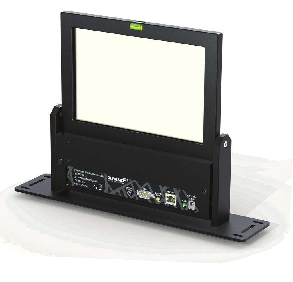
4 System Overview The XPAND Passive 3D Polarization Modulator Gen2 allows 3D DLP Ready projectors to project stereoscopic video in combination with circular polarized passive 3D glasses. This product uses the latest in LC shutter glass technology to give the best possible 3D experience with high brightness and contrast and no flickering. If you want to use your projector as a regular 2D DLP projector, you can move the XPAND Passive 3D Polarization Modulator out of the way of the projector lens allowing for a 2D projection at the projector s original brightness. Main features of the XPAND Passive 3D Polarization Modulator Gen2 are: High brightness and contrast ratio Control via string macros sent by a digital cinema server or projector Configurable operation using a dedicated PC-based configuration utility Service upgradable firmware Integrated LC shutter cooling fan Easy air filter cleaning and replacement What s Included (1) XPAND Passive 3D Polarization Modulator (1) Protective fabric cover for protecting the LC panel when not in use. (1) Power supply (DC 12V/1A) (2) GPIO cables for connecting the unit to the projector (1) Ethernet Crossover Cable (1) User Manual WARNING: The supplied Ethernet Crossover Cable should not be used as a regular network cable. It is intended primarily for direct connection of the modulator to a PC when performing network settings configuration if needed Connector Panel (1) Motion Control - Typically used for controlling a motorized mount, if the modulator is attached to one. See section Motion Control Output for more information. (2) GPIO - Connector for connecting the modulator to the projector. With use of special cables this connector can also be used for connecting the projector s or the digital cinema server s GPIO ports to the modulator. (3) SYNC / 3D MODE LED - Amber LED for indicating which mode the modulator is currently operating in. (4) ETHERNET - RJ45 / Ethernet port used for connecting the modulator to the local network. Two square LEDs are integrated in the connector, showing network activity of the unit. (5) STATUS LED - Green LED for indicating current status of the modulator. (6) DC12V 1A - Power in. Inputs GPIO Port: DSUB-9PIN-Male. See pinout diagram below for more information. Ethernet Port: RJ45 / 8P8C Ethernet connector. DC Power Jack: 6.2 mm Φ (Hole size), 1.6 mm Φ (Lead size). Mating connector: 5.5 mm Φ (OD), 2.1 mm Φ (Bore). XPAND, All Rights Reserved. 5
5 GPIO male 9-pin connector pinout Pin 1: SYNC IN (From projector) Pin 3: Trigger 1 (GPIO mode source control) Pin 4: Trigger 2 (Reserved) Pins 6, 8, 9: GND Pins 2, 5, 7: Not used Outputs Motion Control Port: Mating connector is either a stereo or mono 3.5 mm Φ plug. See section Motion Control Output for more information. LED Indications There are two LEDs on the unit which are used to indicate its status and mode: Green LED: STATUS LED. Indicates the status of the unit and used to identify errors. Amber LED: SYNC / 3D MODE LED. Indicates the mode in which the unit is currently operating. Additionally, the operation of the unit s cooling fan should be observed to determine which mode the modulator is operating in - see section Cooling Fan. LED indications given in below table can be encountered. For more information about different states corresponding to below LED indications see the rest of this manual. GREEN LED AMBER LED UNIT MODE AND STATUS OFF ON ON OFF OFF BLINKING (1s ON, 1s OFF) The unit is not operating. Either its power is unplugged or an unexpected error occurred and a hard reset must be made by removing and reapplying power. Cooling fan is off. The unit s mode control source is set to Network or GPIO. The unit can be in 2D or 3D mode (this is determined by observing the cooling fan operation - see section Cooling Fan). If the unit is in 3D mode (fan is operating), then no valid 3D sync signal is present. The unit s mode control source is set to frame sync, it is in 2D mode and scanning for a condition to transition into 3D mode. This condition is a valid 3D synchronization signal on the GPIO port. ON ON Normal 3D operation. The unit is in 3D mode and a valid 3D synchronization signal is detected. BLINKING BLINKING BLINKING BLINKING BLINKING BLINKING Simultaneous short blinking once every second of both LEDs indicates the device has encountered an error. A reset is required. The power supply should be unplugged for 5 s and then plugged back in. Alternating blinking of both LEDs indicates a start-up routine. When the unit is powered up it goes through an initialization sequence during which both LEDs blink out of phase for approximately 5 s. Simultaneous fast blinking of both LEDs indicates the unit has entered the factory reset routine. See section Factory Reset for more information. Cooling Fan The cooling fan MUST be operating when the modulator is exposed to light from the projector lamp. Exposing the modulator to light from the projector when the modulator is off or in 2D mode will result in heat damage to the LC shutter assembly. To avoid such damage, the modulator s cooling fan always turns on when operating in 3D mode. When the modulator is operating in 2D mode the cooling fan is off; therefore, cooling fan operation is a clear indication of which mode the modulator is operating in at any given time. If the fan is ON, the unit is set to 3D mode. If the fan is OFF, 2D mode is selected and the modulator must not be exposed to the light coming from the projector! 6
6 Operation Overview The main goal of the XPAND Passive 3D Polarization Modulator Gen2 unit is to modulate the light coming from the projector in a way which enables 3D viewing when using circular polarized passive 3D glasses. The modulation must be done in synchronization with the projector. To achieve this synchronization a 3D synchronization signal is fed from the projector to the modulator using one of the cables supplied with the modulator. Much of the modulator s operation can be configured over the network by using a dedicated PC-based configuration utility. See the Modulator Configuration Using the PC Based Configuration Utility section of this manual for more information. Factory Reset At any time the XPAND Passive 3D Polarization Modulator Gen2 can be reset to its factory default settings by following these steps: (1) Unplug all cables from the modulator. (2) Short pins 3 and 4 of the unit s GPIO port. (3) Plug the power back into the modulator. (4) Both LEDs on the unit should now be flashing quickly, indicating that a factory reset is about to be done. To confirm the factory reset, remove the short circuit between pins 3 and 4. The modulator will make two more slow flashes with both LEDs to indicate, that a reset has been made. To abort a factory default reset, unplug the power cord from the modulator and only then remove the short circuit. A reset is especially useful when performing network settings configuration if a mistake is made. A Factory Reset will return the modulator to its factory default settings, making the modulator again accessible at its default IP of Note that network settings of the unit will be reset as well so if its settings have been previously modified the modulator will now no longer be reachable and the network settings should be reconfigured. See section Unit s Initial Network Settings Configuration for more information. Modes of Operation The modulator operates in one of two modes: 2D mode or 3D mode. As their names suggest, the 3D mode is intended for watching 3D content and 2D mode for viewing 2D content at which point the modulator should be removed from in front of the projector. Which mode the modulator is operating in is determined by different conditions which depend on which mode control source is selected. See section Mode Control Sources for more information. The modulator signals if it is in 2D or 3D mode through its SYNC / 3D MODE LED, through its Motion Control Output and through the operation of its cooling fan. For more information see sections LED Indications, Motion Control Output and Cooling Fan. 2D Mode In 2D mode the modulator stops modulating its LC shutter, turns off the cooling fan and sets its Motion Control Output to 2D state (see section Motion Control Output for more details). A 2D state on the Motion Control Output triggers the movement of the unit away from the projector, if mounted onto a motorized mount connected to this output. In 2D mode the SYNC/3D MODE LED state depends on which mode control source is currently selected. See LED Indications and Mode Control Sources sections of this manual for more information. While in 2D mode, the unit continuously scans for conditions to transition to 3D mode. These conditions depend on which mode control source is selected - refer to section Mode Control Sources. 3D Mode In 3D mode the modulator turns on its cooling fan and sets its Motion Control Output to 3D state (see section Motion Control Output for more details). A 3D state on the Motion Control Output triggers the movement of the unit in front of the projector, if mounted onto a motorized mount connected to this output. If a valid 3D synchronization signal is fed from the projector to the modulator, the unit starts modulating its LC shutter and normal 3D viewing is possible. Validity of the signal is determined by f smin (3D Sync Low Threshold Frequency) and f smax (3D Sync High Threshold Frequency). See macros descriptions in section Network Mode Control Source and section Using the Configuration Utility. XPAND, All Rights Reserved. 7
7 In 3D mode the SYNC/3D MODE LED state depends on the presence of a valid 3D synchronization signal coming from the projector. If a valid 3D sync is detected, the LED is ON. If the signal is not present or is invalid, the LED is OFF. Note: When frame sync mode control source is selected, absence of a valid 3D synchronization signal automatically sets the mode to 2D. See the Mode Control Sources section of this manual for more information. While in 3D mode, the unit continuously scans for conditions to transition to 2D mode. The conditions depend on which mode detection method is selected - refer to section Mode Control Sources. Mode Control Sources The modulator has three ways of determining whether it should operate in 2D or 3D mode: (A) Detecting a valid 3D synchronization signal coming from the projector -> Frame Sync mode control source (B) Listening for a 3D or 2D command macro on the LAN -> Network mode control source (C) Triggering on a dedicated GPIO line of the GPIO connector -> GPIO mode control source Which one of the three mode control sources is active can be set using the modulator s PC-based configuration utility (see the Modulator Configuration Using the PC Based Configuration Utility section) or by sending a dedicated string macro command over the network from a projector or digital cinema server (see the modctrls command in section Network Mode Control Source). By default the Frame Sync mode control source is selected. Frame Sync Mode Control Source The default way of determining whether the modulator must begin operating in 3D mode is to monitor the 3D synchronization signal line coming from the projector for the presence of a valid synchronization signal. This signal comes into the modulator through its GPIO connector. If a valid signal is detected, the modulator transitions to 3D mode and stays there for as long as the signal is present. The 3D synchronization signal is a square wave. Whether a signal is valid or not is determined by measuring its frequency. By default all signals with a frequency between 35 Hz and 150 Hz are considered valid. However, these limits can be modified through the modulator s PC-based configuration utility. For more information see section Using the Configuration Utility. GPIO Mode Control Source If the modulator is set for GPIO Mode control source, the modulator then supports control over one GPIO line which is typically connected to one of the projector s or digital cinema server s GPIO lines. By default an externally applied open loop / open circuit between pins 3 and 8 sets 2D mode. Close circuit on those same pins sets 3D mode. Polarity can be inverted by using the PC-based configuration utility or by sending a dedicated command macro from the projector or the digital cinema server. An optically isolated open-collector or open drain GPIO control line needs to be connected between pins 8 and 3 to avoid damage to the modulator and/or projector - see the schematic below. Projectors and servers are typically equipped with such outputs so only a suitable passive cable is required. Alternatively CMOS levels with a 3.3 V supply can be used with pin 8 connected to GND. However optically isolated lines are preferred. XPAND Passive 3D Polarization Modulator +3V3 10k 1 Projector or Digital Cinema Server GPIO 6 2 1k GND V3 D-SUB 9 Male GND GND GND GND 8
8 Network Mode Control Source If the modulator is set for this mode control source, the modulator then accepts command macros from over the network, signalling it to move to 3D or 2D mode. This method is intended for controlling the modulator and the optional motorized mount connected to it over the network, by a projector or digital cinema server. The unit s network settings must first be configured so that the modulator is accessible over the network. For information on how this is done see section Unit s Initial Network Settings Configuration. Once the modulator s network settings have been properly configured, the modulator s mode can be controlled by sending string macros to its IP address on port Macros are simple strings sent to the unit s IP address and take the following form: <command>parameter</> Examples: 2D mode command macro string: <mode>2d</> 3D mode command macro string: <mode>3d</> The 2D and 3D macros are not the only ones which are accepted by the XPAND Passive 3D Polarization Modulator Gen2. The table below summarizes all string macros which are recognized. Most are accepted no matter which mode control source is selected whereas some only have effect if Network is selected as the mode control source. The modulator accepts up to 8 commands in one string: <command1>parameter1<command2>parameter2 <command8>parameter8</> Below example shows a string macro made up of two commands - the command to set the mode control source to Network and then set the modulator to 3D mode: <modctrls>n<mode>3d</> Command Parameter Value Description mode syncpol modctrls 2D / 3D norm / inv f / n / g Sets the currently active mode based on the input parameter value. Note: This command only takes effect if the Network Mode Control Source is selected. If Frame Sync or GPIO mode control sources are selected, the command is ignored. Sets polarity of 3D sync signal and thereby determines whether high level of the 3D frame synchronization square signal corresponds to the left eye 3D image or the right one. Sets the active mode control source. f Frame sync mode control source n Network mode control source g GPIO mode control source f smin * Sets the minimal frequency of 3D sync signal at which the system operates in 3D mode. This value is only used if Frame sync is set as mode control source. For Network and GPIO mode control source this frequency is hardcoded to 20 Hz. f smax * Sets the maximum frequency of 3D sync signal at which the system operates in 3D mode. This value is only used if Frame sync is set as mode control source. For Network and GPIO mode control source this frequency is hardcoded to 160 Hz. gpiopol norm / inv Sets the polarity of the GPIO input signal. * Parameter f smin must be lower than f smax Note that there is a known issue when connecting the modulator to Doremi and NEC digital cinema servers which must surround the string macro with \w (without quotes) to ensure proper operation. This introduces a short delay when sending the macro over the network which gives the modulator enough time to receive the command before the server disconnects. An example of a macro which puts the modulator in 3D mode if the Network Mode Control Source is selected is \w<mode>3d</>\w (without quotes). XPAND, All Rights Reserved. 9
9 Motion Control Output In a typical setup the modulator is mounted onto a motorized mount unit which can automatically move the modulator in front of and away from the projector. The Motion Control Output on the modulator is intended for connecting the unit to such a mount. It is through this port that the modulator signals the mount to move it away from the projector when operating in 2D mode and to move it in front of the projector when in 3D mode. The Motion Control Output is an open collector, optically isolated output - see below diagram. By default the output is open when in 3D mode and closed/shorted when in 2D mode. This polarity can however be reversed by using the PC-based configuration utility. See section Device General Settings, parameter Motion Control Polarity. Stereo Phone Jack Setup and Configuration Installation 1. Before starting the installation process make sure the unit is turned OFF and power is unplugged. 2. Turn off the projector which will have the XPAND Passive 3D Polarization Modulator Gen2 installed in front. 3. Position the polarization modulator in front of the projector lens. The side of the modulator which contains the connectors must be facing towards the projector! Check the spirit level on the top of the shutter glass to make sure it is parallel to the ground. Also make sure that there is enough space in front of the modulator s air filter to allow for sufficient air flow and LC shutter cooling. WARNING: The distance between the projector lens and the shutter glass of the modulator must be at least 15 cm (app 6 inches)! Failure to follow this instruction may cause permanent damage to the modulator and is not covered by warranty. If the modulator is mounted on a motorized mount unit, the mount should be installed first. The final setup must take into account above required position of the modulator. 4. Connect one of the supplied GPIO cables to the GPIO connector on the projector and to the 9 pin GPIO connector on the back of the modulator. Two cables are supplied with the modulator. Choose the correct one based on the available connectors on the projector. 5. If the modulator unit will be controlled or configured over the network, first configure its network settings. For information on how to do this see section Unit s Initial Network Settings Configuration. Then connect the modulator to the network using a standard RJ45 Ethernet cable. Alternatively, the modulator can be connected directly to the projector or digital cinema server by using an Ethernet crossover cable if both are configured properly. Note that some projectors or digital cinema servers may have more than one RJ45 port and some may be used for other applications. Make sure to use the one intended for network connection. 6. If the modulator is mounted on a motorized mount, go through the Motion Control Setup Wizard described below to properly configure the way the modulator moves away and in front of the projector. This step is imperative to avoid damage to the modulator s LC shutter in the event it would not be moved away from in front of the projector when the modulator s fan is turned off and the projector s lamp remains ON. 7. Connect the supplied 12 V/1A power cord to the DC input connector on the back of the modulator. 8. Use a calibration picture of your choice to test proper operation and fine tune the position of the modulator s LC shutter glass, so that it is exactly perpendicular to the incoming light from the projector, thereby eliminating the artefacts on the screen caused by light reflections from the shutter glass. Also verify proper polarity of the 3D image. Calibration image s left eye reference must be seen through the left lens. If this is not the case, invert the 3D sync signal polarity either on the projector or by using the PC configuration utility - see section Using the Configuration Utility, part Device General Settings. WARNING: If not using a motorized mount unit, the modulator must be manually moved away from the projector every time the projector is not used for 3D viewing! 10
10 Motion Control Setup Wizard The process below should be carried out when installing the XPAND Passive 3D Polarization Modulator Gen2, if it is mounted on a motorized mount unit. Such setup is crucial to ensure that the modulator is moved away from the projector automatically by the mount when the projector is used for 2D viewing. Likewise the mount automatically moves the modulator in front of the projector when in 3D mode. Keeping the modulator in front of the projector when viewing in 2D degrades image quality and may cause heat damage to the lens which is not cooled in 2D mode. It is strongly recommended that XPAND s Passive 3D Polarization Modulator Motorized Mount is used in combination with the modulator. The use of XPAND s motorized mount is assumed in below setup steps. To ensure the mount always moves the modulator out of the way of the projector s light path when in 2D mode, first complete steps 1 through 5 above and then continue with steps listed below before proceeding to step 7. Warning: This process is valid only when installing a new unit which has not yet been re-configured and is still set to factory default settings. If the unit has already been re-configured and is moved to another projector, it should first be set to its factory default state before proceeding with below steps. Factory default settings can be set by using the PC configuration utility or by performing a factory reset - see the Factory Reset section for more information. Note however, that when performing a full factory reset as described in section Factory Reset, network settings are reset as well and will have to be reconfigured again to make the modulator accessible on the network. 6a. Disconnect power from both the modulator and the motorized mount unit. 6b. Connect the modulator s Motion Control Output to the mount by using a mono or stereo cable supplied with the motorized mount. 6c. Apply power to both units and wait for both to stop moving. 6d. Block the light path from the projector so that the light from its lamp cannot reach the modulator by placing a non-transparent light barrier between the projector and the modulator. Alternatively the lamp on the projector can be turned off or if the projector allows it, its shutter (aka dowser) can be closed. 6e. Turn on the projector and start showing 3D content. 6f. Both the green and yellow LED on the modulator need to be turned ON. If the mount starts moving, wait for it to stop. 6g. At this point the modulator must be located in front of the projector and its cooling fan must be operating! The modulator is in 3D mode and a 3D image can be seen if using passive 3D glasses and unblocking the light from the projector. If the modulator is not located in front of the projector, its 3D position needs to be inverted either on the modulator OR on the motorized mount unit. Not on both! a. To invert the positions on the modulator first connect to it using the PC based configuration utility. For this the unit must be connected to a local network (LAN). See section Modulator Configuration Using the PC Based Configuration Utility for more information on how to connect to the modulator. Once connected, invert the 2D and 3D positions by selecting Inverted next to the Motion Control Polarity parameter. At that point the modulator should start moving in front of the projector. b. To invert 3D and 2D positions on the motorized mount consult its user manual. 6h. Stop the 3D content on the projector and start showing 2D content. 6i. At this point the modulator should start moving away from the projector. The modulator is in 2D mode and its cooling fan is turned off. To prevent damage to the modulator it is imperative that it is not located in front of the projector when its cooling fan is off! Unit s Initial Network Settings Configuration This section describes how to configure the network settings on a new XPAND Passive 3D Polarization Modulator Gen2 unit so that it is accessible on a local area network. If more modulators are to be connected to the same network only one should be connected at a time while performing network configuration. It is suggested you consult your IT department and verify if configuring the modulator according to the below described procedure is compatible with your local network structure and organization. XPAND, All Rights Reserved. 11
11 A unit configured to its factory default settings has a default static IP address of and a network mask of Such configuration will make the device accessible on any local network which uses an IP address range of * and on which the address is not yet used. Many routers use this address space by default so chances are that the modulator will be accessible out of the box if connected to such a network. However there is also a high chance that the network on which the modulator is connected does not use this range of IP addresses and so the unit s default static IP is not supported. In such a case the modulator can be accessed by directly connecting it to a PC using an Ethernet crossover cable supplied with the unit and properly configuring the network settings on the PC. The following steps need to be taken to make an initial connection to the unit and configure its network settings: 1. First, try connecting the unit directly to the local network to which it will be connected during normal operation. 2. Download the XPAND Passive 3D Polarization Modulator Gen2 Configuration Utility from XPAND s website, install it on your PC and run it. 3. Select Factory default device from the Select Device drop-down list. This list contains all devices known to the utility and should only contain the Factory default device after a fresh install. 4. After confirming the selection an automatic attempt to connect to the modulator will be made. This is indicated in the status bar at the bottom of the utility which should read Please stand by. Retrieving device data.... If an automatic connection attempt is not made by the utility, initiate it manually by clicking the Get Device State button. 5. Two situations are possible after initiating a connection: a. If the application successfully connected to the modulator, then information about the unit will be displayed by the application and the status bar will read Device found. Application idle.. In this case the modulator s default IP is within the network s IP range and the modulator is accessible on that network. If you plan on using only one modulator on this network then the IP can be left unchanged but must be reserved on the network to avoid it being assigned to another device when the modulator is powered off or disconnected from the network. Consult your IT department on how to reserve an IP address on your local network. Chances are that this can be configured on the router however configuration elsewhere on the network may be required. Once the IP is reserved, network configuration is finished. If however more modulators will be connected to the same network, this unit s IP must be changed since each modulator requires a unique IP. Proceed to step number 6. b. The application failed to connect to the modulator (status bar reads Device not found on LAN. ). First try to connect a few more times manually by pressing the Get Device State button. Also try restarting the modulator by unplugging it from power, waiting for 5 s and then plugging it back in. If this does not help, then the default IP address of the modulator probably does not match the available IPs allowed by the local network to which it is connected. To establish a connection with such a modulator a direct connection with your PC is needed: Unplug the network cables from the modulator and from the PC. On your PC, change your network settings and assign your PC a static IP address of and a network mask of It is important that the IP address has the first three numbers equal to the first three numbers of the modulator s IP address. These numbers are when it is configured to factory default settings. For Windows 7 PC reconfiguration can be done by following below steps: Go to Control Panel -> Network and Sharing Center -> Change adapter settings Right-click on Local Area Connection and select Properties Select Internet Protocol Version 4 (TCP/IPv4) and click on Properties Remember the settings shown in the General tab. You will need to restore them once you finish configuring the modulator. In the General tab select Use the following IP address and enter an IP of , and a network mask of The Default gateway field can be left empty. Also select the Use the following DNS server addresses but leave the fields empty. Click OK and then Close Connect the modulator to the PC using an Ethernet crossover cable which is supplied with the modulator. From the configuration utility retry connecting to the modulator. Only proceed to step 6 once a successful connection to the modulator has been made. 6. At this step a successful connection has been made to the modulator by using the XPAND Passive 3D Polarization Modulator Configuration Utility. Its IP address now needs to be changed to a valid IP for the network on which the modulator will be located during normal operation. First, one such IP address must be found. If possible, you should consult your IT department and have them assign and reserve a free IP address which can be permanently used by the modulator. Alternatively you can try and reserve an IP for the modulator yourself by properly configuring the network. In some cases all that is needed is reserving the IP address on the router, if the modulator is connected to one and the network is configured ac- 12
12 cordingly (see the router s user manual for more information). However, depending on your network s configuration, IP address reservation may need to be done elsewhere on the network. 7. After step 5, the XPAND Passive 3D Polarization Modulator Configuration Utility should still be connected to the modulator and its IP address can now be updated with that acquired in step 6. To do so press the Change Network Settings on Device button. This enables changing of network settings on the connected modulator, including its IP address. Enter the new IP address from step 6 in the Device IP field. If the modulator and the device which will be controlling it are on the same subnetwork then the network mask should be set to and the default gateway setting is not critical. However if they are on different subnetworks, the mask and default gateway should be configured properly based on your network s structure. Consult your IT department for help. 8. To send the new IP and other network settings to the modulator press the Confirm New Network Settings button. Warning! If you assign an invalid address to the modulator you will no longer be able to access it over the network! You will be able to access it again by connecting it directly to your PC as described in step 5b) if setting the PC s static address so that the first three numbers are the same as those of the modulator s IP which you have just set. So if you set the modulator s IP address to you will only be able to access it directly from your PC as described in 5b), if setting the PC s static IP address to * (excluding ). 9. Since the modulator s IP has now been changed a new device must be added to the list of known devices inside the configuration utility. Click the Add new device link and enter a device name, its new IP and make sure the port is set to An attempt to connect to this device will then be made. If you were configuring the modulator by direct connection with a crossover cable this attempt will fail and you have to connect the modulator and the PC to their respective networks (make sure to first reset you PC network settings you may have changed in step 5b).If an automatic connection attempt is not made by the utility, initiate it manually by clicking the Get Device State button. Once a successful connection is made, device information read from the unit will be updated in appropriate fields of the configuration utility. Note: The network may require some time to refresh its list of known devices and accept the new IP address for the modulator. If reconnection fails, try waiting a minute or two before trying again. You can also disconnect the device from the network during that time. Recommended Projector Settings for XPAND Passive 3D Cinemas Dark time: 700 µs Output reference delay: -100 µs Parameters listed below are more a function of the DCI server and/or the projector than a function of the modulator so given values should be taken as reference and modified if the expected results are not obtained: L/R Output Reference Polarity: Inverted (change, if 3D image appears inverted). L/R Display Reference: Not Used L/R Input Reference: Use input reference - frame seq mode (polarity = true) Input frame dominance: Left (L1R1 L2R2) Modulator Configuration Using the PC Based Configuration Utility Overview The XPAND Passive 3D Polarization Modulator Gen2 features a PC-based setup and configuration utility which can be used for changing advanced settings on the unit. The modulator s default settings enable it to work out of the box so no configuration is required. However, based on the system with which the modulator is used, some settings may need to be changed to ensure desired operation. The PC configuration utility is subject to updates so make sure to check the help file bundled with each release for up to date information about its features and functionality! As shown in below image, the configuration utility is made up of six parts: (1) Device Selection - Selecting and connecting to a modulator. (2) Device Network Settings - Modulator s network settings information and control. (3) Device Information - General information about the connected modulator. (4) Device General Settings - Information and control of connected modulator s general settings. (5) Device Mode Control Settings - Information and control of connected modulator s settings pertaining to its mode control source. (6) The Menu Bar - Additional features related to the configuration utility and connected modulator. XPAND, All Rights Reserved. 13

13 Using the Configuration Utility The list below only gives a general description of configuration utility s features. For a more detailed and up to date explanation see the configuration utility s help file. Device Selection and Connection In a common setup a cinema theatre will have more than one cinema hall equipped with XPAND s passive modulators and the operator will be able to access all of them from the same PC. To distinguish between all connected modulators a known devices list needs to be maintained. This section is used to manage such a list of known devices, connect to them and display and change the information about each one. The section features the following controls: Select Device drop-down list: Used to select a device to connect to from a list of devices known to the utility. Devices must be added manually. See Add new device control description below. Get Device State button: By pressing this button the utility attempts to connect to the currently selected device and retrieve its configuration which it then displays. Device info: Clicking on this control displays information about network parameters of the device currently selected in the Select Device drop-down list as known to the configuration utility. A pop-up window which displays this information also allows modifying these parameters in the list. Note that if the actual settings of the unit are modified from PC A, the ones stored by the configuration utility on PC B will have to be modified manually through the Device Info pup-up window. 14
14 Add new device: Opens a pop-up window which can be used to enter network parameters of a new device and add it to the list of known devices. Delete selected device: Deletes the currently selected device from the list of known devices. Device Network Settings This section displays the connected modulator s network settings as set on the device and also allows changing them. The fields and controls listed below make this possible. WARNING: Modifying device network settings can make the device unreachable over the network if the wrong values are used. It is advised you consult with your IT department before making any changes. New devices on the network may be blocked by the local network if strong security is implemented. Your IT department must add the new device to their known devices list in order for them to be reachable over the network. Change Network Settings on Device button: If a device is connected, pressing this button enables the user to modify network settings on the modulator. Its IP address, network mask and default gateway can be changed. Once the button is pressed, the Device IP, Device Network Mask and Device Default Gateway information becomes editable, the button is transformed into a Confirm New Network Settings button and an additional Abort button is shown. When new values are entered they are sent to the device by pressing the Confirm New Network Settings button. The process is aborted by pressing the Abort button. Device IP: Displays the IP address of the currently connected device. Device MAC: Displays the MAC address of the currently connected device. Device Network Mask: Displays the network mask of the currently connected device. Device Default Gateway: Displays the default gateway of the currently connected device. Device Information This section displays general information about the connected modulator. Device ID: Displays the ID of detected device (e.g. XPS2A). Firmware Version: Used to identify the FW version loaded onto the modulator. Current 3D Sync Frequency: Reports whether a synchronization signal is detected on the modulator s 3D sync GPIO input. Validity of the signal and its frequency are reported. Whether a signal is valid or not is determined based on the currently set low and high frame sync frequency settings. See parameters for 3D Sync Low Threshold Frequency and 3D Sync High Threshold Frequency described below. Current Mode: Reports whether the connected modulator is currently operating in 2D or 3D mode. GPIO Logic Level: Displays the logic level detected on GPIO input and the resulting mode of operation (e.g: Open Loop, 2D). Note that the mode reported here may not be the same as the Current Mode described above if a control source other than GPIO is selected. Device General Settings This section displays and enables modification of general settings of the connected modulator. 3D Sync Signal Polarity: Can be used to determine and change the interpretation of the incoming 3D sync synchronization signal s levels. Normal setting interprets a high level of the synchronization signal as corresponding to the left eye 3D image. If set to Inverted, the high level is interpreted as corresponding to the right eye 3D image. So this parameter can be used to invert the left and right eye 3D images if needed. This is usually done when 3D content seems unnatural and uncomfortable. Motion Control Polarity: Polarity of the motion control output signal. See section Motion Control Output for more information. WARNING: This parameter should not be used as a way of changing the modulator s position!!! This is a global setting which should be configured if needed when first installing the modulator on a motorized mount in front of the projector. See the Installation -> Motion Control Setup Wizard section of this manual for more information on how to properly set up and configure the modulator and motorized mount. Global Delay: Delay between the 3D sync edge and the start of the left/right-eye open intervals. Valid values are between µs. Default value is 120 µs. If the value exceeds the current value of the frame synchronization signal period, the delay parameter is ignored. To set global delay on the modulator, enter a new value and press the Enter key to confirm the change. XPAND, All Rights Reserved. 15
15 Device Mode Control Settings This section displays and enables modification of settings relating to control of conditions which have to be met in order for the modulator to transition between 2D and 3D modes. Mode Control Source: Defines the mode detection method or in other words the source which determines whether the unit should operate in 2D or 3D mode. See the Mode Control Sources section of this manual for more information on each mode control source. GPIO Signal Polarity: Determines how the GPIO mode control source s input state is interpreted. Normal polarity means that an externally applied short circuit between pins 3 and 8 sets 3D mode. Inverted setting interprets that same short circuit as 2D mode. 3D Sync Low Threshold Frequency: For Framesync mode control source this value sets the minimal frequency at which the incoming 3D synchronization signal is still considered as valid. If the unit is in 3D mode and the frequency is above this limit (and below the high threshold - see next parameter), the modulator starts its LC shutter and 3D viewing is possible. Valid values are between 24 and 160 Hz with a requirement that the low threshold frequency is lower than the high threshold frequency - see next parameter. For Network and GPIO mode control source this frequency is hardcoded at 20 Hz. To set the low threshold frequency on the modulator, enter a new value and press the Enter key to confirm the change. 3D Sync High Threshold Frequency: Maximal frequency at which the incoming 3D synchronization signal is still considered as valid. If the unit is in 3D mode and the frequency is below this limit (and above the low threshold - see previous parameter), the modulator starts its LC shutter and 3D viewing is possible. Valid values are between 24 and 160 Hz with a requirement that the high threshold frequency is higher than the low threshold frequency - see previous parameter. For Network and GPIO mode control source this frequency is hardcoded at 160 Hz. To set the high threshold frequency on the modulator, enter a new value and press the Enter key to confirm the change. The Menu Bar Most of the menu s items are self-explanatory and intuitive. However the following submenu items deserve some additional explanation: Restore Default Settings: Selecting this item enables resetting the currently connected modulator to its default settings. Note that the network settings remain unchanged and only the functional ones are reset. Resetting also the network settings would very likely make the modulator not accessible on the network without repeating the initial network settings configuration again. If a reset of network settings is required, a full factory reset of the modulator should be performed. See section Factory Reset for instructions on how that is done. Check for Updates: By selecting this submenu item, the application connects to XPAND s server and checks if any updates are available for the configuration utility. If a newer version of the utility exists, the user can choose to download and install it. During the installation, the previous current version will be uninstalled. It is advised that you regularly check XPAND s website for new releases, especially if you experience issues with the existing version. Maintenance LC Shutter Cleaning The modulator s LC shutter should be examined regularly for dirt, dust or stains. A clean LC shutter is important for obtaining a clean and sharp 3D image. The preferred method for cleaning the shutter is to use compressed air of low pressure. This removes any dirt and dust. For removing stains such as fingerprints and smudges clean the LC shutter by wiping the panel lightly with a smooth, dry cloth to prevent any scratches. If needed, the used cloth can be slightly damp. After cleaning make sure the panel is still positioned correctly. Check the spirit level for horizontal alignment and use a calibration picture to fine-tune the position the shutter if necessary. Fan Air Filter Cleaning and Replacement The modulator features an easy to replace and clean dust filter which protects the fan cooling the LC shutter. With time the filter can become clogged with dust and other airborne contaminants, which deprive the LC shutter of fresh air required for proper cooling. Insufficient 16
16 cooling of the LC shutter will result in poor optical characteristics and may eventually lead to LC damage. Because of this the filter should be cleaned regularly. To clean the filter, first unplug the power from the unit. Next, place the protective cover on the modulator to prevent fingerprints or smudges from getting on the polarizer, then slide the filter out of the unit and remove the filter from its holder. Clean the filter by blowing air through it either by using an air compressor or a vacuum cleaner. If needed, wash the filter under water. Make sure the filter is completely dry before inserting it back into the unit! Remove the protective cover and plug the power jack back into the modulator. If the filter shows sign of wear, it should be replaced. Product Specifications Product Name Model Name Active Area Polarization Transmittance Efficiency Response Time Input Stereo Sync Signal Frequency Input Terminal 3D Input LAN XPAND Passive 3D Polarization Modulator Gen2 MS210C2 210 mm x 135 mm (8.3 x 5.3 ), dual pi-cell technology Circular Polarization (Circular Polarization Glasses) 40% (± 1%, may differ depending on the screen) 16% (varies with type of passive glasses used) < 1 ms 24 Hz to 160 Hz, HFR support GPIO 9 pin DB9 male connector. Converter cables to DB15 and DB37 connectors commonly found on projectors are included. 8P8C (RJ-45/Ethernet) Connector XPAND, All Rights Reserved. 17
17 MOTION CONTROL Output Terminal STATUS LED SYNC / 3D MODE LED Weight Stereo (a cable with stereo or mono 3.5 mm plug can be used) LED Indication - Green LED Indication - Amber 1.8 +/- 0.1 kg (app. 4 lbs) - accessories not included Window Module: 253 x 176 x 13 mm (10 x 6.9 x 0.5 ) - Width x Height x Depth Size Control board with stands: 277 x 130 x 47 mm (10.9 x 5.1 x 1.9 ) - Width x Height x Depth Base plate: 380 x 4 x 80 mm (15 x 0.2 x 3.1 ) - Width x Height x Depth Storage Temperature Operating Temperature Material Colour Power Source Power Consumption -10 ~ 60 ºC (14 ~ 140 F) noncondensing! 10 ~ 60 ºC (50 ~ 140 F) - noncondensing! Case Material (Main material): Aluminium Black AC adapter 12 V/1A 3D operation: 4.2 W 2D mode: 1.2 W General Health and Safety Warnings 1. May Trigger Seizures Some people have a condition that can cause them to experience seizures or lose consciousness momentarily while viewing certain kinds of flashing lights or patterns. These persons may have seizures while watching certain kinds of television pictures or playing certain video or computer games. Persons who have not had any previous seizures may still have an undetected seizure condition. People who have experienced symptoms linked to a seizure condition, including experiencing seizures or loss of awareness, or people with family members who have experienced such symptoms, should consult their physician before viewing 3D media. We recommend that Parents or Guardians observe their children while the children view 3D content. 3D content viewing should immediately be discontinued in case adults or children experience any of the following symptoms: dizziness, altered vision, eye or muscle twitching, involuntary movements, loss of awareness, unconsciousness, disorientation, or seizures. Do not view 3D content for extended periods of time. 2. May Cause Eye Fatigue Some users have reported dizziness, headaches, or eye fatigue as a result of viewing media in 3D. 3D content viewing should immediately be discontinued in case adults or children experience any of these conditions. Do not view 3D content for extended periods of time. Parents or Guardians should limit use by children to no more than a few hours per day. 3. Young Children The vision of young children (especially children under the age of six) is still under development. Consult your doctor (such as a paediatrician or eye doctor) before allowing young children to watch 3D video images or play 3D videos games. Parents or Guardians should supervise young children to ensure they follow these recommendations. 4. Choking hazard: Keep out of reach of small children. Babies and young children could choke on small pieces associated with 3D glasses and related equipment. Keep the 3D polarization modulator and 3D glasses out of reach of small children. 18
18 5. Stereoscopic viewing may cause a slight after-effect in vision. Your eyes change to accommodate viewing through 3D glasses. Wait a few moments after you remove the 3D glasses for your eyesight to return to normal before resuming your regular activities. 6. Do not use 3D glasses for purposes other than viewing 3D visual content. Do not wear 3D Glasses as sunglasses or safety glasses. Never wear 3D glasses while driving, swimming, or operating machinery. Do not use near staircases, ledges or balconies. You may risk falling during or after use. Regulatory Compliance Statements Caution: Any changes or modifications to this equipment not explicitly approved by X6D Limited shall void the user s authority to operate it. This device complies with part 15 of the FCC Rules. Operation is subject to the following two conditions: (1) This device may not cause harmful interference, and (2) this device must accept any interference received, including interference that may cause undesired operation. Hereby X6D Limited declares that the MS210C2 is in compliance with the essential requirements and other relevant provisions of the EU Directive 2004/108/EC. The declaration of conformity may be consulted at Copyright The contents stated herein are the property of X6D Ltd.. All rights reserved. Any unauthorized copy, reproduction, distribution, publication, display, modification, transmission or quoting of any part of this manual is strictly prohibited and will be prosecuted to the maximum extent possible. UMA5-V2-ENG XPAND, All Rights Reserved. 19

19
SmartCrystal Cinema Neo
 Model VPSP-11100 www.volfoni.com 1 SUMMARY SUMMARY... 2 I. PRODUCT OVERVIEW... 3 II. REQUIREMENTS... 3 III. SMARTCRYSTAL CINEMA NEO FEATURES... 5 A. General specifications... 5 B. Technical specifications...
SMART CINEMAHORIZONTAL. User Guide VPSP Projector side. model. Notice SmartCrystal Cinema MUV V1R0
 SMART User Guide CINEMAHORIZONTAL Projector side Notice SmartCrystal Cinema MUV130054-V1R0 model VPSP-05000 ENGLISH SUMMARY Content Page 1. PRODUCT OVERVIEW 3. 2. REQUIREMENTS 3. 3. SmartCrystal Cinema
SmartCrystal Cinema Neo
 USER MANUAL Date : 5/04/2016 Model VPSP-11000 www.volfoni.com 1 USER MANUAL Date : 5/04/2016 SUMMARY I. PRODUCT OVERVIEW...3 II. REQUIREMENTS...3 III. SMARTCRYSTAL CINEMA NEO FEATURES...5 A. General specifications...5
FS3. Quick Start Guide. Overview. FS3 Control
 FS3 Quick Start Guide Overview The new FS3 combines AJA's industry-proven frame synchronization with high-quality 4K up-conversion technology to seamlessly integrate SD and HD signals into 4K workflows.
ALO 030 MKII. 30 Watt DMX LED scanner. User manual
 ALO 030 MKII 30 Watt DMX LED scanner User manual Safety instructions WARNING! Always keep this device away from moisture and rain! Hazardous electrical shocks may occur! WARNING! Only connect this device
FS1-X. Quick Start Guide. Overview. Frame Rate Conversion Option. Two Video Processors. Two Operating Modes
 FS1-X Quick Start Guide Overview Matching up and synchronizing disparate video and audio formats is a critical part of any broadcast, mobile or post-production environment. Within its compact 1RU chassis,
KINOPROKAT 3D-POLARCP.V3 USER MANUAL
 KINOPROKAT 3D-POLARCP.V3 USER MANUAL Contents Introduction 1. Technical specification 2. Security regulation 3. System installation 3.1. components 3.2 system assembly 3.3 placement instruction for projection
FS4 Quick Start Guide
 FS4 Quick Start Guide Overview FS4 is AJA s flagship frame synchronizer and converter, offering incredible versatility and connectivity in a sleek and compact 1RU frame for all your 4K/ UltraHD/2K/HD/SD
INFORMATION TO USER CAUTION RISK OF ELECTRIC SHOCK, DO NOT OPEN
 INFORMATION TO USER CAUTION RISK OF ELECTRIC SHOCK, DO NOT OPEN! CAUTION: TO REDUCE THE RISK OF ELECTRIC SHOCK, DO NOT REMOVE COVER (OR BACK). NO USER SERVICEABLE PARTS INSIDE. REFER SERVICING TO QUALIFIED
-TECH DIGITAL. Explore The High DefinitionWorld. Website: Hot Line: [US] USER MANUAL
![-TECH DIGITAL. Explore The High DefinitionWorld. Website: Hot Line: [US] USER MANUAL](/thumbs/80/80689593.jpg "-TECH DIGITAL. Explore The High DefinitionWorld. Website: Hot Line: [US] USER MANUAL") -TECH DIGITAL Explore The High DefinitionWorld Website: www.jtechdigital.com Hot Line: 1-888-610-2818[US] USER MANUAL J-Tech Digital ProAV H.264 Encoder/Decoder Many to Many HDMI Extender RoHS 1 Operating
-TECH DIGITAL Explore The High DefinitionWorld Website: www.jtechdigital.com Hot Line: 1-888-610-2818[US] USER MANUAL J-Tech Digital ProAV H.264 Encoder/Decoder Many to Many HDMI Extender RoHS 1 Operating
17 19 PROFESSIONAL LCD COLOUR MONITOR ART
 17 19 PROFESSIONAL LCD COLOUR MONITOR ART. 41657-41659 Via Don Arrigoni, 5 24020 Rovetta S. Lorenzo (Bergamo) http://www.comelit.eu e-mail:export.department@comelit.it WARNING: TO REDUCE THE RISK OF FIRE
DDW36C Advanced Wireless Gateway - Safety and Installation Product Insert. Federal Communications Commission (FCC) Interference Statement
 Interference Statement") DDW36C Advanced Wireless Gateway - Safety and Installation Product Insert Federal Communications Commission (FCC) Interference Statement This equipment has been tested and found to comply with the limits
DDW36C Advanced Wireless Gateway - Safety and Installation Product Insert Federal Communications Commission (FCC) Interference Statement This equipment has been tested and found to comply with the limits
Gigabit Multi-mode SX to Single Mode LX Converter. User s Manual NGF-728 Series. Warning COPYRIGHT
 COPYRIGHT Gigabit Multi-mode SX to Single Mode LX Converter User s Manual NGF-728 Series All rights reserved. No part of this publication may be reproduced, stored in a retrieval system, or transmitted
DX-10 tm Digital Interface User s Guide
 DX-10 tm Digital Interface User s Guide GPIO Communications Revision B Copyright Component Engineering, All Rights Reserved Table of Contents Foreword... 2 Introduction... 3 What s in the Box... 3 What
CI-218 / CI-303 / CI430
 CI-218 / CI-303 / CI430 Network Camera User Manual English AREC Inc. All Rights Reserved 2017. l www.arec.com All information contained in this document is Proprietary Table of Contents 1. Overview 1.1
User Manual K.M.E. Dante Module
 User Manual K.M.E. Dante Module Index 1. General Information regarding the K.M.E. Dante Module... 1 1.1 Stream Processing... 1 1.2 Recommended Setup Method... 1 1.3 Hints about Switches in a Dante network...
CDV07. Analog video distribution amplifier(s)
") CDV07 Analog video distribution amplifier(s) TECHNICAL MANUAL CDV07 Analog video distribution amplifier Lange Wagenstraat 55 NL-5126 BB Gilze The Netherlands Phone: +31 161 850 450 Fax: +31 161 850 499
CDV07 Analog video distribution amplifier(s) TECHNICAL MANUAL CDV07 Analog video distribution amplifier Lange Wagenstraat 55 NL-5126 BB Gilze The Netherlands Phone: +31 161 850 450 Fax: +31 161 850 499
BRIGHTLINK HDMI EXTENDER OVER ETHERNET - H METER MODEL: BL-EXT-IP-264
 BRIGHTLINK HDMI EXTENDER OVER ETHERNET - H.264-120 METER MODEL: BL-EXT-IP-264 Operating Instructions BRIGHTLINKAV.COM 1 Introduction This HDMI over IP Extender use the advanced H.264 as the compression
SAT IF distribution system
 7. Technical specifications Type cs43 RF input frequency range pr. 50-350 MHz inputs number 4 level pr. 55...88 dbµv 60...93 dbµv symbol rate 3 45 Ms/s return loss/impedance > 0 db/75 Ω LNB powering/control
Quick Start Guide Operators
 Projector Components Left Side Cover Rear Cover High voltage and strong UV radiation is present in these projectors! To prevent personal injury, electrical shock, exposure to UV radiation and fire hazard,
SAFETY WARNINGS AND GUIDELINES
 SAFETY WARNINGS AND GUIDELINES Please read this manual thoroughly, paying extra attention to these safety warnings and guidelines: Do not expose this monitor to water or moisture of any kind. Do not handle
Troubleshooting. 1. Symptom: Status indicator (Red LED) on SSR is constant on. 2. Symptom: Output indicator (Yellow LED) on SSR is flashing.
 on SSR is constant on. 2. Symptom: Output indicator (Yellow LED) on SSR is flashing.") Product Data Electrical Data SST (Transmitter) SSR (Receiver) Supply voltage 18 30 V dc Max. Voltage ripple 15 % (within supply range) Current consumption 100 ma (RMS) 75 ma Digital - 100 ma Max. outputs
Product Data Electrical Data SST (Transmitter) SSR (Receiver) Supply voltage 18 30 V dc Max. Voltage ripple 15 % (within supply range) Current consumption 100 ma (RMS) 75 ma Digital - 100 ma Max. outputs
PLEASE READ THIS PRODUCT MANUAL CAREFULLY BEFORE USING THIS PRODUCT.
 Features The AVG-HD400 is an HDBT 2.0 transceiver set which contains a transmitter and a receiver. Compliant with HDMI 1.4 & HDCP 2.2, it is able to transmit high-definition signals up to 4Kx2K@60Hz. The
USER MANUAL. 27 Full HD Widescreen LED Monitor L270E
 USER MANUAL 27 Full HD Widescreen LED Monitor L270E TABLE OF CONTENTS 1 Getting Started 2 Control Panel/ Back Panel 3 On Screen Display 4 Technical Specs 5 Care & Maintenance 6 Troubleshooting 7 Safety
LA1500R USER S GUIDE.
 LA1500R USER S GUIDE www.planar.com The information contained in this document is subject to change without notice. This document contains proprietary information that is protected by copyright. All rights
USER MANUAL. 27 Full HD Widescreen LED Monitor L27ADS
 USER MANUAL 27 Full HD Widescreen LED Monitor L27ADS TABLE OF CONTENTS 1 Getting Started 2 Control Panel/ Back Panel 3 On Screen Display 4 Technical Specs 5 Care & Maintenance 6 Troubleshooting 7 Safety
USER MANUAL. 22" Class Slim HD Widescreen Monitor L215DS
 USER MANUAL 22" Class Slim HD Widescreen Monitor L215DS TABLE OF CONTENTS 1 Getting Started Package Includes Installation 2 Control Panel / Back Panel Control Panel Back Panel 3 On Screen Display 4 Technical
H.264 HDMI Extender over IP Extender With LED, Remote, POE, RS232 Operating Instruction
 H.264 HDMI Extender over IP Extender With LED, Remote, POE, RS232 Operating Instruction 1 Introduction This HDMI over IP Extender use the advanced H.264 as the compression type, which makes it occupy lower
Dell Wyse 5030 PCoIP Zero Client
 Dell Wyse 5030 PCoIP Zero Client User Guide Regulatory Model: PxN Regulatory Type: PxN001 Notes, cautions, and warnings NOTE: A NOTE indicates important information that helps you make better use of your
H.264 HDMI Extender over IP Extender With LED, Remote, POE, RS232 WolfPack Operating Instruction
 H.264 HDMI Extender over IP Extender With LED, Remote, POE, RS232 WolfPack Operating Instruction 1 Introduction This WolfPack HDMI over IP Extender use the advanced H.264 as the compression type, which
User Manual rev: Made in Taiwan
 CV-500S HDMI to Component/CVBS & Audio Scaler Converter User Manual rev: 131218 Made in Taiwan The CV-500S HDMI to Component/CVBS & Audio Scaler Converter has been tested for conformance to safety regulations
THD601DC Set-top box
 THD601DC Set-top box Contents 1. Safety... 1 2. Appearance... 2 3. Rear Panel Connection... 3 4. Remote... 4 5 First Time Set-Up... 7 6. Network Settings... 8 6.1 Available Networks and Checking Current
USER MANUAL. VP-435 Component / UXGA HDMI Scaler MODEL: P/N: Rev 13
 KRAMER ELECTRONICS LTD. USER MANUAL MODEL: VP-435 Component / UXGA HDMI Scaler P/N: 2900-000262 Rev 13 Contents 1 Introduction 1 2 Getting Started 2 2.1 Achieving the Best Performance 2 2.2 Safety Instructions
Video Extender DS128 DSRXL. Instruction Manual. 8-Port Cat5 VGA Digital Signage Broadcaster with RS232 and Audio
 DS128 DSRXL Instruction Manual Video Extender 8-Port Cat5 VGA Digital Signage Broadcaster with RS232 and Audio Cat5 VGA Digital Signage Receiver with RS232 and Audio FCC Compliance Statement This equipment
HOME GUARD USER MANUAL
 HOME GUARD USER MANUAL CONTENTS 1. SAFETY PRECAUTIONS...2 2. INTRODUCTION...3 3. FEATURES...4 4. ACCESSORIES...5 5. INSTALLATION...6 6. NAME and FUNCTION of EACH PART...7 6.1 Front Pannel...7 6.2 Monitoring
C8000. switch over & ducking
 features Automatic or manual Switch Over or Fail Over in case of input level loss. Ducking of a main stereo or surround sound signal by a line level microphone or by a pre recorded announcement / ad input.
Getting started with
 Getting started with Electricity consumption monitoring single phase for homes and some smaller light commercial premises OVERVIEW: The OWL Intuition-e electricity monitoring system comprises of three
VIDEO GRABBER. DisplayPort. User Manual
 VIDEO GRABBER DisplayPort User Manual Version Date Description Author 1.0 2016.03.02 New document MM 1.1 2016.11.02 Revised to match 1.5 device firmware version MM 1.2 2019.11.28 Drawings changes MM 2
CCE900-IP-TR. User s Guide
 CCE900-IP-TR CCE900-IP-T & CCE900-IP-R User s Guide i-tech Company LLC TOLL FREE: (888) 483-2418 EMAIL: info@itechlcd.com WEB: www.itechlcd.com 1. Introduction The CCE900-IP-T & CCE900-IP-R is a solution
BY-HPE11KTA. Operating Instructions. Coaxial - LAN Converter with PoE function. Indoor Use Only. Model No. Attached Installation Guide
 Operating Instructions Coaxial - LAN Converter with PoE function Model No. Indoor Use Only BY-HPE11KTA Attached Installation Guide Before attempting to connect or operate this product, please read these
USER MANUAL Full HD Widescreen LED Monitor L215IPS
 USER MANUAL 21.5 Full HD Widescreen LED Monitor L215IPS TABLE OF CONTENTS 1 Getting Started 2 Control Panel/ Back Panel 3 On Screen Display 4 Technical Specs 5 Care & Maintenance 6 Troubleshooting 7 Safety
PLL1920M LED LCD Monitor
 PLL1920M LED LCD Monitor USER'S GUIDE www.planar.com Content Operation Instructions...1 Safety Precautions...2 First Setup...3 Front View of the Product...4 Rear View of the Product...5 Installation...6
Quick Reference Guide
 Multimedia Projector Quick Reference Guide MODEL 103-011100-01 Projection lens is optional. English Use this book as a reference guide when setting up the projector. For detailed information about installation,
Package Contents. LED Protocols Supported. Safety Information. Physical Dimensions
 Pixel Triton Table of Contents Package Contents... 1 Safety Information... 1 LED Protocols Supported... 1 Physical Dimensions... 1 Software Features... 2 LED Status... 2 Power... 2 Activity LED... 2 Link
USER MANUAL. VP-424 HDMI to HDMI Scaler MODEL: P/N: Rev 2
 KRAMER ELECTRONICS LTD. USER MANUAL MODEL: VP-424 HDMI to HDMI Scaler P/N: 2900-000765 Rev 2 Contents 1 Introduction 1 2 Getting Started 2 2.1 Achieving the Best Performance 2 2.2 Safety Instructions
DAC20. 4 Channel Analog Audio Output Synapse Add-On Card
 DAC20 4 Channel Analog Audio Output Synapse Add-On Card TECHNICAL MANUAL DAC20 Analog Audio Delay Line Lange Wagenstraat 55 NL-5126 BB Gilze The Netherlands Phone: +31 161 850 450 Fax: +31 161 850 499
Part names (continued) Remote control
 Remote control") Introduction Part names (continued) Remote control (1) STANDBY ( 25) (1) (2) ON ( 25) (3) (3) ID - 1 / 2 / 3 / 4 s ( 18) (4) (4) COMPUTER 1 ( 27) (7) (5) COMPUTER 2 * (8) (6) COMPUTER 3 * (10) (13) (7)
Introduction Part names (continued) Remote control (1) STANDBY ( 25) (1) (2) ON ( 25) (3) (3) ID - 1 / 2 / 3 / 4 s ( 18) (4) (4) COMPUTER 1 ( 27) (7) (5) COMPUTER 2 * (8) (6) COMPUTER 3 * (10) (13) (7)
USER MANUAL FOR THE ANALOGIC GAUGE FIRMWARE VERSION 1.0
 by USER MANUAL FOR THE ANALOGIC GAUGE FIRMWARE VERSION 1.0 www.aeroforcetech.com Made in the USA! WARNING Vehicle operator should focus primary attention to the road while using the Interceptor. The information
EdgeConnect Module Quick Start Guide ITERIS INNOVATION FOR BETTER MOBILITY
 EdgeConnect Module Quick Start Guide ITERIS INNOVATION FOR BETTER MOBILITY 493456301 Rev B April 2009 Table of Contents Installation... 1 Setup... 2 Operation... 4 Live Video... 4 Video Settings... 5 Network
12.1 Inch CGA EGA VGA SVGA LCD Panel - ID #492
 12.1 Inch CGA EGA VGA SVGA LCD Panel - ID #492 Operation Manual Introduction This monitor is an open frame LCD Panel monitor. It features the VESA plug & play system which allows the monitor to automatically
H m HDMI Wallplate Extender over IP
 Operating Instructions H.264 120m HDMI Wallplate Extender over IP Support PC Tool Control, POE, Audio Extraction at Receiver Operating Instruction 1 Introduction This HDMI Wallplate Extender over IP use
Kramer Electronics, Ltd. USER MANUAL. Model: VS x 1 Sequential Video Audio Switcher
 Kramer Electronics, Ltd. USER MANUAL Model: VS-120 20 x 1 Sequential Video Audio Switcher Contents Contents 1 Introduction 1 2 Getting Started 1 2.1 Quick Start 2 3 Overview 3 4 Installing the VS-120 in
Model#: IN-MDRI3MF. Hardware User Manual. 3MP Indoor Mini Dome with Basic WDR, Fixed lens. (PoE) Ver. 2013/02/04
 Ver. 2013/02/04") Model#: IN-MDRI3MF 3MP Indoor Mini Dome with Basic WDR, Fixed lens Hardware User Manual (PoE) Ver. 2013/02/04 Table of Contents 0. Precautions 3 1. Introduction 4 Package Contents... 4 Features and Benefits...
Model#: IN-MDRI3MF 3MP Indoor Mini Dome with Basic WDR, Fixed lens Hardware User Manual (PoE) Ver. 2013/02/04 Table of Contents 0. Precautions 3 1. Introduction 4 Package Contents... 4 Features and Benefits...
VS-TV. User manual. Virtual Matrix ENGLISH
 ENGLISH VS-TV User manual Virtual Matrix INDEX 1 INTRODUCTION... 2 1.1 FEATURES.... 2 2 INSTALLATION AND SET UP... 3 2.1 UNIT PACKAGE CONTENTS... 3 2.2 INSTALLATION... 3 2.3 UNIT SET UP... 3 3 CONFIGURATION
USER MANUAL Full HD Widescreen LED Monitor L215ADS
 USER MANUAL 21.5 Full HD Widescreen LED Monitor L215ADS TABLE OF CONTENTS 1 Getting Started 2 Control Panel/ Back Panel 3 On Screen Display 4 Technical Specs 5 Care & Maintenance 6 Troubleshooting 7 Safety
PLL2210MW LED Monitor
 PLL2210MW LED Monitor USER'S GUIDE www.planar.com Content Operation Instructions...1 Safety Precautions...2 First Setup...3 Front View of the Product...4 Rear View of the Product...5 Quick Installation...6
ModelV-LCD70-AFHD. Operating Instructions
 ModelV-LCD70-AFHD Operating Instructions 1 2 This page intentionally left blank Table of Contents Top and Front Panel Features...6 Rear Panel Features...7 Compatible Input Formats...8 MAIN MENU AND NAVIGATION...9
R5 RIC Quickstart R5 RIC. R5 RIC Quickstart. Saab TransponderTech AB. Appendices. Project designation. Document title. Page 1 (25)
") Appendices 1 (25) Project designation R5 RIC Document title CONTENTS 2 (25) 1 References... 4 2 Dimensions... 5 3 Connectors... 6 3.1 Power input... 6 3.2 Video I... 6 3.3 Video Q... 6 3.4 Sync... 6 3.5
Appendices 1 (25) Project designation R5 RIC Document title CONTENTS 2 (25) 1 References... 4 2 Dimensions... 5 3 Connectors... 6 3.1 Power input... 6 3.2 Video I... 6 3.3 Video Q... 6 3.4 Sync... 6 3.5
Operating Instructions
 Marshall Electronics Broadcast A/V Division Model No. VSW-2200 4-Input Seamless SDI A/V Switcher Operating Instructions Table of Contents 1. Overview... 2. Features.... Package Contents... 4. Specifications...
Model#: IN-DI2MIRF 2MP Indoor Dome with True Day/Night, IR, Basic WDR, Fixed lens
 Model#: IN-DI2MIRF 2MP Indoor Dome with True Day/Night, IR, Basic WDR, Fixed lens Hardware User Manual (PoE) Ver.2013/01/17 Table of Contents 0. Precautions 3 1. Introduction 4 Package Contents...4 Features
USER MANUAL. VP-426 HDMI-PC Scaler MODEL: P/N: Rev 4.
 USER MANUAL MODEL: VP-426 HDMI-PC Scaler P/N: 2900-300277 Rev 4 www.kramerav.com Contents 1 Introduction 1 2 Getting Started 2 2.1 Achieving the Best Performance 2 2.2 Safety Instructions 2 2.3 Recycling
Introduction...2. Features...2 Safety Precautions...2. Installation...4
 PE1900 Contents Introduction...2 Features...2 Safety Precautions...2 Installation...4 Unpacking the Display...4 Locations and Functions of Controls...4 Connections...5 Using Your Display...7 Turning the
TF5 / TF3 / TF1 DIGITAL MIXING CONSOLE. TF StageMix User's Guide
 TF5 / TF3 / TF1 DIGITAL MIXING CONSOLE EN Note The software and this document are the exclusive copyrights of Yamaha Corporation. Copying or modifying the software or reproduction of this document, by
OPERATION MANUAL. USF-1013DEMUX Digital Audio Demultiplexer. 2 nd Edition. Software Version Higher
 OPERATION MANUAL USF-1013DEMUX Digital Audio Demultiplexer 2 nd Edition Software Version 2.00 - Higher Precautions Important Safety Warnings [Power] Stop [Circuitry Access] Do not place or drop heavy or
USER MANUAL Full HD Widescreen LED Monitor L236VA
 USER MANUAL 23.6 Full HD Widescreen LED Monitor L236VA TABLE OF CONTENTS 1 Getting Started 2 Control Panel/ Back Panel 3 On Screen Display 4 Technical Specs 5 Care & Maintenance 6 Troubleshooting 7 Safety
YCbCr (480i/576i) and RGBsync. 4 Press Component to change source to component connec tor. This connector supports YPbPr (480p/576p/720p/1080i)
 and RGBsync. 4 Press Component to change source to component connec tor. This connector supports YPbPr (480p/576p/720p/1080i)") Introduction Product Features This product is an XGA single chip 0.7 DLP TM projector. Outstanding features include: u True XGA, 1024 x 768 addressable pixels u Single chip DLP TM technology u NTSC3.58/NTSC4.43/PAL/SECAM
Introduction Product Features This product is an XGA single chip 0.7 DLP TM projector. Outstanding features include: u True XGA, 1024 x 768 addressable pixels u Single chip DLP TM technology u NTSC3.58/NTSC4.43/PAL/SECAM
Warning & Cautions. Warning. Cautions
 Contents 1. Warning & Cautions 2. Components 3. Monitor Buttons 4. Connecting Monitor Cables 5. On Screen Display Menu 6. Display Specifications 7. Monitor Specifications 8. Troubleshooting (When using
I.Safety Prevention Measures
 I.Safety Prevention Measures Please always place this device on a stable surface; otherwise, it may fall and be damaged. The altitude and the tropical environment the adapter fits depend on which adapter
USER MANUAL. 28" 4K Ultra HD Monitor L28TN4K
 USER MANUAL 28" 4K Ultra HD Monitor L28TN4K TABLE OF CONTENTS 1 Getting Started 2 Control Panel/ Back Panel 3 On Screen Display 4 Technical Specs 5 Care & Maintenance 6 Troubleshooting 7 Safety Info &
HD-1603 Single Input MPEG-4 DVB-T HD Encoder/Modulator User Guide and Install Manual
 ZyCastR digi-mod HD Range digi-mod HD-1603 www.digi-modbyzycast.com HD-1603 Single Input MPEG-4 DVB-T HD Encoder/Modulator User Guide and Install Manual Table of Contents www.digi-modbyzycast.com Safety
PX1710M LCD Monitor USER S GUIDE
 PX1710M LCD Monitor USER S GUIDE www.planar.com The information contained in this document is subject to change without notice. This document contains proprietary information that is protected by copyright.
Broadcast A/V Division M-LYNX-702 V.3. Dual 7 LCD Display. User Manual
 Broadcast A/V Division M-LYNX-702 V.3 Dual 7 LCD Display User Manual 1. Package Includes Table of Contents 1. Package Includes Table of Contents 01 02 One M-LYNX-702 Monitor One universal AC power adapter
MaxView Cinema Kit Quick Install Guide
 SYSTEM SETUP The MaxView will work at any of the following display settings: INSTALLATION MaxView Cinema Kit Quick Install Guide Step 1 - Turn off your computer. Disconnect your monitor s VGA cable from
DISTRIBUTION AMPLIFIER
 MANUAL PART NUMBER: 400-0045-005 DA1907SX 1-IN, 2-OUT VGA/SVGA/XGA/UXGA DISTRIBUTION AMPLIFIER USER S GUIDE TABLE OF CONTENTS Page PRECAUTIONS / SAFETY WARNINGS... 2 GENERAL...2 GUIDELINES FOR RACK-MOUNTING...2
Kramer Electronics, Ltd. USER MANUAL. Models: VS-162AV, 16x16 Audio-Video Matrix Switcher VS-162AVRCA, 16x16 Audio-Video Matrix Switcher
 Kramer Electronics, Ltd. USER MANUAL Models: VS-162AV, 16x16 Audio-Video Matrix Switcher VS-162AVRCA, 16x16 Audio-Video Matrix Switcher Contents Contents 1 Introduction 1 2 Getting Started 1 3 Overview
Broadcast A / V Division M-LYNX-702 V.3. Dual 7 LCD Display. User Manual
 Broadcast A / V Division M-LYNX-702 V.3 Dual 7 LCD Display User Manual Table of Contents Table of Contents 1. Package Includes 2. Product Description 2.1 Front Panel 2.2 Rear Panel Connections 3. On-Screen
Model: S-1071H(EFP) 7" EFP Field On-camera LCD Monitor. User Manual. Please read this User Manual throughout before using.
 7 EFP Field On-camera LCD Monitor. User Manual. Please read this User Manual throughout before using.") Model: S-1071H(EFP) 7" EFP Field On-camera LCD Monitor User Manual Please read this User Manual throughout before using. Preface Congratulations on your purchase of this product. Please read this user
Model: S-1071H(EFP) 7" EFP Field On-camera LCD Monitor User Manual Please read this User Manual throughout before using. Preface Congratulations on your purchase of this product. Please read this user
IRIG-B PTP Clock Converter Output Module Hardware Installation Manual
 IRIG-B PTP Clock Converter Output Module Hardware Installation Manual Kyland Technology Co., LTD. Publication Date: May 2012 Version: V1.2 Customer Service Hotline: (+8610) 88796676 FAX: (+8610) 88796678
AEROTRAK PORTABLE AIRBORNE PARTICLE COUNTER MODEL 9110 QUICK START GUIDE
 AEROTRAK PORTABLE AIRBORNE PARTICLE COUNTER MODEL 9110 QUICK START GUIDE Thank you for purchasing a TSI AeroTrak Model 9110 Portable Airborne Particle Counter (particle counter). This guide will help you
PL2410W LCD Monitor USER'S GUIDE.
 PL2410W LCD Monitor USER'S GUIDE www.planar.com Content Operation Instructions...1 Safety Precautions...2 First Setup...3 Front View of the Product...4 Rear View of the Product...5 Quick Installation...6
DH551C/DH550C/DL550C Double Sided Display User Manual
 DH551C/DH550C/DL550C Double Sided Display User Manual Disclaimer BenQ Corporation makes no representations or warranties, either expressed or implied, with respect to the contents of this document. BenQ
RD RACK MOUNT DIMMER OWNERS MANUAL VERSION /09/2011
 RD - 122 RACK MOUNT DIMMER OWNERS MANUAL VERSION 1.3 03/09/2011 Page 2 of 14 TABLE OF CONTENTS UNIT DESCRIPTION AND FUNCTIONS 3 POWER REQUIREMENTS 3 INSTALLATION 3 PLACEMENT 3 POWER CONNECTIONS 3 OUTPUT
PRO-ScalerHD2V HDMI to VGA & Audio Scaler Converter. User s Guide. Made in Taiwan
 PRO-ScalerHD2V HDMI to VGA & Audio Scaler Converter User s Guide Made in Taiwan Congratulations for owning a gofanco product. Our products aim to meet all your connectivity needs wherever you go. Have
STUDIOVISION SRM-7X2-LT INPUT INPUT MENU. Dual 7 Rack Mount Monitors STUDIOVISION SRM-7X2-LT ENTER ENTER MENU. user MANUAL
 MENU STUDIOVISION SRM-7X2-LT Dual 7 Rack Mount Monitors STUDIOVISION SRM-7X2-LT PUT PUT MENU ENTER ENTER FN FN 1 2 user MANUAL TRODUCTION Thank you for choosing Elvid. The Elvid SRM-7X2-LT StudioVision
Quick Operation Guide of LTN7700/7600 Series NVR
 Quick Operation Guide of LTN7700/7600 Series NVR UD.6L0202B0042A02 Thank you for purchasing our product. If there is any question or request, please do not hesitate to contact dealer. This manual is applicable
DMX LED light effect with 4 lenses
 DMX LED light effect with 4 lenses User manual 1 Safety precautions WARNING: This unit may cause serious injury to the eyes when used incorrectly. It is therefore strongly advised to read this user manual
VT VGA TFT NEMA 4/12 Flat Panel Monitor. User s Guide
 VT1040 10.4 VGA TFT NEMA 4/12 Flat Panel Monitor User s Guide 301040(A) (was document no. 920A0001 version 1.1), revised 01/98 Viewtronix Viewtronix reserves the right to make changes in specifications
Model 6010 Four Channel 20-Bit Audio ADC Data Pack
 Model 6010 Four Channel 20-Bit Audio ADC Data Pack Revision 3.1 SW v1.0.0 This data pack provides detailed installation, configuration and operation information for the Model 6010 Four Channel 20-bit Audio
Model 5250 Five Channel Digital to Analog Video Converter Data Pack
 Model 5250 Five Channel Digital to Analog Video Converter Data Pack E NSEMBLE D E S I G N S Revision 3.1 SW v2.0.1 This data pack provides detailed installation, configuration and operation information
Safety Information. Camera System. If you back up while looking only at the monitor, you may cause damage or injury. Always back up slowly.
 Table of Contents Introduction...3 Safety Information...4-6 Before Beginning Installation...7 Installation Guide...8 Wiring Camera & Monitor...9-10 Replacement Installation Diagram...11 Clip-On Installation
American DJ. Show Designer. Software Revision 2.08
 American DJ Show Designer Software Revision 2.08 American DJ 4295 Charter Street Los Angeles, CA 90058 USA E-mail: support@ameriandj.com Web: www.americandj.com OVERVIEW Show Designer is a new lighting
VITEK VTM-TLM191 VTM-TLM240
 VTM-TLM191 VTM-TLM240 19 & 24 Professional LED Monitors with HDMI, VGA, and Looping BNC VITEK FEATURES 19 & 24 Wide Screen LED Display Panel HDMI, VGA, and Looping BNC Composite Video Inputs & Stereo Audio
Video Micro Converter
 Setup Manual www.ecue.com e:cue lighting control An OSRAM Company Rev. 20101125 Contents Device Overview....................................... 4 About the Video Micro Converter...............................
BEAM MOVING HEAD YODN Lamp. 132W 2R MOVING HEAD Brightness / Stability USER MANUAL. Version 1.0 beta
 BEAM MOVING HEAD YODN Lamp W R MOVING HEAD Brightness / Stability This product manual contains important information about the safe installation and use of this projector. Please read and follow these
INSTRUCTIONAL MANUAL FOR LCD ZOOM MICROSCOPE
 INSTRUCTIONAL MANUAL FOR LCD ZOOM MICROSCOPE ? 8 LCD Screen? 10.4 LCD Screen LCD Zoom Microscope Instruction Manual Please read the Instruction Manual carefully before installation and keep it for future
AVE HOME FAGOR CVBS TO DVB-T ENCODER MODULATOR. Fagor Electr6nica
 AVE HOME CVBS TO DVB-T ENCODER MODULATOR FAGOR Fagor Electr6nica TABLE OF CONTENTS 1. SPECIFICATIONS... 12 1.1 Product Overview... 12 1.2 Appearance and Description... 12 1.3 Diagram... 13 1.4 Characteristics...
USER MANUAL. VP-427 HDBaseT to HDMI Receiver/Scaler MODEL: P/N: Rev 5
 KRAMER ELECTRONICS LTD. USER MANUAL MODEL: VP-427 HDBaseT to HDMI Receiver/Scaler P/N: 2900-300328 Rev 5 Contents 1 Introduction 1 2 Getting Started 2 2.1 Achieving the Best Performance 2 2.2 Safety Instructions
FR-8 and FR-16 Remote Control Operating Manual
 FR-8 and FR-16 Remote Control Operating Manual Introduction The FR-8 and FR-16 are Ethernet-based remote control devices for Ashly Ethernet compatible products with DSP capabilities, including the Ashly
15 Inch CGA EGA VGA to XGA LCD Wide Viewing Angle Panel ID# 833
 15 Inch CGA EGA VGA to XGA LCD Wide Viewing Angle Panel ID# 833 Operation Manual Introduction This monitor is an open frame LCD Panel monitor. It features the VESA plug & play system which allows the monitor
HD/SD-SDI Over Fiber Transmitter and Receiver Extender Kit. User Manual L-1SDI-SFE-TX/RX
 HD/SD-SDI Over Fiber Transmitter and Receiver Extender Kit User Manual L-1SDI-SFE-TX/RX Table of Contents Table of Contents---------------------------------------------------------------------------------1