HIGH VOLTAGE CABLE ACCESSORIES - Application, Design, Installation, Testing - Ivan Jovanovic G&W Electric Company
|
|
|
- Timothy Hodges
- 6 years ago
- Views:
Transcription


1 HIGH VOLTAGE CABLE ACCESSORIES - Application, Design, Installation, Testing - Ivan Jovanovic G&W Electric Company 1

2 Year 1905 First detachable porcelain pothead for 4 kv systems


3 Year 2015 Terminations and joints from 5kV up to 345 kv for all cable types
4 Chicago Toronto San Luis Potosi Delhi Shanghai Salvador


5 Application of Underground Cables Any sections of Transmission and Distribution lines may be underground

6 Examples of cable installation Directly buried or in conduits in trenches

7 Laid on trays in tunnels Examples of cable installation

8 Examples of cable installation Laid on trays under bridges

9 Examples of cable installation Laid on sea floor or river bed Submarine cables

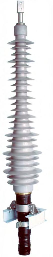
10 Cable accessories Outdoor termination Equipment mount termination HV Power Cable Joint

11 Distribution of electrical stress in Conductor screen power cable 2 V Einsscr. = ODins ODins ln ODcondscr. Insulation screen


12 Cable end in accessory how does it work? High stress at conductor High stress at insulation screen Stress evenly distributed Cable conductor Cable insulation Cable insulation screen Cable conductor Cable insulation Cable conductor Cable insulation Stress cone insulation Stress cone ground electrode Edge of cable insulation screen Cable End without Insulation screen stripped back Cable End with Insulation screen stripped back Cable End inside termination

13 Extruded Cable Conductor Screen Insulation Screen Metallic Sheath Screen Wires Jacket

14 OUTDOOR TERMINATIONS GIS & Oil Immersed TERMINATIONS JOINTS
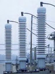
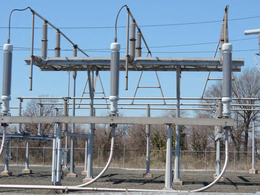
15 Use of outdoor terminations Cable terminations connects power cable to other electrical components: Overhead lines Station buses

16 Structure-mount outdoor terminations in substation Termination


17 Pole mount outdoor terminations on transmission line pole Termination

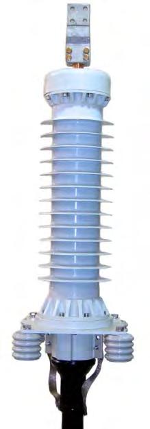
18 Typical design of outdoor termination

19 Distribution of electrical stress in the critical areas Outdoor Termination Deflector radius Interface between stress cone and cable insulation Deflector angle
")
20 Silicone Rubber Stress Cone Insulating Rubber Oil seal Sleeve Conductive Rubber (Deflector)
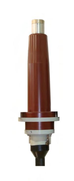
21 Use of equipment mount cable termination GIS cable termination connects the cable to the gas insulated switchgear (GIS) Oil-immersed termination connects the cable to power transformer

22 GIS Housing GIS Termination GIS terminations GIS terminations

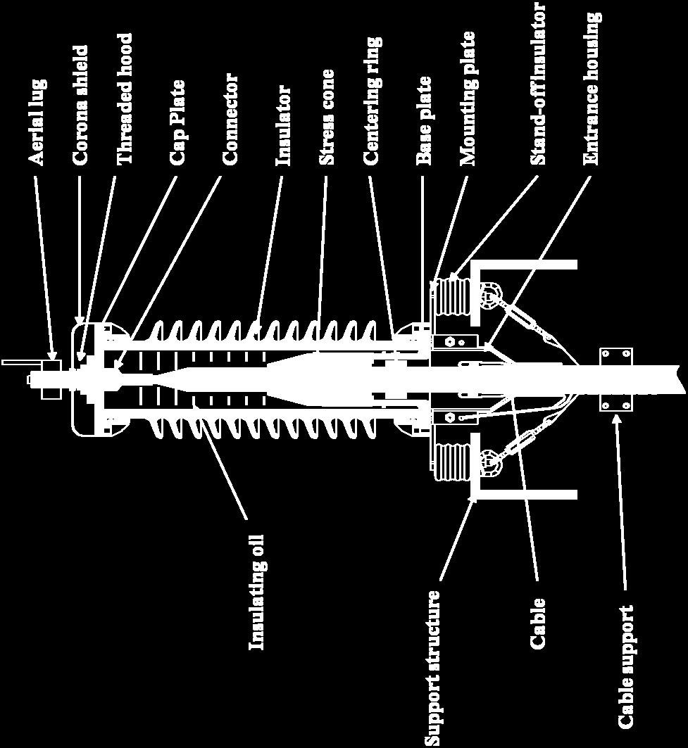
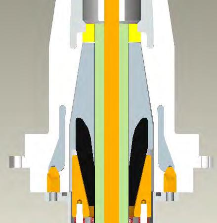
23 Typical design of dry type GIS termination Contact pad Corona shield Connector Epoxy insulator Stress cone GIS interface plate Clamping ring Compression spring assembly Cable Entrance housing Cable support
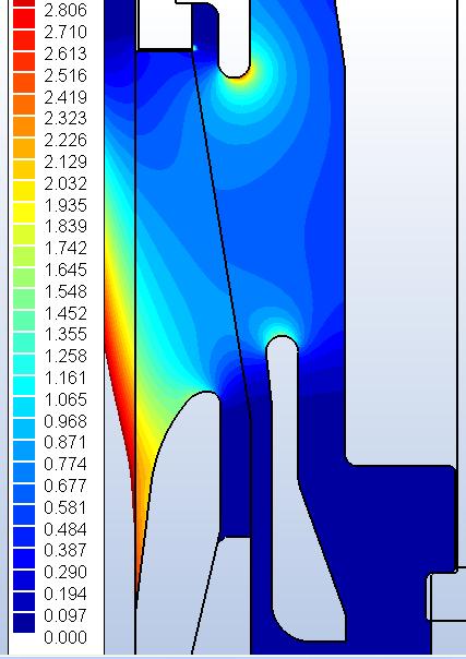
24 Design considerations

25 Per international and domestic standards it is required that terminations and GIS gear are interchangeable regardless of who made them. G&W GIS terminations meet that requirement.

26 Joint Design - General Joint outer screen Shield Break Cable semi-con screen HV electrode Ground electrode (deflector)

27 Electrical stress inside the joint Design - Electrical

28 Design - Electrical Magnitude of electrical stress in the critical areas Corona shield Deflector top Deflector angle
29 Use of Joint in Cable Bonding Cable bonding functions: Limit cable metallic screen voltages Reduce or eliminate the screen losses Maintain a continuous ground path to permit fault-current return and adequate lightning and switching surge protection.
30 Multiple Point Bonding Induced current in screen Load current Cable metallic screen Lower load rating of cable system Zero voltage at both cable ends (no safety hazard)
31 Single Point Bonding Induced Voltage in screen Voltage at open end (In US V Max) Cable length Induced voltage at open cable end (safety hazard) Higher load rating of cable system
32 Cross Bonding use of shield break joints Location of shield-break joints No induced voltage at open cable end (no safety hazard) Higher load rating of cable system


33 Paper Cables PIPE OIL or GAS PAPER CABLES
34 OUTDOOR TERMINATIONS EQUIPMENT TERMINATIONS Straight Joints
35 Stress in paper cables x y g Cable conductor Cable insulation Dc Di Joint insulation Stress cone (L-L profile) Formula for axial component of electrical field at the stress cone g = E x Ln Ln Ln y Dc 2 Di Dc
36 Oil-impregnated paper cable Relevant for connector design Relevant for Stress cone design

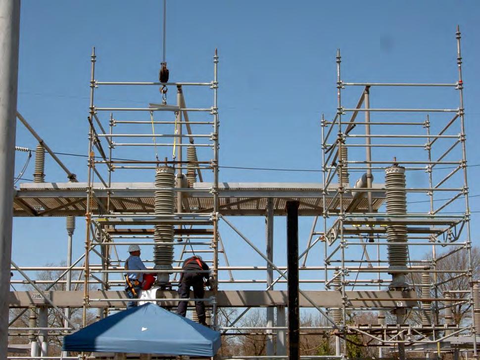
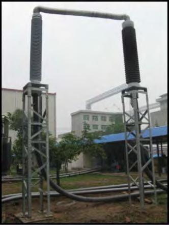
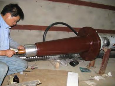
37 Retrofit of the old termination with new one
38
39
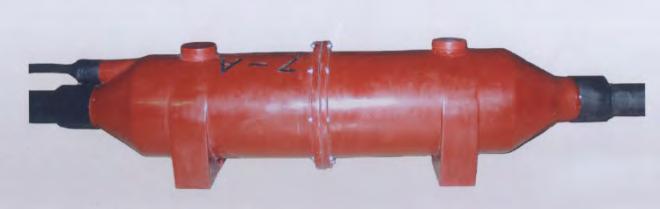
40 HV Transition Joints Definition: Device for connecting HV oilimpregnated paper cable to solid dielectric cable Typical application: To expand existing UG transmission network To replace ailing section of old oilimpregnated paper cable with new extruded cable
41 HV Transition Joints Relatively small usage, expected to grow significantly Up to 161 kv class, many different designs in operation At 230 kv most designs are back-toback Limited use and availability at 345 kv High pressure vs. Low pressure (in regard to insulating fluid at paper cable side)
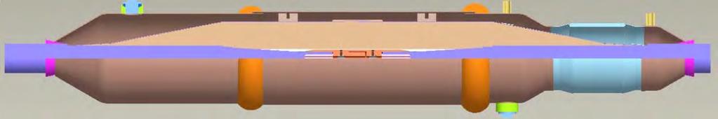
42 Back-to-Back with two Insulators (CIGRE TB 415) Equipment type termination for extruded cable Equipment type termination for paper cable Gas or liquid Housing Extruded cable Paper cable Connector Corona shields
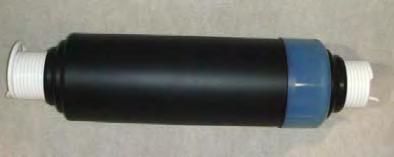
43 Back-to-Back with one Insulator Stress cone Gas or insulating liquid GIS or Transformer type termination Extruded cable Paper cable Conductor Seal Corona shield Connector Housing
44 Composite design Stress cone Epoxy insulator with built-in HV electrode Paper cable stress cone Extruded cable Paper cable Springs Connector Housing Gas or liquid
 Tinned Cu housing Dry-Type Termination Connector clamp Paper cable Insulating")
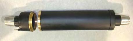
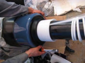
45 Single-core Transition Joint for SCFF Cable Back-to-Back with One Insulator Extruded cable Stainless steel housing Stress cone (paper roll) Tinned Cu housing Dry-Type Termination Connector clamp Paper cable Insulating fluid


46 Stress cone installation with perforated Paper Roll Paper roll (stress cone) Stress cone slope Paper is torn along factory cut perforations

47 Finalizing the stress cone Copper band Copper mesh is applied over the slope

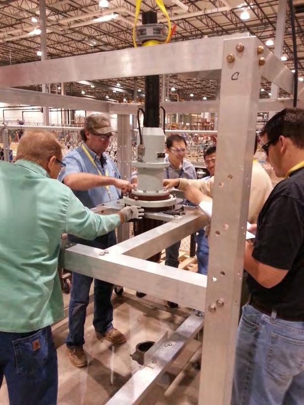
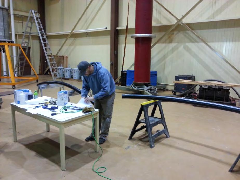
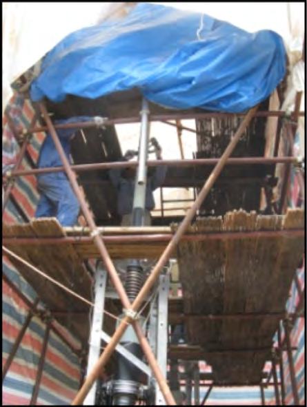
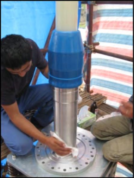
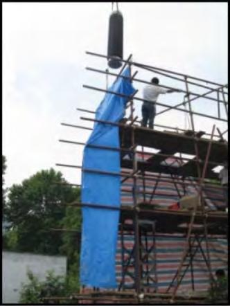
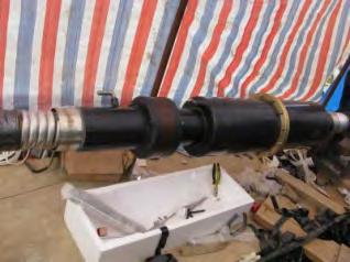
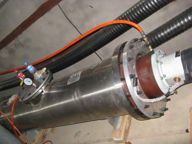
48 Field Installation Final installation step: Oil filling of the single core 138 kv LPOF to XLPE transition joints in the field

49 Three-core Transition Joint Telescoping housing suitable for short manholes Dry-type GIS terminations 3-C Paper cable Oil breach assembly Spider assembly reinforced to prevent TMB Paper roll and crepe paper tape build-up

50 Installation of 3/C Transition Joint Bushing of the drytype termination

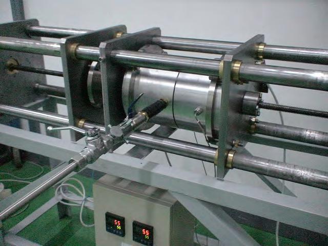
51 Design Tests per IEEE kv HPFF Transition Joint Extruded cable in conduit HPFF transition joint Number of samples: 2 AC voltage: 1min and 24h Impulse voltage Ionization factor Load Cycling Pipe-type cable Accumulator HPFF transition joint Extruded cable
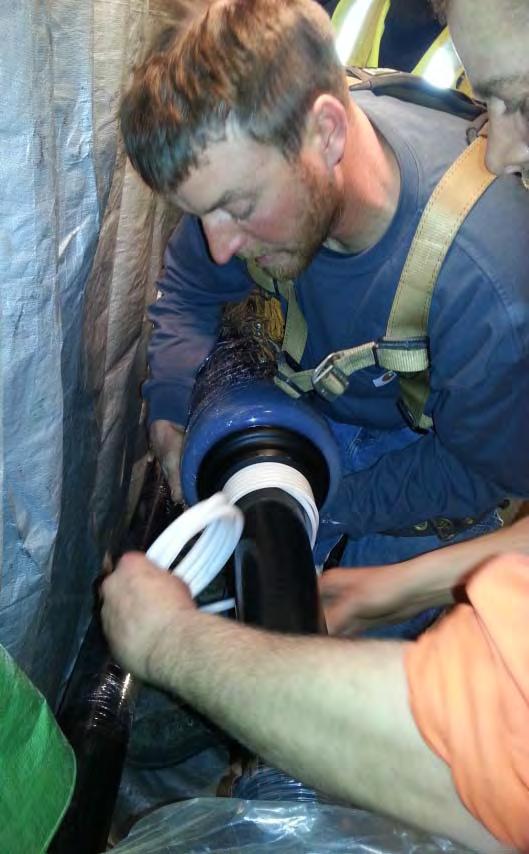

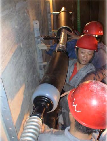
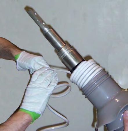
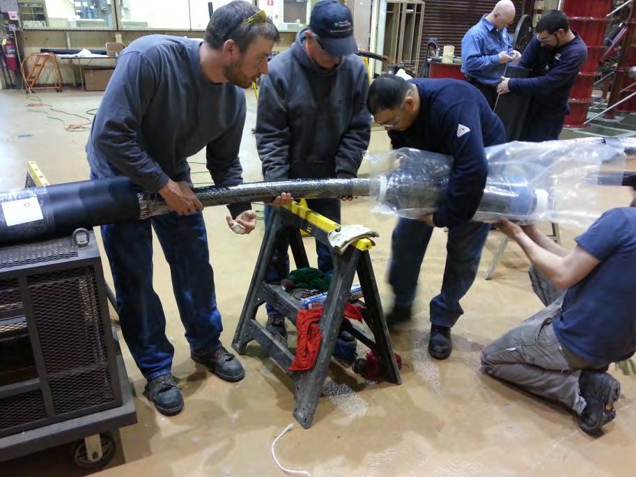
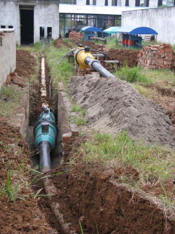
52 Installation of Cable Accessories
53 Excerpt from International study on worldwide usage of HV cable systems (CIGRE TB 177, Section 3 Worldwide Usage of Accessories for HV Extruded Cables, Page 29) The assembly of the accessories is the most vulnerable part of a project involving the manufacture and installation of a new cable circuit.
54

55 Parts Heat shrinkable tubing B/M and installation instructions Joint body expended onto spiral core tube Self-fusing insulating tape Semi-con tape, 25mm wide Semi-con tape, 50 mm wide PVC tape Sand paper #150 to #600 grit Self-fusing Aqua-Seal tape Tinned Cu grounding mesh Connector Hot-melt tape #18AWG Cu wire String solder Gloves
56 Installation Steps 1. Cable preparation / Preparacion del cable 2. Connector crimp / Ponchado del conector 3. Connector tape fill / Encintado con cinta semicontora sobre el conector 4. Shrinking of the joint body / Contraccion del empalme 5. Taping and grounding / Encintado y Aterrizado 6. Outer joint protection / Colocacion de la manga termocontractil y (si es necesario) la cubierta de cobre
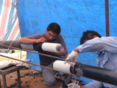
57 Cable preparation Prepare cable ends per installation instructions / Preparacion del cable de acuerdo a instruccines de instalacion

58 Connector crimp Slide the connector onto cable conductor

59 Connector crimp Butt the conductors into the connector

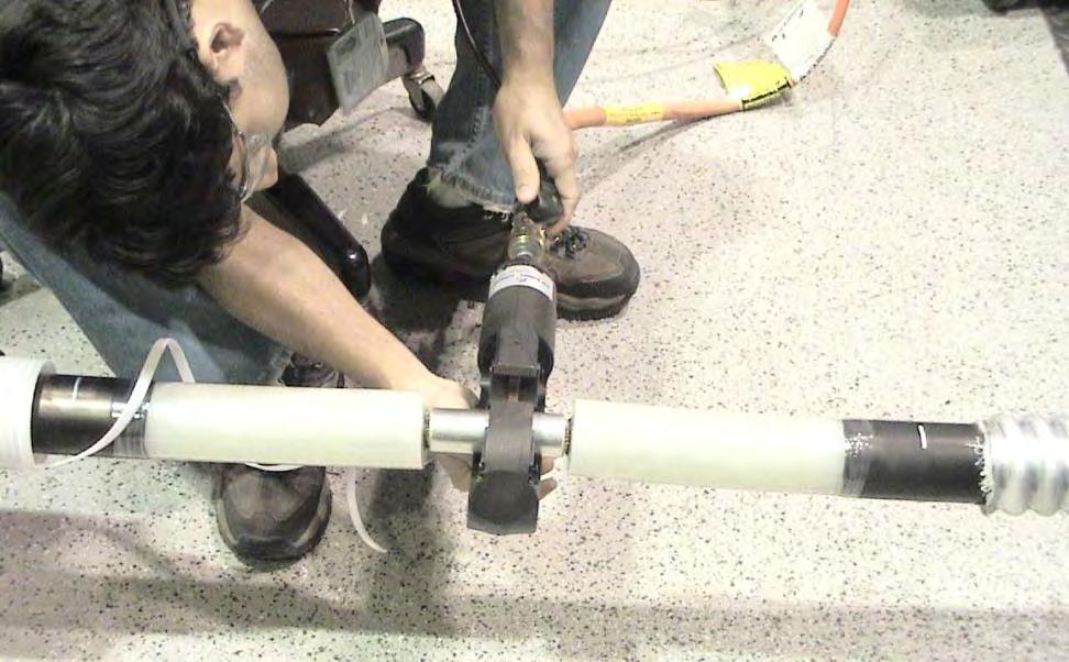
60 Connector crimp

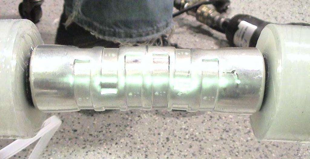
61 Connector crimp


62 Shrinking of the joint body Clean cable insulation and apply grease


63 Shrinking of the joint body Position the joint and start pulling the cord

64 Shrinking of the joint body

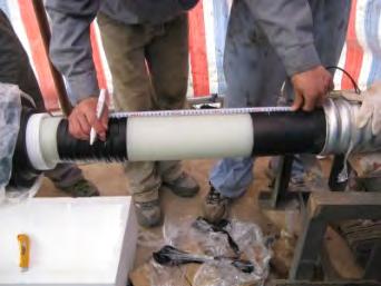
65 Shrinking of the joint body Check the position of the joint relative to the positioning marks


66 Taping and grounding Apply semi-con tape and insulating tapes over the joint per instructions


67 Taping and grounding Apply copper mesh over the semi-con tape and solder to cable metallic sheath
68 Outer joint protection Heat shrink tube Copper housing and / or fiberglass coffin are optional


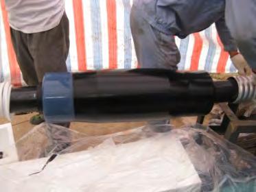
69 Outer joint protection Position heat shrink tube over the joint


70 Outer joint protection Apply heat uniformly to shrink down the tube
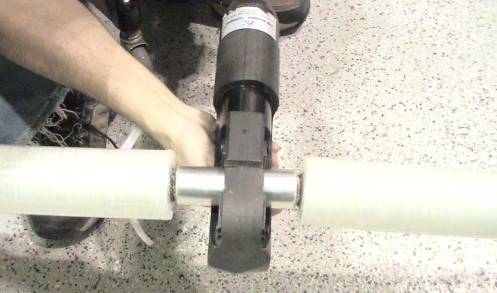
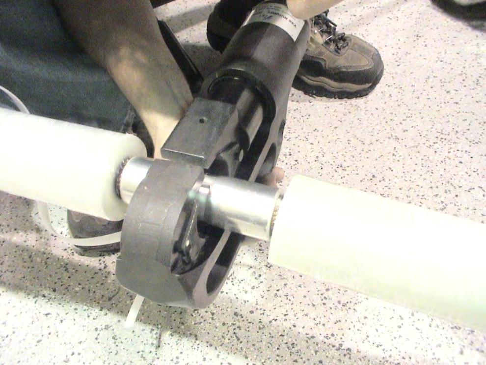
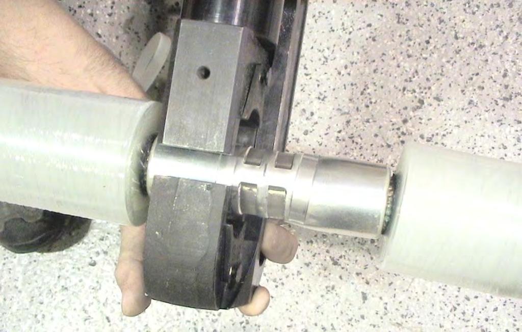
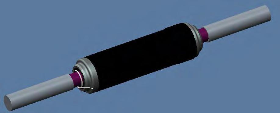
71 Mechanical Shrink Installation Method for Stress Cones and Joints Main drivers: for Extruded Cables Minimizes chances for field errors and damage Reduces required space, installation time and cost
72 Mechanical Shrink Installation Method for Stress Cones and Joints for Extruded Cables Scone sliding.avi GW Mechanical Shrink Accessories-live demonstration.mpg


73 SLIP- ON Cable prep: Accommodates for slip on the parking side, requires rejacketing MECHANICAL SHRINK Typically no need for additional rejacketing


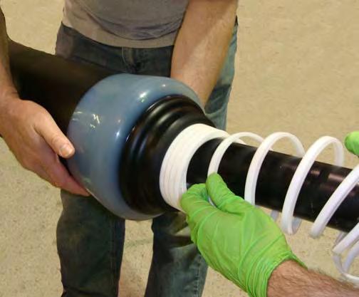
74 SLIP- ON Parking: Joint body is pushed onto the cable; requires special tool and extra time and space MECHANICAL SHRINK Joint body is parked onto the cable, no tool required


75 SLIP- ON Final positioning: Joint body is pushed back the cable; requires special tool, creates mechanical stress MECHANICAL SHRINK Joint body is positioned and cord is removed, no tool is required
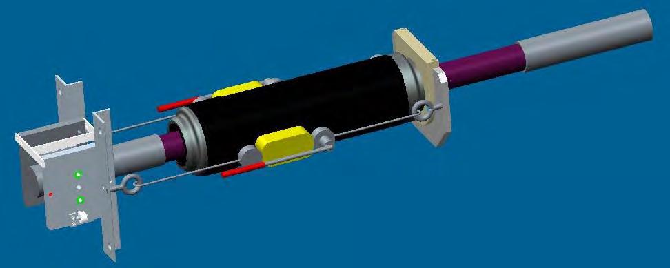
76 SLIP- ON MECHANICAL SHRINK
77 Process and Tooling design Molding process Parameters Flow rate Temperature Pressure Molding process Variations Material (properties, quality issues) Operators (degree of process automation, skill set, training) Equipment variations Need to build process robust enough to compensate for the variations
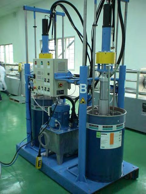
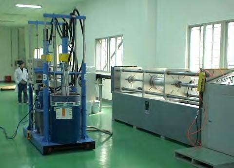
78
79
80 Comparison of Different Specifications for Cable Accessories and Cable Systems
81 Cable, Accessory & System Standards Governing Body ICEA IEC IEC AEIC IEEE IEEE Standard ICEA S Standard for Extruded Insulation Power Cables Rated Above 46 through 345 kv IEC Power cables with extruded insulation and their accessories for rated voltages above 30 kv (U m = 36 kv) up to 150 kv (U m = 170 kv) - Test methods and requirements IEC Power cables with extruded insulation and their accessories for rated voltages above 150 kv (U m = 170 kv) up to 500 kv (U m = 550 kv) Test methods and requirements AEIC CS9 Specification for Extruded Insulation Power Cables and Their Accessories Rated Above 46kV through 345 kv AC IEEE 48 IEEE Standard for Test Procedures and Requirements for Alternating-Current Cable Terminations Used on Shielded Cables Having Laminated Insulation Rated 2.5 kv through 765 kv or Extruded Insulation Rated 2.5 kv through 500 kv IEEE 404 IEEE Standard for Extruded and Laminated Dielectric Shielded Cable Joints Rated 2.5 kv to 500 kv Current Edition / (2013)
82 Tests Requirements for Individual Components IEC 60840, Section for cables IEC 60840, Section for cable accessories ICEA S for cables IEEE 48 (US accessory makers and users) for terminations IEEE 404 (US accessory makers and users) for Joints Tests Requirements for System IEC (International) section for cable systems IEC (International) section for cable systems AEIC CS9 (US utilities) for cable systems
83 Definitions Design Test Used in IEEE 48 and 404 to describe test sequences to qualify termination or joint for use on any cable with same or lower size / stress level. Equivalent to Type tests in IEC. Type Test Used in IEC standards for a component test (cable, termination or joint) or cable system test in order to qualify component or a system. Qualification Test on Complete Cable System Used in AEIC specification to describe a Type Test (as described in IEC). Prequalification Test Used in IEC and AEIC standards for a long term cable system test including different installation conditions (flexible and rigid, direct burial, tunnel and conduit) to demonstrate performance of a system.
84 Industry Standards New Developments in IEEE IEEE 48 Standard for Test Procedures and Requirements for AC Cable Terminations Used on Shielded Cables Having Laminated Insulation Rated 2.5 kv through 765 kv or Extruded Insulation Rated 2.5 kv through 500 kv Rev 2009 IEEE 404 Standard for Extruded and Laminated Dielectric Shielded Cable Joints Rated 2.5 kv to 500 kv Rev 2012 IEEE 48 and 404 will be combined: IEEE 48/404 for Distribution (up to 46 kv) IEEE 48/404 for Transmission (69 kv and up)
85 Industry Standards New Developments in IEEE New split combines accessories, splits voltage levels: Combine Terminations and Joints into one document Split Distribution and Transmission Two new IEEE standards Two new DGs were approved; First ICC Fall meeting 2015

86 Design and Type tests
 Type test per ICEA (cables) Remaining type El. tests per IEEE 48 El.")

87 LOOP #1 Initial tests per IEEE 48 (terminations) Very tough requirements, up to 4Uo LOOP #2 Type tests per IEC (system test) Type tests per AEIC (system test) Type test per ICEA (cables) Remaining type El. tests per IEEE 48 El. Type test per IEEE 404 (joints) - Outdoor with composite insulator - Outdoor with porcelain insulator - Two Oil filled GIS - Two Dry Type GIS - Two Cable types The same loop plus four joints: Two without shield break in water Two with shield break in air Total ten accessories, two cable types

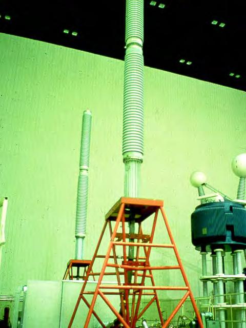
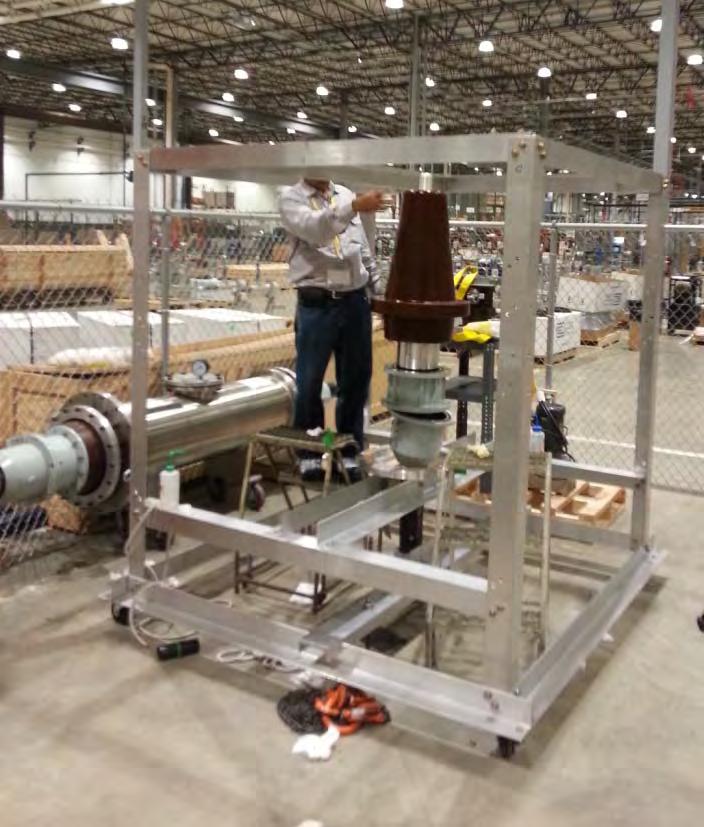
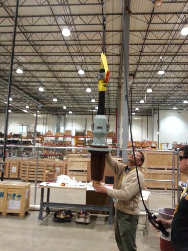
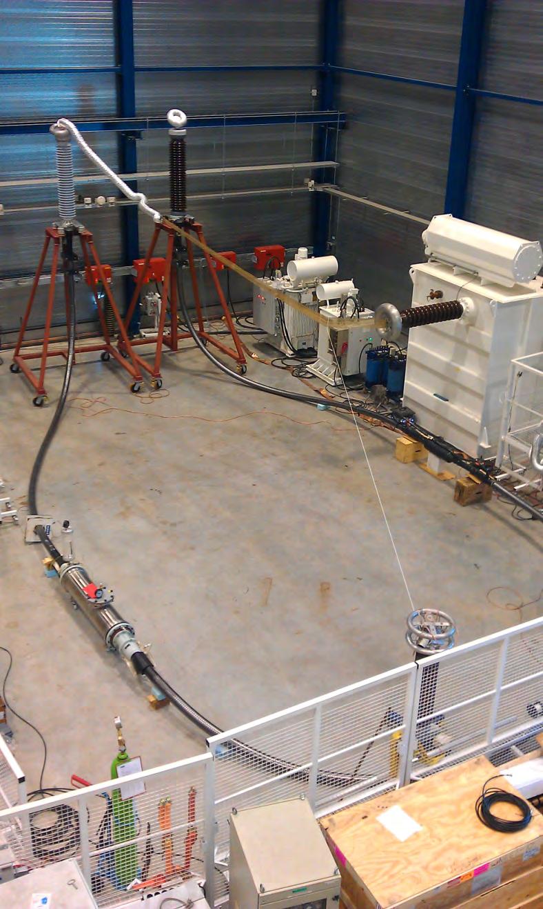
88 IEEE 48 and 404 Test Loop

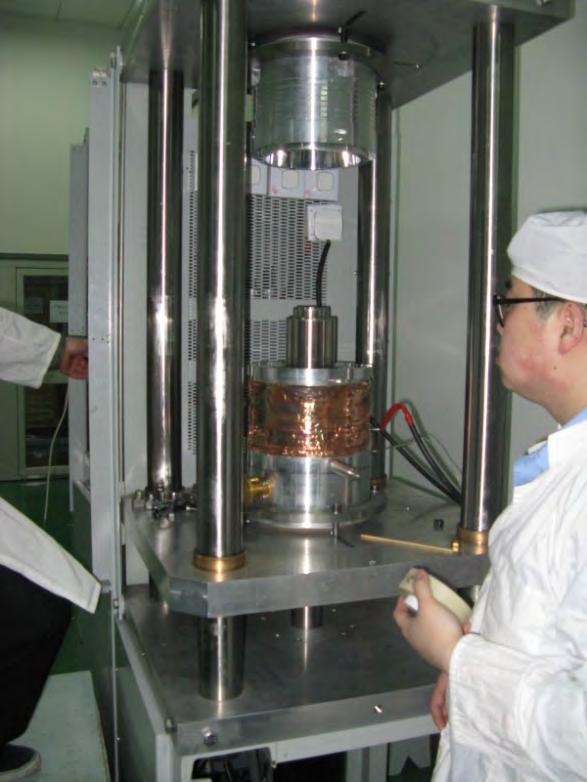
89 G&W HV Lab

90 G&W HV Lab

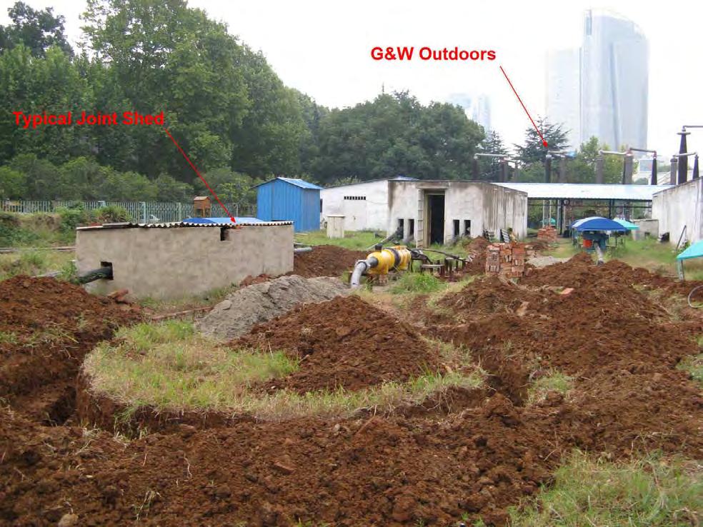
91 PQ test field


92
93
94 Conclusions HV Cable Accessories Terminations and Joints are the critical link in any modern cable system There are many different designs that can work with any modern cable designs that follow latest cable standards Oil-filled cables (OF) are still dominant technology that has been field proven over the years Transition joints are becoming increasingly important as new solid dielectric cables are being utilized Installation of is tying together cables and accessories and highly qualified jointers are a must! New developments in standardization are critical for further successful applications of cables and their accessories
TRANSMISSION ENGINEERING STANDARD TES-P , Rev. 0 TABLE OF CONTENTS 1.0 SCOPE 2.0 CABLES SPLICES
 1.0 SCOPE TABLE OF CONTENTS 2.0 CABLES SPLICES 2.1 Definitions 2.2 Scope of Specifications and Drawings 2.3 General Requirements 2.4 Routing Cables 2.5 Connectors 2.6 Conductor Connections 2.7 Heat Shrinkable
TERMINATIONS AND JOINTS FOR XLPE-INSULATED kv MEDIUM VOLTAGE CABLES
 Accessories TERMINATIONS AND JOINTS FOR XLPE-INSULATED 12 36 kv MEDIUM VOLTAGE CABLES Cable Systems, Cables and Accessories Test values for terminations 1) Testing to DIN VDE 0278-629-1 (Testing methods
CLP s first 400kV XLPE cable application
 CLP s first 400kV XLPE cable application Chris Cheung CLP Power Hong Kong Limited 9 October 2017 Information Classification : PROPRIETARY Information Classification : PROPRIETARY Project Requirement Due
640 kv XLPE HVDC cable system
 640 kv XLPE HVDC cable system World s most powerful extruded cable system enables utilization of renewable energy resources nkt.com Demand for higher voltages NKT s new 640 kv XLPE DC cable system is the
Student Services & Classroom Addition
 SECTION 260513 - MEDIUM-VOLTAGE CABLES PART 1 - GENERAL 1.1 SUMMARY A. Section includes cables and related cable splices, terminations, and accessories for mediumvoltage (2001 to 35,000 V) electrical distribution
Revision of Qualification Procedures for High Voltage and Extra High Voltage AC Extruded Underground Cable Systems
 Revision of Qualification Procedures for High Voltage and Extra High Voltage AC Extruded Underground Cable Systems Tutorial vor the ICC Educational Session on November 11 2009 in Scottsdale, AZ by Wim
HVDC cable accessories
 ^=r SVENSKA KRAFTNÄT SWEDISH NATIONAL GRID UNIT, BUSINESS AREA OUR REFERENCE TR14-02-5E DATE 2018-09-21 CONSULTATIÖNS NT, NB TECHNICAL GUIDELINE EDITION 1 APPROVED TD HVDC cable accessories This technical
SECTION MEDIUM VOLTAGE CABLE INSTALLATION. 1. Section Underground Ducts and Manholes.
 SECTION 33 71 49.23 MEDIUM VOLTAGE CABLE INSTALLATION PART 1 GENERAL 1.1 SCOPE A. Work included in this Section: Medium Voltage Cable (4 kv and 12 kv) Installation and Termination. Removal and return of
Trends and Challenges of HV Cable Systems
 Trends and Challenges of HV Cable Systems Bruno Arnold Electrical Engineer FH Global Sales Far East, Latin America and India Pfisterer Business Unit PTS Cable Trends and Challenges of HV Cable Systems
LEGEND POWER SYSTEMS
 S HEAT SHRINK JOINT 11kV 3 CORE Armoured XLPE/EPR Copper Wire screens STRAIGHT JOINT LEGEND POWER SYSTEMS Date 11 November 2014 Instruction Number PJJ006-14C PJJ006-14C Page 1 of 10 HEAT SHRINKABLE JOINT
ECONOMICAL 36 kv CABLE SYSTEM FOR THE BELGIAN NETWORK
 ECONOMICAL 36 kv CABLE SYSTEM FOR THE BELGIAN NETWORK J. Becker NEXANS BENELUX S.A. F. Musique ELECTRABEL S.A. ABSTRACT In order to tackle the deregulated market with confidence and in a realistic way,
640 kv extruded HVDC cable system
 640 kv extruded HVDC cable system World s most powerful extruded cable system Pehr Bergelin, Marc Jeroense, Tobias Quist, Hans Rapp NKT Summary In this paper, NKT s new 640 kv extruded DC cable system
Automatic Connector MHV Connectors MHV Introduction MHV series connectors Contents Polarized mating interfaces Anti-Rock mating interfaces
 Automatic s 2004 Automatic. All rights reserved. pdf 1.0 3-18-04 Contents Specifications........................... 2 Straight Cable Plugs...................... 3 Right Angle Cable Plugs...................
Cable installation guidelines
 The Quality Connection Cable installation guidelines Business Unit Industrial Projects 2 Cable installation guidelines www.leoni-industrial-projects.com GENERAL Installation methods Many different methods
3M Cold Shrink QS-III Silicone Rubber Splice Kit 5488A-TOW/WOT
 3M Cold Shrink QS-III Silicone Rubber Splice Kit 5488A-TOW/WOT For Tape Over Wire (TOW) and Wire-Over-Tape (WOT) Shielded Cable For 250 2000 kcmil cable with 650-mil primary insulation thickness Instructions
POLICY & APPLICATION GUIDE FOR 11kV POLYMERIC CABLES
 1. SCOPE This document provides information and guidance on the application of polymeric cables on the SPEN 11kV network. Throughout this document, references to 11kV shall by inference also relate to
3M Cold Shrink QS-III Splice Kit 5467A(S)-WF
-WF") 3M Cold Shrink QS-III Splice Kit 5467A(S)-WF for Jacketed Concentric Neutral (JCN) Cable Instructions IEEE Std. 404 35 kv Class 250 kv BIL F CAUTION Working around energized systems may cause serious injury
3M Cold Shrink QS-III Splice Kit 5467A(S)-WF for Jacketed Concentric Neutral (JCN) Cable Instructions IEEE Std. 404 35 kv Class 250 kv BIL F CAUTION Working around energized systems may cause serious injury
3M Cold Shrink Splice Kit QS-III 5416A
 3M Cold Shrink Splice Kit QS-III 5416A for Jacketed Concentric Neutral (JCN) and Concentric Neutral Cable Instructions IEEE Std. 404 15 kv Class 150 kv BIL CAUTION Working around energized systems may
STRAIGHT TWO WAY JOINT3/C, PAPER INSULATED, SHIELDED, LEAD COVERED CABLE. Revised: October 10, 2008 Revised By: SGL Approved By: RHS SPLICES
 STRAIGHT TWO WAY JOINT3/C, PAPER INSULATED, SHIELDED, LEAD COVERED CABLE I. INSTALLATION INSTRUCTIONS I.1. PRECAUTIONS: I.1.1. Expansion bends must be made in the cables to allow for cable movement while
Instructions. Cable with Armor F CAUTION. October Rev A
 3M Single Conductor Accessory Breakout Kits (BOK's) for use with 3M Cable Accessories (Terminations, T-Bodies and Push-On Elbows) For Use With Single Conductor Accessories On Three-Core Conductor Cables
3 Cold Shrink Products
 3 Cold Shrink Products Low Voltage Splices 0-600V (1000V rated) 279 Cold Shrink Splices (0-1000V) 279 Cold Splicing Products 279 Resin Splices 0-600V (1000V rated) 281 Resin 284 3M 8420 and 8430 Series
DOME OPTIC SPLICE CLOSURE
 FIBER OPTIC SPIICE CLOSURE GJS-JKDH1001-120 BOX DIMENSION: W=140mm H=340mm Weight = 1.80 kgs Outer Internal structure Fuse fiber disc Type sealing ring Plastic hoop base Pole Mount Pole Mount 1 1. product
HN Connectors. Automatic Connector. Introduction. Contents. 631/ FAX 631/
 Connectors Introduction 2004 Automatic Connector. All rights reserved. pdf 1.0 4-13-04 Contents Specifications........................... 2 Straight Cable Plugs...................... 3 Right Angle Cable
3M Cold Shrink QS4 Integrated Splice Kit QS4-15JCN
 3M Cold Shrink QS4 Integrated Splice Kit QS4-15JCN-500-1000 for Jacketed Concentric Neutral (JCN) and Flat Strap Neutral Cable Instructions IEEE Std. 404 15 kv Class 150 kv BIL F CAUTION Working around
HARTING Ethernet cabling cables and connectors, 4 wire
 Industrial Cat. 5e Standard cable, 4-wire Type A for permanent installation or to build-up PROFINET system cables PVC X 8 wire X Cat. 5e X Cat. 6 Cat. 6 A Cat. 7 Cable structure Core structure Wire insulation
3M Cold Shrink QS4 Integrated Splice Kit QS4-35TS
 3M Cold Shrink QS4 Integrated Splice Kit QS4-35TS-350-1000 for Tape Shield, Wire Shield, UniShield, and Longitudinally Corrugated (LC) Cable Instructions IEEE Std. 404 35 kv Class 250 kv BIL F CAUTION
Low Voltage Splices, 1000 V or less
 For installations from 120 V to 1 kv, 3M offers several low voltage splice options, including 3M-developed cold shrink technology, heat shrink, resin and tape. 3M Low Splices are reliable in buried, overhead,
VITALink Taped Splice Straight Through Crimp
 A Marmon Wire & Cable Berkshire Hathaway Company VITALink Taped Splice Straight Through Crimp 2 Hour Fire-Rated Splice VITALink MC Cables, UL FHIT 120 Installation Instructions Description The VITALink
Public Works Division Lighting District Fiber Optic Specifications April 2009
 Public Works Division Lighting District Fiber Optic Specifications April 2009 7000 Florida Street Punta Gorda, Florida 33950 Tele: 941.575.3600 Fax : 941.637.9265 www.charlottecountyfl.com/publicworks
3M Cold Shrink QS4 Integrated Splice Kit QS4-15JCN-4/0-500
 3M Cold Shrink QS4 Integrated Splice Kit QS4-15JCN-4/0-500 for Jacketed Concentric Neutral (JCN) and Flat Strap Neutral Cable Instructions IEEE Std. 404 15 kv Class 150 kv BIL CAUTION Working around energized
220KV EHV NETWORK AT RELIANCE JAMNAGAR REFINERY COMPLEX
 220KV EHV NETWORK AT RELIANCE JAMNAGAR REFINERY COMPLEX JAMNAGAR 220KV CABLE NETWORK: 2 2. DESIGN 2A. NETWORK: 220 KV NETWORK DESIGN IS DESIGNED WITH 100% REDUNDANCY FROM 220 KV BUS TO LOAD. THIS IS ACHIEVED
Amphenol. Amphenol-Tuchel Electronics GmbH. C 112 Series M12 - Connectors
 Amphenol Amphenol-Tuchel Electronics GmbH C 112 Series M12 - Connectors We connect con The company Amphenol-Tuchel Electronics is a worldwide leader in electrical connectors and contacting devices. Our
HSK Mine and Portable Cable Splice
 8096-4-HSK Mine and Portable Cable Splice Instructions 5 and 8 kv rated cables; Type SHD-GC Size 2/0 4/0 (connector max. length 2 1/2") 8096-4-HSK Mine and Portable Cable Splice 78-8119-6296-4-A 1 1.0
Aging test: integrated vs. non-integrated splices shield continuity systems.
 Aging test: integrated vs. non-integrated splices shield continuity systems. George Fofeldea Power Engineer, 3M Canada November 2018 Abstract To maximize long-term splice performance, the implications
PEM1126ENG ENGLISH STPKR. TERMINATION KIT FOR PAPER CABLE WITH LEAD SHEATH 1 kv INSTALLATION INSTRUCTION
 INSTALLATION INSTRUCTION PEM1126ENG 2010-05 TERMINATION KIT FOR PAPER CABLE WITH LEAD SHEATH 1 kv ENGLISH 2/6 PEM1126ENG 2010-05 GENERAL INFORMATION - Check that the kit is suitable for the cable type.
3M Cold Shrink Splice Kit QS-III 5514A
 3M Cold Shrink Splice Kit QS-III 5514A for UniShield, Wire Shielded, Longitudinally Corrugated (LC), and Tape Shielded (Ribbon Shielded) Cable or Transitions to Concentric Neutral (CN)/Jacketed Concentric
Stainless Steel SMA Connectors Product Catalog
 Stainless Steel SMA Connectors Product Catalog Connectivity...for Stainless Steel SMA Connectors Connectivity...for Johnson Stainless Steel SMA Connectors meet or exceed the performance requirements of
High Temperature Operation of Extruded Distribution Cable Systems. White Paper
 High Temperature Operation of Extruded Distribution Cable Systems White Paper October 2018 NOTICE The information contained herein is, to our knowledge, accurate and reliable at the date of publication.
3M Sensored Termination (15 kv) QX-T15I-vi1-E
 QX-T15I-vi1-E") 3M Sensored Termination () QX-T15I-vi1-E Data Sheet May 2016 Kit Contents: Each kit contains sufficient quantities of the following materials to make three single-phase terminations. 31" (REF) One piece
3M Sensored Termination () QX-T15I-vi1-E Data Sheet May 2016 Kit Contents: Each kit contains sufficient quantities of the following materials to make three single-phase terminations. 31" (REF) One piece
NC-1000 INSTALLATION MANUAL NC-1000 FIBRE OPTIC CROSS-CONNECTION SYSTEM
 NC-1000 INSTALLATION MANUAL NC-1000 FIBRE OPTIC CROSS-CONNECTION SYSTEM Content 1. General 5 2. The products of NC-1000 system 6 3. Mounting of the frame 8 4. Earthing of the frame 8 NC-1000 FIBRE OPTIC
2179-CD Series Fiber Optic Splice Closure. Installation Instructions
 2179-CD Series Fiber Optic Splice Closure Installation Instructions 1.0 Product Introduction The new 3M TM 2179-CD Series Fiber Optic Splice Closure can be used in buried, underground, aerial, and pedestal
UNDERGROUND CONSTRUCTION MANUAL MATERIAL DATA
 UNDERGROUND CONSTRUCTION MANUAL Back to MAIN INDEX Go to SECTION INDEX CONSTRUCTION DESCRIPTION DWG CONSTRUCTION DESCRIPTION DWG LV cable details 5108 HV cable details 5109 Insect protected LV cable details
3M Cold Shrink Splice Kit QS-III 5515A
 3M Cold Shrink Splice Kit QS-III 5515A for UniShield, Wire Shielded, Longitudinally Corrugated (LC), and Tape Shielded (Ribbon Shielded) Cable or Transitions to Concentric Neutral (CN)/Jacketed Concentric
2016 Cable Splicing Courses
 206 Cable Splicing Courses The electrical training ALLIANCE will be offering medium voltage (2,00-35,000 volts) cable splicing classes at several different locations in 206. Module I, of the cable splicing
Cold Shrink Straight Joint
 Cold Shrink Straight Joint 3M QS2000E 22 kv Single Core Straight Joint Instruction Sheet All dimensions shown are in mm unless otherwise stated Kits contains components for one single core cable -2-2*
Instrukcja montażu. FLEX LED Neon Instalacja
 FLEX LED Neon Instalacja Instrukcja montażu Polned Sp. z o.o. ul. Falencka 7 PL05-090 Janki Tel. +48 22 4903434 +48 22 4903243 www.polned.pl info@polned.pl. Product Checking: 1) Unpack and carefully examine
Non Magnetic Connectors
 Non Magnetic Connectors Johnson Components builds coaxial connectors using innovative materials and design to provide Mil Spec Performance at a commercial price. Now we offer our Non Magnetic Connectors
TFT-150R-G. Tape Shield Cable (page 2) Suggested Installation Equipment (not supplied with kit) Wire Shield Cable (page 7)
 Suggested Installation Equipment (not supplied with kit) Wire Shield Cable (page 7)") TFT-150R-G 5-15kV Cold Applied Indoor (5-8kV Indoor and Outdoor) Termination for Copper Tape, Wire Shield, Lead Sheath, and UniShield Cable Suggested Installation Equipment (not supplied with kit) Cable
TFT-150R-G 5-15kV Cold Applied Indoor (5-8kV Indoor and Outdoor) Termination for Copper Tape, Wire Shield, Lead Sheath, and UniShield Cable Suggested Installation Equipment (not supplied with kit) Cable
Quick Term III. 3M Cold Shrink 3 Core Indoor Termination. 3.3 kv mm 2
 Quick Term III 3M Cold Shrink 3 Core Indoor Termination Instruction Sheet All dimensions shown are mm unless otherwise stated Kit Contents 3 QT-III Termination Assembly 1 Cold Shrink Breakout Boot 3 Phase
Connecting cables NEBS, for sensors
 Connecting cables NEBS, for sensors Connecting cables NEBS, for sensors Product range overview Function Version Type code Connection technology (Electrical connection 2) Connecting cable Cable characteristic
3M Distribution Box (DDB)
") 3M Distribution Box (DDB) Merged Copper and Fiber Pole/Post Mount Enclosure Installation Instructions November 2015 78-0015-2736-1-A 2 November 2015 78-0015-2736-1-A Contents 1.0 General 2.0 Enclosure
3M Distribution Box (DDB) Merged Copper and Fiber Pole/Post Mount Enclosure Installation Instructions November 2015 78-0015-2736-1-A 2 November 2015 78-0015-2736-1-A Contents 1.0 General 2.0 Enclosure
Power and Control T YPE BY RAVI GANATR November/December IAEI NEWS
 Power and Control 26 1999 November/December IAEI NEWS T YPE BY RAVI GANATR This article discusses how the requirements in both the installation code and the product standard are utilized to manufacture
3M Cold Shrink QS4 Integrated Splice Kit QS4-15JCN-2-4/0
 3M Cold Shrink QS4 Integrated Splice Kit QS4-15JCN-2-4/0 for Jacketed Concentric Neutral (JCN) and Flat Strap Neutral Cable Instructions IEEE Std. 404 15 kv Class 150 kv BIL F CAUTION Working around energized
National Wire and Cable and National Cable Molding Headquarters Los Angeles California
 National Wire and Cable and National Cable Molding Headquarters Los Angeles California CAPABILITIES Medical Business Machines Communications Equipment Computer Equipment Audio Systems General Instrumentation
2178-L/S Series Fiber Optic Splice Case with Gasket
 2178-L/S Series Fiber Optic Splice Case with Gasket Instructions for: 2178-S Splice Case 2178-LS Splice Case 2178-LL Splice Case 2181-LS Cable Addition Kit May 1997 34-7041-9949-5-A 1 Table of Contents
TRANSMISSION ENGINEERING STANDARD TES-P , Rev. 0 TABLE OF CONTENTS 1.0 PURPOSE 2.0 SCOPE 3.0 CODES, STANDARDS AND REFERENCES
 TABLE OF CONTENTS 1.0 PURPOSE 2.0 SCOPE 3.0 CODES, STANDARDS AND REFERENCES 4.0 ORDER OF PRECEDENCE 5.0 SYSTEM PARAMETERS 5.1 Frequency 5.2 System Voltage 5.3 Short Circuit Rating 5.4 Insulation Levels
Instrumentation Cables
 Instrumentation Cables 9 KEWBERG manufactures and supplies a wide range of Instrumentation cables, which are made using superior raw materials. These are extensively used in data acquisition systems, process
System 500. Non-fire-rated, mineral insulated copper sheathed wiring cable
 Non-fire-rated, mineral insulated copper sheathed wiring cable For retrofitting feeders in buildings and for ease of installation in tight spaces and difficult runs Cable construction Solid copper conductors
Cable Installation Tips
 Cable Installation Tips Campus Network Design & Operations Workshop These materials are licensed under the Creative Commons Attribution-NonCommercial 4.0 International license (http://creativecommons.org/licenses/by-nc/4.0/)
Small Circular Connector. JN1W / JN2W Series
 COMPONENTS PRODUCT INFORMATION RoHS Compliant NEW Small Circular Connector / Series CONNECTOR MB-0178-5 December 2012 Angle Plug Cable Connecting Straight Plug Wall Mount Cable Connecting Waterproof Cap
EXPlora. Introduction
 Introduction EXPlora The EXPlora range is most suited to manufacturers of ancillary electrical equipment such as motors, pumps, lighting equipment, process and control gear for use in factories and plant
ENERGY /// TRICKS OF THE TRADE TRICKS OF THE TRADE
 ENERGY /// TRICKS OF THE TRADE TRICKS OF THE TRADE Raychem is a world leading brand in power cable accessories technology. We pioneered heat-shrinkable terminations in the 1960 s, joints in the 1970 s
Customer-Owned Outside Plant
 Customer Premises Products (Enterprise) 3 Customer-Owned Outside Plant Fiber Optic Splice Case 2178 Series and Accessories 372 Fiber Optic Dome Splice Closure FD Series 376 Fibrlok II Universal Optical
Fiberglass - Technical Data
 - Technical Data Cable Tray Thermal Contraction and Expansion X : Denotes hold-down clamp (anchor) at support. _ : Denotes expansion guide clamp at support. It is important that thermal contraction and
Flygt Submersible Motor Cables
 Flygt Submersible Motor Cables This brochure contains an overview of the Flygt motor cable assortment. The cables are especially designed for submersible use and made of carefully selected materials. The
COMMON WORK RESULTS FOR INTEGRATED AUTOMATION DESIGN AND CONSTRUCTION STANDARD
 PART 1: GENERAL 1.01 Purpose: A. This standard is intended to provide useful information to the Professional Service Provider (PSP) to establish a basis of design. The responsibility of the engineer is
Identification - electrical services
 Identification - electrical services Aesthetic All live phase cable sheathing to be brown coloured and neutral phase cable sheathing to be blue coloured, all labelled L1, L2, L3 & N respectively in accordance
An introduction to Kabeldon cable accessories kv
 An introduction to Kabeldon cable accessories 1-420 kv 2009, Edition 1 Safe junctions for reliable cable networks Kabeldon cable accessories, safety by simplicity Making light work Modern society depends
PEM1124ENG ENGLISH. STK TERMINATION KIT FOR PLASTIC CABLE WITHOUT ARMOURING 1 kv STKR TERMINATION KIT FOR PLASTIC CABLE WITH ARMOURING 1 kv
 INSTALLATION INSTRUCTION PEM1124ENG 2010-05 STK TERMINATION KIT FOR PLASTIC CABLE WITHOUT ARMOURING 1 kv STKR TERMINATION KIT FOR PLASTIC CABLE WITH ARMOURING 1 kv ENGLISH 4 CORE 3+1 CORE 2/8 PEM1124ENG
SPECIFICATION FIBER OPTIC SPLICE CLOSURE. Spec No : VSS-1007-BS403A-04A/SD. VSS-0107-BS403A-04A/SD R & D Center Manufacturing Division
 SPECIFICATION FIBER OPTIC SPLICE CLOSURE Model Spec. No. Distribution Depts. VSOF-BS403A VSS-0107-BS403A-04A/SD R & D Center Manufacturing Division Sales Division Management Division Revision 10. 07 (Rev.4)
3M Cold Shrink QS4 Integrated Splice Kit QS4-15SP-2-4/0
 3M Cold Shrink QS4 Integrated Splice Kit QS4-15SP-2-4/0 for Jacketed Concentric Neutral (JCN), Flat Strap, Tape Shield and Longitudinally Corrugated (LC) Cable Instructions IEEE Std. 404 15 kv Class 150
EE028: Practical High Voltage Cable Jointing and Termination
 EE028: Practical High Voltage Cable Jointing and Termination EE028 Rev.001 CMCT COURSE OUTLINE Page 1 of 5 Training Description: The range of voltage and capacity of power transmitted through cables is
SMA One Piece Semi-Rigid Connectors
 SMA One Piece Semi-Rigid Connectors The Johnson captivated solderless contact connectors for semi-rigid cable provide a unique solution for high frequency cable assemblers. As compared to standard solder-on
SPECIAL SPECIFICATION 6559 Telecommunication Cable
 2004 Specifications CSJ 0015-09-147, etc. SPECIAL SPECIFICATION 6559 Telecommunication Cable 1. Description. This specification governs the materials, installation, termination, splicing, testing, training,
Connectivity accessories by Nestor Cables
 Connectivity accessories by Nestor Cables NesCon product family includes essential installation and connection accessories for fibre optic networks, from ODFs to joint closures and terminations. www.nestorcables.com
SECTION 7 -- CROSS-CONNECT SYSTEMS
 DETAIL ENGINEERING REQUIREMENTS AT&T March, 2016 Section 7, ATT-TP-76400 Revised NA SECTION 7 -- CROSS-CONNECT SYSTEMS CONTENTS PAGE 1. GENERAL... 7-2 1.1. Introduction... 7-2 1.2. Cable Holes... 7-2 1.3.
Panel-Mounted Thermostat
 Data Sheet 602026 Page 1/7 Panel-Mounted Thermostat EM Series Special features Safety temperature monitor STW (STB) Safety temperature limiter STB Tested according to DIN EN 14597 and PED 2014/68/EU Brief
ELECTRICAL SAFETY INSPECTION REPORT. MTM Garments Ltd.
 ELECTRICAL SAFETY INSPECTION REPORT MTM Garments Ltd. 15934/16004, Chanpara, Medical Road, Uttarkhan, Dhaka, Bangladesh. Factory List MTM Garments Ltd. Inspected by: Hemlal Dahal Report Generated by: Hemlal
Modular Lube Lubrication Systems System Controls
 Model 84501 Program Timer Solid State Designed to control the lubrication cycle frequency of air-operated single-stroke pumps. Timer turns pump on/off at programmed intervals via a 3-way or 4-way air solenoid
C Connectors. Automatic Connector. Introduction. Contents. C Interface Options. 631/ FAX 631/
 utomatic onnector onnectors Introduction 2004 utomatic onnector. ll rights reserved. pdf 1.0.1 3-23-04 ontents Specifications........................... 2 Straight Plugs...................... 3 Right ngle
SERIES BNC 50, COAXIAL MINIATURE CONNECTORS
 SERIES BNC 50, COAXIAL MINIATURE CONNECTORS DESCRIPTION CONTENTS PAGE HUBER+SUHNER BNC is still one of the most popular connector series, featuring a two stud bayonet coupling mechanism, which is particularly
COOPER POWER SERIES. 600 A 15/25 kv class DT625 T-body installation and cable preparation instructions. Deadbreak Apparatus Connectors MN650017EN
 Deadbreak Apparatus Connectors MN650017EN Effective January 2016 Supersedes S600-46-2 July 2014 COOPER POWER SERIES 600 A 15/25 kv class DT625 T-body installation and cable preparation instructions DISCLAIMER
SPECIAL SPECIFICATION 8540 Telecommunication Cable
 2004 Specifications CSJ 0914-00-307 & CSJ 0914-25-003 SPECIAL SPECIFICATION 8540 Telecommunication Cable 1. Description. This specification governs the materials, installation, termination, splicing, testing,
Small Circular Connector. JN1/JN2 Series. Dust Cap
 COMPONENTS PRODUCT INFORMATION RoHS Compliant NEW Small Circular Connector JN1/JN2 Series Angle Plug CONNECTOR MB-0054-8 October 2009 [JN1] [JN2] [JN1] [JN2] Straight Plug Cable Connecting Individual Plug
PYROTENAX TERMINATION KITS COMMERCIAL WIRING. For Pyrotenax copper sheathed mineral insulated (MI) wiring cable
 wiring cable") PYROTENAX TERMINATION KITS COMMERCIAL WIRING For Pyrotenax copper sheathed mineral insulated (MI) wiring cable PRODUCT OVERVIEW The Pyropak and QuickTerm termination kits are used to field-terminate Pyrotenax
PYROTENAX TERMINATION KITS COMMERCIAL WIRING For Pyrotenax copper sheathed mineral insulated (MI) wiring cable PRODUCT OVERVIEW The Pyropak and QuickTerm termination kits are used to field-terminate Pyrotenax
Operating instructions
 108183 2017-05-17 Page 1 0359 Operating instructions TPPL-EX series Hazardous environments luminaires Please read the instructions carefully before starting any works! Content: 1. Safety instructions 2.
 Tricks of the Trade The Tyco Electronics Brand Raychem is one of the world leading brands in the power cable accessories market. We pioneered heat-shrinkable terminations in the 1960 s, joints in the 1970
Cable Installation Tips
 Cable Installation Tips Campus Network Design & Operations Workshop These materials are licensed under the Creative Commons Attribution-NonCommercial 4.0 International license (http://creativecommons.org/licenses/by-nc/4.0/)
Quick Term II. Cold Shrink Silicone Rubber Termination (With High-K Stress Relief) Instruction Sheet. Quick Term II. Silicone Rubber Termination Kits
 Instruction Sheet. Quick Term II. Silicone Rubber Termination Kits") Quick Term II Cold Shrink Silicone Rubber Termination (With High-K Stress Relief) Instruction Sheet IEEE Std. No. 48 1990 Class 1 Termination 15 kv Class 110 kv BIL Kit Contents: 3 Hi K Silicone Rubber
Quick Term II Cold Shrink Silicone Rubber Termination (With High-K Stress Relief) Instruction Sheet IEEE Std. No. 48 1990 Class 1 Termination 15 kv Class 110 kv BIL Kit Contents: 3 Hi K Silicone Rubber
Safety Codes Council Conference Banff C Panel Discussion
 Safety Codes Council Conference Banff 2014 90 C Panel Discussion Tim Driscoll OBIEC Consulting Ltd. George Morlidge Fluor Canada Ltd. Scott Basinger Eaton Canada René Leduc Marex Canada Limited Perspectives
INSTALLATION INSTRUCTION PEM1368ENG ENGLISH
 INSTALLATION INSTRUCTION PEM1368ENG 2015-01 ENGLISH COLD SHRINK HYBRID JOINT CJH11.42 FOR SINGLE CORE CABLES WITH Cu WIRE SHIELD Uo/U = 20.8/36 kv, Um = 42 kv 2/10 CJH11.42 PEM1368ENG 2015-01 GENERAL INFORMATION
SMA - 50 Ohm Connectors
 Alphabetical Index 142-0593-001 6 142-0593-006 6 142-0593-401 6 142-0593-406 6 142-0594-001 6 142-0594-006 6 142-0594-401 6 142-0594-406 6 142-0693-001 4 142-0693-006 4 142-0693-051 5 142-0693-056 5 142-0693-101
Panel-mounting Thermostats EM Series
 Postal address: 3603 Fulda, Germany Phone: +44 279 6333 Fax: +44 279 63262 Phone: 3-697-JUMO -800-4-JUMO Fax: 3-697-867 Page /2 Panel-mounting Thermostats EM Series with, 2, 3 or 4 single-pole snap-action
SPECIFICATION. Spec No : VSS-1402-CS603B
 SPECIFICATION Spec No : VSS-1402-CS603B 1. INTRODUCTION 1.1. General This specification covers the design requirements and characteristics required of fiber optic splice closures to be used on fiber optic
DEVELOPMENT OF A 270 kv XLPE CABLE SYSTEM FOR HVDC APPLICATION
 DEVELOPMENT OF A 270 kv XLPE CABLE SYSTEM FOR HVDC APPLICATION Mohamed MAMMERI, Marie Laure PAUPARDIN, Bernard POISSON, Silec Cable, Montereau, France, mohamed.mammeri@sileccable.com,marie-laure.paupardin@sileccable.com,
D-COAX, Inc. D-COAX d086 Series Cable Pair. High Frequency, Skew Matched, Phase Stable Cable Pair (65 GHz)
") D-COAX, Inc. D-COAX d086 Series Cable Pair High Frequency, Skew Matched, Phase Stable Cable Pair (65 GHz) D-COAX d086 Series Cable Pair consists of two skew matched (to 1ps) flexible cable assemblies with
D-COAX, Inc. D-COAX d086 Series Cable Pair High Frequency, Skew Matched, Phase Stable Cable Pair (65 GHz) D-COAX d086 Series Cable Pair consists of two skew matched (to 1ps) flexible cable assemblies with
2178 Fiber Optic Splice Case and 2181 Cable Addition Kit
 2178 Fiber Optic Splice Case and 2181 Cable Addition Kit Instructions January 1994 Issue 1, 34-7029-6387-6 1 2 Contents: 1.0 General... 4 2.0 Specifications... 4 3.0 Kit Contents... 5 SECTION 1: 2178 Splice
1 Inductive proximity switches. 5 Connecting cables. Highlights: New:
 Highlights: - All-metal housings - Miniature sizes - Long operating distances - Extreme environmental conditions - Analog outputs New: - All-metal devices for food industry and sea-water applications -
Effective earthing of screened cables
 NOVEMBER 2006 Effective earthing of screened cables All metallic containment items, other extraneous metalwork and the screens of telecommunications cables in an information technology environment must
High Voltage Cables kv. Handling and Operating Instructions
 High Voltage Cables 52 145 kv Handling and Operating Instructions 1 (24) HANDLING AND OPERATING DRYREX High voltage cables 52 145 kv Contents Scope of application...3 General...3 Professional skills, tools