Model 871 Timer and Counter Operating and Service Manual
|
|
|
- Arnold Lester
- 6 years ago
- Views:
Transcription
1 Model 871 Timer and Counter Operating and Service Manual Printed in U.S.A. ORTEC Part No Manual Revision E
2 $GYDQFHG0HDVXUHPHQW7HFKQRORJ\,QF a/k/a/ ORTEC, a subsidiary of AMETEK, Inc. WARRANTY ORTEC* warrants that the items will be delivered free from defects in material or workmanship. ORTEC makes no other warranties, express or implied, and specifically NO WARRANTY OF MERCHANTABILITY OR FITNESS FOR A PARTICULAR PURPOSE. ORTEC s exclusive liability is limited to repairing or replacing at ORTEC s option, items found by ORTEC to be defective in workmanship or materials within one year from the date of delivery. ORTEC s liability on any claim of any kind, including negligence, loss, or damages arising out of, connected with, or from the performance or breach thereof, or from the manufacture, sale, delivery, resale, repair, or use of any item or services covered by this agreement or purchase order, shall in no case exceed the price allocable to the item or service furnished or any part thereof that gives rise to the claim. In the event ORTEC fails to manufacture or deliver items called for in this agreement or purchase order, ORTEC s exclusive liability and buyer s exclusive remedy shall be release of the buyer from the obligation to pay the purchase price. In no event shall ORTEC be liable for special or consequential damages. Quality Control Before being approved for shipment, each ORTEC instrument must pass a stringent set of quality control tests designed to expose any flaws in materials or workmanship. Permanent records of these tests are maintained for use in warranty repair and as a source of statistical information for design improvements. Repair Service If it becomes necessary to return this instrument for repair, it is essential that Customer Services be contacted in advance of its return so that a Return Authorization Number can be assigned to the unit. Also, ORTEC must be informed, either in writing, by telephone [(865) ] or by facsimile transmission [(865) ], of the nature of the fault of the instrument being returned and of the model, serial, and revision ("Rev" on rear panel) numbers. Failure to do so may cause unnecessary delays in getting the unit repaired. The ORTEC standard procedure requires that instruments returned for repair pass the same quality control tests that are used for new-production instruments. Instruments that are returned should be packed so that they will withstand normal transit handling and must be shipped PREPAID via Air Parcel Post or United Parcel Service to the designated ORTEC repair center. The address label and the package should include the Return Authorization Number assigned. Instruments being returned that are damaged in transit due to inadequate packing will be repaired at the sender's expense, and it will be the sender's responsibility to make claim with the shipper. Instruments not in warranty should follow the same procedure and ORTEC will provide a quotation. Damage in Transit Shipments should be examined immediately upon receipt for evidence of external or concealed damage. The carrier making delivery should be notified immediately of any such damage, since the carrier is normally liable for damage in shipment. Packing materials, waybills, and other such documentation should be preserved in order to establish claims. After such notification to the carrier, please notify ORTEC of the circumstances so that assistance can be provided in making damage claims and in providing replacement equipment, if necessary. Copyright 2003, Advanced Measurement Technology, Inc. All rights reserved. *ORTEC is a registered trademark of Advanced Measurement Technology, Inc. All other trademarks used herein are the property of their respective owners.
3 iii CONTENTS WARRANTY... ii SAFETY INSTRUCTIONS AND SYMBOLS... iv SAFETY WARNINGS AND CLEANING INSTRUCTIONS... v 1. DESCRIPTION PURPOSE GENERAL DESCRIPTION SPECIFICATIONS PERFORMANCE INDICATORS CONTROLS INPUTS OUTPUTS ELECTRICAL AND MECHANICAL INSTALLATION GENERAL CONNECTION TO POWER SIGNAL CONNECTIONS OUTPUT CONNECTIONS OPERATIONS STANDARD OPERATION PRESET COUNT OPERATION HIGH CAPACITY PRESET COUNT OPERATION MAINTENANCE GENERAL FACTORY REPAIR... 7
4 iv SAFETY INSTRUCTIONS AND SYMBOLS This manual contains up to three levels of safety instructions that must be observed in order to avoid personal injury and/or damage to equipment or other property. These are: DANGER WARNING CAUTION Indicates a hazard that could result in death or serious bodily harm if the safety instruction is not observed. Indicates a hazard that could result in bodily harm if the safety instruction is not observed. Indicates a hazard that could result in property damage if the safety instruction is not observed. Please read all safety instructions carefully and make sure you understand them fully before attempting to use this product. In addition, the following symbol may appear on the product: ATTENTION Refer to Manual DANGER High Voltage Please read all safety instructions carefully and make sure you understand them fully before attempting to use this product.
5 v SAFETY WARNINGS AND CLEANING INSTRUCTIONS DANGER Opening the cover of this instrument is likely to expose dangerous voltages. Disconnect the instrument from all voltage sources while it is being opened. WARNING Using this instrument in a manner not specified by the manufacturer may impair the protection provided by the instrument. Cleaning Instructions To clean the instrument exterior: Unplug the instrument from the AC power supply. Remove loose dust on the outside of the instrument with a lint-free cloth. Remove remaining dirt with a lint-free cloth dampened in a general-purpose detergent and water solution. Do not use abrasive cleaners. CAUTION To prevent moisture inside of the instrument during external cleaning, use only enough liquid to dampen the cloth or applicator. Allow the instrument to dry completely before reconnecting it to the power source.
6 vi
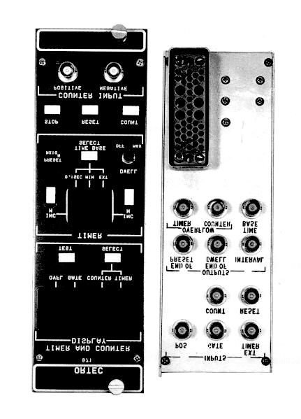
7 1 ORTEC 871 TIMER AND COUNTER 1. DESCRIPTION 1.1. PURPOSE The ORTEC 871 is a modular general purpose instrument that includes an 8-decade counter and an 8-decade presettable counter with a time base. For indentification purposes, the presettable counter portion of the module is called a timer since the combination of a counter with a timer is a common class of instrument. The 871 features great flexibility for system applications. For example, it can be used in the classic arrangement in which the presettable portion counts pulses from an internal time base and controls the total time during which the counter portion counts input pulses from some external source. In this arrangement, the 871 can be preset to count from 0.1 second to 90,000,000 minutes, or the preset feature can be turned off and the timer will count and indicate the time during which the counter is permitted to count input pulses. For a different application, external pulses can be furnished to the presettable portion, as well as to the non-presettable counter, and a ratio of counts from two sources can be obtained by relating the accumulated count totals in the two counters. For this application, if a time measurement were desirable, it could be made with an external timer module that is started, gated, and stopped together with the 871. The two counting portions of the 871 can be cascaded to provide a total capacity of 16 decades. If input counts are furnished into the nonpresettable counter, and its overflow is used as an external input to the presettable counter, it is possible to preset a count level with any of the eight most significant digits of the 16-digit accumulation. For the first time, this instrument offers a new and unique arrangement of the two counting portions. It is possible to use the presettable portion as a counter and, at the same time, furnish 0.1 second pulses from the internal time base into the nonpresettable portion of the instrument. Using this arrangement, it is possible to measure the time required to accumulate a preset number of counts. Both counting portions of the 871 accept NIMstandard slow positive logic signals. The counter section also accepts NIM-standard fast negative input logic pulses. The input count rate is guaranteed to 25 MHz with a 40-nanosecond pulse pair resolution. An overflow output pulse is available from each of the counters to be used when a capacity of more than eight decades is desired. The count, stop, reset, and gating functions are imposed on both counting sections simultaneously GENERAL DESCRIPTION The ORTEC 871 Counter and Timer is built into a double-width NIM module that must be installed in a NIM-standard bin and power supply, such as the ORTEC 401/402 Series, for operation. Positive inputs to the counter can be furnished through either a front or rear panel connector. The negative input to the counter is accommodated on the front panel. The positive input to the timer portion is accepted through a rear panel connector. A Gate LED indicator in the data display area of the front panel lights when both sections of the 871 are in a counting condition. The gate is controlled by Stop and Count pushbuttons on the front panel, by the internal preset condition, and by the rear panel Gate and Count input circuits. Reset is generated automatically when power is applied to the module from the bin and power supply. Reset can also be provided manually by pressing the front panel Reset pushbutton at any time, whether the 871 is counting or not. Reset can also be provided at any time by a signal through the rear panel Reset connector. All eight digits for either the counter portion or the timer portion of the 871 are included in the display area at the top of the front panel. An LED below the eight digits lights to indicate whether the current reading is for the counter portion or for the timer. The Select pushbutton below the display area permits the operator to alternate between the two data sources. Also included in this display area are an LED to show when the instrument is in a
8 2 counting condition (the Gate LED lights to indicate this) and an OVFL LED that lights at the first overflow of the counting portion that is currently being displayed. Prior to the first overflow, the display has leading zero suppression. A test pushbutton can be pressed at any time to light all seven LED segments of all eight digital characters in this display area and also all seven segments of both digital characters in the display area in the Timer portion of the front panel. The Timer portion of the panel includes the preset selectors, a time base selector, and a Dwell control. Preset is effective at a count level in the Timer portion of the instrument, and the count level is selected by the INC M and INC N pushbuttons. The display area includes two digital characters to indicate the current selection of a value for M and a value for N, and the preset level is M 10 N Time Base Selection. Pressing the INC M switch will increment the selection of a digit for M in the formula, which can be any number from 0 through 9. When M = 0, the preset feature is turned off. Pressing the INC N switch will increment the selection of a digit for N in the formula, which can be any number from 0 through 7. Thus preset can be any number that has one significant digit from through When that number of counts has accumulated in the Timer portion of the 871, the instrument is gated off and stops counting in both counting sections. The Dwell control can be rotated to select a delay of less than one second to about 15 seconds following a preset condition, during which the contents of the counters can be read. At the end of the dwell interval, the instrument is reset and starts another counting interval immediately. If the Dwell control is turned fully counterclockwise, the instrument is not reset automatically and the data can be read at the operator s leisure before reset. There are three sources of data from which to select the input for the timer portion of the 871. The Time Base Select pushbutton permits the operator to choose which of the sources is effective at any time, and the selection is monitored by three LEDs at the bottom of the timer display area. When 0.1 SEC is selected, the timer counts pulses that are derived from the internal crystal-controlled precision time base at 0.1 second intervals, and the 0.1 second pulses are also available at the rear panel Time Base output connector; when the 8-digit readout at the top of the front panel displays the Timer data, a decimal point is also illuminated between the first and second decades in the display. When MIN is selected, the timer counts pulses that are derived from the internal crystalcontrolled precision time base at 1 minute intervals, and the one-minute pulses are also available at the rear panel Time Base output connector. When EXT is selected, the timer counts pulses that are furnished through the rear panel Ext Timer connector and the internal precision time base provides 0.1 second output pulses through the rear panel Time Base output connector; note that these output pulses are from a free-running source so they are not synchronized with the Count-Stop operation of the instrument and are not affected by any gating that may be imposed. 2. SPECIFICATIONS 2.1. PERFORMANCE COUNT CAPACITY Eight decades in each of the two sections. COUNTING RATE 25 Mhz guaranteed, both sections. TIME BASE 0.1 second and 1 minute increments derived from a 1 Mhz crystal-controlled oscillator; instability <2 ppm/(c, 0 to 50(C; inaccuracy <5ppm; time base register controlled by counting gate. PULSE PAIR RESOLUTION 40 ns minimum. AUTOMATIC RESET Generated when power is applied INDICATORS COUNTER/TIMER DISPLAY Contains eight characters, 7 LED segments per character, plus decimal point. TIMER PRESET Contains two characters, 7 LED segments per character. GATE An LED illuminates when the unit is in the counting condition.
9 3 OVFL An LED illuminates from the first overflow of the counter or timer that is currently being displayed. COUNTER An LED illuminates when counter data are being displayed. TIMER An LED illuminates when timer data are being displayed. 0.1 SEC An LED illuminates when the time base is 0.1 second. MIN An LED illuminates when the time base is 1 minute. EXT An LED illuminates when the timer section is selected to count pulses that are input through the rear panel Ext Input CONTROLS TEST Pushbutton switch illuminates all seven segments in each of the ten digital characters in the displays; a character reads 8 when all seven segments are lighted. SELECT Pushbutton switch in the Display portion of the front panel permits alternate selection of the register whose counts are displayed, either Counter or Timer. INC M Pushbutton used to select the significant digit of a preset value where preset = M 10 N Time Base. This switch increments the value of M, indicated in the adjacent display, each time it is pressed. M = 0 is preset off; M = 9 is maximum value. INC N Pushbutton used to select the power of 10 for the value of N in the preset formula. This switch increments the value of N, as indicated in the adjacent display, each time it is pressed. N can be any digit, 0 through 7. TIME BASE SELECT Pushbutton switch in the Timer portion of the front panel permits selection of the source of counts for the timer portion of the instrument and determines the source of output through the rear panel Time Base connector; the selection increments through the three possible choices when this switch is pressed. DWELL Single turn control with switch at full counterclockwise setting for Off. Off inhibits recycled operation of a preset counting interval. With the control turned clockwise, recycling is permitted with a dwell time between counting intervals that can be adjusted from about 0.3 second to 15 seconds. STOP Pushbutton switch selects noncounting condition for both portions of the instrument. RESET Pushbutton switch resets the internal registers for both counting portions of the instrument and for the time base register, and turns off the OVFL indicator. COUNT Pushbutton switch enables counting condition for both portions of the instrument, provided the timer is not at its preset level and the Gate input is not held below +1.5 V INPUTS COUNTER POSITIVE Front and rear panel BNC connectors; either accepts positive unipolar or bipolar signals to ±10 V linear, ±25 V max; threshold set at +1.5 V; minimum pulse width above threshold 20 ns. Z in = 1K to ground, DC-coupled. COUNTER NEGATIVE Front panel BNC connector accepts fast negative logic pulses, 16 ma into 50; threshold set at -250 mv; minimum pulse width over threshold 4 ns; input protected to ±25 V at 10% duty cycle. EXT TIMER Rear panel BNC connector; accepts positive unipolar or bipolar signals to ±10 V linear, ±25 V max, and counts these pulses in the timer portion of the instrument if the Time Base Select is set at EXT; threshold set at +1.5 V; minimum pulse width above threshold 20 ns. Z in = 1K to ground, DC-coupled. When using the Ext Timer input and Preset operation, the minimum setting is M = 1 and N = 1 for 25 MHz operation. GATE Rear panel BNC accepts standard slow positive logic or DC level to control the input gate for both counting sections; >+3 V or open circuit allows counting; <+1.5 V inhibits counting; 25 V max; driving source must be capable of sinking 0.5 ma positive current during inhibit.
10 4 COUNT Rear panel BNC accepts standard slow positive logic signal to remotely initiate a counting condition; >+3 V for >100 ns to start the counting condition; 25 V max. Z in = 6K to ground, DCcoupled. RESET Rear panel BNC accepts standard slow positive logic signal to remotely reset both counting sections and the time base register to zero; >+3 V to reset; <+1.5 V or open to not reset; 25 V max; pulse width > 100 ns. Z in = 6K to ground, DCcoupled OUTPUTS NOTE: All outputs are through BNC connectors on the rear panel and are shortcircuit protected. END OF PRESET Provides a standard slow positive logic pulse at the end of each preset interval; nominally +5 V, 5.0 µs wide, through <10, DC-coupled. END OF DWELL Provides a standard slow positive logic pulse at the end of each dwell interval; nominally +5 V, 500 ns wide, through <10, DCcoupled. INTERVAL Provides a positive level signal through the duration of each counting condition interval; nominally +5 V through <30, DC-coupled. TIME BASE Provides standard slow positive logic pulse at intervals that are determined by the Time Base Select function on the front panel. For 0.1 SEC and MIN selections, the signals through the connector are the same as those that are furnished to the Timer section, and these are present only when the Gate input is not held below +1.5 V and the preset condition has not been reached. For the EXT selection, the signals through the rear panel connector are at 0.1 second intervals and are furnished from a free-running oscillator and countdown circuit. Nominally +5 V, 500 ns wide, through <10, DC-coupled. TIMER OVERFLOW Provides a standard slow positive logic pulse at each overflow of the Timer section from 99,999,999 to 0. Nominally +5 V, 500 ns wide, through <10, DC-coupled. COUNTER OVERFLOW Provides a standard slow positive logic pulse at each overflow of the Counter section from 99,999,999 to 0. Nominally +5 V, 500 ns wide, through <10, DC-coupled ELECTRICAL AND MECHANICAL POWER REQUIRED +12 V, 280 ma; -12 V, 117 ma; +24 V, 161 ma; 110 V, 40 ma. DIMENSIONS NIM-standard double-width module, 2.70 by in. front panel, per TID (Rev). 3. INSTALLATION 3.1. GENERAL The 871 Timer and Counter operates on input power that must be furnished from a NIM-standard Bin and Power Supply such as the ORTEC Series. If any vacuum tube equipment is operated in the same rack with the 871, there must be sufficient cooling air circulating to prevent any localized heating of the integrated circuitry used throughout the 871. The temperature of equipment mounted in racks can easily exceed the maximum limits of 120(F (50(C) unless precautions are taken CONNECTION TO POWER Turn off the Bin Power Supply when inserting or removing any modules. The ORTEC modules are designed so that it is not possible to overload the Power Supply with even a full complement of modules in the Bin. Since, however, this may not be true when the Bin contains modules other than those of ORTEC design, the Power Supply voltages should be checked after all modules have been inserted. The 4001/4002 has test points on the Power Supply control panel to permit monitoring the DC voltages easily. When power is turned on for the Bin and Power Supply in which the 871 is installed for operation, the power is automatically turned on for the 871. When power is first applied, an automatic reset function in the 871 resets its counters and time base register to zero, and provides a standard set of startup conditions.
11 5 When using the 871 outside the 4001/4002 Bin and Power Supply, be sure that the power extension cable that is used properly accounts for extension of the AC power and for the power supply grounding circuits that are provided according to the recommended AEC standards outlined in TID (Rev). Both high-quality and power return ground connections are provided to ensure proper reference voltage feedback into the power supply, and these must be preserved in remote cable installations. Be careful also to avoid ground loops when the module is operated outside the bin SIGNAL CONNECTIONS COUNTER INPUTS The 871 accepts and counts either fast negative logic pulses or slow positive logic pulses. Determine the type of input pulses that will be furnished and use the appropriate input connector. Positive logic or analog signals can be connected to either the front or rear panel Positive input connector. These two connectors are not isolated from each other, so signals from two sources should not be connected simultaneously to the two Positive input connectors. The input circuit in the 871 is DC-coupled to eliminate baseline shifts associated with changing counting rates. External capacitance coupling must be provided by the user for signals superimposed on a DC level greater than +1.5 V since the counter is designed to respond to signal transitions through the fixed threshold level of +1.5 V. Negative logic signals for the counter must be furnished to the front panel Negative input connector. The input impedance in this circuit is 50, DC-coupled. This is the standard impedance for which the fast negative logic pulse is defined. There are two important points to remember when supplying signals to either counter input: (1) The signal should cross the threshold level only one time. Signals with overshoot, ringing, etc., will be counted more than once if the discriminator level coincides with a level at which perturbations occur. (2) Signals with slow rise and fall times should be as clean (noise-free) as possible to prevent multiple counting because of the high gain and bandwidth of the 871 discriminator. As a slow signal approaches the threshold, a small spurious noise pulse can traverse the threshold and return, causing an extra count to be added to the contents of the counter. TIMER INPUTS The timer portion of the 871 is a presettable counter. The source of pulses that are counted in this section is a function of operator selection on the front panel, as indicated by LED lights in the display. No connections are required when the selection is either 0.1 SEC or MIN, since the pulses to be counted are furnished from the internal crystal-controlled time base register at either 0.1 second or 1 minute intervals. When the selection is EXT, positive logic or analog signals can be provided through the EXT TIMER connector on the rear panel. The input circuit, using this connector, is the same as was explained for the positive input to the counter section except that there is only one connector that will accommodate the input pulses. GATE INPUT A gate input signal or DC level can be connected to the 871 through the rear panel connector. With no connections made to this BNC, the input voltage level is about +3 V and the counter and timer gate will permit both sections of the unit and the time base register to operate. To cut off the gate, the signal input must be pulled down to below +1.5 V. To do this, the driving circuit must be capable of absorbing 0.5 ma from the gate input circuit. The gate circuit will permit counting when the signal level is +3 V or greater. RESET INPUT A reset input signal can be connected to the 871 through the rear panel BNC Reset connector. To reset the unit to zero, a positive signal of +3 V or greater, with a minimum width of 100 ns, must be used. The input impedance is approximately 6K. Negative signals will not perform any useful function at the Reset input. COUNT INPUT A signal can be furnished through the rear panel Count connector to initiate the counting condition in the 871. To initiate the counting condition, a positive signal of +3 V or greater, with a minimum width of 100 ns, must be used. The input impedance is approximately 6K OUTPUT CONNECTIONS END OF PRESET A standard positive logic pulse through this connector can be used to signal an external instrument that the preset count level in the timer channel has been reached. Its use is optional and depends on the relevance of this information to operation of the external equipment.
12 6 END OF DWELL If preset is being used and automatic recycling is also selected by the front panel controls, an adjusted period of dwell will occur following each preset condition during which the data can be read. At the end of dwell, an internal automatic reset of both counting sections will start a new counting interval. A signal through this connector indicates when the reset occurs and thus when the new counting interval begins. INTERVAL A DC level is available through this connector that monitors the counting condition in the 871. When the unit is able to count, the DC level is at a nominal +5 V; when counting is inhibited (by gating, by having reached preset, or by being manually stopped), the DC level is at nominal ground. The output through this connector can be used to gate a counting condition in another instrument, or for any other similar function. TIME BASE OUTPUT The signals available through this connector are timing units, selected by the front panel Time Base Select operation. When the input to the timer section of the 871 is 0.1 SEC or MIN, as shown by the LED in the display, a pulse is furnished through this connector that is simultaneous with each pulse that is furnished from the time base register to the Timer section. When the input to the timer section of the 871 is EXT, pulses are furnished through this connector at 0.1 second intervals from a free-running oscillator circuit; internal gating does not affect the accumulation of time base counts to generate the 0.1 second intervals and to generate the output pulses. TIMER OVERFLOW The Timer Overflow output signal is available through its BNC on the rear panel. A slow positive logic signal appears at this connector each time the contents of the timer section of the 871 change from to 0. The output signal is 500 ns wide, and can be used as the input signal to another counter to increase the total counting capacity beyond the eight decades that are included in the 871 Timer section. Note that an overflow in this presettable section can occur only if the preset function is turned off. COUNTER OVERFLOW The Counter Overflow output signal is available through its BNC on the rear panel. A slow positive logic signal appears at this connector each time the contents of the counter section of the 871 change from to 0. The output signal is 500 ns wide and can be used as the input signal to another counter to increase the total counting capacity beyond the eight decades that are included in the 871 Counter section. 4. OPERATIONS 4.1. STANDARD OPERATION The ORTEC 871 Timer and Counter is an instrument that is designed for standard use as a counter that operates during a preset amount of time and then stops at the operator-selected preset time. It can stop and hold the data until it is reset manually or by a remote signal, or it can dwell at the preset stop for an adjusted short time interval while the data are copied and then reset and start a new counting interval automatically. For this type of operation, connect the source of pulses to be counted to a Counter Input - either positive or negative as appropriate. The use of a Gate input is optional, depending on the experimental requirements. Determine the time during which pulses will be counted. If this is not known, the preset can be set at off and a counting interval can be controlled manually, using the Stop and Count switches on the front panel. To set the preset function at off, press INC M repeatedly until the adjacent digital character in the display reads 0. To preset the timer at any other count level, press INC M to select the significant digit and then press INC N to select the power of ten for a multiplier. For example, to preset 600, set M=6 and N=2 (600 = ). Use the Time Base Select switch to select either 0.1 SEC or MIN for the unit of time. When the selection is 0.1 SEC, a decimal point will appear in the display to aid in interpretation. In the above example, the preset 600 time base units could be either 60.0 seconds or 600 minutes, depending on this selection.
13 7 Set the Dwell control as desired. To turn it off, rotate the control fully counterclockwise to actuate the switch. After an operating routine has been established, turn this control to adjust the dwell interval that follows each preset counting interval so that the data can be copied before the 871 is reset. To monitor the Counter data accumulation, press Select in the Display portion of the front panel until the COUNTER LED lights. Each time this switch is pressed, the number displayed by the eight digital characters in this display will alternate between the counter and the timer. To start a counting interval, press Stop; then press Reset; and then press Count. To stop the counting interval manually, press Stop. If desired, the counting interval can then be resumed from the point of interruption by pressing Count without using Reset. Note that the Reset and Count commands can be duplicated remotely by signals through rear panel connectors PRESET COUNT OPERATION When the EXT TIMER connector on the rear panel is used as the input circuit for pulses to be counted and the Time Base Select switch is used to select the EXT mode for timer operation, the timer section of the 871 operates as a counter that can be preset as desired. For this type of operation, furnish positive logic pulses through the EXT TIMER BNC and preset the unit as described above for standard operation. When this type of operation is to be used, the time base operates to generate 0.1 second pulses and provides them through the rear panel Time Base Output connector. If desired, these pulses can be furnished to the Pos Input connector of the Counter section of the unit, and time units can be counted in the nonpresettable section of the instrument. The operator must be aware that the units are 0.1 second increments because the decimal point will not appear in the display to indicate this fact. Also, the accumulated count will be displayed when the Timer LED is lighted, and the time will be displayed when the Counter LED is lighted HIGH CAPACITY PRESET COUNT OPERATION By furnishing the Counter Overflow signal into the EXT Timer input and setting the Time Base Select for EXT operation, a counter can be created that includes 16 decades of data and it can be preset at any level in decades 9 through 16. Either positive or negative input pulses can be accommodated since they are furnished into the Counter section of the instrument; the overflow output pulses are compatible with the external timer input requirements. The Time Base output is a series of pulses at 0.1 second increments, and these can be counted in an accessory counter if desired. 5. MAINTENANCE 5.1. GENERAL The ORTEC 871 Timer and Counter should require very little maintenance other than the replacement of some parts that may deteriorate with age. The circuit description in Section 5 can aid in troubleshooting if this is required FACTORY REPAIR This instrument can be returned to the ORTEC factory for service and repair at a nominal cost. Our standard procedure for repair ensures the same quality control and checkout that are used for a new instrument. Always contact the Customer Service Department at ORTEC, (865) , before sending in an instrument for repair to obtain shipping instructions and so that the required Return Authorization Number can be assigned to the unit. Write this number on the address label and on the package to ensure prompt attention when it reaches the ORTEC factory.
14 8 Bin/Module Connector Pin Assignments For Standard Nuclear Instrument Modules per DOE/ER-0457T. Pin Function Pin Function 1 +3 V 23 Reserved 2 3 V 24 Reserved 3 Spare bus 25 Reserved 4 Reserved bus 26 Spare 5 Coaxial 27 Spare 6 Coaxial * V 7 Coaxial *29 24 V V DC 30 Spare bus 9 Spare 31 Spare *10 +6 V 32 Spare *11 6 V * V AC (hot) 12 Reserved bus *34 Power return ground 13 Spare 35 Reset (Scaler) 14 Spare 36 Gate 15 Reserved 37 Reset (Auxiliary) * V 38 Coaxial *17 12 V 39 Coaxial 18 Spare bus 40 Coaxial 19 Reserved bus * V AC (neutral) 20 Spare *42 High-quality ground 21 Spare G Ground guide pin 22 Reserved Pins marked (*) are installed and wired in ORTEC s 4001A and 4001C Modular System Bins.
Model CO4020 Quad 4-Input Logic Unit Operating and Service Manual
 Model CO4020 Quad 4Input Logic Unit Operating and Service Manual Printed in U.S.A. ORTEC Part No. 762000 1202 Manual Revision C Advanced Measurement Technology, Inc. a/k/a/ ORTEC, a subsidiary of AMETEK,
Model 579 Fast-Filter Amplifier Operating and Service Manual
 Model 579 Fast-Filter Amplifier Operating and Service Manual Printed in U.S.A. ORTEC Part No. 733530 1202 Manual Revision C Advanced Measurement Technology, Inc. a/k/a/ ORTEC, a subsidiary of AMETEK, Inc.
Model 974A Quad Counter/Timer Operating Manual
 ORTEC Model 974A Quad Counter/Timer Operating Manual Printed in U.S.A. ORTEC Part No. 932501 0210 Manual Revision A Advanced Measurement Technology, Inc. a/k/a/ ORTEC, a subsidiary of AMETEK, Inc. WARRANTY
VK-P10SE WARRANTY REGISTRATION FORM
 VK-P10SE WARRANTY REGISTRATION FORM Unit Serial Number: Customer Name: Address: Date of Purchase: Purchased From: Dealer Name: Address: IMPORTANT NOTE: In order to receive the full five-year product warranty,
Electronic M.O.P Card. Instruction Manual Model D
 Electronic M.O.P Card Instruction Manual Model D10341-000 Table of Contents 1. General Description................................................................ 1 2. Specifications.....................................................................
LEVEL ADJUST POWER Shiloh Road Alpharetta, Georgia (770) FAX (770) Toll Free
 FAX (770) Toll Free") Instruction Manual Model 1200-07 Amplifier September 2010 Rev A MONITOR J1 LEVEL ADJUST POWER MODEL 1200 AMPLIER CROSS TECHNOLOGIES, INC. Data, drawings, and other material contained herein are proprietary
Instruction Manual Model 1200-07 Amplifier September 2010 Rev A MONITOR J1 LEVEL ADJUST POWER MODEL 1200 AMPLIER CROSS TECHNOLOGIES, INC. Data, drawings, and other material contained herein are proprietary
USER INSTRUCTIONS MODEL CSI-200 COAXIAL SYSTEM INTERFACE
 USER INSTRUCTIONS MODEL CSI-200 COAXIAL SYSTEM INTERFACE 9350-7676-000 Rev B, 5/2001 PROPRIETARY NOTICE The RTS product information and design disclosed herein were originated by and are the property of
Kramer Electronics, Ltd. USER MANUAL. Model: PT-102VN. 1:2 Video DA
 Kramer Electronics, Ltd. USER MANUAL Model: PT-102VN 1:2 Video DA Contents Contents 1 Introduction 1 2 Getting Started 1 2.1 Quick Start 2 3 Overview 3 4 Your PT-102VN 1:2 Video DA 4 5 Using the PT-102VN
Kramer Electronics, Ltd. USER MANUAL. Models: OC-1N, Video Isolator OC-2, Dual Channel Video Isolator OC-4, Quad Channel Video Isolator
 Kramer Electronics, Ltd. USER MANUAL Models: OC-1N, Video Isolator OC-2, Dual Channel Video Isolator OC-4, Quad Channel Video Isolator Contents Contents 1 Introduction 1 2 Getting Started 1 2.1 Quick Start
Model /29S RF Splitter
 Instruction Manual Model 1584-29/29S RF Splitter March 2013, Rev. 0 LNB VOLTAGE A B MODEL 1584 COMBINER CROSS TECHNOLOGIES INC. GND+DC ON Data, drawings, and other material contained herein are proprietary
Instruction Manual Model # Block Upconverter
 Instruction Manual Model 2115-278# Block Upconverter August 2018, Rev. A MODEL 2115 UPCONVERTER CROSS TECHNOLOGIES INC. EXT 10MHZ ALARM POWER Data, drawings, and other material contained herein are proprietary
SK2002DA SIDEKICKER 1-IN, 2-OUT VGA-UXGA DISTRIBUTION AMPLIFIER CABLE USER S GUIDE DISTRIBUTION AMPLIFIERS
 MANUAL PART NUMBER: 400-0152-001 PRODUCT REVISION: 0 SK2002DA SIDEKICKER 1-IN, 2-OUT VGA-UXGA DISTRIBUTION AMPLIFIER CABLE USER S GUIDE TABLE OF CONTENTS Page PRECAUTIONS / SAFETY WARNINGS...2 GENERAL...2
Kramer Electronics, Ltd. USER MANUAL. Model: 810B. Black Burst / Audio Generator
 Kramer Electronics, Ltd. USER MANUAL Model: 810B Black Burst / Audio Generator Contents Contents 1 Introduction 1 2 Getting Started 1 3 Your 810B Black Burst / Audio Generator 1 4 Connecting the 810B Black
KHT 1000C HV-Probe Calibrator. Instruction Manual
 KHT 1000C HV-Probe Calibrator Instruction Manual Copyright 2015 PMK GmbH All rights reserved. Information in this publication supersedes that in all previously published material. Specifications are subject
DA1909 COMPUTER VIDEO LINE DRIVER WITH EQUALIZATION USER S GUIDE
 MANUAL PART NUMBER: 400-0108-002 PRODUCT REVISION: 1 COMPUTER VIDEO LINE DRIVER WITH EQUALIZATION USER S GUIDE INTRODUCTION Altinex appreciates your purchase of the Line Driver. We are sure you will find
Kramer Electronics, Ltd. USER MANUAL. Model: VM Video Component Distributor
 Kramer Electronics, Ltd. USER MANUAL Model: VM-1045 Video Component Distributor Contents Contents 1 Introduction 1 2 Getting Started 1 2.1 Quick Start 1 3 Overview 3 4 Your VM-1045 Video Component Distributor
Instructions. P MHz 1X/10X Passive Probe
 Instructions P2100 100 MHz 1X/10X Passive Probe 071-0774-01 071077401 Copyright Tektronix, Inc. All rights reserved. Tektronix products are covered by U.S. and foreign patents, issued and pending. Information
DISTRIBUTION AMPLIFIER
 MANUAL PART NUMBER: 400-0045-005 DA1907SX 1-IN, 2-OUT VGA/SVGA/XGA/UXGA DISTRIBUTION AMPLIFIER USER S GUIDE TABLE OF CONTENTS Page PRECAUTIONS / SAFETY WARNINGS... 2 GENERAL...2 GUIDELINES FOR RACK-MOUNTING...2
Digital Delay / Pulse Generator DG535 Digital delay and pulse generator (4-channel)
") Digital Delay / Pulse Generator Digital delay and pulse generator (4-channel) Digital Delay/Pulse Generator Four independent delay channels Two fully defined pulse channels 5 ps delay resolution 50 ps
Digital Delay / Pulse Generator Digital delay and pulse generator (4-channel) Digital Delay/Pulse Generator Four independent delay channels Two fully defined pulse channels 5 ps delay resolution 50 ps
Kramer Electronics, Ltd. USER MANUAL. Model: VA-14. 4x1 Balanced Audio Mixer
 Kramer Electronics, Ltd. USER MANUAL Model: VA-14 4x1 Balanced Audio Mixer Contents Contents 1 Introduction 1 2 Getting Started 2.1 Quick Start 1 1 3 Overview 3 4 Your VA-14 4x1 Balanced Audio Mixer 4
Instruction Manual Model BlockUpconverter
 Instruction Manual Model 2115-55 BlockUpconverter June 2009 - Rev. 0 MODEL 2115 UPCONVERTER CROSS TECHNOLOGIES INC. EXT 10MHZ ALARM POWER Data, drawings, and other material contained herein are proprietary
LEVEL ADJUST POWER Shiloh Road Alpharetta, Georgia (770) FAX (770) Toll Free
 FAX (770) Toll Free") Instruction Manual Model 1200-75 Amplifier August 2012, Rev. A LEVEL ADJUST POWER MODEL 1200 AMPLIFIER CROSS TECHNOLOGIES, INC. Data, drawings, and other material contained herein are proprietary to Cross
Instruction Manual Model 1200-75 Amplifier August 2012, Rev. A LEVEL ADJUST POWER MODEL 1200 AMPLIFIER CROSS TECHNOLOGIES, INC. Data, drawings, and other material contained herein are proprietary to Cross
Kramer Electronics, Ltd. USER MANUAL. Model: VS-33Vxl. 3x1 Video Switcher
 Kramer Electronics, Ltd. USER MANUAL Model: VS-33Vxl 3x1 Video Switcher Contents Contents 1 Introduction 1 2 Getting Started 1 2.1 Quick Start 1 3 Overview 3 3.1 Recommendations for Achieving the Best
Kramer Electronics, Ltd. USER MANUAL. Models: TR-1YC, s-video Isolation Transformer TR-2YC, s-video Dual Isolation Transformers
 Kramer Electronics, Ltd. USER MANUAL Models: TR-1YC, s-video Isolation Transformer TR-2YC, s-video Dual Isolation Transformers Contents Contents 1 Introduction 1 2 Getting Started 1 2.1 Quick Start 1 3
Kramer Electronics, Ltd.
 Kramer Electronics, Ltd. Preliminary USER MANUAL Model: 6241HDxl 4x1 3G HD-SDI Switcher Contents Contents 1 Introduction 1 2 Getting Started 1 2.1 Quick Start 2 3 Overview 3 4 Defining the 6241HDxl 4x1
AES-402 Automatic Digital Audio Switcher/DA/Digital to Analog Converter
 Broadcast Devices, Inc. AES-402 Automatic Digital Audio Switcher/DA/Digital to Analog Converter Technical Reference Manual Broadcast Devices, Inc. Tel. (914) 737-5032 Fax. (914) 736-6916 World Wide Web:
NS-3 RF Noise Source Operation Manual
 RF Noise Source Operation Manual Version 2.04 June 3, 2016 SPECIFICATIONS Frequency... Maximum output level... Output flatness... (at max output level) Impedance... Displayed level... Repeatability...
Kramer Electronics, Ltd. USER MANUAL. Model: VP-100. VGA/XGA to RGBHV Converter
 Kramer Electronics, Ltd. USER MANUAL Model: VP-100 VGA/XGA to RGBHV Converter Contents Contents 1 Introduction 1 2 Getting Started 1 2.1 Quick Start 1 3 Overview 3 4 Your VP-100 VGA/XGA to RGBHV Converter
45LM Series Modules. Features. Specifications. Plug-in Logic and Display Modules for Q45 Series Photoelectric Sensors
 Plug-in Logic and Display Modules for Q45 Series Photoelectric Sensors Three plug-in modules are available: Features Model 45LM58 45LM58D 45LMD Functions Selectable output timing Selectable output timing,
SAWM60 AUDIO/VIDEO MODULATOR
 SAWM60 LIMITED WARRANTY Holland Electronics LLC, warrants that the product enclosed with this Limited Warranty statement will conform to the manufacturer s specifications and be free of defects in the
THE ASTRO LINE SERIES GEMINI 5200 INSTRUCTION MANUAL
 THE ASTRO LINE SERIES GEMINI 5200 INSTRUCTION MANUAL INTRODUCTION The Gemini 5200 is another unit in a multi-purpose series of industrial control products that are field-programmable to solve multiple
Kramer Electronics, Ltd. USER MANUAL. Model: Power Amplifier
 Kramer Electronics, Ltd. USER MANUAL Model: 900 Power Amplifier Contents Contents 1 Introduction 1 2 Getting Started 1 3 Overview 1 4 Your 900 Power Amplifier 2 5 Connecting your 900 Power Amplifier 4
Model P/03P Upconverters
 Instruction Manual Model 2005-02P/03P Upconverters October 2013, Rev H 2005 TEST UPCONVERTER GHz 100MHz10MHz 1MHz C KU 70 140 IF IN GAIN DC POWER +DC IN +15V, 200 ma RF OUT DC ALARM LO IF FREQUENCY J1
Kramer Electronics, Ltd. USER MANUAL. Model: VS-211HDxl. 3G HD-SDI Automatic Standby Switcher
 Kramer Electronics, Ltd. USER MANUAL Model: VS-211HDxl 3G HD-SDI Automatic Standby Switcher Contents Contents 1 Introduction 1 2 Getting Started 1 2.1 Quick Start 2 3 Overview 3 4 Your VS-211HDxl 3G HD-SDI
Kramer Electronics, Ltd. USER MANUAL. Model: VM-3A. Audio Distributor
 Kramer Electronics, Ltd. USER MANUAL Model: VM-3A Audio Distributor Contents Contents 1 Introduction 1 2 Getting Started 1 2.1 Quick Start 2 3 Overview 3 4 Your Audio Distributor 4 5 Connecting Your Audio
USERS GUIDE MCX-HTS. HDMI to 3G SDI Converter. Manual Number:
 USERS GUIDE MCX-HTS HDMI to 3G SDI Converter i Manual Number: 151226 SAFETY INSTRUCTIONS Please review the following safety precautions. If this is the first time using this model, then read this manual
OPERATOR MANUAL OSD8865 DIGITAL TRIPLE VIDEO FIBER OPTIC RECEIVER
 OPERATOR MANUAL OSD8865 DIGITAL TRIPLE VIDEO FIBER OPTIC RECEIVER INDEX 1 1 TECHNICAL SUMMARY... 4 1.1 BRIEF DESCRIPTION... 4 1.1.1 OVERVIEW... 4 1.1.2 APPLICATIONS... 4 1.1.3 FEATURES AND BENEFITS...
OPERATOR MANUAL OSD351 FIBRE OPTIC CCTV TRANSMITTER CARD
 OPERATOR MANUAL OSD351 FIBRE OPTIC CCTV TRANSMITTER CARD OSD351 FIBRE OPTIC CCTV TRANSMITTER CARD Document No:10103701 PAGE 2 C O N T E N T S 1. TECHNICAL SUMMARY...4 1.1 BRIEF DESCRIPTION...4 1.2 TECHNICAL
SyncGen. User s Manual
 SyncGen User s Manual 1 IMPORTANT SAFETY INSTRUCTION READ FIRST This symbol, whenever it appears, alerts you to the presence of uninsulated dangerous voltage inside the enclosure-voltage that may be sufficient
LIGHT COPILOT II. elationlighting.com Internet:
 LIGHT COPILOT II E-mail: info@ elationlighting.com Internet: http://www.elationlighting.com 1 Introduction Thank you for your purchase of the LIGHT COPILOT II. The LIGHT COPILOT II is an intelligent lighting
USER MANUAL. Kramer Electronics, Ltd. Models:
 Kramer Electronics, Ltd. USER MANUAL Models: 103AV, 1:3 Audio-Stereo / Video DA 104M, 1:4 Microphone Amplifier 105A, 1:5 Stereo Audio DA 105S, 1:5 High Resolution s-video DA 105V, 1:5 High Resolution Video
Kramer Electronics, Ltd. USER MANUAL. Models: PT-102AN, 1:2 Audio DA PT-102SN, 1:2 s-video DA
 Kramer Electronics, Ltd. USER MANUAL Models: PT-102AN, 1:2 Audio DA PT-102SN, 1:2 s-video DA Contents Contents 1 Introduction 1 2 Getting Started 1 2.1 Quick Start 1 3 Overview 3 3.1 About the PT102AN
TL MEMORY CONTROL CONSOLE OWNERS MANUAL 02/17/2005. Version 0.6
 TL - 3012 MEMORY CONTROL CONSOLE OWNERS MANUAL Version 0.6 02/17/2005 Page 2 of 6 SPECIFICATIONS Channels: 12 Operating modes: Two Scene Manual Mode Preset Scene Playback Mode Chase Mode Output connector:
INSTRUCTION BOOK FOR. Lectern
 INSTRUCTION BOOK FOR Lectern Disclaimer Milestone and its affiliated corporations and subsidiaries (collectively "Milestone"), intend to make this manual accurate and complete. However, Milestone makes
Metal Electrode Meter
 Metal Electrode Meter INSTRUCTION MANUAL FOR Metal Electrode Meter MODEL 2900 Serial # Date PO Box 850 Carlsborg, WA 98324 U.S.A. 360-683-8300 800-426-1306 FAX: 360-683-3525 http://www.a-msystems.com Version
HMA-860H AGILE MODULATOR
 HMA-860H AGILE MODULATOR LIMITED WARRANTY Holland Electronics LLC, warrants that the product enclosed with this Limited Warranty statement will conform to the manufacturer s specifications and be free
Kramer Electronics, Ltd.
 Kramer Electronics, Ltd. Preliminary USER MANUAL Model: FC-332 SD/HD-SDI to HDMI Converter/DA Contents Contents 1 Introduction 1 2 Getting Started 1 2.1 Quick Start 1 3 Overview 2 3.1 About HDMI 3 3.2
CHECK LINE. Model LS-36-LED. Stationary Stroboscope. Operating Manual BY ELECTROMATIC
 CHECK LINE BY ELECTROMATIC Stationary Stroboscope Model LS-36-LED Operating Manual Table of Contents 1.0 Introduction... 02 1.1 Unpacking 1.2 Optional Accessories 2.0 Safety Information... 3 3.0 Controls...
Kramer Electronics, Ltd. USER MANUAL. Models: 6808, SDI-AES De-Embedder 6809, SDI-AES Embedder
 Kramer Electronics, Ltd. USER MANUAL Models: 6808, SDI-AES De-Embedder 6809, SDI-AES Embedder Contents Contents 1 Introduction 1 2 Getting Started 1 3 Overview 1 3.1 About the 6808 SDI-AES De-Embedder
User Guide. Single-Link DVI Active Cable Extender. DVI-7171c
 User Guide Single-Link DVI Active Cable Extender DVI-7171c TABLE OF CONTENTS SECTION PAGE PRODUCT SAFETY...1 PRODUCT LIABILITY...1 1.0 INTRODUCTION...2 2.0 SPECIFICATIONS...3 3.0 PACKAGE CONTENTS...4 4.0
User Manual. 4x2 Composite Video/S-Video/Analog Audio Matrix Switcher AT-SAV-42M
 User Manual 4x2 Composite Video/S-Video/Analog Audio Matrix Switcher AT-SAV-42M www.atlona.com TABLE OF CONTENTS 1. Introduction... 2 2. Features... 2 3. Package Contents... 2 4. Specification... 3 5.
Kramer Electronics, Ltd.
 Kramer Electronics, Ltd. Preliminary USER MANUAL Model: FC-322 SD/HD-SDI to HDMI Converter/Switcher/DA Contents Contents 1 Introduction 1 2 Getting Started 1 2.1 Quick Start 2 3 Overview 2 3.1 About HDMI
User Manual. 1x8 S-Video Distribution Amplifier With Stereo Audio AT-SAV18
 User Manual 1x8 S-Video Distribution Amplifier With Stereo Audio AT-SAV18 www.atlona.com TABLE OF CONTENTS 1. Introduction... 2 2. Features... 2 3. Package Contents... 2 4. Specification... 2 5. Panel
Operation Manual VMS 3.0 Video System
 Operation Manual VMS 3.0 Video System for the AlterG Anti-Gravity Treadmill 1 This manual covers operation procedures for the following AlterG products: AlterG Video System model VMS 3.0 NOTE: The following
Kramer Electronics, Ltd. USER MANUAL. Model: VS x1 Video Audio Switcher
 Kramer Electronics, Ltd. USER MANUAL Model: VS-421 4x1 Video Audio Switcher Contents Contents 1 Introduction 1 2 Getting Started 1 3 Overview 1 4 Your Video Audio Matrix Switcher 2 5 Connecting the Video
HDMI Extender over UTP Cable
 User Manual HDMI Extender over UTP Cable VHDE-300 Tx Rx Features.. Extends HDMI 1080p AV and IR Signals Transmission distance up to 60m/200ft via CAT6 cable or higher grade cable 5V DC, 1A Important Safety
Kramer Electronics, Ltd. USER MANUAL. Model: VP-200N5. 1:2 High Resolution UXGA DA
 Kramer Electronics, Ltd. USER MANUAL Model: VP-200N5 1:2 High Resolution UXGA DA Contents Contents 1 Introduction 1 2 Getting Started 1 2.1 Quick Start 2 3 Overview 2 4 Your VP-200N5 1:2 High Resolution
PRO-HDMI2HD. HDMI to SDI/3G-HD-SD Converter. User Manual. Made in Taiwan
 PRO-HDMI2HD HDMI to SDI/3G-HD-SD Converter User Manual Made in Taiwan rev.1008 103 Quality Circle, Suite 210 Huntsville, Alabama 35806 Tel: (256) 726-9222 Fax: (256) 726-9268 Email: service@pesa.com Safety
Kramer Electronics, Ltd. USER MANUAL. Model: VP-41. 4x1 VGA / XGA Switcher
 Kramer Electronics, Ltd. USER MANUAL Model: VP-41 4x1 VGA / XGA Switcher Contents Contents 1 Introduction 1 2 Getting Started 1 3 Overview 1 4 Your VP-41 4x1 VGA / XGA Switcher 2 5 Connecting the VP-41
Owner s Manual. Backup Monitor System. LCD Monitor & CCD Color Camera
 Backup Monitor System LCD Monitor & CCD Color Camera Backup Monitor System Copyright 2003 TMI Products, Inc. All Rights Reserved Corona, CA U.S.A. 060300 Owner s Manual 1493 Bentley Drive Corona, CA 92879
PAD-2 2 Channel A-D Converter Mk2 Rev. 3 Sept. 24, 2017
 PAD-2 2 Channel A-D Converter Mk2 Rev. 3 Sept. 24, 2017 USER MANUAL 1 Thank you for purchasing our product. We strive to provide you with a professional product, a toolbox you will use for several years
High Performance, Multi-Function Nuclear Multichannel Buffer/Counter/Timer/Rate Meter Hardware Manual
 ORTEC EASY-NIM 928 Suite High Performance, Multi-Function Nuclear Multichannel Buffer/Counter/Timer/Rate Meter Hardware Manual Printed in U.S.A. ORTEC Part No. 93252 4 Manual Revision A Advanced Measurement
6170 Shiloh Road Alpharetta, Georgia (770) FAX (770) Toll Free
 FAX (770) Toll Free") Instruction Manual Model 2115-202 Upconverter November 2011, Rev. C MODEL 2115 UPCONVERTER CROSS TECHNOLOGIES INC. EXT 10MHZ ALARM POWER Data, drawings, and other material contained herein are proprietary
Instruction Manual Model 2115-202 Upconverter November 2011, Rev. C MODEL 2115 UPCONVERTER CROSS TECHNOLOGIES INC. EXT 10MHZ ALARM POWER Data, drawings, and other material contained herein are proprietary
COMPOSITE VIDEO (BNC) TO VGA VIDEO FORMAT CONVERTER AND SCALER AT-RGB110
 TO VGA VIDEO FORMAT CONVERTER AND SCALER AT-RGB110") User Manual COMPOSITE VIDEO (BNC) TO VGA VIDEO FORMAT CONVERTER AND SCALER AT-RGB110 TABLE OF CONTENTS 1. Introduction... 2 2. Package Contents... 2 3. Features... 2 4. Specification... 2 5. Panel Description...
User Manual COMPOSITE VIDEO (BNC) TO VGA VIDEO FORMAT CONVERTER AND SCALER AT-RGB110 TABLE OF CONTENTS 1. Introduction... 2 2. Package Contents... 2 3. Features... 2 4. Specification... 2 5. Panel Description...
1 x 10 Component Video with Stereo and Digital Audio Distribution Amplifier over CAT5/6 compatible with AT-COMP300RL AT-COMP10SS
 1 x 10 Component Video with Stereo and Digital Audio Distribution Amplifier over CAT5/6 compatible with AT-COMP300RL AT-COMP10SS User Manual www.atlona.com TABLE OF CONTENTS 1. Introduction 2 2. Features
Colour Explosion Proof Video Camera USER MANUAL VID-C
 Colour Explosion Proof Video Camera USER MANUAL VID-C Part Number: MAN-0036-00 Rev 4 Copyright 2002 Net Safety Monitoring Inc. Printed in Canada This manual is provided for informational purposes only.
Kramer Electronics, Ltd.
 Kramer Electronics, Ltd. Preliminary USER MANUAL Model: VP-2K 1:2 UXGA / Audio Distributor Contents Contents 1 Introduction 1 2 Getting Started 1 2.1 Quick Start 2 3 Overview 3 4 Your VP-2K 1:2 UXGA /
8024-DSS-02 Issue 2. DSS-8024 Dual Serial Switch USER MANUAL
 8024-DSS-02 Issue 2 DSS-8024 Dual Serial Switch USER MANUAL DSS-8024 Dual Serial Switch User Manual Ross Part Number: 8024-DSS-02 Document Issue: 2 Printing Date: March 15, 2000. Printed in Canada. The
Kramer Electronics, Ltd. USER MANUAL. Model: VP-200Dxl. XGA Differential Amplifier / DA
 Kramer Electronics, Ltd. USER MANUAL Model: VP-200Dxl XGA Differential Amplifier / DA Contents Contents 1 Introduction 1 2 Getting Started 1 3 Overview 1 4 Your XGA Differential Amplifier / DA 2 4.1 Connecting
VGAD-12 ORDERCODE
 VGAD-12 ORDERCODE 101220 Congratulations! You have bought a great, innovative product from DMT. The DMT Media Spinner brings excitement to any venue. Whether you want simple plug-&-play action or a sophisticated
Kramer Electronics, Ltd.
 Kramer Electronics, Ltd. Preliminary USER MANUAL Models: VS-44AV, 4x4 Video Audio Matrix Switcher VS-81AV, 8x1 Video/Audio-Stereo Switcher VS-81AYC, 8x1 s-video/audio-stereo Switcher VS-81V, 8x1 Video
OPERATOR MANUAL OSD390 SERIES 4 CHANNEL VIDEO/AUDIO/DATA FIBER OPTIC TRANSMISSION SYSTEM
 PTY. LTD A.B.N. 83 003 020 504 OPERATOR MANUAL OSD390 SERIES 4 CHANNEL VIDEO/AUDIO/DATA FIBER OPTIC TRANSMISSION SYSTEM OSD390 SERIES 4 CHANNEL VIDEO/AUDIO/DATA FIBER OPTIC TRANSMISSION SYSTEM Document
Installation and Operation Manual. for the. SM-6 Programmable Stereo Mixer
 for the Copyright 1996 2001 by Broadcast Tools, Inc. All rights reserved. Except as permitted under the United States Copyright Act of 1976, no part of this document may be reproduced or distributed without
Kramer Electronics, Ltd. USER MANUAL. Model: PT-101HDCP. DVI Repeater
 Kramer Electronics, Ltd. USER MANUAL Model: PT-101HDCP DVI Repeater Contents Contents 1 Introduction 1 2 Getting Started 1 2.1 Quick Start 1 3 Overview 3 3.1 About HDCP 3 3.2 Recommendations for Best Performance
AES-404 Digital Audio Switcher/DA/Digital to Analog Converter
 Broadcast Devices, Inc. AES-404 Digital Audio Switcher/DA/Digital to Analog Converter Technical Reference Manual Broadcast Devices, Inc. Tel. (914) 737-5032 Fax. (914) 736-6916 World Wide Web: www.broadcast-devices.com
1 x 3 Component Video W/Audio Distribution Amplifier AT-COMP-13AD
 1 x 3 Component Video W/Audio Distribution Amplifier AT-COMP-13AD User Manual www.atlona.com TABLE OF CONTENTS 1. Introduction 2 2. Features 2 3. Package Contents 2 4. Specifications 2 5. Panel View 3
Kramer Electronics, Ltd. USER MANUAL. Model: VM-2DVI. High Resolution / Dual Link 1:2 DVI Distributor
 Kramer Electronics, Ltd. USER MANUAL Model: VM-2DVI High Resolution / Dual Link 1:2 DVI Distributor Contents Contents 1 Introduction 1 2 Getting Started 1 2.1 Quick Start 1 3 Overview 3 4 Your VM-2DVI
Noise Detector ND-1 Operating Manual
 Noise Detector ND-1 Operating Manual SPECTRADYNAMICS, INC 1849 Cherry St. Unit 2 Louisville, CO 80027 Phone: (303) 665-1852 Fax: (303) 604-6088 Table of Contents ND-1 Description...... 3 Safety and Preparation
1X4 HDMI Splitter with 3D Support
 AV Connectivity, Distribution And Beyond... VIDEO WALLS VIDEO PROCESSORS VIDEO MATRIX SWITCHES EXTENDERS SPLITTERS WIRELESS CABLES & ACCESSORIES 1X4 HDMI Splitter with 3D Support Model #: SPLIT-HDM3D-4
APSPB PUSH BUTTON ZERO Installation Manual
 APSPB PUSH BUTTON ZERO Installation Manual CARDINAL SCALE MFG. CO. 8527-0579-0M Rev A 203 E. Daugherty, Webb City, MO 64870 USA Printed in USA 12/14 Ph: 417-673-4631 Fax: 417-673-2153 www.detectoscale.com
User Manual PS-684. HDBaseT Extender Kit 70m. All Rights Reserved. Version: UHBT70P_2016V1.2
 User Manual PS-684 All Rights Reserved Version: UHBT70P_2016V1.2 Preface Read this user manual carefully before using this product. Pictures shown in this manual is for reference only, different model
CS x1 RS-232 Computer Controlled Video Switcher. Instruction Manual
 CS-1600 16x1 RS-232 Computer Controlled Video Switcher Instruction Manual Thank you for purchasing one of our products. Please read this manual before using this product. When using this product, always
User Manual. AtlonA COMPOSITE VIDEO (BNC) + STEREO AUDIO TO HDMI VIDEO FORMAT CONVERTER AND SCALER AT-HD120
 + STEREO AUDIO TO HDMI VIDEO FORMAT CONVERTER AND SCALER AT-HD120") User Manual AtlonA COMPOSITE VIDEO (BNC) + STEREO AUDIO TO HDMI VIDEO FORMAT CONVERTER AND SCALER AT-HD120 TABLE OF CONTENTS 1. Introduction... 3 2. Package Contents... 3 3. Features... 3 4. Specification...
User Manual AtlonA COMPOSITE VIDEO (BNC) + STEREO AUDIO TO HDMI VIDEO FORMAT CONVERTER AND SCALER AT-HD120 TABLE OF CONTENTS 1. Introduction... 3 2. Package Contents... 3 3. Features... 3 4. Specification...
KRAMER ELECTRONICS LTD. USER MANUAL MODEL: VP-2L UXGA Line Amplifier. P/N: Rev 3
 KRAMER ELECTRONICS LTD. USER MANUAL MODEL: VP-2L UXGA Line Amplifier P/N: 2900-000239 Rev 3 Contents 1 Introduction 1 2 Getting Started 2 2.1 Achieving the Best Performance 2 3 Overview 3 3.1 Defining
EXT-3GSDI-FOSM User Manual
 EXT-3GSDI-FOSM User Manual www.gefen.com ASKING FOR ASSISTANCE Technical Support: Telephone (818) 772-9100 (800) 545-6900 Fax (818) 772-9120 Technical Support Hours: 8:00 AM to 5:00 PM PST Monday through
MASTR II BASE STATION 12/24V POWER SUPPLY 19A149979P1-120 VOLT/60 Hz 19A149979P2-230 VOLT/50 Hz
 Mobile Communications MASTR II BASE STATION 12/24V POWER SUPPLY 19A149979P1-120 VOLT/60 Hz 19A149979P2-230 VOLT/50 Hz CAUTION THESE SERVICING INSTRUCTIONS ARE FOR USE BY QUALI- FIED PERSONNEL ONLY. TO
Kramer Electronics, Ltd. USER MANUAL. Model: 482xl. Bi-directional Audio Transcoder
 Kramer Electronics, Ltd. USER MANUAL Model: 482xl Bi-directional Audio Transcoder Contents Contents 1 Introduction 1 2 Getting Started 1 3 Overview 2 4 Your Bi-directional Audio Transcoder 2 5 Connecting
Kramer Electronics, Ltd. USER MANUAL. Models: WPN-11, XGA/Component/CV/YC Transmitter WPN-12, XGA/Component/CV/YC Receiver
 Kramer Electronics, Ltd. USER MANUAL Models: WPN-11, XGA/Component/CV/YC Transmitter WPN-12, XGA/Component/CV/YC Receiver Contents Contents 1 Introduction 1 2 Getting Started 1 3 Overview 1 4 Your Component/RGB/YC/CV/XGA
OPERATOR MANUAL OSD553 TRIPLE VIDEO FIBRE OPTIC RECEIVER
 OPERATOR MANUAL OSD553 TRIPLE VIDEO FIBRE OPTIC RECEIVER OSD553 TRIPLE VIDEO FIBRE OPTIC RECEIVER Document No: 101035 Revision 02 PAGE 2 C O N T E N T S 1. TECHNICAL SUMMARY... 4 1.1 BRIEF DESCRIPTION...
MLA-XLR MIDI Line Amplifier
 MIDI Line Amplifier Users Manual , and 0 are trademarks of JLCooper Electronics. All other brand names are the property of their respective owners. User s Manual, First Edition Part Number 932090 2002
Kramer Electronics, Ltd. USER MANUAL. Model: VM-10xl. Video Audio Distribution Amplifier
 Kramer Electronics, Ltd. USER MANUAL Model: VM-10xl Video Audio Distribution Amplifier Contents Contents 1 Introduction 1 2 Getting Started 1 2.1 Quick Start 1 3 Overview 3 4 Your VM-10xl Video Audio Distribution
Website: Tel: ADDRESS: 6475 Las Positas Rd. Livermore, CA Item No. E5B/E5S Installation Guide
 Website: www.flexispot.com Tel: -855-4-808 ADDRESS: 6475 Las Positas Rd. Livermore, CA 9455 Item No. E5B/E5S Installation Guide Specifications Step Column 3 Max. Weight Capacity 0 Ibs (00 kg) Speed 38mm/s
MENU EXECUTE Shiloh Road Alpharetta, Georgia (770) FAX (770) Toll Free
 FAX (770) Toll Free") Instruction Manual Model 2016-1250 Downconverter May 2009 Rev A F=2501.750 G=+25.0 MENU MODEL 2016 DOWNCONVERTER CROSS TECHNOLOGIES INC. ALARM REMOTE POWER EXECUTE Data, drawings, and other material contained
Instruction Manual Model 2016-1250 Downconverter May 2009 Rev A F=2501.750 G=+25.0 MENU MODEL 2016 DOWNCONVERTER CROSS TECHNOLOGIES INC. ALARM REMOTE POWER EXECUTE Data, drawings, and other material contained
USER MANUAL 1X6 3G/HD/SD-SDI SPLITTER WITH RECLOCKING AT-3GSDI-16
 USER MANUAL 1X6 3G/HD/SD-SDI SPLITTER WITH RECLOCKING AT-3GSDI-16 www.atlona.com TABLE OF CONTENTS 1. INTRODUCTION... 1 2. PACKAGE CONTENTS... 1 3. FEATURES... 1 4. SPECIFICATIONS... 2 5. PANEL DESCRIPTIONS...
MONITOR POWER Shiloh Road Alpharetta, Georgia (770) FAX (770) Toll Free
 FAX (770) Toll Free") Instruction Manual Model 2099-10xx 10MHz Frequency Source April 2014, Rev. H MENU INTERNAL LEVEL = +10dBm MONITOR POWER 1 2 MODEL 2099 FREQUENCY SOURCE CROSS TECHNOLOGIES INC. ALARM OVEN REMOTE EXECUTE
Instruction Manual Model 2099-10xx 10MHz Frequency Source April 2014, Rev. H MENU INTERNAL LEVEL = +10dBm MONITOR POWER 1 2 MODEL 2099 FREQUENCY SOURCE CROSS TECHNOLOGIES INC. ALARM OVEN REMOTE EXECUTE
TR6102HD HDTV/DVD/COMPONENT VIDEO TO RGBHV TRANSCODER USER S GUIDE
 MANUAL PART NUMBER: 400-0031-003 PRODUCT REVISION: 1 HDTV/DVD/COMPONENT VIDEO TO RGBHV TRANSCODER USER S GUIDE INTRODUCTION Thank you for your purchase of the Transcoder. We are certain that you will find
 I R T Electronics Pty Ltd A.B.N. 35 000 832 575 26 Hotham Parade, ARTARMON N.S.W. 2064 AUSTRALIA National: Phone: (02) 9439 3744 Fax: (02) 9439 7439 International: +61 2 9439 3744 +61 2 9439 7439 Email:
User Manual. AtlonA. 1 x 10 VGA with Stereo Audio Distribution Amplifier over CAT5/6 compatible with AT-VGA300RL AT-VGA10SS
 User Manual AtlonA 1 x 10 VGA with Stereo Audio Distribution Amplifier over CAT5/6 compatible with AT-VGA300RL AT-VGA10SS TABLE OF CONTENTS 1. Introduction... 3 2. Package Contents... 3 3. Features...
SC-C1M SiriusConnect TM Vehicle Tuner
 SC-C1M SiriusConnect TM Vehicle Tuner For Special Market Applications Installation Guide Congratulations on the Purchase of your new SIRIUS SC-C1 SiriusConnect TM Vehicle Tuner. The SC-C1M is packaged
Kramer Electronics, Ltd. USER MANUAL. Model: PT101DVI. DVI Repeater
 Kramer Electronics, Ltd. USER MANUAL Model: PT101DVI DVI Repeater Contents Contents 1 Introduction 1 2 Getting Started 1 3 Overview 2 4 Connecting a PT101DVI DVI Repeater 3 5 Technical Specifications 3