OWON HDS1022M Handheld Digital Storage Oscilloscope & Multimeter User s Manual
|
|
|
- Barbra Ramsey
- 6 years ago
- Views:
Transcription
1
2 OWON HDS1022M Handheld Digital Storage Oscilloscope & Multimeter User s Manual
3 Contents CONTENTS 1. SAFETY INFORMATION SAFETY TERMS AND SYMBOLS Specific warning and caution terms that appear throughout the manual Terms used on the product Symbols used on the product GENERAL SAFETY INFORMATION PERFORMING THE GENERAL INSPECTION Check whether there is any damage on it due to transportation Make a check on accessories Make a check on the complete instrument INPUT CONNECTIONS DESCRIPTION FOR FRONT PANEL AND KEYS USING THE SCOPE ABOUT THIS CHAPTER POWER-UP THE OSCILLOSCOPE OSCILLOSCOPE OPERATION WINDOW NAVIGATING A MENU MANUALLY SETTING THE VERTICAL SYSTEM, HORIZONTAL SYSTEM AND TRIGGER POSITION RESETTING THE OSCILLOSCOPE INPUT CONNECTIONS DISPLAYING AN UNKNOWN SIGNAL WITH AUTO SET AUTOMATIC ZERO-RETURNING OF TRIGGER HORIZONTAL POSITION AND TRIGGER LEVEL POSITION AUTOMATIC MEASUREMENTS FREEZING THE SCREEN USING AVERAGE FOR SMOOTHING WAVEFORMS USING PERSISTENCE TO DISPLAY WAVEFORMS USING PEAK DETECTION TO DISPLAY GLITCHES SELECTING AC-COUPLING REVERSING THE POLARITY OF THE DISPLAYED WAVEFORM USING WAVEFORM MATHEMATICS FUNCTIONS USING THE MULTIMETER ABOUT THIS CHAPTER MAKING METER CONNECTIONS MULTIMETER OPERATION WINDOW
4 Contents 3.4. MAKING MULTIMETER MEASUREMENTS Measuring Resistance Values Making a Diode Measurement On-off test Making a Capacitance Measurement Making a DC voltage Measurement Making a AC voltage Measurement Making a DC current Measurement Making an AC Current Measurement FREEZING THE READINGS TAKING A RELATIVE MEASUREMENT SELECTING AUTOMATIC/MANUAL RANGE ADJUSTMENT ADVANCED FUNCTION OF OSCILLOSCOPE ABOUT THIS CHAPTER SETTING THE VERTICAL CH1 AND CH Setting the Channel Coupling Make Open and Close Settings on Channel Adjusting the Probe Scale Setting of Inverted Waveform MAKE THE MATH FUNCTION MENU SETTING SETTING THE TRIGGER SYSTEM TRIGGERING CONTROL ACQUIRING MODE SETTING DISPLAY SETTING Display Style Persistence XY mode WAVEFORM SAVING SETUPS FUNCTION SETTING MENU MAKING AUTOMATIC MEASUREMENTS
5 Contents SETTING THE CURSOR MEASUREMENTS SYSTEM STATE MENU: SETTING OF TIME BASE MODE DATA TRANSMISSION TROUBLE SHOOTING SERVICE AND SUPPORT APPENDIX APPENDIX A SPECIFICATIONS Oscilloscope Meter General Specifications APPENDIX B: ACCESSORIES APPENDIX C: MAINTENANCE AND CLEANING Common maintenance Storage of oscilloscope Charging the oscilloscope...68 In order to ensure the correct using and the best efficient service, please carefully read this user s manual. 4
6 Safety Information 1. Safety Information 1.1. Safety Terms and Symbols Specific warning and caution terms that appear throughout the manual Warning: Warning identifies conditions and actions that pose hazards to the users. Caution: Caution identifies conditions and actions that may damage the product or other properties Terms used on the product The following terms appears possibly on the product: Danger: The term Danger is used in this manual to indicate that when you read this mark, personal injury may be caused to you immediately. Warning: The term Warning is used in this manual to indicate that when you read this mark, personal injury may not be caused to you immediately, but you need to be cautionary. Notice: The term Notice is used in this manual to indicate that damages may be caused on this product or other properties Symbols used on the product. The following symbols appear possibly on the product. High voltage Refer to user manual Protective ground Measurement ground Casing ground 1.2. General Safety Information Carefully read the following safety information in order to avoid any personal injury and damage on this product or any products connected with it. This product can only be used in the specified 5
7 Safety Information applications to prevent any possible dangers. Warning: To avoid fire or electrical shock: Use proper power adapter. Use only the power adapter appointed by the manufacturer and subject to approval of being used in the user s country. Warning: To avoid fire or electrical shock if a test tool input is connected to more 42V peak (30Vrms) or on circuits of more than 4800VA: Use only insulated voltage probes, test leads and adapter supplied with the test tool, or indicated by OWON as suitable for the Oscilloscope & Multimeter. Before use, inspect voltage probes, test leads and accessories for mechanical damage and replace when damaged Remove all probes, test leads and accessories that are not in use Always connect the power adapter first to the AC outlet before connecting it to the Oscilloscope & Multimeter. Do not apply voltages that differ more than 400 V from earth ground to any input when measuring in a CAT environment. Do not apply voltages that differ more than 400 V from earth ground to any input when measuring in a CAT environment. Do not apply voltages that differ more than 400 V from each other to the isolated input when measuring in a CAT environment. Do not apply voltages that differ more than 400 V from each other to the isolated inputs when measuring in a CAT environment. Do not apply input voltages above the rating of the instrument Use caution when using 1:1 test leads because the probe tip voltage will be directly transmitted to the Oscilloscope & Multimeter. Do not use exposed metal BNC or banana plug connectors Do not insert metal objects into connectors. Always use the Oscilloscope & Multimeter only in the manner specified. Voltage ratings that are mentioned in the warning are giver as limits for working voltage. The represent V ac rms (50-60Hz) for AC sine wave applications and as V dc for DC applications. Overvoltage Category refers to distribution level and fixed installation circuits inside a building. Overvoltage Category refers to local level, 6
8 Safety Information which is applicable for appliances and portable equipment. Only qualified technical personnel are permitted to perform maintenance. Pay attention to the nominal values of all terminals. To avoid fire or electric shock, please keep a watchful eye on all nominal values and marks specified for this product. Before any connection performed on this product, carefully read the user s manual of the product for further information of nominal values. No operation is allowed without the instrument cover plate. If the cover plate or panel has been removed, do not perform any operation on this product. No touch is allowed on bare conductors. When the product is powered on, do not touch any bare joints or parts of the scope meter. Operation is prohibited in case of any undetermined failure. When in doubt any damage on this product, consult the qualified personnel for checking on it. Keep ventilation in good condition. Refer to the user manual for detail installation instructions in order to fix this product correctly and provide it with good ventilation conditions. No operation is allowed under a humid environment. No operation is allowed under an explosive environment. Keep clean and dry on the product surface Performing the General Inspection When you have got a new HDS series oscilloscope, it is suggested that you should perform a general inspection on the instrument according to the following steps Check whether there is any damage on it due to transportation If the packing boxes or foam cushions are found in serous damage, keep them in a proper place till the complete instrument and accessories have passed the electrical and mechanical tests Make a check on accessories The accessory list has been described in the Appendix B Accessory of this manual. You can make a check and find whether there is any accessory loss with reference to the Appendix. In case of any accessory loss or damage, consult the OWON dealer responsible for such a business or the local office of OWON Make a check on the complete instrument If the instrument is damaged in its appearance or it fails in normal operation or performance 7

9 Safety Information test, consult the OWON dealer responsible for such a business or the local office of OWON. If the instrument is damaged due to transportation, keep the packing in a proper place and consult the transportation department and the OWON dealer responsible for such business, who will provide an instrument replacement or maintenance Input Connections See the following figure 1: Description: Figure 1 1. The power adapter is supplied for AC power supply and battery recharging. 2. Multimeter test lead. 3. Multimeter input jacks, including three circular banana jacks and tow square jacks. The three circular jacks are used for voltage, current and resistance inputs, while the two square jacks are used for capacitance inputs. 4. Oscilloscope probes. 5. Oscilloscope channel inputs: the upper one is for Channel 1 (CHI1), while the lower one is for Channel 2 (CH2). 8

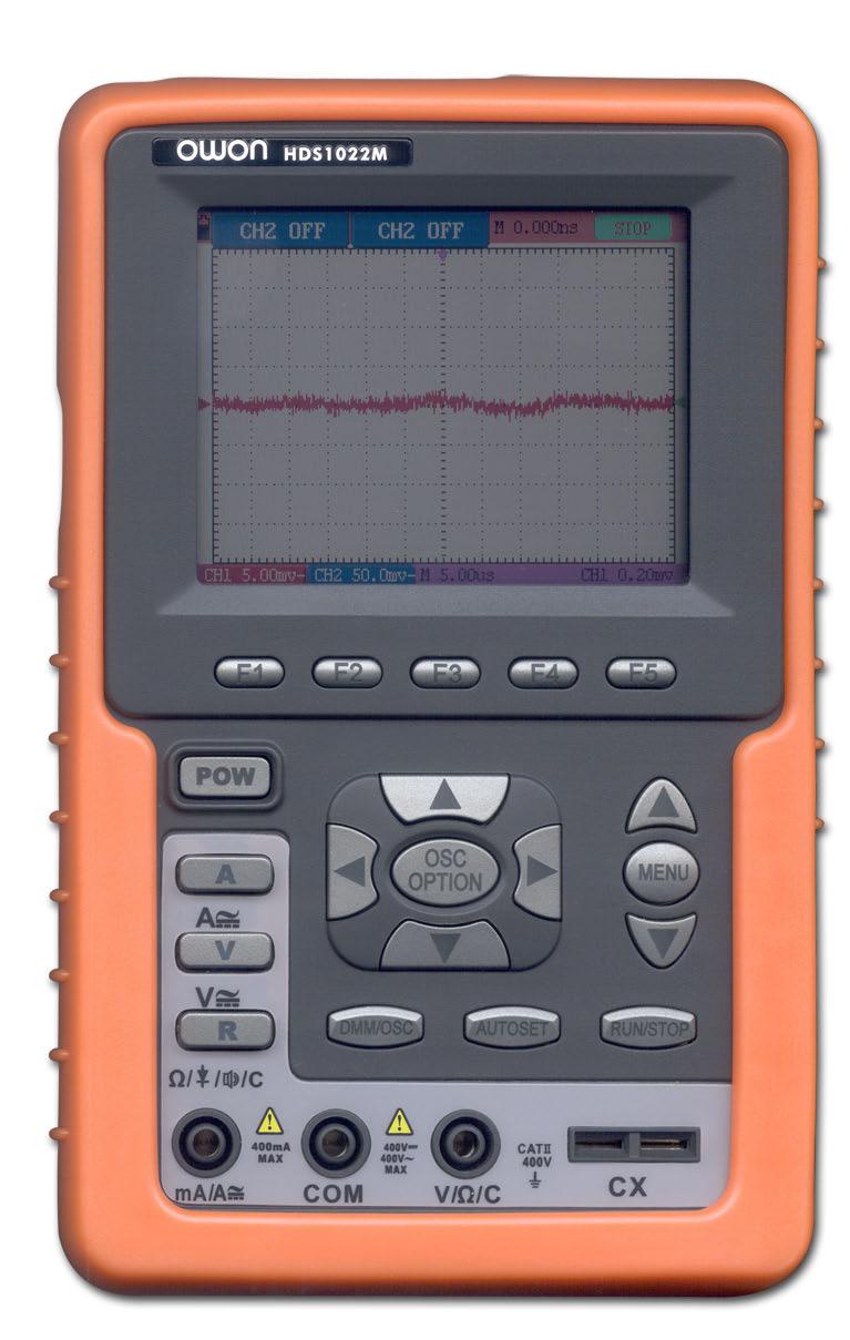
10 Safety Information 1.5. Description for Front Panel and Keys See the following figure 2: Description: Figure 2 1. Power adapter jack 2. Serial port 3. USB jack 4. Backlight switch 9
11 Safety Information 5. POWER: Power switch 6. A: Multimeter current measurement key 7. V: Multimeter voltage measurement key 8. R: Multimeter resistance, triode, On/Off and capacitance measurement key 9. OSC LEFT: Oscilloscope left-direction adjustment key 10. OSC RIGHT: Oscilloscope right-direction adjustment key 11. OSC OPTION: Oscilloscope setting key. With the combination application of the four keys OSC LEFT, OSC RIGHT, OSC UP and OSC DOWN, the users can make the following settings circularly by pressing OSC OPTION. The settings include: Voltage Unit Scale of Channel 1 (CH1 VOL); Voltage Unit Scale of Channel 2 (CH2 VOL); Primary Timebase (TIME BASE), zero point position of channel 1(CH1 ZERO), zero point position of channel 2(CH2 ZERO), trigger horizontal position (TIME) and trigger level position (TRIG). When performing Waveform Calculation, the users can also adjust and calculate the Display Multiplying Factor of waveform (CHM VOL) and the vertical display position (CHM ZERO). In cursor measurement mode, the users can adjust the positions of Cursor 1 (V1 or T1) and Cursor 2 (V2 or T2). 12. OSC DOWN: Oscilloscope display downward adjustment key. 13. OSC UP: Oscilloscope display upward adjustment key 14. OSC/DMM: Operation mode switching key between oscilloscope and multimeter 15. AUTO SET: Under the Multimeter Mode, when performing the current or voltage measurement, you can make a measurement switch between AC and DC with this key pressed; when performing the resistance measurement, you can select resistance, diode, On/Off or capacitance measurement circularly with this key. While this key is used for auto setting under the oscilloscope operation mode. 16. RUN/STOP: key for running or stopping the operation. 17. MENU DOWN: Choose the lower item on the menu list. 18. MENU: Show / Hide the menu 19. MENU UP: Choose the upper item on the menu list. 20. F1F5: Switch or Adjust options for each menu. 10
12 Using the Multimeter 2. Using The Scope 2.1. About this Chapter This chapter provides a step-by-step introduction to the scope functions. The introduction does not cover all of the capabilities of the scope functions but gives basic examples to show how to use the menus and perform basic operations Power-Up the oscilloscope Connect oscilloscope to AC power via a power adapter as shown in Figure 1. (The oscilloscope may still work with built-in Li-ion battery even without AC power supply) Turn the oscilloscope on by pressing down the power on/off key POW. The instrument then performs Selfchecking after power on. A greeting window and a sentence press any key to continue will display on the screen when the system finishes selfchecking. The users can press any key to enter the measuring function. The oscilloscope is powered up in its last setup configuration Oscilloscope Operation Window See the following figure 3: 11

13 Using the Multimeter Description Figure 3: Oscilloscope Operation Window 1. Battery electric quantity indicating symbols, including, and. 2. Auto measurement window 1, in which f means frequency, T means cycle, V means the average value, Vp the peak-peak value and Vk the root-mean-square value. 3. Auto measurement window The pointer indicates the horizontal triggering position. 5. This reading gives the Time Difference between the horizontal triggering position and the screen centerline. It reads zero when the pointer is in the center of the screen. 6. The trigger state indicates the following information. Auto: The oscilloscope is working in the automatic mode and displaying the waveform under the non-trigger state. Trig d: The oscilloscope has detected a trigger and collecting the information generated after the trigger. Ready: All pre-triggered data have been captured and the oscilloscope has been ready to receive trigger signals. Scan: The oscilloscope can gather and display the waveform data continuously in scanning 12
14 Using the Multimeter mode. Stop: The oscilloscope has stopped collecting the waveform data. 7. The green pointer shows the trigger voltage level. 8. A hidden-style menu: With the MENU key pressed, you can view or hide the menu. 9. Menu setting options: There are different setting options for different menus. 10. It reads the value of trigger voltage level. 11. The display shows the trigger signal source. 12. The reading gives the value of primary time base. 13. These graphics present the coupling modes of channel 2(CH2). The graphic indicates AC, the graphic indicates DC. 14. This reading shows the vertical Voltage Unit Scale of CH These graphics show the coupling mode of CH1, among which the graphic express indicates AC, the graphic indicates DC. 16. This reading shows the vertical Voltage Unit Scale of CH The blue pointer gives the grounding datum point of the waveform on CH2, which is the zero position of CH2. No display of this pointer indicates that the channel has not been opened. 18. OSC OPTION operation prompt: There are different prompts for different OSC OPTION operations. 19. The red pointer gives the grounding datum point of the waveform on CH1, which is the zero position of CH1. No display of this pointer indicates that the channel has not been opened. 20. Waveform display area. Red waveform represent CH1, blue waveform represent CH Navigating a Menu The following example shows how to use the tool s menus to select a function, as shown in the following figure. 1. Press the MENU key to display the Function Menu on the right of the screen and the corresponding optional settings on the bottom. Press MENU again will hide the Function Menu. 2. Press the MENU UP or MENU DOWN key to select different function menus. 3. Choose one key from F1 to F5 and press it to change function setting. See the following figure 4: 13
15 Using the Multimeter Figure 4: the tool s menus 2.5. Manually Setting the Vertical System, Horizontal System and Trigger Position With the combination application of the four keys OSC LEFT, OSC RIGHT, OSC UP and OSC DOWN, the users can make the following settings circularly by pressing OSC OPTION. The settings include: Voltage Unit Scale of Channel 1 (CH1 VOL); Voltage Unit Scale of Channel 2 (CH2 VOL); Primary Timebase (TIME BASE), zero point position of channel 1(CH1 ZERO), zero point position of channel 2(CH2 ZERO), trigger horizontal position (TIME) and trigger level position (TRIG). The following example shows how to use OSC OPTION key to make a setting. 1. Press once the OSC OPTION key; the following is displayed at the bottom left side of the screen, as shown in the figure below. LEFT/RIGHT Time Base UP/DOWN CH1 Vol See the following figure 5: 14


16 Using the Multimeter Figure 5: Voltage Unit Scale of Channel 1 2. Press the key OSC UP or OSC DOWN to adjust the vertical scale of Channel 1 and press OSC LIFT OSC RIGHT to adjust the horizontal time scale. 3. Press OSC OPTION once again, the following display is visible at bottom left side of the screen, as shown in the following figure: LEFT/RIGHT Time Base UP/DOWN CH2 Vol See the following figure 6: Figure 6: Voltage Unit Scale of Channel 2 4. Press the OSC UP or OSC DOWN key to adjust the vertical scale of Channel 2 and press 15

17 Using the Multimeter the OSC LIFT OSC RIGHT key to adjust the horizontal time scale. 5. Press the OSC OPTION key one more time, and the following display is visible at the bottom left side of the screen, shown as the following figure. LEFT/RIGHT Time UP/DOWN CH1 Zero See the following figure 7: Figure 7: zero point position of channel 1 6. Press OSC UP or OSC DOWN key to adjust the zero position of Channel 1 in vertical direction and press LIFT OSC RIGHT key to adjust the horizontal position. 7. Again, press OSC OPTION key and the following appears at the bottom left side of the screen, shown as the following figure, LEFT/RIGHT Time UP/DOWN CH2 Zero See the following figure 8: 16

18 Using the Multimeter Figure 8: zero point position of channel 2 8. Press the OSC UP or OSC DOWN key to adjust the zero position of Channel 2 in the vertical direction and press OSC LIFT OSC RIGHT key to adjust the horizontal position. 9. Press OSC OPTION key once more and the following appears at the bottom left of the screen, shown as the following figure. LEFT/RIGHT Time UP/DOWN Trig See the following figure 9: Figure 9: trigger level position 10. Press the OSC UP or OSC DOWN key to adjust the trigger position of Channel 2 and 17
19 Using the Multimeter press OSC LIFT OSC RIGHT key to adjust the horizontal position. 11. Press the OSC OPTION key again and return back to step 1. Term interpretation Vertical scale factor: It stands for the voltage amplitude represented by a division in the vertical direction of the display area, through the adjustment of which you can amplify or attenuate the signal and thus regulate the signal amplitude into the expected measurement range. Vertical zero position: It is referred to as the grounding datum point, through the adjustment of which you can regulate the display position of the waveform on the screen. Primary time base: It means the time values represented by a division in the horizontal direction of the display area. Trigger horizontal position: It means the time deviation between the actual trigger point and the screen central line, which will be displayed as 0 at the center point of the screen. Trigger level position: It represents the voltage deviation between the actual trigger level and the zero position of the triggering signal source channel Resetting the Oscilloscope If you want to reset the Oscilloscope to the factory settings, do the following: 1. Press MENU key and the function menu appears on the right side of the screen 2. Press the MENU UP or MENU DOWN key to select function setting and three options are visible at the bottom of the screen. 3. Press F1 key to select the factory settings. The oscilloscope is set to be the factory settings. See the following figure 10: 18
 for scope measurements, three safety 4-mm banana jack inputs for Multimeter R, V and A measurements, and two")
20 Using the Multimeter Figure 10: reset the Oscilloscope 2.7. Input Connections See figure 1: Look at the bottom and the right of the Oscilloscope. The Oscilloscope has seven signal inputs: two safety BNC jack inputs (CH1 and CH2) for scope measurements, three safety 4-mm banana jack inputs for Multimeter R, V and A measurements, and two quadratic jack inputs for Multimeter capacitance measurements. Isolated input allows independent floating measurements between Multimeters and Scopes Displaying an Unknown Signal with Auto Set The Auto-Set feature lets the Oscilloscope display and measure unknown signals automatically. This function optimizes the position, range, time base and triggering and assures a stable display of virtually any waveform.. This feature is especially useful for quickly checking several signals. To enable the Auto-Set feature, do the following: 1. Connect the test probe to the tested signals. 2. Press the AUTO SET key and the Oscilloscope is under the automatic measurement condition. The tested signals appear on the screen. 19
21 Using the Multimeter 2.9. Automatic zero-returning of trigger horizontal position and trigger level position When we adjust the trigger horizontal position and trigger level position to be maximal to make it off the screen center remotely, then we perform the following steps to make trigger horizontal position and trigger level position return to zero automatically. 1. Press OSD LEFT key and OSD RIGHT key simultaneously, the trigger horizontal position automatically returns to zero. 2. Press OSD UP and OSD DOWN button simultaneously, the trigger level position automatically returns to zero Automatic Measurements The Oscilloscope offers 5 ranges of automatic scope measurements. Your can display two numeric readings: measurement 1 and measurement 2. These readings are selectable independently, and the measurements can be done on the input CH1 or input CH2 waveform. To choose a frequency for CHI1, do the following: 1. Press MENU key and the function menu appear on the right side of the screen. 2. Press MENU UP or MENU DOWN key to select measurement 1. Five items selectable are visible at the bottom of the screen. 3. Press F1 key and select Freq CH1 from the mean square root value item. The measurement 1 window turns its color into red and shows the frequency for input CHI. To choose a Peak-Peak measurement for Input CH2, do the following: 1. Press MENU key and the function menu is displayed on the right side of the screen. 2. Press MENU UP or MENU DOWN key and select Measurement 2, with 5 items selectable displayed at the bottom of the screen. 3. Press F4 key to select PK-PK CH2 from Peak-Peak item. The measurement 2 window turns its color to be blue and shows the peak-peak value for input CH2. See the following figure 11: 20

22 Using the Multimeter Figure 11: automatic scope measurements Freezing the Screen You can freeze the screen (all readings and waveforms) 1. Press the RUN/STOP key to freeze the screen and STOP appears at top right side of the screen. 2. Press the RUN/STOP key once more to resume your measurement. See the following figure 12: Figure 12: freezing the screen 21

23 Using the Multimeter Using Average for Smoothing Waveforms To smooth the waveform, do the following: 1. Press the MENU key and the function menu appears on the right side of the screen. 2. Press MENU UP or MENU DOWN key to select ACQU mode, with four items selectable displayed at the bottom of the screen. 3. Press the F3 key to select Average Factors; then, press F4 key to jump to Averaging 32 item. This averages the outcomes of 32 acquisitions and shows the final averaging result on the screen, shown as the following figures. See the following figure 13: Figure 13: Average factor sampling mode Using Persistence to Display Waveforms You can use Persistence to observe dynamic signals. 1. Press MENU key and the function menu appears on the right side of the screen. 2. Press MENU UP or MENU DOWN key to select DISP SET. Four items selectable are displayed at the bottom of the screen. 3. Press F2 key to select Persist 1 sec, 2 sec, and 5 sec, infinite or close. In this case, jump to Infinite and the observed dynamic is kept on the screen continuously. When the item Close is selected, the Persistence function is closed. Look at the display, a screen like the following figure 14 can be shown. 22

24 Using the Multimeter Figure 14: Persistence to observe dynamic signals Using Peak Detection to Display Glitches You can use this function to display events (glitches or other asynchronous waveforms) of 50 ns or wider. 1. Press MENU key and the function menu appears at the right side of the screen. 2. Press MENU UP or MENU DOWN key to select the ACQU MODE. Four items selectable are displayed at the bottom of the screen. 3. Press F3 key and jump to Glitch Detect. In this case, you can test the glitch. Now, you can see a screen that looks like the following figure
25 Using the Multimeter Figure 15: Peak Detection Term interpretation Collecting mode: The oscilloscope transforms the collected analog data into a digital form after they are gathered in the following three different mode, that is, sampling, peak value detection and averaging values. Sampling: The oscilloscope takes samples from the signal at a equal time interval to reconstruct the waveform in this mode, by which the analog signal can be expressed correctly in most cases, yet, the rapid changes can not be collected between two sampling time intervals, causing the confusion and loss the narrow pulse in the signal probably. Peak value detection: The oscilloscope takes samples from the maximum and minimum of signals in each sampling interval and shows the waveform with the sampled data in this mode, thus, by which the oscilloscope may collect the possibly lost narrow pulse in the sampling mode but the noise is obvious. Averaging values: the oscilloscope collects several waveforms and average over them, and displays the averaged waveform in this mode, by which the random noise can be reduced. Duration time: When a new waveform is displayed, the previous waveform shown on the screen does not disappear immediately only to be displayed for a period of time, that is, the duration time, by setting which, the waveform can be displayed more continuously and thus a display similar to that shown by the analog oscilloscope can be achieved. Roll scan mode: The oscilloscope updates the waveform sampling points by scrolling display through a screen from left to right in this mode, which is only applicable to the primary time base setting of above 50ms Selecting AC-Coupling After a reset, the Oscilloscope is dc-coupled so that ac and dc voltages appear on the screen, Use ac-coupling when you wish to observe a small ac signal that rides on a dc signal. To select ac-coupling, do the following: 1. Press MENU key and the function menu appears at the right side of the screen. 2. Press MENU UP or MENU DOWN key to select the CH1 Setting. Four items selectable are visible at the bottom of the screen. 3. Press the F1 key and jump to AC. The bottom left side of the screen displays the ac-coupling icon. Now, you can see a screen that looks like the following figure
26 Using the Multimeter Figure 16: ac-coupling Reversing the Polarity of the Displayed Waveform To invert the input CH1 waveform, do the following: 1. Press the MENU key and the function menu appears at the right side of the screen. 2. Press the MENU UP or MENU DOWN key to select CH1 setting. Four items selectable are displayed at the bottom of the screen. 3. Press F4 key to jump to Inverted. The inverted waveform of CHI1 is displayed on the screen. Now, you can see a screen that looks like the following figure
27 Using the Multimeter Figure 17: inverted on Using Waveform Mathematics Functions When adding (CH1 + CH2), subtracting (CH1 CH2, CH2-CH1), multiplying (CH1 * CH2) or dividing CH1 / CH2 the input waveforms of CHI and CH2, the Oscilloscope will display the mathematical result waveform M and the input waveforms of CH1 and CH2 on the screen. The Mathematics functions perform a point-to-point calculation on the waveforms CH1 and CH2. To use a Mathematics function, do the following: 1. Press the MENU key and the function menu is displayed at the right side of the screen. 2. Press the MENU UP or MENU DOWN key to select the Waveform Calculation. Five items selectable appears at the bottom of the screen. 3. Press F3 key to select CH1+CH2 and the calculated waveform M (green) appears on the screen. Again, press the F3 key to close Waveform Calculation. 4. In this case, press the OSC OPTION key and the following is visible at the bottom left side of the screen. LEFT/RIGHT Time UP/DOWN CHM Zero Then, press the OSC UP or OSC DOWN key to adjust the vertical position of the calculated waveform M displayed on the screen. 5. Press the OSC OPTION key and the following appears at the bottom left side of the screen. LEFT/RIGHT Time Base UP/DOWN CHM Vol 26
28 Using the Multimeter Press the OSC UP or OSC DOWN key to adjust the displayed amplitude of the calculated waveform M. Now, you can see a screen that looks like the following figure 18. Figure 18: waveform mathematics 3. Using The Multimeter 3.1. About this chapter This chapter provides a step-by-step introduction to the multi-meter functions of the test tool (hereafter. The introduction gives basic examples to show how to use the menus and perform basic operations Making Meter Connections Use the three 4-mm safety banana jack inputs for the Meter functions: COM, V/Ω, ma. Two quadratic capacitance jacks: CX See figure 1 for the connections: 27

29 Using the Multimeter 3.3. Multimeter Operation Window Description 1. Battery electric quantity indictor. 2. Manual/Auto range indictors, among which the MANAL means measuring range in manual operation mode and Auto refers to the measuring range in automatic operation mode. 3. Measurement mode indicators: DCV: Direct voltage measurement ACV: Alternating voltage measurement DCA: Direct current measurement ACA: Alternating current measurement R: Resistance measurement : Diode measurement : On/Off measurement C: Capacitance measurement 4. The relative magnitude measurement indicator. 5. Running state indicators, among which RUN expresses continuous update and STOP 28
30 Using the Multimeter represents the screen locking. 6. The reference value of the relative magnitude measurement. 7. The multiplying power of the dial indication. To multiply the reading of dial pointer by multiplying power will get the measurement result. 8. The mail reading of measurement 9. Automatic control measuring range. 10. Absolute/ relative magnitude measuring control: The sign expresses the absolute magnitude measuring control and represents the relative magnitude measuring control. Manually measuring range control. 11. Manual measurement control. 12. The pointer indication of current/voltage: the green is cathode, the red is anode Making Multimeter Measurements Press DMM/OSC key, the oscilloscope will switch to the multimeter measure, the screen will display the multimeter windows, at the same time, prompt to correctly insert testing pen of the multimeter, at this time, then press any key to enter into multimeter measure Measuring Resistance Values To measure a resistance, do the following: 1. Press the R key and R appears at the top of the screen. 2. Insert the black lead into the COM banana jack input and the red lead into the V/Ω banana jack input. 3. Connect the red and black test leads to the resistor. The resistor value readings are shown on the screen in Ohm. Now, you can see a screen that looks like the following figure

31 Using the Multimeter Figure 20: measure resistance Making a Diode Measurement To make a measurement on the diode, do the following: 1. Press the R key and R appears at the top of the screen. 2. Press AUTO SET key once and the following is displayed on the screen. 3. Insert the black lead into the COM banana jack input and the red lead into the V/Ω banana jack input. 4. Connect the red and black leads to the resistor and the diode resistor readings are displayed on the screen in V. Now, you can see a screen that looks like the following figure
32 Using the Multimeter Figure 21: Diode Measurement On-off test To perform an On-off test, do the following: 1. Press the R key and R appears on the top of the screen. 2. Press the AUTO SET key three times and the following is shown on the screen. 3. Insert the black lead into the COM banana jack input and the red lead into the V/Ω banana jack input. 4. Connect the red and black leads to the test point. If the resistance value of the tested point is less than 50Ω, you will hear beep sound from the test tool. Now, you can see a screen that looks like the following figure
33 Using the Multimeter Figure 22: On-off test Making a Capacitance Measurement To measure a capacitance, do the following: 1. Press the R key and R appears on the top of the screen 2. Press the AUTO SET key four times and C appears at the top of the screen. 3. Insert the measured capacitance into the quadratic jack and the screen shows the capacitance reading. Notice: when measured value is less than 5 nf capacitance, please use small capacitance measurer of this multimeter and use relative value measuring mode to improve measuring precision. It will take about 30seconds if capacitance measurement is large than 40uF. Now, you can see a screen that looks like the following figure

34 Using the Multimeter Figure 23: Capacitance Measurement Making a DC voltage Measurement To measure a DC voltage, do the following: 1. Press the V key and DCV appears at the top of the screen. 2. Insert the black lead into the COM banana jack input and the red lead into the V/Ω banana jack input. 3. Connect the red and black leads to the measured point and the measured point voltage value is displayed on the screen. Now, you can see a screen that looks like the following figure

35 Using the Multimeter Figure 24: DC voltage Measurement Making a AC voltage Measurement To measure the AC voltage, do the following: 1. Press the V key and DCV appears at the top of the screen. 2. Press the AUTO SET key and ACV appears at the top of the screen. 3. Insert the black lead into the COM banana jack input and the red lead into the V/Ω banana jack input. 4. Connect the red and black leads to the measured points and the AC voltage values of measured points will be displayed on the screen. Look at the display; you can see a screen that looks like the following figure 25. Figure 25: AC voltage Measurement Making a DC current Measurement To measure a DC current which is less than 400 ma, do the following: 1. Press the A key and DCA appears at the top of the screen. The unit on the main reading screen is ma. ma and 20A will display on the right bottom of screen, press F4 or F5 to switch the measurement between Ma and 20A. 400mA is acquiescently. 2. Insert the black lead into the COM banana jack input and the red lead into the ma banana jack input. 3. Connect the red and black leads to the measured points and the DC current values of measured points will be displayed on the screen. 34
36 Using the Multimeter Look at the display; you can see a screen that looks like the following figure 26. Figure 26: DC current Measurement for 400 ma To measure a DC current which is larger than 400 ma, do the following: 1. Press the A key and DCA appears at the top of the screen. The unit on the main reading screen is ma. 2. Press F5 key change to 20A measurement, he unit on the main reading screen is A. 3. Plug current extended module in current measure jack, then plug the probe in the module 4. Connect the red and black leads to the measured point and the DC current value of the measured point will be displayed on the screen. 5. Press F4 return to 400 ma measure. Look at the display, you can see a screen that looks like the following figure
37 Using the Multimeter Figure 27: DC current Measurement for 20A Making an AC Current Measurement To measure an AC current which is less than 400 ma, do the following: 1. Press the A key and DCA appears at the top of the screen. The unit on the main reading screen is ma. ma and 20A will display on the right bottom of screen, press F4 or F5 to switch the measurement between Ma and 20A. 400mA is acquiescently. 2. Press the AUTO SET key once and ACA is visible at the top of the screen. 3. Insert the black lead into the COM banana jack input and the red lead into the ma banana jack input. 4. Connect the red and black leads to the measured point and the AC current value of the measured point will be displayed on the screen Look at the display; you can see a screen that looks like the following figure
38 Using the Multimeter Figure 28: AC current Measurement for 400 ma To measure an AC current which is larger than 400 ma, do the following: 1. Press the AUTO SET key once and ACA is visible at the top of the screen. 2. Press F5 to select 20A measure, the unit of main reading window is A. 3. Press the AUTO SET key once and ACA is visible at the top of the screen. 4. Plug current extended module in current measure jack, then plug the probe in the module. 5. Connect the red and black leads to the measured point and the AC current value of the measured point will be displayed on the screen. 6. Press F4 return to 400mA measure. Look at the display; you can see a screen that looks like the following figure
39 Using the Multimeter Figure 29: AC current Measurement for 20A 3.5. Freezing the Readings You can freeze the displayed readings at any time. 1. Press the RUN /STOP key to freeze the screen and STOP will be displayed at the top right of the screen. 2. Again, press the RUN /STOP key, you can resume your measurement. Look at the display; you can see a screen that looks like the following figure 30. Figure 30: Freezing the Readings 3.6. Taking a relative measurement A currently measured result relative to the defined reference value is displayed in a relative measurement. The following example shows how to take a relative measurement. At first, it is required to acquire a reference value. 1. Press V key and DCV is displayed on the top side of the screen. 2. Measure a voltage and take it as the reference value. 3. Press F2 key and is displayed on the top side of the screen. In this way, the reference value is saved as the reference in the following measurements. The saved reference value is displayed below. 4. Measure the voltage to be compared with the reference value. It can be observed that the displayed major reading is the difference between the actually measured result and the reference value. 38

40 Using the Multimeter Look at the display; you can see a screen that looks like the following figure 31. Figure 31: relative measurement 3.7. Selecting automatic/manual range adjustment The defaulted range mode of the instrument is automatic range. To switch to the manual range, perform the following steps: 1 Press F1 key and MANUAL is displayed on the top left side of the screen to enter the manual range mode. 2 Under the manual range mode, the measuring range is increased by a stage when pressing F1 key each time, and when reaching the highest stage, it jumps to the lowest stage by pressing F1 key once again. To multiply the reading of dial pointer by multiplying power and the unit of main reading on the screen will get the measurement result. 3 Press F3 key and AUTO is displayed on the top left side of the screen to switch back to the automatic range mode. Look at the display; you can see a screen that looks like the following figure

41 Using the Multimeter Figure 32: automatic/manual range adjustment 40

42 Advanced Function of Oscilloscope 4. Advanced Function of Oscilloscope 4.1. About this chapter This chapter will detail the oscilloscope function of the test tool Setting the Vertical CH1 and CH2 Each channel has its own independent vertical menu and each item can be set respectively based on the specific channel. To make vertical CH1 and CH2 settings, do the following: 1. Press the MENU key and the function menu appears at the right of the screen. 2. Press the MUNU UP or MENU DOWN key to jump to CH1 Setting and 4 options appears at the bottom of the screen. 3. Select and press key from F1 through F4 keys to make different settings. Now, you can find a screen that looks like the following figure 33: Figure 33: Setting the Vertical The following Table describes the Vertical Channel menu: Function menu Coupling Setting AC DC Description The dc component in the input signal is blocked.. The ac and dc components of the input signal are allowed. 41
43 Advanced Function of Oscilloscope Channel Probe Invert Close Open 1X 10X 100X 1000X Close Open Close the channel. Open a channel. Select one according the probe attenuation factor to ensure a correct vertical scale reading. Waveform is displayed normally. Open the Invert function of the waveform setting Setting the Channel Coupling With CH1 taken for example, the measured signal is a sine wave signal containing a dc offset. Press F1 Coupling first and then AC to make an ac coupling setting. The dc component contained in the tested signal is blocked. Press F1 Coupling first and then DC to make a dc coupling setting. Both dc and ac components contained in the tested signal are permitted. The waveform is displayed as the following figure 34, figure 35. Figure 34: AC coupling 42
44 Advanced Function of Oscilloscope Figure 35: DC coupling Make Open and Close Settings on Channel With CH1 taken for example, Press F2 Channel first, then Close to make a Close setting on CH1; Press F2 Channel key first, and then Open to make an Open setting on CH Adjusting the Probe Scale It is necessary to adjust the probe attenuation scale factor correspondingly in the channel operation menu in order to comply with the probe attenuation scale. If it is a 10:1 probe, the scale of the input channel of the oscilloscope should be selected as 10X to avoid any error occurring in the displayed scale factor information and tested data. Press F3 Probe to jump to the relative probe. Table: Probe attenuation factor and the corresponding menu setting Probe attenuation factor Corresponding Menu Setting 1:1 1X 10:1 10X 100:1 100X 1000:1 1000X Setting of Inverted Waveform Inverted waveform: The displayed signal reverses 180 degrees relatively to the ground 43
45 Advanced Function of Oscilloscope potential. Press F4 Invert to start Invert; again press F4 Invert to close Invert Make the MATH function menu Setting The MATH functions in showing the result of adding, subtracting, multiplying or dividing calculation on CH1 and CH2 channel waveforms. Also, the result of arithmetic operation can be measured with grid or cursor. The amplitude of the calculated waveform can be adjusted with CHM VOL, which is displayed in the scale factor form. The amplitude ranges from through 10 and steps in the form, that is, it can be expressed as 0.001X, 0.002X, 0.005X 10X. The position of the calculated waveform can be adjusted up and down with the CHM ZORE key used. The corresponding operation function table Setting CH1-CH2 CH2-CH1 CH1+CH2 CH1*CH2 CH1/CH2 Description CH1 waveform minus CH2 waveform. CH1 waveform minus CH2 waveform Add CH1 waveform into CH2 waveform. Multiply CH1 waveform and CH2 waveform. Divide CH1 waveform by CH2 waveform. To perform the CH1+CH2 waveform calculation, do the following: 1. Press the MENU key and the function menu appears at the right of the screen. 2. Press the MUNU UP or MENU DOWN key to select MATH and 5 options are displayed at the bottom of the screen. 3. Press the F3 CH1+CH2 key and the obtained waveform M appears on the screen. Again, press the F3 key and Close the waveform M. 4. Press the OSD OPTION key and the following is displayed on the screen: LEFT/RIGHT Time Base UP/DOWN CH1 Vol 5. Press the OSD UP or OSD DOWN key to adjust the amplitude of the waveform M. 6. Again, press the OSD OPTION key twice and the screen shows the following: LEFT/RIGHT Time UP/DOWN CHM Zero 7. Press the OSD UP or OSD DOWN key to adjust the position of the waveform M. Now, look at the display and you will find a screen that looks like the following figure36. 44

46 Advanced Function of Oscilloscope figure36: waveform mathematics 4.4. Setting the Trigger System The Trigger defines the time when the acquisition of data and display of waveform start. If it is set correctly, the trigger can turn an unstable display into a significant waveform. When starting the acquisition of data, the oscilloscope collects sufficient data to draw the waveform at the left side of the triggering point. With waiting for the triggering condition, the oscilloscope is gathering data continuously. After a trigger is detected, the oscilloscope gathers enough data continuously to draw the waveform at the right side of the triggering point. To make a trigger mode setting, do the following: 1. Press the MENU key and the function menu appears at the right of the screen. 2. Press the MUNU UP or MENU DOWN key to select TRIG MODE and five items selectable are displayed at the bottom of the screen. 3. Select and press one from F1 through F5 key to make a different setting. 4. Press the OSD OPTION key and the following is shown on the screen: LEFT/RIGHT Time UP/DOWN Trig 5. Press the OSD UP or OSD DOWN key to adjust the trigger level position. Now, look at the display: you can see a screen in the following figure37. 45

47 Advanced Function of Oscilloscope figure37. Edge triggering 4.5. Triggering Control There are two triggering modes including Edge triggering and Video triggering. Each trigger mode is set by different function menu. Edge triggering: It occurs when the trigger input passes through a given level along the specified direction. Video triggering: Perform video field trigger or line trigger on the standard video signals. The following describes the Edge triggering and Video triggering menus respectively. Edge triggering The Edge triggering is a mode by which trigger occurs at the triggering threshold value of the input signal edge. With the Edge triggering selected, the trigger happens on the rise or fall edge of the input signal, shown as the following figure. The Edge triggering menu is described in the following table. Function menu Settings Description Slope Rise Fall Triggering on the rise edge of the signal. Triggering on the fall edge of the signal. Signal source CH1 CH2 CH1 is used as the trigger source. CH2 is used as the trigger source. Trigger mode Auto Normal Acquisition of waveforms is possible even if there is no triggering condition detected. Acquisition of waveforms can only be done when the triggering condition is satisfied. 46

48 Advanced Function of Oscilloscope Coupling Single shot AC DC The sampling is performed on a waveform when one trigger is detected, and then stop sampling.. With this mode selected, the DC component is prevented from passing-though. All dc components are allowed. HF suppression The HF part of the signal is prohibited and only the HF component is allowed. Video triggering LF suppression The LF part of the signal is prohibited and only the LF component is allowed. With Video triggering selected, the oscilloscope performs the NTSC, PAL or SECAM standard video signals field or line trigger. Now, you can see a screen that looks like the following figure 38, figure 39: Figure 38: Video field trigger 47

49 Advanced Function of Oscilloscope Figure 39: Video line trigger The Video triggering menu is described in the following table Function menu Settings Description Polarity Normal Invert Applicable to the video signal in which the black level is of low level. Applicable to the video signal of which the black level is of high level. Signal source CH1 CH2 Select CH1 as the trigger source. Select CH2 as the trigger source. SYNC Line Field Make a video line trigger synchronization setting Make a video field trigger synchronization setting. Term interpretation Trigger modes: There are three kinds of trigger modes available for this oscilloscope that is, auto, normal and single shot. Automatic trigger mode: The oscilloscope can acquire the waveform without any triggering condition detected in this mode, in which it will be triggered compulsively when waiting for a specified period of time without any triggering condition ignited When an invalid trigger is enforcedthe oscilloscope can not keep the waveform in phase. Normal trigger mode: In this mode, the oscilloscope cannot acquire the waveform till it is triggered. When there is not any trigger, the oscilloscope will display the origin waveform without new waveforms captured. Single shot mode: In this mode, the oscilloscope will detect a trigger and capture a waveform at each time when the customer presses the RUN/STOP key. 48
50 Advanced Function of Oscilloscope 4.6. Acquiring Mode Setting The Acquiring Mode menu is described in the list shown as below: Function menu Settings Description Sampling Normal sampling mode. Peak Detection Used to detect the jamming glitch and reduce the possible blurring. Average value Used to reduce the random and unrelated noises. Several average factors are available for being selected. Average factor 4, 16, 64 Select the average factor. or Display Setting The Display Setting menu is described in the following table: Function menu Settings Description Type Vector Dot The vector is filled up spaces between neighboring sampling points in the display. Only sampling points are displayed. Persistence Close Setting persistence time for each sampling point. 1s 2s 5s Infinite Display format YT XY Display the relative relationship between vertical voltage and horizontal time. Display CH1 on the horizontal axis and CH2 on the vertical axis. Communication Bitmap Vector The data transmitted in communication are bitmaps. The data transmitted in communication are vectors Display Style The display style includes Vector and Dot displays, shown as the following figure 40, figure 41: 49

51 Advanced Function of Oscilloscope Figure 40: Dot style Figure 41: Vector style Persistence With Persistence function selected, the displayed saved original data gradually decay in color and the new data are bright in color; with infinite persistence mode selected, the recorded points will be kept on the screen till the controlled value is changed XY mode This mode is only applicable to CH1 and CH2. With the XY mode selected, CH1 is displayed on 50
52 Advanced Function of Oscilloscope the horizontal axis and CH2 is on the vertical axis; when the oscilloscope is under the sampling mode in which no trigger is found, the data appear in light spots. Operations for various control keys are shown as below: The CH1 VOL and CH1 ZORE for CH1 are used to set the horizontal scale and position. The CH2 VOL and CH2 ZORE for CH2 are used to set the vertical scale and position continuously. The following functions do not work in the XY display mode: Reference or digital value waveform Cursor Auto Setting Time base control Trigger control 4.8. Waveform Saving Setups The oscilloscope can save 4 waveforms, which can be displayed on the screen with the present waveform. The recalled waveform saved in the memory cannot be adjusted, The waveform saving /recalling menu is described in the following list: Function Setups Description menu Signal source CH1 Select the displayed waveform which you want to save. CH2 MATH Address A, B, C and D Select the address for saving or recalling a waveform. Saving Store the waveform of a selected signal source into the selected address. Addresses A, B, C and D Close Start Close or start displaying the waveforms stored in address A, B, C or D. To save a waveform on CH1 in address A, do the following: 1. Press the MENU key and the function menu appears at the right of the screen. 2. Press the MUNU UP or MENU DOWN key to select the Waveform Saving. Four items selectable are displayed at the bottom of the screen. 3. Press the F1 key to select the signal source CH1. 4. Press the F2 key to select the address A. 5. Press the F3 key to save the waveform on CHI1 in address A. 51

53 Advanced Function of Oscilloscope To display the saved waveform on the screen, do the following: 6. Press the F4 key to select Start for the address A. The waveform saved in address A will be displayed on the screen in green color. The display color is green, and the zero point of waveform k, voltage and time is purple Now, you can see a screen that looks like the following figure 42. figure 42Waveform Saving 4.9. Function Setting Menu The function setting menu is described in the following list: Function menu Setting Description Factory setting Resume the instrument to its factory settings. Self-correcting Perform the self-correcting procedure. LANGUAGE CHINESE Select the display language of the operation system. ENGLISH Self-correcting: The self-correcting program can improve the accuracy of the oscilloscope under the ambient temperature to the maximum. If the ambient temperature variation is equal to or larger than 5 Celsius degrees, the self-correcting program should be performed to gain the maximum accuracy. Before the self-correcting program is performed, the probe or lead should be disconnected with the input connector, then, select the F2 key Self-correcting item. After confirming that everything is ready, press the F2 key Self-correcting key and enter into the self-correcting program. 52
54 Advanced Function of Oscilloscope Making Automatic Measurements The oscilloscope can perform 5 types automatic measurements such as frequency, cycle, average value, peak-to-peak value and root mean square value. And gives two kinds of measurement results simultaneously on the screen, The function menu for automatic measurements is described in the following list: Function menu Settings Description Frequency CH1 CH2 Measure the frequency of CH1 Measure the frequency of CH2 Cycle CH1 CH2 Measure the cycle of CH1. Measure the cycle of CH1 Average value CH1 CH2 Measure the average value of CHI. Measure the average value of CH2. Peak-to-Peak value CH1 CH2 Measure the peak-to-peak value of CH1. Measure the peak-to-peak value of CH2. RMS value CH1 CH2 Measure root mean square (RMS) value of CH1. Measure root mean square (RMS) value of CH2. To measure the frequency of CH1 with Measurement 1 and the frequency of CH2 with Measurement 2, do the following: 1. Press the MENU key and the function menu is shown at the right of the screen. 2. Press the MUNU UP or MENU DOWN key to select Measurement 1. Five options appear at the bottom of the screen. 3. Press the F1 key to select the frequency measurement as CH1. The measurement window 1 on the screen turns into one red in color and shows the frequency of CH1. 4. Press the MUNU UP or MENU DOWN key to select Measurement 2. Five options appear at the bottom of the screen. 5. Press the F4 key to jump to the peak-to-peak measurement as CH2. The measurement window on the screen turns into one blue in color and shows the peak-to-peak value of CH2. Now, you can see a screen that looks like the following figure 43: 53
55 Advanced Function of Oscilloscope Figure 43: automatic measurements Setting the Cursor Measurements This oscilloscope allows you to make manual cursor measurements on time and voltage. The signal sources include Channel 1(CH1), Channel 2 (CH2), MATH, storage address A and storage address B. The cursor measurement menus are listed and described in the following table: Function menus Settings Description Type Close Voltage Time Close the cursor measurement. Display the voltage measurement cursor and menu. Display the time measurement cursor and menu. Signal sources CH1, CH2, ATH, address A and address B. Select the waveform channel on which the cursor measurement will be performed. To make a voltage measurement on CH1, doing the following: 1. Press the MENU key and the function menus are displayed at the right of the screen. 2. Press the MUNU UP or MENU DOWN key to select Cursor Measurement. Two options are shown at the bottom of the screen. 3. Press F1 key to select the measurement type Voltage. Two purple crossing dashed lines V1 and V2 are shown on the screen. 4. Press the F2 key to select the measured channel CH1. 5. Press and hold the OSD OPTION key till the UP/DOWN CURSOR V1 is visible on the screen. At this time, adjust OSE UP or OSD DOWN and you can see that the dashed line V1 54
56 Advanced Function of Oscilloscope is moving up and down while the measured voltage value of V1 relative to the zero position of CH1 appears on the screen. 6. Press and hold the OSD OPTION key till UP/DOWN CURSOR V2 appears on the screen. Now, adjust the OSE UP or OSD DOWN and you can observe the dashed line V2 moving up and down while the measured voltage value of V2 relative to the zero position of CH1 is displayed on the screen. Also, the absolute values of V1 and V2 can be shown on the screen. Now, you can see a screen that looks like the following figure 44. Figure 44: use the cursor for a voltage measurement To use the cursor for a time measurement on CH1, do the following: 1. Press the MENU key and the function menus are displayed at the right of the screen. 2. Press the MUNU UP or MENU DOWN key to select Cursor measurement key. Two key labels selectable are shown at the bottom of the screen. 3. Press the F1 key to the measurement type Time. Two vertical dashed lines T1 and T2 appear on the screen. 4. Press the F2 key and jump to the measured channel CH1. 5. Press and hold the OSD OPTION key till the UP/DOWN CURSOR T1 appears on the screen. Then, adjust the OSE UP or OSD DOWN and you can observe the dashed line moving left and right. At the same time, the time value of T1 relative to the screen middle point position will be displayed on the screen. 6. Keep pressing on the OSD OPTION key till the UP/DOWN CURSOR T2 is displayed on the screen. Then, adjust the OSE UP or OSD DOWN and you can find that the dashed line T2 is moving right and left while the time value of T1 relative to the screen middle point position appears on the screen. You can also observe the absolute time values and frequencies of T1 and T2. 55
57 Advanced Function of Oscilloscope Now, you can see a screen that looks like the following figure 45. Figure 45: use the cursor for a time measurement System State Menu: The system state menu is used to display information about the present horizontal system, vertical system, trigger system and others. The operation steps are shown as below. 1. Press the MENU key and the function menu is displayed at the right of the screen. 2. Press the MUNU UP or MENU DOWN key to select the System State. Four options appear at the bottom of the screen. 3. Sequentially press key F1 through F4 key and the corresponding state information will be shown on the screen. The screen that looks like the following figure 46 will be displayed. 56

58 Advanced Function of Oscilloscope Figure 46: System State Setting of time base mode The time base mode menu is explained as the following table Function menu Setting Explanation Main time base Window setting Window extension Horizontal main time base is used to wave display Use two cursors to define a window area Expand the defined window to full-screen display For the operation of window extension, please execute the following steps: 1. Press MENU key, display the function menu on the right side of the screen. 2. Press MENU UP or MENU DOWN key to select time base mode, display three options at the bottom. 3. Press F2 key to select window setting. 4. Press OSC OPTION key, pop up TIME BASE, at this time, then press OSC LEFT and OSC RIGHT key to adjust the time base window area defined by two cursors, the window size will vary. 5. Press OSC OPTION key and call TIME, at this time, press OSC LEFT and OSC RIGHT to adjust the window position defined by two cursors, the window position is the time difference of the window center to main time base s horizontal pointer. 6. Press F3 key, select window extension, the defined window extends into the full-screen display. The screen that looks like the following figure 47, 48 will be displayed. 57


59 Advanced Function of Oscilloscope Figure 47: window setting Figure 48: window extension Data transmission The oscilloscope can take use of the HyperTerminal in WINDOWS operating system to transmit the currently displayed waveform through a serial-port into a computer for saving in form of bitmap. To realize data transmission, perform the following steps: 1 Set the HyperTerminal in WINDOWS. Select Start Program Accessory Communication Hyperterminal, input Connection name, select Connect port and set transmission data rate as , data bit as 8 bits, even-odd check as none, stop bit as 1 and data flow control as none. 2 Use a serial-port line to connect the oscilloscope and the computer 3 Open HyperTerminal, select Transmit first and then Receive files, set saving path, set 58
OWON HDS2062M Handheld Digital Storage Oscilloscope & Multimeter User s Manual
 OWON HDS2062M Handheld Digital Storage Oscilloscope & Multimeter User s Manual 1 LIMITED WARRANTY & LIMITATON OF LIABILITY Each OWON product is warranted to be free from defects in material and workmanship
OS-1022 Handheld Digital Storage. Oscilloscope & Multimeter. User Manual
 OS-1022 Handheld Digital Storage Oscilloscope & Multimeter User Manual General Warranty We warrants that the product will be free from defects in materials and workmanship for a period of three years from
OS Series Handheld Digital Storage. Oscilloscope & Multimeter. User Manual
 OS Series Handheld Digital Storage Oscilloscope & Multimeter User Manual OS-1022 OS-2062 20MHz 60 MHz General Warranty We warrants that the product will be free from defects in materials and workmanship
Model P2016. Dual Channel Handheld Digital Storage. Oscilloscope & Multimeter. Quick Scope Guide
 Model P2016 Dual Channel Handheld Digital Storage Oscilloscope & Multimeter Quick Scope Guide General Warranty BNC warrants that the product will be free from defects in materials and workmanship for 3
OWON. HDS2062M-N Handheld Digital Storage Oscilloscope & Multimeter User s Manual
 OWON HDS2062M-N Handheld Digital Storage Oscilloscope & Multimeter User s Manual WWW.OWON.COM.CN 1 WARRANTY Lilliput warrants that this OWON brand product will be free from defects in materials and workmanship
72-8 Series Handheld Digital Storage. Oscilloscope & Multimeter. User Manual
 72-8 Series Handheld Digital Storage Oscilloscope & Multimeter User Manual 72-8470 72-8474 www.tenma.com 1 WARRANTY Tenma Test Equipment warrants that this product will be free from defects in materials
PeakTech 1195 / Operation manual. Digital Storage Oscilloscopes/DMM
 PeakTech 1195 / 1205 Operation manual Digital Storage Oscilloscopes/DMM Package Contents (see the picture below) Description 1. PeakTech 1195/1205 incl. Accu 2. Power Adaptor 3. Oscilloscope Probes 4.
HDS-N Dual Channel Series Handheld Digital Storage. Oscilloscope & Multimeter. User Manual
 HDS-N Dual Channel Series Handheld Digital Storage Oscilloscope & Multimeter User Manual HDS1022M-N HDS1022M-I HDS2062M-N HDS3102M-N HDS4202M-N Note: "I" indicates that the two channels are isolated electrically.
Model P2016. Dual Channel Handheld Digital Storage. Oscilloscope & Multimeter. User Manual
 Model P2016 Dual Channel Handheld Digital Storage Oscilloscope & Multimeter User Manual April 2018 Edition, Version 1.6.3BNC Copyright. All rights reserved. The Berkeley Nucleonics products are under the
HDS1021M Handheld Digital Storage. Oscilloscope & Multimeter. User Manual
 HDS1021M Handheld Digital Storage Oscilloscope & Multimeter User Manual WWW.OWON.COM.CN Dec. 2009 edition Copy Right in this Manual Lilliput Company. All rights have been reserved. The Lilliput s products
Quick Start. RSHS1000 Series Handheld Digital Oscilloscope
 Quick Start RSHS1000 Series Handheld Digital Oscilloscope General Safety Summary Carefully read the following safety precautions to avoid personal injury and prevent damage to the instrument or any products
Quick Start. SHS1000 Series Handheld Digital Oscilloscope QS03010-E02B 2015 SIGLENT TECHNOLOGIES CO., LTD
 Quick Start SHS1000 Series Handheld Digital Oscilloscope QS03010-E02B 2015 SIGLENT TECHNOLOGIES CO., LTD Guaranty and Declaration Copyright SIGLENT TECHNOLOGIES CO., LTD. All Rights Reserved. Trademark
Digital Storage Oscilloscopes 2550 Series
 Data Sheet Digital Storage Oscilloscopes 2550 Series The 2550 series digital storage oscilloscopes provide high performance and value in 2-channel and 4-channel configurations. With bandwidth from 70 MHz
Burlington County College INSTRUCTION GUIDE. for the. Hewlett Packard. FUNCTION GENERATOR Model #33120A. and. Tektronix
 v1.2 Burlington County College INSTRUCTION GUIDE for the Hewlett Packard FUNCTION GENERATOR Model #33120A and Tektronix OSCILLOSCOPE Model #MSO2004B Summer 2014 Pg. 2 Scope-Gen Handout_pgs1-8_v1.2_SU14.doc
Tablet Oscilloscope Quick Guide
 Tablet Oscilloscope Quick Guide For tbook Series Shenzhen Micsig Instruments Co., Ltd. Copyright Copyright Shenzhen Micsig Instruments Co., Ltd. All Rights Reserved. Version Version: MKX2014-001; Product
Fluke 196C/199C. ScopeMeter. Users Manual
 Fluke 196C/199C ScopeMeter Users Manual 4822 872 30482 October 2001 2001 Fluke Corporation. All rights reserved. Printed in the Netherlands. All product names are trademarks of their respective companies.
Fluke /
 Fluke 190-104/190-204 ScopeMeter 190 Series II Service Manual PN 4822 872 05405 March 2011 2011 Fluke Corporation, All rights reserved. Printed in the Netherlands All product names are trademarks of their
User Manual. Digital Storage Oscilloscopes Models 2534, 2540 & 2542
 User Manual Digital Storage Oscilloscopes Models 2534, 2540 & 2542 General Safety Summary General Safety Summary Review the following safety precautions to avoid injury and prevent damage to this product
User Manual. Digital Storage Oscilloscopes Models 2534, 2540 & General Safety Summary. Version 1.03
 General Safety Summary General Safety Summary User Manual Digital Storage Oscilloscopes Models 2534, 2540 & 2542 Review the following safety precautions to avoid injury and prevent damage to this product
2510 Series Handheld Digital Storage Oscilloscopes
 Model: 2511, 2512, 2515, 2516 2510 Series Handheld Digital Storage Oscilloscopes USER MANUAL Safety Summary The following safety precautions apply to both operating and maintenance personnel and must be
ScopeMeter 190 Series Specifications
 Seite 1 von 7 ScopeMeter 190 Series Specifications Product Home Features Specifications Models, Options & Accessories Oscilloscope Mode Meter Mode Recorder Mode General Specifications Oscilloscope Mode
Agilent DSO5014A Oscilloscope Tutorial
 Contents UNIVERSITY OF CALIFORNIA AT BERKELEY College of Engineering Department of Electrical Engineering and Computer Sciences EE105 Lab Experiments Agilent DSO5014A Oscilloscope Tutorial 1 Introduction
Oscilloscope Guide Tektronix TDS3034B & TDS3052B
 Tektronix TDS3034B & TDS3052B Version 2008-Jan-1 Dept. of Electrical & Computer Engineering Portland State University Copyright 2008 Portland State University 1 Basic Information This guide provides basic
Electrical and Electronic Laboratory Faculty of Engineering Chulalongkorn University. Cathode-Ray Oscilloscope (CRO)
") 2141274 Electrical and Electronic Laboratory Faculty of Engineering Chulalongkorn University Cathode-Ray Oscilloscope (CRO) Objectives You will be able to use an oscilloscope to measure voltage, frequency
2141274 Electrical and Electronic Laboratory Faculty of Engineering Chulalongkorn University Cathode-Ray Oscilloscope (CRO) Objectives You will be able to use an oscilloscope to measure voltage, frequency
4CH/2CH Digital Storage Oscilloscopes
 Model: 2553, 2555, 2556, 2557, 2558, 2559 4CH/2CH Digital Storage Oscilloscopes USER MANUAL Safety Summary The following safety precautions apply to both operating and maintenance personnel and must be
S op o e p C on o t n rol o s L arni n n i g n g O bj b e j ctiv i e v s
 ET 150 Scope Controls Learning Objectives In this lesson you will: learn the location and function of oscilloscope controls. see block diagrams of analog and digital oscilloscopes. see how different input
INSTRUCTIONAL MANUAL FOR LCD ZOOM MICROSCOPE
 INSTRUCTIONAL MANUAL FOR LCD ZOOM MICROSCOPE ? 8 LCD Screen? 10.4 LCD Screen LCD Zoom Microscope Instruction Manual Please read the Instruction Manual carefully before installation and keep it for future
TDS Series. User Manual
 99 Washington Street Melrose, MA 02176 Phone 781-665-1400 Toll Free 1-800-517-8431 Visit us at www.testequipmentdepot.com TDS Series Touchscreen Digital Storage Oscilloscopes User Manual TDS7104 TDS8104
25 MHz Digital Storage Oscilloscope
 99 Washington Street Melrose, MA 02176 Phone 781-665-1400 Toll Free 1-800-517-8431 Visit us at www.testequipmentdepot.com Model: 2530B 25 MHz Digital Storage Oscilloscope USER MANUAL Safety Summary The
LeCroy Digital Oscilloscopes
 LeCroy Digital Oscilloscopes Get the Complete Picture Quick Reference Guide QUICKSTART TO SIGNAL VIEWING Quickly display a signal View with Analog Persistence 1. Connect your signal. When you use a probe,
Analog Discovery Scope and Waveform Generator Edited 11/15/2016 by Eric Scotti & DGH
 Analog Discovery Scope and Waveform Generator Edited 11/15/2016 by Eric Scotti & DGH Specifications The Analog Discovery contains several devices but we will likely only use the 2 channel oscilloscope
BME 3512 Biomedical Laboratory Equipment List
 BME 3512 Biomedical Laboratory Equipment List Agilent E3630A DC Power Supply Agilent 54622A Digital Oscilloscope Agilent 33120A Function / Waveform Generator APPA 95 Digital Multimeter Component Layout
Choosing an Oscilloscope
 Choosing an Oscilloscope By Alan Lowne CEO Saelig Company (www.saelig.com) Post comments on this article at www.nutsvolts.com/ magazine/article/october2016_choosing-oscilloscopes. All sorts of questions
ScopeMeter 190 Series II
 ScopeMeter 190 Series II Fluke 190-062, -102, -104, -202, -204, -502 Users Manual May 2011 2011 Fluke Corporation. All rights reserved. Specifications are subject to change without notice. All product
190M Series Medical ScopeMeter
 190M Series Medical ScopeMeter Fluke Biomedical 190M-2, 190M-4 Users Manual FBC-0029 April 2012, Rev. 1 2012 Fluke Corporation. All rights reserved. Specifications are subject to change without notice.
Reference. TDS7000 Series Digital Phosphor Oscilloscopes
 Reference TDS7000 Series Digital Phosphor Oscilloscopes 07-070-00 0707000 To Use the Front Panel You can use the dedicated, front-panel knobs and buttons to do the most common operations. Turn INTENSITY
SDS1000C Specifications
 SDS1000C Specifications File Version V1.2 Siglent technology Co., Ltd CHARACTERISTIC: The highest Single real-time sampling rate can be up to 500MHzsa/s; Equivalent sampling rate is up to 10GSa/s. Memory
SDS1000X-E Series Super Phosphor Oscilloscope. Quick Start
 SDS1000X-E Series Super Phosphor Oscilloscope Quick Start Copyright Information SIGLENT TECHNOLOGIES CO., LTD. All Rights Reserved. Declaration SIGLENT products are protected by patent law in and outside
Operating Instructions
 Operating Instructions HAEFELY TEST AG KIT Measurement Software Version 1.0 KIT / En Date Version Responsable Changes / Reasons February 2015 1.0 Initial version WARNING Introduction i Before operating
Using an oscilloscope - The Hameg 203-6
 Using an oscilloscope - The Hameg 203-6 What does an oscilloscope do? Setting up How does an oscilloscope work? Other oscilloscope controls Connecting a function generator Microphones audio signals and
User Manual. GPS-1000B+ series. Digital Oscilloscope V 1.1
 User Manual GPS-1000B+ series Digital Oscilloscope V 1.1 Brief Introduction Characteristic: The volume of the oscilloscope is cabinet and it is portable 7 Color TFT LCD display 2 channels, Bandwidth:
RIGOL. Data Sheet. DS1000B Series Digital Oscilloscopes DS1074B, DS1104B, DS1204B. Product Overview. Easy to Use Design. Applications.
 RIGOL Data Sheet Product Overview DS1000B series oscilloscopes are designed with four analog channels and 1 external trigger channel, which can capture multi-channel signal simultaneously and meet industrial
HD Digital Set-Top Box Quick Start Guide
 HD Digital Set-Top Box Quick Start Guide Eagle Communications HD Digital Set-Top Box Important Safety Instructions WARNING TO REDUCE THE RISK OF FIRE OR ELECTRIC SHOCK, DO NOT EXPOSE THIS PRODUCT TO RAIN
University of Utah Electrical & Computer Engineering Department ECE1050/1060 Oscilloscope
 University of Utah Electrical & Computer Engineering Department ECE1050/1060 Oscilloscope Name:, A. Stolp, 2/2/00 rev, 9/15/03 NOTE: This is a fill-in-the-blanks lab. No notebook is required. You are encouraged
Fluke 19xB-19xC-2x5C. Service Manual. ScopeMeter. models 192B,196B,199B,192C,196C,199C,215C,225C
 Fluke 19xB-19xC-2x5C ScopeMeter models 192B,196B,199B,192C,196C,199C,215C,225C Service Manual PN 4822 872 05391 September 2002, rev.2, Oct.09 2002-2009 Fluke Corporation, All rights reserved. All product
User Manual SDS1000CML+/SDS1000DL+ Digital Oscilloscope UM0101A-E01A SIGLENT TECHNOLOGIES CO,.LTD
 User Manual SDS1000CML+/SDS1000DL+ Digital Oscilloscope UM0101A-E01A SIGLENT TECHNOLOGIES CO,.LTD Declaration Copyright by SIGLENT TECHNOLOGIES CO,.LTD. All rights reserved. Contents in this Manual are
Technical Reference. TDS 684A, TDS 744A, & TDS 784A Digitizing Oscilloscope Performance Verification and Specifications
 Technical Reference TDS 684A, TDS 744A, & TDS 784A Digitizing Oscilloscope Performance Verification and Specifications 070-8990-04 Please check for change information at the rear of this manual. Fifth
INSTRUCTION GUIDE. for the. Keysight (formally Agilent; Hewlett-Packard) Model #33509B. and. Tektronix. Fall 2017
 Model #33509B. and. Tektronix. Fall 2017") v3 INSTRUCTION GUIDE for the Keysight (formally Agilent; Hewlett-Packard) WAVEFORM GENERATOR Model #33509B 33500 Series and Tektronix OSCILLOSCOPE Model #MSO2004B Fall 2017 Pg. 2 Scope-Gen Handout_part
v3 INSTRUCTION GUIDE for the Keysight (formally Agilent; Hewlett-Packard) WAVEFORM GENERATOR Model #33509B 33500 Series and Tektronix OSCILLOSCOPE Model #MSO2004B Fall 2017 Pg. 2 Scope-Gen Handout_part
SNG-2150C User s Guide
 SNG-2150C User s Guide Avcom of Virginia SNG-2150C User s Guide 7730 Whitepine Road Revision 001 Richmond, VA 23237 USA GENERAL SAFETY If one or more components of your earth station are connected to 120
Getting started with the Time Domain Reflectometer
 Getting started with the Time Domain Reflectometer Background The Time Domain Reflectometer (Hereafter called a TDR) is designed to be used with an oscilloscope to allow simple measurements to be conducted
Experiment 13 Sampling and reconstruction
 Experiment 13 Sampling and reconstruction Preliminary discussion So far, the experiments in this manual have concentrated on communications systems that transmit analog signals. However, digital transmission
ScopeMeter Test Tool 190 Series II
 ScopeMeter Test Tool 190 Series II Fluke 190-062, -102, -104, -202, -204, -502, -504 Users Manual May 2011, Rev.2, 1/14 2011-2014 Fluke Corporation. All rights reserved. Specifications are subject to change
User Manual. Digital Oscilloscope V1.9
 User Manual Digital Oscilloscope V1.9 Declaration All rights reserved. Contents in this Manual are not allowed to copy, extract and translate before being allowed by the company. Brief Introduction Characteristic:
Agilent Technologies 54522A
 Agilent Technologies 54522A Data Sheet Product Specifications General Specifications Maximum Sample Rate 54522A 2 GSa/s Number of Channels (all are simultaneous acquisition) 54522A: 2 Record Length 32,768
PicoScope 6407 Digitizer
 YE AR PicoScope 6407 Digitizer HIGH PERFORMANCE USB DIGITIZER Programmable and Powerful 1 GHz bandwidth 1 GS buffer size 5 GS/s real-time sampling Advanced digital triggers Built-in function generator
Evolution Digital HD Set-Top Box Important Safety Instructions
 Evolution Digital HD Set-Top Box Important Safety Instructions 1. Read these instructions. 2. Keep these instructions. 3. Heed all warnings. 4. Follow all instructions. 5. Do not use this apparatus near
17 19 PROFESSIONAL LCD COLOUR MONITOR ART
 17 19 PROFESSIONAL LCD COLOUR MONITOR ART. 41657-41659 Via Don Arrigoni, 5 24020 Rovetta S. Lorenzo (Bergamo) http://www.comelit.eu e-mail:export.department@comelit.it WARNING: TO REDUCE THE RISK OF FIRE
Introduction to the oscilloscope and digital data acquisition
 Introduction to the oscilloscope and digital data acquisition Eric D. Black California Institute of Technology v1.1 There are a certain number of essential tools that are so widely used that every aspiring
MINI PC SCOPE PCSU01. User manual. test leads software download USB cable design enclosure
 MINI PC SCOPE PCSU01 User manual Features test leads software download USB cable design enclosure Specifications oscilloscope: o bandwidth: DC to 200 khz ± 3 db o input impedance: 100 ko / 20 pf o maximum
Be sure to run the vehicle engine while using this unit to avoid battery exhaustion.
 CAUTION: TO REDUCE THE RISK OF ELECTRIC SHOCK DO NOT REMOVE COVER (OR BACK) NO USER-SERVICEABLE PARTS INSIDE REFER SERVICING TO QUALIFIED SERVICE PERSONNE; Please Read all of these instructions regarding
16-CH Color Full Duplex Multiplexer Instruction Manual
 16-CH Color Full Duplex Multiplexer Instruction Manual 707-V1.5(S) Index: 1. Safety Warning 3 2. Introduction 3 3. Features 4 4. Specification 5 5. Front Panel Keypad 6 6. Back Panel Connection 10 7. Menu
Oscilloscopes for field applications
 Oscilloscopes for field applications ScopeMeter Test Tools provide: From 20 to 200 MHz bandwidth and up to 2.5 GS/s real-time sampling Large, high-resolution screen Digital Persistence and fast display
TDS 520B, TDS 540B, TDS 620B, TDS 644B, TDS 680B, TDS 684B, TDS 724A, TDS 744A, & TDS 784A
 Technical Reference TDS 520B, TDS 540B, TDS 620B, TDS 644B, TDS 680B, TDS 684B, TDS 724A, TDS 744A, & TDS 784A Digitizing Oscilloscopes Performance Verification and Specifications 070-9384-01 Copyright
SMART Trigger modes like Glitch, Window and Dropout allow you to capture precisely the events of interest.
 9310A Family Digital Oscilloscopes 400 MHz Bandwidth, 100 MS/s Main Features Two and Four Channel Versions 50k, 200k and 1M Point Records DOS Compatible Floppy Disk, PCMCIA portable hard drive and Memory
4.9 BEAM BLANKING AND PULSING OPTIONS
 4.9 BEAM BLANKING AND PULSING OPTIONS Beam Blanker BNC DESCRIPTION OF BLANKER CONTROLS Beam Blanker assembly Electron Gun Controls Blanker BNC: An input BNC on one of the 1⅓ CF flanges on the Flange Multiplexer
2.4 GHz WIRELESS VIDEO SENDER SYSTEM MODEL: VS6234
 2.4 GHz WIRELESS VIDEO SENDER SYSTEM MODEL: VS6234 Please read this manual thoroughly before operating this system OPERATING INSTRUCTIONS 03/02 1 SAFETY INSTRUCTIONS CAUTION! RISK OF ELECTRIC SHOCK. DO
Working with a Tektronix TDS 3012B Oscilloscope EE 310: ELECTRONIC CIRCUIT DESIGN I
 Working with a Tektronix TDS 3012B Oscilloscope EE 310: ELECTRONIC CIRCUIT DESIGN I Prepared by: Kyle Botteon Questions? kyle.botteon@psu.edu 2 Background Information Recall that oscilloscopes (scopes)
Fluke , Fluke
 Fluke 190-104, Fluke 190-204 ScopeMeter 190 Series II Users Manual 4822 872 30842 October 2010 2010 Fluke Corporation. All rights reserved. All product names are trademarks of their respective companies.
Expect to Make Waves.
 Expect to Make Waves. The New Oscilloscope Large 10.4" LCD touch screen Long capture time Extensive communication capabilities www.lecroy.com The New Oscillos From its large 10.4" LCD touch screen to its
Advanced Test Equipment Rentals ATEC (2832)
") E stablished 1981 Advanced Test Equipment Rentals www.atecorp.com 800-404-ATEC (2832) Technical Datasheet Scalar Network Analyzer Model 8003-10 MHz to 40 GHz The Giga-tronics Model 8003 Precision Scalar
E stablished 1981 Advanced Test Equipment Rentals www.atecorp.com 800-404-ATEC (2832) Technical Datasheet Scalar Network Analyzer Model 8003-10 MHz to 40 GHz The Giga-tronics Model 8003 Precision Scalar
KHT 1000C HV-Probe Calibrator. Instruction Manual
 KHT 1000C HV-Probe Calibrator Instruction Manual Copyright 2015 PMK GmbH All rights reserved. Information in this publication supersedes that in all previously published material. Specifications are subject
HOME GUARD USER MANUAL
 HOME GUARD USER MANUAL CONTENTS 1. SAFETY PRECAUTIONS...2 2. INTRODUCTION...3 3. FEATURES...4 4. ACCESSORIES...5 5. INSTALLATION...6 6. NAME and FUNCTION of EACH PART...7 6.1 Front Pannel...7 6.2 Monitoring
2016 RIGOL TECHNOLOGIES, INC.
 RIGOL Data Sheet Product Overview DS1000B series oscilloscopes are designed with four analog channels and 1 external trigger channel, which can capture multi-channel signal simultaneously and meet industrial
Selection Table. Ordering Information
 Selection Table Fluke 199 Fluke 196 Fluke 192 Fluke 123 Bandwidth 200 MHz 100 MHz 60 MHz 20 MHz Max. real-time sample rate 2.5 GS/s 1 GS/s 500 MS/s 25 MS/s Inputs and digitizers 2 plus external / DMM input
Oscilloscopes for field applications
 Oscilloscopes for field applications ScopeMeter 123 and 190 Series 20 MHz to 200 MHz bandwidth Up to 2.5 GS/s real-time sampling Up to 5 hours battery operating time Easy to use with Connect-and-View triggering
MSO-28 Oscilloscope, Logic Analyzer, Spectrum Analyzer
 Link Instruments Innovative Test & Measurement solutions since 1986 Store Support Oscilloscopes Logic Analyzers Pattern Generators Accessories MSO-28 Oscilloscope, Logic Analyzer, Spectrum Analyzer $ The
CAUTION RISK OF ELECTRIC SHOCK NO NOT OPEN
 Evolution Digital HD Set-Top Box Important Safety Instructions 1. Read these instructions. 2. Keep these instructions. 3. Heed all warnings. 4. Follow all instructions. 5. Do not use this apparatus near
User Manual. SDS1000X-E Series Digital oscilloscope UM0101X-E02B SIGLENT TECHNOLOGIES CO., LTD.
 User Manual SDS1000X-E Series Digital oscilloscope UM0101X-E02B SIGLENT TECHNOLOGIES CO., LTD. Copyright and Declaration Copyright SIGLENT TECHNOLOGIES CO., LTD. All Rights Reserved. Trademark Information
Application Note AN-708 Vibration Measurements with the Vibration Synchronization Module
 Application Note AN-708 Vibration Measurements with the Vibration Synchronization Module Introduction The vibration module allows complete analysis of cyclical events using low-speed cameras. This is accomplished
Model: S-4904T/R. Wireless HD Transmission System. User Manual. Please read this User Manual throughout before using.
 Model: S-4904T/R Wireless HD Transmission System User Manual Please read this User Manual throughout before using. Preface Congratulations on your purchase of this product. Please read this user manual
Quick Reference Guide
 Multimedia Projector Quick Reference Guide MODEL 103-011100-01 Projection lens is optional. English Use this book as a reference guide when setting up the projector. For detailed information about installation,
PORTABLE OSCILLOSCOPE
 PORTABLE OSCILLOSCOPE Model OX 7104-CK 99 Washington Street Melrose, MA 02176 Fax 781-665-0780 TestEquipmentDepot.com Five complementary tools in one: Oscilloscope, Multimeter, FFT Analyzer, Harmonic Analyzer
User Manual SDS1000DL/CNL/CML. Series Digital Oscilloscope V 1.2 SIGLENT TECHNOLOGIES CO,.LTD
 User Manual SDS1000DL/CNL/CML Series Digital Oscilloscope V 1.2 SIGLENT TECHNOLOGIES CO,.LTD Declaration Copyright by SIGLENT TECHNOLOGIES CO,.LTD. All rights reserved. Contents in this Manual are not
PicoScope 6407 Digitizer
 YE AR HIGH PERFORMANCE USB DIGITIZER Programmable and Powerful 1 GHz bandwidth 1 GS buffer size 5 GS/s real-time sampling Advanced digital triggers Built-in function generator USB-connected Signals Analysis
INSTALLATION MANUAL. ST-CVTMD420-WPIR-W Covert Motion Detection Color Camera. v1.3 8/11/11 1
 INSTALLATION MANUAL ST-CVTMD420-WPIR-W Covert Motion Detection Color Camera v1.3 8/11/11 1 PACKAGE CONTENTS This package contains: One ST-CVTMD420-WPIR-W covert motion detection camera One installation
EGM Einthoven Goldberger Module Type 701
 Operating Instructions for the PLUGSYS Module EGM Einthoven Goldberger Module Type 701 ECG amplifier for bipolar extremity leads after Einthoven and unipolar extremity leads after Goldberger (Version:
ADS1000 Series Digital Storage Oscilloscope Version No.: V 1.0
 User Manual ADS1000 Series Digital Storage Oscilloscope Version No.: V 1.0 Shenzhen Atten Electronics Co., Ltd Declaration Copyright Shenzhen Atten Electronics Co., Ltd. All rights reserved. Contents in
imso-104 Manual Revised August 5, 2011
 imso-104 Manual Revised August 5, 2011 Section 1 Getting Started SAFETY 1.10 Quickstart Guide 1.20 SAFETY 1.30 Compatibility 1.31 Hardware 1.32 Software Section 2 How it works 2.10 Menus 2.20 Analog Channel
Application Note #63 Field Analyzers in EMC Radiated Immunity Testing
 Application Note #63 Field Analyzers in EMC Radiated Immunity Testing By Jason Galluppi, Supervisor Systems Control Software In radiated immunity testing, it is common practice to utilize a radio frequency
Instructions. P MHz 1X/10X Passive Probe
 Instructions P2100 100 MHz 1X/10X Passive Probe 071-0774-01 071077401 Copyright Tektronix, Inc. All rights reserved. Tektronix products are covered by U.S. and foreign patents, issued and pending. Information
Troubleshooting Your Design with the TDS3000C Series Oscilloscopes
 Troubleshooting Your Design with the 2 Table of Contents Getting Started........................................................... 4 Debug Digital Timing Problems...............................................
Analog Storage Oscilloscope TS-81000/ Newly developed CCD(Charge-coupled device) scan converter tube
 scan converter tube") TS-81000 DC 1 GHz, 4 CH, 15 traces TS-80600 DC 600 MHz, 4 CH, 15 traces There is the world, only Analog can capture it! State of the art Analog Oscilloscope As technology advanced rapidly, it is getting
TS-81000 DC 1 GHz, 4 CH, 15 traces TS-80600 DC 600 MHz, 4 CH, 15 traces There is the world, only Analog can capture it! State of the art Analog Oscilloscope As technology advanced rapidly, it is getting
PX1710M LCD Monitor USER S GUIDE
 PX1710M LCD Monitor USER S GUIDE www.planar.com The information contained in this document is subject to change without notice. This document contains proprietary information that is protected by copyright.
User s Manual. TDO1000/TDO2000 Series Oscilloscopes
 User s Manual TDO1000/TDO2000 Series Oscilloscopes Manual Print History The manual print history shown below lists all the printing dates and editions. The printing date changes when a new edition is released.
DataSheet. SDS1000DL Series Digital Oscilloscope
 DataSheet SDS1000DL Series Digital Oscilloscope CHARACTERISTIC: The highest Single real-time sampling rate can be up to 500MHzsa/s; Equivalent sampling rate is up to 50GSa/s. Memory Depth: 32Kpts Trigger
DataSheet SDS1000CFL Series Digital Oscilloscope
 DataSheet SDS1000CFL Series Digital Oscilloscope CHARACTERISTIC: The volume of the oscilloscope is cabinet and it is portable 7 Color TFT LCD display 2/4 channels, Bandwidth: 70MHz-300 MHz Single real-time
TFT-LCD TV USER MANUAL W102T READ CAREFULLY BEFORE OPERATION W102T
 TFT-LCD TV W102T USER MANUAL READ CAREFULLY BEFORE OPERATION W102T IMPORTANT SAFETY INSTRUCTIONS CAUTION RISK OF ELECTRIC SHOCK. DO NOT OPEN. This symbol indicates dangerous voltage inside the product
User Manual. SDS2000 Series Digital oscilloscope UM01020-E03A 2015 SIGLENT TECHNOLOGIES CO., LTD.
 User Manual SDS2000 Series Digital oscilloscope UM01020-E03A 2015 SIGLENT TECHNOLOGIES CO., LTD. Copyright and Declaration Copyright SIGLENT TECHNOLOGIES CO., LTD. All Rights Reserved. Trademark Information
OSCILLOSCOPE AND DIGITAL MULTIMETER
 Exp. No #0 OSCILLOSCOPE AND DIGITAL MULTIMETER Date: OBJECTIVE The purpose of the experiment is to understand the operation of cathode ray oscilloscope (CRO) and to become familiar with its usage. Also
ME EN 363 ELEMENTARY INSTRUMENTATION Lab: Basic Lab Instruments and Data Acquisition
 ME EN 363 ELEMENTARY INSTRUMENTATION Lab: Basic Lab Instruments and Data Acquisition INTRODUCTION Many sensors produce continuous voltage signals. In this lab, you will learn about some common methods