R&S FSU Spectrum Analyzer Specifications
|
|
|
- Leslie Eaton
- 6 years ago
- Views:
Transcription


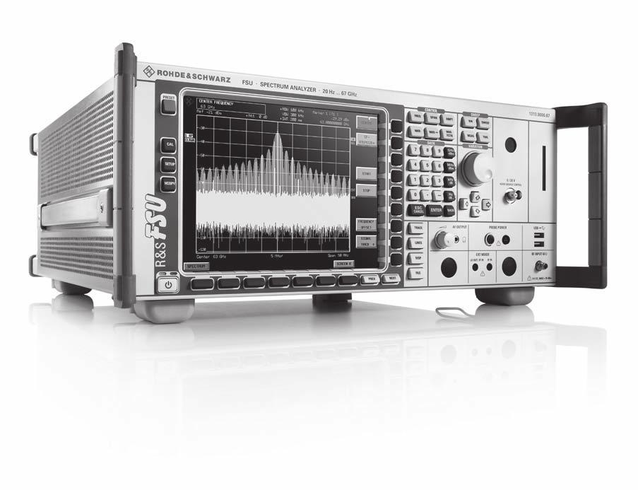
1 R&S FSU Spectrum Analyzer Specifications Test & Measurement Data Sheet 15.00
2 CONTENTS Frequency... 3 Sweep... 4 Resolution bandwidths... 4 Level... 5 I/Q data... 9 Audio demodulation... 9 Trigger functions Inputs and outputs (front panel) Inputs and outputs (rear panel) General specifications R&S FSU-B9 tracking generator, R&S FSU-B12 attenuator for tracking generator (not available for R&S FSU67)...13 R&S FSU-B21 LO/IF ports for external mixers (for R&S FSU26/43/46/50/67 only)...15 R&S FSU-B23 RF preamplifier (for R&S FSU26 only, requires R&S FSU-B25 option)...16 R&S FSU-B24 preamplifier (for R&S FSU26/43/46/50 only)...17 R&S FSU-B25 electronic attenuator and low-noise preamplifier, R&S FSU-B85 extended specifications for low-noise preamplifier 19 R&S FSU-B27 broadband FM demodulator output...20 Ordering information Options Recommended extras Rohde & Schwarz R&S FSU Spectrum Analyzer
3 Specifications Specifications apply under the following conditions: 30 minutes warm-up time at ambient temperature, specified environmental conditions met, calibration cycle adhered to, and all internal automatic adjustments performed. Data without tolerances: typical values only. Data designated "nominal" applies to design parameters and is not tested. Frequency Frequency range Frequency resolution R&S FSU3: DC coupled 20 Hz to 3.6 GHz AC coupled 1 MHz to 3.6 GHz R&S FSU8: DC coupled 20 Hz to 8 GHz AC coupled 1 MHz to 8 GHz R&S FSU26: DC coupled 20 Hz to 26.5 GHz AC coupled 10 MHz to 26.5 GHz R&S FSU43: DC coupled 20 Hz to 43 GHz R&S FSU46: DC coupled 20 Hz to 46 GHz R&S FSU50: DC coupled 20 Hz to 50 GHz R&S FSU67: DC coupled 20 Hz to 67 GHz 0.01 Hz Reference frequency, internal, nominal standard OCXO Aging per day after 30 days of continuous operation Aging per year after 30 days of continuous operation Temperature drift +5 C to +45 C Total error per year Reference frequency, internal, nominal R&S FSU-B4 option Aging per day after 30 days of continuous operation Aging per year after 30 days of continuous operation Temperature drift +5 C to +45 C Total error per year External reference frequency 1 MHz to 20 MHz, 1 Hz steps Frequency display Marker resolution Uncertainty with marker or frequency counter 1 Hz ±(marker frequency reference uncertainty + 10 % resolution bandwidth + ½ (span/(sweep points 1)) + 1 Hz) span/624 Marker tuning frequency stepsize default marker stepsize = sweep points span/(sweep points 1) Frequency counter resolution selectable 0.1 Hz to 10 khz Count accuracy S/N > 25 db ±(frequency reference error + ½ (last digit)) Display range for frequency axis 0 Hz, 10 Hz to max. frequency Resolution 0.1 Hz Max. span deviation 1 % Spectral purity, SSB phase noise (1 Hz) f = 640 MHz Residual FM RBW 10 khz, RMS < 1 Hz, nominal Carrier offset 10 Hz < 73 dbc, nominal 10 Hz with R&S FSU-B4 option fitted < 86 dbc, nominal 100 Hz < 98 dbc, typ. 104 dbc 1 khz < 116 dbc, typ. 124 dbc 10 khz < 128 dbc, typ. 133 dbc 100 khz < 128 dbc, typ. 133 dbc 1 MHz < 140 dbc, typ. 146 dbc 10 MHz typ. 160 dbc Rohde & Schwarz R&S FSU Spectrum Analyzer 3
4 SSB phase noise (dbc(1hz)) R&S FSU center frequency 200 MHz R&S FSU center frequency 1 GHz R&S FSU center frequency 5 GHz R&S FSU center frequency 25 GHz R&S FSU center frequency 50 GHz R&S FSU center frequency 65 GHz Hz 100 Hz 1 khz 10 khz 100 khz 1 MHz 10 MHz Sweep Sweep time time sweep, span = 0 Hz 1 µs to s in 5 % steps frequency sweep, span 10 Hz 2.5 ms to s in steps 10 % Max. deviation of sweep time 3 % Measurement in time domain with marker and cursor lines (resolution ns) Resolution bandwidths Sweep filters 3 db bandwidths Bandwidth uncertainty Shape factor 60 db:3 db all models except R&S FSU43 10 Hz to 20 MHz in 1/2/3/5 sequence, 50 MHz R&S FSU43 10 Hz to 10 MHz in 1/2/3/5 sequence 10 Hz to 100 khz (digital) < 3 % 200 khz to 5 MHz (analog) < 10 % 10 MHz 30 % to +10 % 20 MHz 20 % to +20 % 50 MHz, f 3.6 GHz 20 % to +20 % 50 MHz, f > 3.6 GHz 30 % to +100 % 100 khz < khz to 2 MHz < 12 3 MHz to 10 MHz < 7 20 MHz, 50 MHz < 6, nominal FFT filters 3 db bandwidths 1 Hz to 30 khz in 1/2/3/5 sequence Bandwidth uncertainty < 5 %, nominal Shape factor 60 db:3 db < 3, nominal EMI filters 6 db bandwidths 10/100/200 Hz, 1/9/10/100/120 khz, 1 MHz Bandwidth uncertainty 120 khz (digital) < 3 %, nominal 1 MHz (analog) < 10 %, nominal Shape factor 60 db:3 db 120 khz < 6, nominal 1 MHz < 12, nominal 4 Rohde & Schwarz R&S FSU Spectrum Analyzer
5 Channel filters Bandwidths Shape factor 60 db:3 db Bandwidth uncertainty Video bandwidths Level Display range 100/200/300/500 Hz 1/1.5/2/2.4/2.7/3/3.4/4/4.5/5/6/8.5/9/10/ 12.5/14/15/16/18 (RRC)/20/21/ 24.3 (RRC)/25/30/50/100/150/192/200/ 300/500 khz 1/1.2288/1.28 (RRC)/1.5/2/3/3.84 (RRC)/ (RRC)/5 MHz < 2, nominal < 2 %, nominal 1 Hz to 10 MHz in 1/2/3/5 sequence displayed noise floor to +30 dbm Maximum input level DC voltage RF input AC coupled 50 V RF input DC coupled 0 V CW RF power RF attenuation 0 db 20 dbm (= 0.1 W) RF attenuation 10 db 30 dbm (= 1 W) Pulse spectral density 97 db µv/mhz Max. pulse voltage RF attenuation 10 db 150 V Max. pulse energy RF attenuation 10 db, 10 µs 1 mws Intermodulation 1 db compression of input mixer Third-order intercept point (TOI) 0 db RF attenuation 3.6 GHz +13 dbm, nominal > 3.6 GHz R&S FSU8 +10 dbm, nominal R&S FSU26/43/46/50/67 +7 dbm, nominal level 2 10 dbm, f > 5 RBW or 10 khz, whichever is larger R&S FSU3 10 MHz f in < 300 MHz > 17 dbm, typ. 20 dbm 300 MHz f in 3.6 GHz > 19 dbm, typ. 25 dbm R&S FSU8 10 MHz f in < 300 MHz > 17 dbm, typ. 20 dbm 300 MHz f in 3.6 GHz > 20 dbm, typ. 25 dbm 3.6 GHz f in 8 GHz > 18 dbm, typ. 23 dbm R&S FSU26/43/46/50/67 10 MHz f in < 300 MHz > 17 dbm, typ. 20 dbm 300 MHz f in < 3.6 GHz > 22 dbm, typ. 27 dbm 3.6 GHz f in < 26.5 GHz > 12 dbm, typ. 15 dbm R&S FSU43/ GHz f in 40 GHz > 12 dbm, typ. 15 dbm f in > 40 GHz > 12 dbm, nominal R&S FSU GHz f in < 28 GHz > 8 dbm, typ. 11 dbm 28 GHz f in 40 GHz > 12 dbm, typ. 15 dbm f in > 40 GHz > 12 dbm, nominal R&S FSU GHz f in < 28 GHz > 8 dbm, typ. 11 dbm 28 GHz f in 40 GHz > 12 dbm, typ. 15 dbm 40 GHz < f in 50 GHz > 12 dbm, nominal f in > 50 GHz > 9 dbm, nominal Rohde & Schwarz R&S FSU Spectrum Analyzer 5
6 Second harmonic intercept (SHI) f in < 100 MHz > 35 dbm 100 MHz < f in 400 MHz > 45 dbm, typ. 55 dbm 400 MHz < f in 500 MHz > 52 dbm, typ. 60 dbm 500 MHz < f in 1 GHz > 45 dbm, typ. 55 dbm 1 GHz < f in 1.8 GHz > 35 dbm R&S FSU8/26/43/46/50 f in > 1.8 GHz > 80 dbm, nominal R&S FSU GHz < f in 4.0 GHz > 65 dbm, nominal f in > 4.0 GHz > 75 dbm, nominal Displayed average noise level 0 db RF attenuation, termination 50 Ω, log. scaling, normalized to 1 Hz RBW f < 10 khz: 10 Hz FFT filter, trace average, sweep count = 20 f 10 khz: RBW = 1 khz, VBW = 3 khz, zero span, sweep time 50 ms, sample detector, trace average, sweep count = 20, mean marker 20 Hz < 90 dbm 100 Hz < 110 dbm 1 khz < 120 dbm 10 khz < 130 dbm 100 khz < 130 dbm 1 MHz < 140 dbm 10 MHz < 153 dbm R&S FSU3 20 MHz f < 2.0 GHz < 155 dbm, typ. 158 dbm 2.0 GHz f 3.0 GHz < 153 dbm, typ. 157 dbm 3.0 GHz f 3.6 GHz < 152 dbm, typ. 156 dbm R&S FSU8 20 MHz f < 2.0 GHz < 155 dbm, typ. 158 dbm 2.0 GHz f < 3.0 GHz < 153 dbm, typ. 155 dbm 3.0 GHz f < 7 GHz < 152 dbm, typ. 154 dbm 7 GHz f 8 GHz < 150 dbm, typ. 152 dbm R&S FSU26 20 MHz f < 2 GHz < 152 dbm, typ. 156 dbm 2 GHz f < 3.6 GHz < 150 dbm, typ. 153 dbm 3.6 GHz f < 8 GHz < 152 dbm, typ. 156 dbm 8 GHz f < 13 GHz < 150 dbm, typ. 153 dbm 13 GHz f < 18 GHz < 148 dbm, typ. 151 dbm 18 GHz f < 22 GHz < 147 dbm, typ. 150 dbm 22 GHz f 26.5 GHz < 145 dbm, typ. 148 dbm R&S FSU43 20 MHz f < 2 GHz < 152 dbm, typ. 156 dbm 2 GHz f < 13 GHz < 150 dbm, typ. 153 dbm 13 GHz f < 18 GHz < 148 dbm, typ. 151 dbm 18 GHz f < 22 GHz < 147 dbm, typ. 150 dbm 22 GHz f < 26.5 GHz < 145 dbm, typ. 148 dbm 26.5 GHz f < 40 GHz < 138 dbm, typ. 141 dbm 40 GHz f 43 GHz < 133 dbm, typ. 138 dbm 6 Rohde & Schwarz R&S FSU Spectrum Analyzer
7 R&S FSU46 20 MHz f < 2 GHz < 152 dbm, typ. 156 dbm 2 GHz f < 13 GHz < 150 dbm, typ. 153 dbm 13 GHz f < 18 GHz < 148 dbm, typ. 151 dbm 18 GHz f < 22 GHz < 147 dbm, typ. 150 dbm 22 GHz f < 26.5 GHz < 145 dbm, typ. 148 dbm 26.5 GHz f < 40 GHz < 138 dbm, typ. 141 dbm 40 GHz f 46 GHz < 133 dbm, typ. 138 dbm R&S FSU50 20 MHz f < 2 GHz < 152 dbm, typ. 156 dbm 2 GHz f < 13 GHz < 150 dbm, typ. 153 dbm 13 GHz f < 18 GHz < 148 dbm, typ. 151 dbm 18 GHz f < 22 GHz < 147 dbm, typ. 150 dbm 22 GHz f < 26.5 GHz < 145 dbm, typ. 148 dbm 26.5 GHz f < 32 GHz < 138 dbm, typ. 141 dbm 32 GHz f < 46 GHz < 133 dbm, typ. 136 dbm 46 GHz f 50 GHz < 128 dbm, typ. 131 dbm R&S FSU67 20 MHz f < 2 GHz < 148 dbm, typ. 152 dbm 2 GHz f < 13 GHz < 144 dbm, typ. 148 dbm 13 GHz f < 18 GHz < 142 dbm, typ. 145 dbm 18 GHz f < 22 GHz < 140 dbm, typ. 144 dbm 22 GHz f < 26.5 GHz < 138 dbm, typ. 142 dbm 26.5 GHz f < 40 GHz < 136 dbm, typ. 140 dbm 40 GHz f < 46 GHz < 132 dbm, typ. 136 dbm 46 GHz f < 51 GHz < 128 dbm, typ. 132 dbm 51 GHz f < 57 GHz < 130 dbm, typ. 136 dbm 57 GHz f < 65 GHz < 126 dbm, typ. 130 dbm 65 GHz f 67 GHz < 120 dbm, typ. 124 dbm improvement with noise correction ON max. 13 db, nominal Immunity to interference Image frequency Intermediate frequency Spurious response Other interfering signals f 3.6 GHz > 90 db suppression, typ. > 110 db 3.6 GHz < f 40 GHz > 70 db suppression, typ. > 100 db 40 GHz < f 50 GHz > 70 db suppression, nominal f > 50 GHz > 47 db suppression f = receive frequency f 3.6 GHz > 90 db suppression, typ. > 110 db 3.6 GHz < f 4.2 GHz typ. 70 db suppression 4.2 GHz < f 50 GHz > 70 db suppression, typ. > 90 db f > 50 GHz > 47 db suppression, typ. > 50 db f = receive frequency f > 1 MHz, without input signal, < 103 dbm 0 db RF attenuation f > 100 khz mixer level < 10 dbm, f in 2.3 GHz < 80 dbc mixer level < 35 dbm, < 70 dbc 2.3 GHz < f in < 4 GHz mixer level < 10 dbm 4 GHz f < 8 GHz < 70 dbc 8 GHz f < 16 GHz < 64 dbc 16 GHz f < 26 GHz < 58 dbc 26.5 GHz f < 40 GHz < 52 dbc 40 GHz f < 50 GHz < 52 dbc, nominal 50 GHz f < 64 GHz < 47 dbc, nominal 64 GHz f 67 GHz < 43 dbc, nominal f = receive frequency Rohde & Schwarz R&S FSU Spectrum Analyzer 7
8 Level display Screen ( ) pixel (one diagram), max. 2 diagrams with independent settings Logarithmic level axis 1 db to 200 db, in steps of 1/2/5 Linear level axis 10 % of reference level per level division, 10 divisions or logarithmic scaling Number of traces one measurement diagram 3 Trace detector two measurement diagrams 6 Max Peak, Min Peak, Auto Peak (Normal), sample, RMS, average, EMI detectors Quasi Peak, CISPR-RMS, CISPR-AV Number of measurement points default value 625 range 155 to in steps of about a factor of 2 Trace functions Clear/Write, Max Hold, Min Hold, Average Trace update rate local measurement, display update rate, 80 per second 625 points, zero span remote measurement, display OFF zero span/sweep time 1 ms 70 per second span = 10 MHz, sweep time 2.5 ms 50 per second Setting range of reference level logarithmic level display 130 dbm to (+5 dbm + RF attenuation), max. 30 dbm, in steps of 0.1 db linear level display 7.0 nv to 7.07 V in steps of 1 % Units of level axis logarithmic level display dbm, dbµv, dbmv, dbµa, dbpw linear level display µv, mv, µa, ma, pw, nw Level measurement uncertainty Absolute level uncertainty at 128 MHz Frequency response referenced to 128 MHz Attenuator switching uncertainty Uncertainty of reference level setting RBW = 10 khz, level 30 dbm, < 0.2 db (σ = 0.07 db) reference level 30 dbm, RF attenuation 10 db DC coupling, RF attenuation 10 db, +20 C to +30 C 20 Hz f < 10 MHz < 0.5 db (σ = 0.17 db) 10 MHz f < 3.6 GHz < 0.3 db (σ = 0.1 db) 3.6 GHz f < 8 GHz, span < 1 GHz < 1.5 db (σ = 0.5 db) 8 GHz f < 22 GHz, span < 1 GHz < 2 db (σ = 0.7 db) 22 GHz f < 40 GHz, span < 1 GHz < 2.5 db (σ = 0.8 db) 40 GHz f < 50 GHz, span < 1 GHz < 3 db (σ = 1.0 db) 50 GHz f 67 GHz, span < 1 GHz < 4 db (σ = 1.3 db) RF attenuation > 40 db or add 0.5 db to above values f 3.6 GHz, span 1 GHz DC coupling, RF attenuation 10 db, +5 C to +45 C 20 Hz f < 3.6 GHz < 0.6 db (σ = 0.2 db) 3.6 GHz f < 26.5 GHz add 0.5 db to above values 26.5 GHz f < 50 GHz add 1.0 db to above values f 50 GHz add 1.5 db to above values RF attenuation > 40 db or add 0.5 db to above values f 3.6 GHz, span 1 GHz f = 128 MHz < 0.2 db (σ = 0.07 db) 0 db to 70 db, referenced to 10 db attenuation RF attenuation 10 db, referenced to < 0.15 db (σ = 0.05 db) 10 dbm reference level setting 8 Rohde & Schwarz R&S FSU Spectrum Analyzer
9 Display nonlinearity Logarithmic level display Linear level display Bandwidth switching error +20 C to +30 C, mixer level 10 dbm RBW 100 khz or channel filters, S/N > 20 db 0 db to 70 db < 0.1 db (σ = 0.03 db) 70 db to 90 db < 0.3 db (σ =0.1 db) 200 khz RBW 10 MHz, S/N > 16 db 0 db to 50 db < 0.2 db (σ =0.07 db) 50 db to 70 db < 0.5 db (σ =0.17 db) RBW > 10 MHz, S/N > 16 db 0 db to 50 db < 0.5 db (σ =0.17 db) 5 % of reference level referenced to RBW = 10 khz 1 Hz to 100 khz < 0.1 db (σ =0.03 db) 200 khz to 3 MHz < 0.2 db (σ =0.07 db) 5 MHz to 50 MHz < 0.5 db (σ =0.15 db) FFT filter 1 Hz to 3 khz < 0.2 db (σ =0.07 db) Total measurement uncertainty signal level 0 db to 70 db below reference level, S/N > 20 db, 10 db RF attenuation 40 db, span/rbw < 100, 95 % confidence level, +20 C to +30 C, mixer level 10 dbm 20 Hz f < 10 MHz, RBW 100 khz 0.4 db 20 Hz f < 10 MHz, RBW > 100 khz 0.5 db 10 MHz f < 3.6 GHz, RBW 100 khz 0.3 db 10 MHz f < 3.6 GHz, RBW > 100 khz 0.5 db 3.6 GHz f < 8 GHz 1.2 db 8 GHz f < 22 GHz 1.5 db 22 GHz f < 40 GHz 1.8 db 40 GHz f < 50 GHz 2.2 db 50 GHz f < 67 GHz 2.8 db I/Q data Interface GPIB or LAN interface Memory length max. 512 ksample I and Q Sample length 24 bit, each I and Q Sample rate settable in steps of khz to 32 MHz (32 MHz 2 n, n = 0 to 11) Max. signal bandwidth sample rate 2 MHz 0.8 sample rate 4 MHz 2.8 MHz 8 MHz 4.8 MHz 16 MHz 7 MHz 32 MHz 9 MHz IF pre-filter bandwidth 300 khz to 10 MHz, 1/2/3/5 steps Audio demodulation AF demodulation types Audio output Marker stop time in spectrum mode AM and FM loudspeaker and phone jack 100 ms to 60 s Rohde & Schwarz R&S FSU Spectrum Analyzer 9
10 Trigger functions Trigger Trigger source Trigger offset Max. deviation of trigger offset Gated sweep Gate source Gate delay Gate length Max. deviation of gate length span 10 Hz span = 0 Hz free run, video, external, IF level (mixer level 10 dbm to 50 dbm) 125 ns to 100 s, resolution min. 125 ns (or 1 % of offset) ±(125 ns to 100 s), resolution min. 125 ns, dependent on sweep time ±(31.25 ns + (0.1 % trigger offset)) external, IF level, video 1 µs to 100 s 125 ns to 100 s, resolution min. 125 ns or 1 % of gate length ±(31.25 ns + (0.05 % gate length)) Inputs and outputs (front panel) RF input Impedance Connector VSWR Setting range of attenuator 50 Ω R&S FSU3, R&S FSU8 N female R&S FSU26 test port adapter APC 3.5 mm/n female R&S FSU43, R&S FSU46 test port adapter 2.92 mm (K)/N female R&S FSU50 test port adapter 2.4 mm/n female R&S FSU mm/v female RF attenuation 10 db, DC coupled f < 3.6 GHz < 1.5 R&S FSU8 3.6 GHz f < 8 GHz < 2 R&S FSU26/43/46/50/ GHz f < 18 GHz < GHz f < 26.5 GHz < GHz f < 40 GHz < GHz f < 50 GHz < 3, nominal 50 GHz f 67 GHz < 3.5, nominal RF attenuation < 10 db or AC coupled typ db to 75 db, in 5 db steps Probe power supply Supply voltages +15 V DC, 12.6 V DC and ground, max. 150 ma, nominal Power supply for antennas etc 5-pin connector Supply voltages ±10 V and ground, max. 100 ma, nominal Power supply for noise source BNC female Output voltage 0 V and 28 V, switchable, nominal USB interface type A plug, version 2.0 AF output Connector Output impedance Open-circuit voltage 3.5 mm mini jack 10 Ω up to 1.5 V, adjustable 10 Rohde & Schwarz R&S FSU Spectrum Analyzer
11 Inputs and outputs (rear panel) IF 20.4 MHz Impedance Bandwidth Level BNC female 50 Ω RBW 30 khz 1.67 resolution bandwidth, min. 2.6 khz RBW = 50 khz, 100 khz 400 khz 200 khz RBW 10 MHz equal to resolution bandwidth RBW 100 khz, FFT filter, 20 dbm at reference level mixer level > 70 dbm RBW = 200 khz to 10 MHz, 0 dbm at reference level mixer level > 50 dbm IF MHz not available with R&S FSU43, BNC female active only if RBW > 10 MHz Impedance 50 Ω Bandwidth RBW > 10 MHz equal to resolution bandwidth Level mixer level 0 dbm typ. 10 db below mixer level Video output Impedance Output voltage Reference output Impedance Output frequency Level Reference input Impedance Input frequency range Required level RBW 200 khz, logarithmic scaling, full scale internal reference external reference BNC female 50 Ω 0 V to 1 V (EMF) BNC female 50 Ω 10 MHz same as reference input signal > 0 dbm, nominal BNC female 50 Ω 1 MHz f in 20 MHz, in 1 Hz steps > 0 dbm from 50 Ω Sweep output Output voltage BNC female 0 V to 5 V, proportional to displayed frequency External trigger/gate input Trigger voltage Input impedance BNC female 0.5 V to 3.5 V 10 kω IEC/IEEE bus control interface to IEC (IEEE 488.2) Command set SCPI or HP8566 compatible Connector 24-pin Amphenol female Interface functions SH1, AH1, T6, L4, SR1, RL1, PP1, DC1, DT1, C0 LAN interface USB interface Serial interface Printer interface Mouse interface Connector for external monitor (VGA) 10/100 BaseT, RJ45 upper connector type A plug, version 1.1 lower connector type A plug, version 2.0 RS-232-C (COM), 9-pin female connectors parallel (Centronics compatible) PS/2 compatible 15-pin D-Sub Rohde & Schwarz R&S FSU Spectrum Analyzer 11
12 General specifications Display 21 cm LC TFT color display (8.4") Resolution ( ) pixel (SVGA resolution) Pixel failure rate < Mass memory Mass memory hard disk, USB flash disk (not supplied) Data storage >500 instrument settings and traces Mass memory R&S FSU-B20 option hard disk replaced by a flash disk Temperature Ranges Climatic loading operating temperature range +5 C to +40 C permissible temperature range +0 C to +50 C storage temperature range 40 C to +70 C R&S FSU-B20 option operating temperature range 0 C to +50 C permissible temperature range 0 C to +55 C +40 C at 95 % relative humidity, in line with EN Mechanical resistance Vibration Shock Recommended calibration interval RFI suppression sinusoidal random R&S FSU-B20 option: random vibration operation with external reference operation with internal reference 5 Hz to 150 Hz, max. 2 g at 55 Hz; 0.5 g from 55 Hz to 150 Hz; in line with EN Hz to 100 Hz, acceleration 1 g (RMS) 40 g shock spectrum, in line with MIL-STD-810E Method Procedure I and MIL-PRF-28800F 10 Hz to 300 Hz, acceleration 1.9 g (RMS) 2 years 1 year in line with EMC Directive 2004/108/EC including: IEC/EN , IEC/EN , CISPR 11/EN 55011, IEC/EN , IEC/EN Power supply AC supply 100 V to 240 V, 3.1 A to 1.3 A; 50 Hz to 400 Hz, class of protection I in line with VDE 411 typ. 130 VA typ. 150 VA Power consumption R&S FSU3, R&S FSU8 R&S FSU26/43/46/50/67 Safety in line with EN , IEC , UL , CAN/CSA-C22.2 No Test mark VDE, GS, CSA, CSA-NRTL Dimensions W H D 435 mm 192 mm 460 mm (17.13 in 7.56 in in) Weight, without options, nominal R&S FSU kg (32.2 lb) R&S FSU kg (33.95 lb) R&S FSU kg (36.4 lb) R&S FSU43/46/ kg (37.0 lb) R&S FSU kg (38.3 lb) 12 Rohde & Schwarz R&S FSU Spectrum Analyzer
13 R&S FSU-B9 tracking generator, R&S FSU-B12 attenuator for tracking generator (not available for R&S FSU67) Unless specified otherwise, specifications not valid for frequency range from 3 RBW to +3 RBW, however at least not valid from 100 khz to +100 khz. Maximum output level +5 dbm (peak modulation in the case of amplitude-modulated signals). Frequency Frequency range Resolution Frequency offset Setting range Resolution 100 khz to 3.6 GHz 1 Hz ±200 MHz 1 Hz Spectral purity SSB phase noise f = 500 MHz, carrier offset 10 khz normal mode with frequency offset with FM modulation ON typ. 120 dbc (1 Hz) typ. 110 dbc (1 Hz) typ. 110 dbc (1 Hz) Level Level setting range with option R&S FSU-B12 30 dbm to +5 dbm in steps of 0.1 db 100 dbm to +5 dbm in steps of 0.1 db Max. deviation of output level Absolute Frequency response f = 128 MHz, < 1 db (σ = 0.34 db) output level 20 dbm to 0 dbm referenced to level at 128 MHz, sweep time > 100 ms, +5 C to +45 C output level 20 dbm to 0 dbm, < 3 db, typ. 1.9 db 100 khz to 3.6 GHz output level 30 dbm to 20 dbm, 3 db f = 100 khz to 3.6 GHz additional deviation with < 1 db R&S FSU-B12, 100 khz to 3.6 GHz Dynamic range Attenuation measurement range RBW = 1 khz, f > 10 MHz 100 db Harmonics output level 10 dbm typ. 30 dbc Spurious, nonharmonics output level 0 dbm typ. 30 dbc Level sweep Level range Max. deviation of output level f = 100 khz to 2 GHz output level 0 dbm to 5 dbm output level 5 dbm to 15 dbm output level 15 to 25 dbm f = 2 GHz to 3 GHz output level 0 dbm to 25 dbm 0 dbm to 25 dbm < 1.5 db < 2 db < 3 db < 3 db Rohde & Schwarz R&S FSU Spectrum Analyzer 13
14 Modulation Modulation format external I/Q, AM, FM Input voltage full scale AM, FM, V pp 1 V I/Q U i U q = 0.5 V AM f Center > f Mod, span = 0 Hz Modulation depth 0 % to 99 % Modulation frequency response 0 Hz to 5 MHz 1 db 0 Hz to 30 MHz 3 db FM f Center > f Mod, span = 0 Hz Frequency deviation full range 100 Hz, 1 khz, 10 khz, 100 khz, 1 MHz Modulation frequency range deviation 10 MHz 0 Hz to 1 khz deviation 1 MHz 0 Hz to 100 khz Modulation frequency response 0 Hz to 100 khz 1 db I/Q modulation f Center > f Mod, span = 0 Hz Modulation frequency response 0 Hz to 5 MHz 1 db 0 Hz to 30 MHz 3 db Modulation deviation of tracking I/Q modulation, typical values, baseband signals generated by the R&S AMIQ generator EVM NADC/TETRA/PDC RMS 2 % peak 4 % PHS RMS 2 % peak 5 % Phase error GSM/DCS1800/PCS1900 RMS 1.5 peak 5 Rho factor IS-95 CDMA Inputs and outputs (front panel) RF output VSWR N female, 50 Ω 100 khz f 2 GHz GHz f 3.6 GHz 1.5 Inputs and outputs (rear panel) TG I/AM IN BNC female Impedance 50 Ω Input voltage V pp 1 V TG Q/FM IN BNC female Impedance 50 Ω Input voltage V pp 1 V 14 Rohde & Schwarz R&S FSU Spectrum Analyzer
15 R&S FSU-B21 LO/IF ports for external mixers (for R&S FSU26/43/46/50/67 only) LO signal Frequency range Level 7.0 GHz to 15.5 GHz +20 C to +30 C dbm ± 1 db +5 C to +40 C dbm ± 3 db IF input IF frequency Full scale level Level uncertainty MHz 2-port mixer 20 dbm (LO output/if input, front panel) 3-port mixer (IF input, front panel) 20 dbm IF input level 30 dbm, RBW 30 khz, two-port mixer, LO output/if input (front panel) +20 C to +30 C < 1 db +5 C to +40 C < 3 db three-port mixer, IF input (front panel) +20 C to +30 C < 1 db +5 C to +40 C < 3 db Inputs and outputs (front panel) LO output/if input IF input SMA female, 50 Ω SMA female, 50 Ω Rohde & Schwarz R&S FSU Spectrum Analyzer 15
16 R&S FSU-B23 RF preamplifier (for R&S FSU26 only, requires R&S FSU-B25 option) Level measurement uncertainty Frequency response preamplifier ON 3.6 GHz to 8 GHz < 2.0 db (σ = 0.7 db) 8 GHz to 22 GHz < 2.5 db (σ = 0.8 db) 22 GHz to 26.5 GHz < 3.0 db (σ = 1 db) Displayed average noise level 0 db RF attenuation, termination 50 Ω, RBW = 1 khz, VBW = 3 khz, zero span, sweep time 50 ms, sample detector, log. scaling, trace average, sweep count = 20, mean marker, normalized to 1 Hz RBW preamplifier OFF 3.6 GHz to 8 GHz R&S FSU26 specifications + 2 db 8 GHz to 26.5 GHz R&S FSU26 specifications + 3 db preamplifier ON 3.6 GHz to 8 GHz < 162 dbm, typ. 165 dbm 8 GHz to 13 GHz < 159 dbm, typ. 162 dbm 13 GHz to 18 GHz < 157 dbm, typ. 160 dbm 18 GHz to 22 GHz < 154 dbm, typ. 159 dbm 22 GHz to 26.5 GHz < 150 dbm, typ. 155 dbm improvement with noise correction ON max. 13 db, nominal 16 Rohde & Schwarz R&S FSU Spectrum Analyzer
17 R&S FSU-B24 preamplifier (for R&S FSU26/43/46/50 only) Frequency range R&S FSU khz to 26.6 GHz R&S FSU khz to 43 GHz R&S FSU khz to 46 GHz R&S FSU khz to 50 GHz Nominal gain 30 db Displayed average noise level (DANL) RF attenuation = 0 db, termination = 50 Ω, log. scaling, normalized to 1 Hz RBW, preamplifier OFF f < 10 khz: RBW = 10 Hz FFT filter, trace average, sweep count = 20, f 10 khz: RBW = 1 khz, VBW = 3 khz, span = 0 Hz, sweep time = 50 ms, trace average, sample detector, sweep count = 20, mean marker 20 Hz < 90 dbm 100 Hz < 110 dbm 1 khz < 120 dbm 10 khz < 130 dbm 100 khz < 130 dbm 1 MHz < 140 dbm 10 MHz < 151 dbm 20 MHz f < 2 GHz < 151 dbm, typ. 154 dbm 2 GHz f < 8 GHz < 149 dbm, typ. 152 dbm 8 GHz f < 13 GHz < 147 dbm, typ. 150 dbm 13 GHz f < 18 GHz < 145 dbm, typ. 148 dbm 18 GHz f < 22 GHz < 144 dbm, typ. 147 dbm 22 GHz f < 26.5 GHz < 140 dbm, typ. 143 dbm 26.5 GHz f < 32 GHz < 135 dbm, typ. 138 dbm 32 GHz f < 42 GHz < 130 dbm, typ. 133 dbm 42 GHz f 50 GHz < 125 dbm, typ. 128 dbm RF attenuation = 0 db, termination = 50 Ω, log. scaling, normalized to 1 Hz RBW, preamplifier ON RBW = 1 khz, VBW = 3 khz, span = 0 Hz, sweep time = 50 ms, trace average, sample detector, sweep count = 20, mean marker 100 khz < 140 dbm 1 MHz < 150 dbm 10 MHz < 163 dbm 20 MHz f < 2 GHz < 164 dbm, typ. 167 dbm 2 GHz f < 3.6 GHz < 163 dbm, typ. 166 dbm 3.6 GHz f < 20 GHz < 165 dbm, typ. 168 dbm 20 GHz f < 33 GHz < 163 dbm, typ. 166 dbm 33 GHz f < 42 GHz < 158 dbm, typ. 161 dbm 42 GHz f 50 GHz < 152 dbm, typ. 155 dbm improvement with noise correction ON max. 13 db, nominal Rohde & Schwarz R&S FSU Spectrum Analyzer 17
18 Level measurement uncertainty Absolute level uncertainty at 128 MHz Frequency response referenced to 128 MHz RBW = 10 khz, level 30 dbm, reference level 30 dbm, RF attenuation 10 db preamplifier OFF < 0.2 db (σ = 0.07 db) preamplifier ON < 0.3 db (σ = 0.1 db) DC coupling, RF attenuation 10 db, preamplifier OFF, +20 C to +30 C 20 Hz f < 10 MHz < 0.5 db (σ = 0.16 db) 10 MHz f < 3.6 GHz < 0.3 db (σ = 0.1 db) 3.6 GHz f < 8 GHz < 1.5 db (σ = 0.5 db) 8 GHz f < 22 GHz, span < 1 GHz < 2.0 db (σ = 0.7 db) 22 GHz f < 40 GHz, span < 1 GHz < 2.5 db (σ = 0.8 db) 40 GHz f 50 GHz, span < 1 GHz < 3.0 db (σ = 1 db) RF attenuation > 40 db or add 0.5 db to above values f 3.6 GHz, span 1 GHz DC coupling, RF attenuation 10 db, preamplifier OFF, +5 C to +45 C 20 Hz f < 3.6 GHz < 0.6 db (σ = 0.2 db) 3.6 GHz f < 26.5 GHz add 0.5 db to above values 26.5 GHz f 50 GHz add 1.0 db to above values RF attenuation > 40 db or add 0.5 db to above values f 3.6 GHz, span 1 GHz DC coupling, RF attenuation 10 db, preamplifier ON, +20 C to +30 C 100 khz f < 10 MHz < 0.8 db (σ = 0.27 db) 10 MHz f < 3.6 GHz < 0.6 db (σ = 0.2 db) 3.6 GHz f < 8 GHz < 2.0 db (σ = 0.7 db) 8 GHz f < 22 GHz, span < 1 GHz < 2.5 db (σ = 0.8 db) 22 GHz f < 40 GHz, span < 1 GHz < 3.0 db (σ = 1 db) 40 GHz f 50 GHz, span < 1 GHz < 3.5 db (σ = 1.2 db) RF attenuation > 40 db or add 0.5 db to above values f 3.6 GHz, span 1 GHz DC coupling, RF attenuation 10 db, preamplifier ON, +5 C to +45 C 100 khz f < 10 MHz < 1.0 db (σ = 0.3 db) 10 MHz f < 3.6 GHz < 0.8 db (σ = 0.27 db) 3.6 GHz f < 26.5 GHz add 0.5 db to above values 26.5 GHz f 50 GHz add 1.0 db to above values RF attenuation > 40 db or add 0.5 db to above values f 3.6 GHz, span 1 GHz Intermodulation Second harmonic intercept (SHI) f in > 1.8 GHz > 65 dbm, nominal 18 Rohde & Schwarz R&S FSU Spectrum Analyzer
19 R&S FSU-B25 electronic attenuator and low-noise preamplifier, R&S FSU-B85 extended specifications for low-noise preamplifier Frequency Frequency range R&S FSU3/26/43/46/50 electronic attenuator preamplifier R&S FSU8 electronic attenuator preamplifier 10 MHz to 3.6 GHz 100 khz to 3.6 GHz 10 MHz to 8 GHz 100 khz to 8 GHz Setting range Electronic attenuator Preamplifier Level measurement uncertainty Frequency response Reference error 0 db to 30 db, in 5 db steps 20 db, switchable with preamplifier or electronic attenuator 10 MHz to 50 MHz < 1 db (σ = 0.34 db) 50 MHz to 3.6 GHz < 0.6 db (σ = 0.2 db) 3.6 GHz to 8 GHz < 2.0 db (σ = 0.7 db) at 128 MHz, RBW 100 khz, reference level 30 dbm, RF attenuation 10 db electronic attenuator < 0.3 db (σ = 0.1 db) preamplifier < 0.3 db (σ = 0.1 db) Displayed average noise level Displayed average noise level with R&S FSU-B85, extended specification for low-noise preamplifier 0 db RF attenuation, termination 50 Ω, RBW = 1 khz, VBW = 3 khz, zero span, sweep time 50 ms, sample detector, log. scaling, trace average, sweep count = 20, mean marker, normalized to 1 Hz RBW preamplifier ON R&S FSU3/8/26 10 MHz to 2.0 GHz < 162 dbm 2.0 GHz to 3.6 GHz < 160 dbm R&S FSU8 3.6 GHz to 8 GHz < 157 dbm R&S FSU43/46/50 10 MHz to 40 MHz < 160 dbm 40 MHz to 2 GHz < 162 dbm 2 GHz to 3.6 GHz < 160 dbm with the R&S FSU-B25 built in, the average noise level values displayed by the base units degrade by (R&S FSU-B25 OFF) 20 Hz to 3.6 GHz 1 db R&S FSU8 3.6 GHz to 8 GHz 2 db preamplifier OFF, electronic attenuator 0 db 20 Hz to 3.6 GHz typ. 2.5 db R&S FSU8 3.6 GHz to 8 GHz typ. 3.5 db improvement with noise correction ON max. 13 db, nominal 0 db RF attenuation, termination 50 Ω, RBW = 1 khz, VBW = 3 khz, zero span, sweep time 50 ms, sample detector, log. scaling, trace average, sweep count = 20, mean marker, normalized to 1 Hz RBW preamplifier ON R&S FSU3, R&S FSU8 10 MHz to 100 MHz < 164 dbm, typ. 166 dbm 100 MHz to 200 MHz < 168 dbm, typ. 170 dbm 200 MHz to 2 GHz < 166 dbm, typ. 168 dbm 2 GHz to 3.6 GHz < 165 dbm, typ. 167 dbm R&S FSU8 3.6 GHz to 6 GHz < 165 dbm, typ. 167 dbm 6 GHz to 8 GHz < 163 dbm, typ. 165 dbm improvement with noise correction ON max. 11 db, nominal Rohde & Schwarz R&S FSU Spectrum Analyzer 19
20 Intermodulation Third-order intercept point (TOI) electronic attenuator ON, Δf > 5 RBW or 10 khz 10 MHz to 300 MHz > 17 dbm 300 MHz to 3.6 GHz > 20 dbm 3.6 GHz to 8 GHz > 18 dbm R&S FSU-B27 broadband FM demodulator output Frequency deviation Frequency deviation 5 MHz Deviation + modulation frequency 5 MHz FM slope load impedance 50 Ω 280 mv/mhz ± 20 % Frequency response DC to 1 MHz (< 1 MHz deviation) < 0.4 db 4 MHz (< 1MHz deviation) typ. 3 db Distortion 1 MHz deviation + > 30 dbc 1 MHz modulation frequency Residual FM LF-lowpass 100 khz < 100 Hz RMS Lowpass filters 3 db bandwidth 30 khz, 100 khz, 300 khz, 1 MHz 20 Rohde & Schwarz R&S FSU Spectrum Analyzer
21 Ordering information Designation Type Order No. Spectrum Analyzer, 20 Hz to 3.6 GHz R&S FSU Spectrum Analyzer, 20 Hz to 8 GHz R&S FSU Spectrum Analyzer, 20 Hz to 26.5 GHz R&S FSU Spectrum Analyzer, 20 Hz to 43 GHz R&S FSU Spectrum Analyzer, 20 Hz to 46 GHz R&S FSU Spectrum Analyzer, 20 Hz to 50 GHz R&S FSU Spectrum Analyzer, 20 Hz to 67 GHz R&S FSU Accessories supplied Power cable, printed quick start guide and CD-ROM (with operating manual and service manual). R&S FSU26: test port adapter with 3.5 mm female ( ) and N female ( ) connector. R&S FSU43, R&S FSU46: test port adapter with 2.92 mm (K) female ( ) and N female ( ) connector. R&S FSU50: test port adapter with 2.4 mm female ( ) and N female ( ) connector. Rohde & Schwarz R&S FSU Spectrum Analyzer 21
22 Options Designation Type Order No. Retrofittable Remarks Options OCXO, low aging/improved phase noise at 10 Hz R&S FSU-B yes carrier offset Tracking Generator, 100 khz to 3.6 GHz R&S FSU-B yes not available for R&S FSU67 External Generator Control R&S FSP-B yes Output Attenuator, 0 db to 70 db, for R&S FSU-B9 R&S FSU-B yes requires R&S FSU-B9, not available for R&S FSU67 Removable Hard Disk R&S FSU-B no excludes R&S FSU-B20 Second Hard Disk for R&S FSU-B18 R&S FSU-B requires R&S FSU-B18 Extended Environmental Specifications R&S FSU-B no LO/IF Ports for External Mixers R&S FSU-B yes only for R&S FSU26/43/46/50/67 20 db Preamplifier, 3.6 GHz to 26.5 GHz R&S FSU-B no only for R&S FSU26, requires R&S FSU-B25 30 db Preamplifier, 100 khz to 50 GHz R&S FSU-B yes only for R&S FSU26/43/46/50. excludes R&S FSU-B23, R&S FSU-B25 Electronic Attenuator, 0 db to 30 db, and 20 db Preamplifier (3.6 GHz) R&S FSU-B yes not available for R&S FSU67 Broadband FM Demodulator Output, R&S FSU-B yes max. dev. 5 MHz Vector Signal Analyzer R&S FSU-B no not available for R&S FSU67 Extended Specifications for Low-Noise Preamplifier of R&S FSU-B25 option Firmware/Software GSM/EDGE Application Firmware R&S FS-K FM Measurement Demodulator R&S FS-K Bluetooth 1 Application Firmware R&S FS-K Power Sensor Measurements R&S FS-K Application Firmware for Noise Figure and Gain Measurements R&S FSU-B no only for R&S FSU3 and R&S FSU8, requires R&S FSU-B25 R&S FS-K preamplifier (e.g. R&S FSU-B25) recommended Application Firmware for Phase Noise Measurement R&S FS-K GPP BTS/Node B FDD Application Firmware R&S FS-K GPP UE FDD Application Firmware (incl HSUPA) R&S FS-K GPP HSDPA BTS Application Firmware R&S FS-K requires R&S FS-K72 3GPP TD-SCDMA BTS Application Firmware R&S FS-K GPP TD-SCDMA UE Application Firmware R&S FS-K CDMA /IS-95 (cdmaone)/1xev-dv BTS R&S FS-K Application Firmware CDMA2000 1xEV-DV MS Application Firmware R&S FS-K CDMA2000 1xEV-DO BTS Application Firmware R&S FS-K (incl Rev A) CDMA2000 1xEV-DO MS Application Firmware R&S FS-K The Bluetooth word mark and logos are owned by the Bluetooth SIG, Inc. and any use of such marks by Rohde & Schwarz is under license. 2 CDMA2000 is a registered trademark of the Telecommunications Industry Association (TIA-USA). 22 Rohde & Schwarz R&S FSU Spectrum Analyzer
23 Recommended extras Designation Type Order No. Headphones IEC/IEEE Bus Cable, length 1 m R&S PCK IEC/IEEE Bus Cable, length 2 m R&S PCK " Rack Adapter R&S ZZA Adapter for mounting on telescopic rails R&S ZZA-T (only with 19" Adapter R&S ZZA-411) Matching pads, 50 Ω/75 Ω L Section, matching at both ends R&S RAM Series Resistor, 25 Ω, matching at one R&S RAZ end (taken into account in instrument function RF INPUT 75 Ω) SWR bridges, 50 Ω SWR Bridge, 5 MHz to 3 GHz R&S ZRB X SWR Bridge, 40 khz to 4 GHz R&S ZRC X High power attenuators 100 W, 3/6/10/20/30 db, 1 GHz R&S RBU XX (XX = 03/06/10/20/30) 50 W, 3/6/10/20/30 db, 2 GHz R&S RBU XX (XX = 03/06/10/20/30) 50 W, 20 db, 6 GHz R&S RDL Connectors and cables N-type adapter for R&S RT-Zx probes R&S RT-ZA Probe power connector, 3 pin DC blocks DC Block, 10 khz to 18 GHz (type N) R&S FSE-Z External harmonic mixers (for R&S FSU26/43/46/50 with R&S FSU-B21 option) Harmonic Mixer 40 GHz to 60 GHz R&S FS-Z Harmonic Mixer 50 GHz to 75 GHz R&S FS-Z Harmonic Mixer 60 GHz to 90 GHz R&S FS-Z Harmonic Mixer 75 GHz to 110 GHz R&S FS-Z For R&S FSU26 only Test port adapter N male Test port adapter 3.5 mm male Microwave Measurement Cable with test R&S FSE-Z port adapter set N male and 3.5 mm male For R&S FSU43 and R&S FSU46 only Test port adapter N male Test port adapter K male Test port adapter 2.4 mm female R&S FSE-Z For R&S FSU50 only Test port adapter N male Test port adapter K female Test port adapter K male Rohde & Schwarz R&S FSU Spectrum Analyzer 23
24 Service you can rely on J Worldwide J Local and personalized J Customized and flexible J Uncompromising quality J Long-term dependability About Rohde & Schwarz Rohde & Schwarz is an independent group of companies specializing in electronics. It is a leading supplier of solutions in the fields of test and measurement, broadcasting, radiomonitoring and radiolocation, as well as secure communications. Established more than 75 years ago, Rohde & Schwarz has a global presence and a dedicated service network in over 70 countries. Company headquarters are in Munich, Germany. Environmental commitment JJEnergy-efficient products JJContinuous improvement in environmental sustainability JJISO certified environmental management system Certified Quality System ISO 9001 Rohde & Schwarz GmbH & Co. KG Regional contact JJ Europe, Africa, Middle East customersupport@rohde-schwarz.com JJ North America TEST RSA ( ) customer.support@rsa.rohde-schwarz.com JJ Latin America customersupport.la@rohde-schwarz.com JJ Asia/Pacific customersupport.asia@rohde-schwarz.com R&S is a registered trademark of Rohde & Schwarz GmbH & Co. KG Trade names are trademarks of the owners Printed in Germany (as) PD Version June 2011 R&S FSU Subject to change Rohde & Schwarz GmbH & Co. KG München, Germany
ESU EMI Test Receiver Specifications
 ESU EMI Test Receiver Specifications Test & Measurement Data Sheet 02.01 CONTE NT S BASE UNIT... 3 FREQUENCY... 3 RECEIVER SCAN... 4 SWEEP... 4 PRESELECTION... 4 IF AND RESOLUTION BANDWIDTHS... 5 LEVEL...
R&S FSMR Measuring Receiver Specifications
 Test & Measurement Data Sheet 09.00 R&S FSMR Measuring Receiver Specifications CONTENTS Specifications... 3 Frequency...3 Measuring receiver... 3 Frequency counter...3 RF power...4 RF level (tuned receiver)...5
R&S FSQ Signal Analyzer Specifications
 Established 1981 Advanced Test Equipment Rentals www.atecorp.com 800-404-ATEC (2832) R&S FSQ Signal Analyzer Specifications Test & Measurement Data Sheet 11.00 CONTENTS Specifications... 3 Frequency...3
R&S FPC1000 Spectrum Analyzer Specifications
 R&S FPC1000 Spectrum Analyzer Specifications year Data Sheet Version 01.00 CONTENTS Definitions... 3 Specifications... 4 Frequency... 4 Sweep time... 4 Bandwidth... 4 Level... 5 Trigger functions... 6
R&S FSV Signal and Spectrum Analyzer Specifications
 Test & Measurement Data Sheet 05.00 R&S FSV Signal and Spectrum Analyzer Specifications CONTENTS Specifications... 3 Frequency...3 Sweep time...4 Resolution bandwidths...5 Level...6 Measurement speed...12
R&S FSW Signal and Spectrum Analyzer Specifications
 Established 1981 Advanced Test Equipment Rentals www.atecorp.com 800-404-ATEC (2832) R&S FSW Signal and Spectrum Analyzer Specifications Test & Measurement Data Sheet 05.01 CONTENTS Definitions... 3 Specifications...
R&S FPS Signal and Spectrum Analyzer Specifications
 E stablished 1981 Advanced Test Equipment Rentals www.atecorp.com 800-404-ATEC (2832) FPS_dat_sw_en_3606-9433-22_cover.indd 1 Data Sheet 02.01 Test & Measurement R&S FPS Signal and Spectrum Analyzer Specifications
R&S FPS Signal and Spectrum Analyzer Specifications
 R&S FPS Signal and Spectrum Analyzer Specifications Data Sheet Version 06.00 CONTENTS Definitions... 3 Specifications... 4 Frequency... 4 Sweep time... 5 Resolution bandwidths... 6 Level... 7 Trigger functions...
R&S FS-Z60/75/90/110 Harmonic Mixers for the R&S FSP/FSU/ FSQ/FSUP/FSV
 Test & Measurement Data Sheet 04.00 R&S FS-Z60/75/90/110 Harmonic Mixers for the R&S FSP/FSU/ FSQ/FSUP/FSV R&S FS-Z60/75/ 90/110 Harmonic Mixers At a glance The R&S FS-Z60/-Z75/-Z90/-Z110 harmonic mixers
R&S FPL1000 Spectrum Analyzer Specifications
 R&S FPL1000 Spectrum Analyzer Specifications year Data Sheet Version 02.00 CONTENTS Definitions... 3 Specifications... 4 Frequency... 4 Sweep time... 5 Resolution bandwidths... 5 Level... 6 Measurement
Spectrum Analyzer 1.6 GHz 3 GHz R&S HMS-X
 HMS-X_bro_de-en_3607-0181-3X_v0200.indd 1 Product Brochure 02.00 Test & Measurement Spectrum Analyzer 1.6 GHz 3 GHz R&S HMS-X 15.03.2016 15:24:06 1 Basic Unit + 3 Options Key facts Frequency range: 100
R&S ZN-Z154 Calibration Unit Specifications
 ZN-Z154_dat-sw_en_3607-0481-22_v0101_cover.indd 1 Data Sheet 01.01 Test & Measurement R&S ZN-Z154 Calibration Unit Specifications 25.06.2014 10:27:09 CONTENTS Definitions... 3 Measurement range... 4 Effective
R&S FSV-K40 Phase Noise Measurement Application Specifications
 FSV-K40_dat-sw_en_5213-9705-22_cover.indd 1 Data Sheet 02.00 Test & Measurement R&S FSV-K40 Phase Noise Measurement Application Specifications 06.10.2014 14:51:49 CONTENTS Specifications... 3 Ordering
R&S ZV-Z81 Multiport Test Set, models.05/.09/.29 Specifications
 ZV-Z81_models5_9_29_dat-sw_en_5213-6864-22_Cover.indd 1 Data Sheet 04.01 Test & Measurement R&S ZV-Z81 Multiport Test Set, models.05/.09/.29 Specifications 17.04.2013 12:47:27 CONTENTS Definitions... 3
R&S ZNL Vector Network Analyzer Specifications
 R&S ZNL Vector Network Analyzer Specifications year Data Sheet Version 01.00 CONTENTS Definitions... 3 Specifications... 4 Measurement range... 4 Measurement speed... 5 Measurement accuracy... 6 Effective
R&S FSW-B512R Real-Time Spectrum Analyzer 512 MHz Specifications
 R&S FSW-B512R Real-Time Spectrum Analyzer 512 MHz Specifications Data Sheet Version 02.00 CONTENTS Definitions... 3 Specifications... 4 Level... 5 Result display... 6 Trigger... 7 Ordering information...
R&S ZVA110 Vector Network Analyzer Specifications
 ZVA110_dat-sw_en_5214-4813-22_cover.indd 1 Data Sheet 04.00 Test & Measurement R&S ZVA110 Vector Network Analyzer Specifications 15.11.2013 14:42:28 CONTENTS Definitions... 3 Specifications... 4 Overview...
R&S ZN-Z85 Switch Matrix Specifications
 R&S ZN-Z85 Switch Matrix Specifications Data Sheet Version 01.02 CONTENTS Definitions... 3 Block diagrams... 4 Specifications... 5 General features... 5 Performance data... 5 Remote control... 5 Switching
R&S FSW-K160RE 160 MHz Real-Time Measurement Application Specifications
 FSW-K160RE_dat-sw_en_3607-1759-22_v0200_cover.indd 1 Data Sheet 02.00 Test & Measurement R&S FSW-K160RE 160 MHz Real-Time Measurement Application Specifications 06.04.2016 17:16:27 CONTENTS Definitions...
R&S SMBV-Z1 Reference Frequency Converter Specifications
 Test & Measurement Data Sheet 01.01 R&S SMBV-Z1 Reference Frequency Converter Specifications Version 01.01, July 2011 CONTENTS Definitions... 3 Introduction... 4 Specifications... 4 Input signal...4 Output
R&S ZN-Z103 Calibration Unit Specifications. Data Sheet V02.01
 R&S ZN-Z103 Calibration Unit Specifications Data Sheet V02.01 CONTENTS Definitions... 3 Measurement range... 5 Effective system data... 5 General data... 6 Ordering information... 7 2 Rohde & Schwarz R&S
R&S RT-Zxx High-Bandwidth Probes Specifications
 R&S RT-Zxx High-Bandwidth Probes Specifications Test & Measurement Data Sheet 14.00 CONTENTS Definitions... 3 Probe/oscilloscope chart... 4 R&S RT-ZZ80 transmission line probe... 5 R&S RT-ZS10/-ZS10E/-ZS20/-ZS30
LSA Series. Signal Analyzer. Any signal, Any time, Any place
 Analyzer High-end www.nex1.co.kr LSA Series Signal Analyzer LSA-30/LSA-132/LSA-265 Any signal, Any time, Any place range: 3Hz to 3GHz, 13.2GHz, and 26.5GHz Open architecture based on Window XP and PXI
R&S FSV Signal and Spectrum Analyzer Specifications
 FSV_FL_dat-sw_en_3606-7982-22_Cover_cc.indd 1 Data Sheet 10.01 Test & Measurement R&S FSV Signal and Spectrum Analyzer Specifications 27.02.2015 09:52:34 CONTENTS Specifications... 3 Frequency... 3 Sweep
R&S EDS300 DME/Pulse Analyzer Specifications
 R&S EDS300 DME/Pulse Analyzer Specifications year Data Sheet Version 04.01 CONTENTS Definitions... 3 Specifications... 4 Frequency... 4 Level... 4 DME signal analysis... 4 TACAN signal analysis (R&S EDS-K1
EX-IQ-Box Digital Signal Interface Module Specifications
 Test & Measurement Data Sheet 01.01 EX-IQ-Box Digital Signal Interface Module Specifications Introduction The R&S EX-IQ-Box is a digital interface module that provides flexible digital baseband inputs
R&S FSV Signal and Spectrum Analyzer Specifications
 R&S FSV Signal and Spectrum Analyzer Specifications Data Sheet Version 12.01 CONTENTS Specifications... 3 Frequency... 3 Sweep time... 4 Resolution bandwidths... 5 Level... 6 Trigger functions... 12 I/Q
R&S FSV-K73 3G FDD UE (UL) Measurements incl. HSUPA Specifications
 Measurements incl. HSUPA Specifications") FSV-K73_dat-sw_en_5214-0976-22_cover.indd 1 Data Sheet 02.00 Test & Measurement R&S FSV-K73 3G FDD UE (UL) Measurements incl. HSUPA Specifications 01.08.2013 17:36:27 CONTENTS Specifications... 3 Frequency...
FSV-K73_dat-sw_en_5214-0976-22_cover.indd 1 Data Sheet 02.00 Test & Measurement R&S FSV-K73 3G FDD UE (UL) Measurements incl. HSUPA Specifications 01.08.2013 17:36:27 CONTENTS Specifications... 3 Frequency...
R&S ETH Handheld TV Analyzer Portable DVB-T/H signal analysis up to 3.6/8 GHz
 R&S ETH Handheld TV Analyzer Portable DVB-T/H signal analysis up to 3.6/8 GHz Broadcast Product Brochure 02.00 R&S ETH Handheld TV Analyzer At a glance The R&S ETH handheld TV analyzer was specially designed
R&S ZVA-Zxx Millimeter-Wave Converters Specifications
 ZVA-Zxx_dat-sw_en_5214.2033.22_umschlag.indd 1 Data Sheet 13.00 Test & Measurement R&S ZVA-Zxx Millimeter-Wave Converters Specifications 28.01.2013 15:08:06 CONTENTS General information... 3 Definitions...
Bluetooth Tester CBT. Specifications. Specifications. Version January 2006
 Specifications Version 03.00 Bluetooth Tester CBT January 2006 Specifications CONTENTS UNIT SPECIFICATIONS...3 TIMEBASE TCXO...3 REFERENCE FREQUENCY INPUT...3 RF GENERATOR...3 RF ANALYZER...5 Power meter
Spectrum Analyzer 1.6 GHz 3 GHz HMS-X
 Spectrum Analyzer 1.6 GHz 3 GHz 1 Basic Unit + 3 Options Your Spectrum Analyzer Key facts Frequency range: 100 khz to 1.6 GHz/3 GHz* 1 Spectral purity greater than -100 dbc/hz (at 100 khz) SWEEP from 20
R&S FSV-K8 Bluetooth /EDR Measurement Application Specifications
 R&S FSV-K8 Bluetooth /EDR Measurement Application Specifications Test & Measurement Data Sheet 01.01 CONTENTS R&S FSV-K8 Bluetooth /EDR measurement application... 3 Frequency...3 Measurement parameters...3
R&S FSVA Signal and Spectrum Analyzer Specifications
 FSVA_dat-sw_en_3607-2790-22_v0100_cover.indd 1 Data Sheet 01.00 Test & Measurement R&S FSVA Signal and Spectrum Analyzer Specifications 25.04.2016 16:43:42 CONTENTS Definitions... 3 Specifications... 4
R&S SMF100A Microwave Signal Generator Specifications
 R&S SMF100A Microwave Signal Generator Specifications Test & Measurement Data Sheet 04.00 Specifications Specifications apply under the following conditions: 30 minutes warm-up time at ambient temperature,
R&S ZN-Z151/-Z152/-Z153 Calibration Unit Specifications
 ZN-Z151_152_153_dat-sw_en_3607-0881-22_v0100_cover.indd 1 Data Sheet 01.00 Test & Measurement R&S ZN-Z151/-Z152/-Z153 Calibration Unit Specifications 07.10.2014 11:35:47 CONTENTS Definitions... 3 Measurement
Model 7330 Signal Source Analyzer Dedicated Phase Noise Test System V1.02
 Model 7330 Signal Source Analyzer Dedicated Phase Noise Test System V1.02 A fully integrated high-performance cross-correlation signal source analyzer from 5 MHz to 33+ GHz Key Features Complete broadband
R&S ZND Vector Network Analyzer Specifications
 R&S ZND Vector Network Analyzer Specifications year Test & Measurement Data Sheet 02.01 CONTENTS Definitions... 3 Measurement range... 4 Measurement speed... 5 Measurement accuracy... 7 Effective system
R&S ADMC8 Multicoupler Active UHF multicoupler for 8-port ATC signal distribution
 Secure Communications Product Brochure 01.00 R&S ADMC8 Multicoupler Active UHF multicoupler for 8-port ATC signal distribution R&S ADMC8 Multicoupler At a glance The R&S ADMC8 is a multicoupler specifically
R3267/3273 Spectrum Analyzers
 R3267/3273 Spectrum Analyzers For 3rd-Generation Mobile Communications Present Digital Communication standards (W-CDMA, PDC, PHS, IS-136, GSM, DECT, cdmaone ) R3267/3273 New communication technologies
RS Pro SPECTRUM ANALYZER SSA3000X SERIES
 Product Datasheet ENGLISH Stock No: 1236443 (RSSA3021X) 1236444 (RSSA3032X) RS Pro SPECTRUM ANALYZER SSA3000X SERIES Features and Benefits RSSA3032X XX RSSA3021X All-Digital IFTechnology Frequency Range
R&S HF907DC SHF Downconverter Specifications
 Radiomonitoring & Radiolocation Data Sheet 01.03 R&S HF907DC SHF Downconverter Specifications CONTENTS Definitions... 3 Specifications... 4 Frequency conversion... 4 Input and output properties... 4 Rechargeable
R&S SGS100A SGMA RF Source Specifications
 R&S SGS100A SGMA RF Source Specifications Test & Measurement Data Sheet 04.00 CONTENTS Key features... 3 Definitions... 4 RF performance... 5 Frequency... 5 Reference frequency... 5 Level... 6 Spectral
R&S RT-Zxx High-Voltage and Current Probes Specifications
 R&S RT-Zxx High-Voltage and Current Probes Specifications Test & Measurement Data Sheet 14.00 CONTENTS Definitions... 3 Probe/oscilloscope chart... 4 R&S RT-ZH10/-ZH11 high-voltage probes... 5 R&S RT-ZD01
R&S SGU100A SGMA Upconverter Specifications
 R&S SGU100A SGMA Upconverter Specifications Test & Measurement Data Sheet 03.00 CONTENTS Key features... 3 Definitions... 4 Specifications... 5 RF performance... 5 Frequency... 5 Level... 5 Spectral purity...
7000 Series Signal Source Analyzer & Dedicated Phase Noise Test System
 7000 Series Signal Source Analyzer & Dedicated Phase Noise Test System A fully integrated high-performance cross-correlation signal source analyzer with platforms from 5MHz to 7GHz, 26GHz, and 40GHz Key
R&S FSW-K54 EMI Measurement Application Detecting and eliminating electromagnetic
 R&S FSW-K54 EMI Measurement Application Detecting and eliminating electromagnetic interference Test & Measurement Product Brochure 01.00 R&S FSW-K54 EMI Measurement Application At a glance The R&S FSW-K54
R&S FSW-K76/-K77 3GPP TD-SCDMA BS/UE Measurement Applications Specifications
 R&S FSW-K76/-K77 3GPP TD-SCDMA BS/UE Measurement Applications Specifications Test & Measurement Data Sheet 01.00 CONTENTS Definitions... 3 Specifications... 4 Frequency... 4 Level... 4 Signal acquisition...
R&S ZNBT Vector Network Analyzer Specifications
 R&S ZNBT Vector Network Analyzer Specifications year Data Sheet Version 05.02 CONTENTS Definitions... 3 Measurement range... 4 Measurement speed... 6 Measurement accuracy of the R&S ZNBT8... 8 Measurement
R&S RSC Step Attenuator Where precise signal levels count
 Test & Measurement Product Brochure 01.00 Step Attenuator Where precise signal levels count Step Attenuator At a glance The is a switchable, mechanical step attenuator. It is available in various models
R&S Cable Rider ZPH Cable and Antenna Analyzer Specifications
 R&S Cable Rider ZPH Cable and Antenna Analyzer Specifications year Data Sheet Version 01.01 CONTENTS Definitions... 3 Specifications of the R&S Cable Rider ZPH Cable and Antenna Analyzer... 4 Frequency...
R&S GU221 Filter Control Unit Specifications
 R&S GU221 Filter Control Unit Specifications Secure Communications Data Sheet 01.00 Definitions General Product data applies under the following conditions: Three hours storage at ambient temperature followed
R&S FSV-K76 TD-SCDMA BS (DL) Measurements Specifications
 Measurements Specifications") FSV_K76_dat-sw_en_5214-1572-22_cover.indd 1 Data Sheet 02.00 Test & Measurement R&S FSV-K76 TD-SCDMA BS (DL) Measurements Specifications 07.08.2013 18:42:49 CONTENTS Specifications... 3 Frequency... 3
FSV_K76_dat-sw_en_5214-1572-22_cover.indd 1 Data Sheet 02.00 Test & Measurement R&S FSV-K76 TD-SCDMA BS (DL) Measurements Specifications 07.08.2013 18:42:49 CONTENTS Specifications... 3 Frequency... 3
HP 71910A and 71910P Wide Bandwidth Receiver Technical Specifications
 HP 71910A and 71910P Wide Bandwidth Receiver Technical Specifications 100 Hz to 26.5 GHz The HP 71910A/P is a receiver for monitoring signals from 100 Hz to 26.5 GHz. It provides a cost effective combination
R&S ZVA-Zxx Millimeter-Wave Converters Specifications
 R&S ZVA-Zxx Millimeter-Wave Converters Specifications Data Sheet Version 19.00 CONTENTS Definitions... 3 General information... 4 Specifications... 5 Test port... 5 Source input (RF IN)... 5 Local oscillator
R&S DDF200M Digital Direction Finder Specifications
 R&S DDF200M Digital Direction Finder Specifications Data Sheet Version 02.00 CONTENTS Definitions... 3 Specifications... 4 Frequency... 4 Direction finding... 4 Linearity... 4 Interference rejection...
R&S HA-Z24E External Preamplifier 1 GHz to 85 GHz Specifications
 R&S HA-Z24E External Preamplifier 1 GHz to 85 GHz Specifications Data Sheet Version 01.01 Definitions General Product data applies under the following conditions: Three hours storage at ambient temperature
SMS3000X Series Spectrum Analyzer
 Data Sheet SMS3000X Series Spectrum Analyzer SMS3032X SMS3021X General Description SMS3000X series spectrum analyzer has a frequency range from 9 khz up to 2.1 GHz/3.2 GHz, it is light weight and small
Test and Communications Antennas for the R&S TS8991 OTA Performance Test System Specifications
 Test and Communications Antennas for the R&S TS8991 OTA Performance Test System Specifications R&S TC-TA18 cross-polarized Vivaldi test antenna, R&S TC-CA6 linear-polarized communications antenna Data
Agilent 8560 E-Series Spectrum Analyzers
 Agilent 8560 E-Series Spectrum Analyzers Data Sheet 8560E 30 Hz to 2.9 GHz 8561E 30 Hz to 6.5 GHz 8562E 30 Hz to 13.2 GHz 8563E 30 Hz to 26.5 GHz 8564E 30 Hz to 40 GHz 8565E 30 Hz to 50 GHz 8565E SPECTRUM
R&S FSQ-K91/K91n/K91ac WLAN a/b/g/j/n/ac Application Firmware Specifications
 R&S FSQ-K91/K91n/K91ac WLAN 802.11a/b/g/j/n/ac Application Firmware Specifications Test & Measurement Data Sheet 03.00 CONTENTS OFDM analysis (IEEE 802.11a, IEEE 802.11g OFDM, IEEE 802.11j, )... 3 Frequency...3
R&S FSMR Measuring Receiver All-in-one calibration of signal generators and attenuators
 R&S FSMR Measuring Receiver All-in-one calibration of signal generators and attenuators Product Brochure Version 04.00 year FSMR_Bro_en_0758-2319-12_v0400.indd 1 19.05.2017 14:41:56 R&S FSMR Measuring
R&S Cable Rider ZPH Cable and Antenna Analyzer Specifications
 R&S Cable Rider ZPH Cable and Antenna Analyzer Specifications year Data Sheet Version 02.02 CONTENTS Definitions... 3 Specifications... 4 Frequency... 4 Measurements... 4 Channel power meter (R&S ZPH-K19
Test and Communications Antennas for the R&S TS8991 OTA Performance Test System Specifications
 Test and Communications Antennas for the R&S TS8991 OTA Performance Test System Specifications R&S TC-TA18 cross-polarized Vivaldi test antenna, R&S TC-TA85CP cross-polarized Vivaldi test antenna, R&S
Product Brochure Version R&S ENV A Four-Line V-Network RFI voltage measurements at high currents
 Product Brochure Version 01.00 200 A Four-Line V-Network RFI voltage measurements at high currents ENV4200_bro_en_5214-8390-12_v0100.indd 1 26.01.2017 15:22:54 200 A Four-Line V-Network At a glance The
R&S TS-ISC In-System Calibration Kit On-site calibration solution for R&S CompactTSVP
 TS-ISC_bro_en_5214-1972-12.indd 1 Product Brochure 02.00 Test & Measurement R&S TS-ISC In-System Calibration Kit On-site calibration solution for R&S CompactTSVP 24.09.2013 10:08:56 R&S TS-ISC In-System
Agilent PSA Series Spectrum Analyzers Data Sheet
 Agilent PSA Series Spectrum Analyzers Data Sheet E4443A E4445A E4440A E4446A E4448A 3 Hz to 6.7 GHz 3 Hz to 13.2 GHz 3 Hz to 26.5 GHz 3 Hz to 44 GHz 3 Hz to 50 GHz The Agilent PSA series offers high-performance
SSA3000X Series Spectrum Analyzer
 SSA3000X Series Spectrum Analyzer SSA3000X Spectrum Analyzer Data Sheet Features and Benefits SSA3032X SSA3021X All-Digital IF Technology Frequency Range from 9 khz up to 3.2 GHz -161 dbm/hz Displayed
Product Brochure Version R&S TSML-CW Radio Network Analyzer Powerful scanner for CW applications
 Product Brochure Version 02.01 Radio Network Analyzer Powerful scanner for CW applications TSML-CW_bro_en_5214-3246-12_v0200.indd 1 22.08.2017 11:50:23 Radio Network Analyzer At a glance The is the ideal
R&S TS-BCAST DVB-H IP Packet Inserter Compact DVB H signal generator with integrated IP packet inserter
 Test & Measurement Product Brochure 02.00 R&S TS-BCAST DVB-H IP Packet Inserter Compact DVB H signal generator with integrated IP packet inserter R&S TS-BCAST DVB-H IP packet Inserter At a glance The R&S
Product Brochure Version HZ-15_16_17_bro_en_ _v0100.indd 1
 Product Brochure Version 1. R&S HZ-15/R&S HZ-17 Probe Sets R&S HZ-16 Preamplifier E and H near-field emission measurements with test receivers, spectrum analyzers and oscilloscopes HZ-15_16_17_bro_en_5213-6687-12_v1.indd
SSA3000X Series Spectrum Analyzer
 SSA3000X Series Spectrum Analyzer SSA3000X Spectrum Analyzer Data Sheet Features and Benefits SSA3032X SSA3021X All-Digital IF Technology Frequency Range from 9 khz up to 3.2 GHz -161 dbm/hz Displayed
EUTRA/LTE Downlink Specifications
 Test & Measurement Data Sheet 03.00 EUTRA/LTE Downlink Specifications R&S FS-K100PC/-K102PC/-K104PC R&S FSV-K100/-K102/-K104 R&S FSQ-K100/-K102/-K104 R&S FSW-K100/-K102/-K104 CONTENTS Definitions... 3
Product Brochure Version R&S RSC Step Attenuator Where precise signal levels count
 Product Brochure Version 02.00 Step Attenuator Where precise signal levels count RSC_bro_en_5214-4413-12_v0200.indd 1 07.09.2018 10:36:40 Step Attenuator At a glance The is a switchable, mechanical step
R&S TS-PMB Switch Matrix Module High-density, 90-channel, full matrix relay multiplexer module
 TS-PMB_bro_en_0758-0600-12.indd 1 Product Brochure 02.00 Test & Measurement Switch Matrix Module High-density, 90-channel, full matrix relay multiplexer module Switch Matrix Module At a glance Typical
R&S DST200 RF Diagnostic Chamber Specifications
 DST200_dat-sw_en_5214-3600-22_v0500_cover.indd 1 Data Sheet 05.00 Test & Measurement R&S DST200 RF Diagnostic Chamber Specifications 08.04.2016 15:35:59 CONTENTS Definitions... 3 Base unit... 4 R&S DST200
R&S FPS-K18 Amplifier Measurements Specifications
 R&S FPS-K18 Amplifier Measurements Specifications Data Sheet Version 02.00 Specifications The specifications of the R&S FPS-K18 amplifier measurements are based on the data sheet of the R&S FPS signal
R&S EDST300 TACAN/DME Station Tester Specifications
 R&S EDST300 TACAN/DME Station Tester Specifications year Data Sheet Version 01.01 CONTENTS Definitions... 3 Specifications... 4 Standards... 4 Frequency... 4 TX Power Measurement (R&S EDST300 analyzer)...
R&S RT-Zxx Standard Probes Specifications
 R&S RT-Zxx Standard Probes Specifications Test & Measurement Data Sheet 16.00 CONTENTS Definitions... 3 Probe/oscilloscope chart... 4 R&S RT-ZP03 passive probe... 5 R&S RT-ZP05(S) passive probe... 8 R&S
R&S AVG050 DVB Satellite Receiver Specifications
 AVG050-SAT_dat-sw_en_3606-8508-22_v0400_cover.indd 1 Data Sheet 04.00 Broadcast and Media R&S AVG050 DVB Satellite Receiver Specifications 14.11.2014 14:40:08 CONTENTS Definitions... 3 Specifications...
R&S Spectrum Rider FPH Handheld spectrum analyzer
 R&S Spectrum Rider FPH Handheld spectrum analyzer PD 3607.2149.32 V 01.00 Small form factor to handle big tasks SpectrumRider_fly_en_3607_2149_32_v0100.indd 3 R&S Spectrum Rider FPH Modern and rugged portable
Spectrum Master. Compact Handheld Spectrum Analyzer. Technical Data Sheet
 Technical Data Sheet Spectrum Master Compact Handheld Spectrum Analyzer MS2712E MS2713E 100 khz to 4 GHz 100 khz to 6 GHz Introduction Anritsu introduces its next generation compact handheld Spectrum Analyzers
R&S M3TR R&S VT3050C 50 W VHF/UHF Compact Power Amplifier Specifications
 Secure Communications Data Sheet 01.00 R&S M3TR R&S VT3050C 50 W VHF/UHF Compact Power Amplifier Specifications CONTENTS Specifications... 3 General data...3 RF data...4 Protection...4 Mechanical data...4
R&S FSW-K144 5G NR Measurement Application Specifications
 R&S FSW-K144 5G NR Measurement Application Specifications Data Sheet Version 01.00 CONTENTS Definitions... 3 Specifications... 4 Overview... 4 Assignment of option numbers to link modes... 4 Supported
DATENBLATT. SSA3000X-Serie. HABEN SIE FRAGEN ODER WÜNSCHEN SIE EIN INDIVIDUELLES ANGEBOT? Unser Team berät Sie gerne persönlich.
 DATENBLATT SSA3000X-Serie HABEN SIE FRAGEN ODER WÜNSCHEN SIE EIN INDIVIDUELLES ANGEBOT? Unser Team berät Sie gerne persönlich. TELEFON + 49 (0) 81 41/36 97-0 TELEFAX + 49 (0) 81 41/36 97-30 E-MAIL info@plug-in.de
R&S SGMA Product Family Compact fast reliable
 Test & Measurement Product Brochure 5. R&S SGMA Product Family Compact fast reliable R&S SGS1A SGMA RF Source, R&S SGU1A SGMA Upconverter R&S SGMA Product Family At a glance The R&S SGS1A is an RF source
Spectrum Analyzers. 2399A 9 khz to 3 GHz Spectrum Analyzer.
 Spectrum Analyzers 2399A 9 khz to 3 GHz Spectrum Analyzer A spectrum analyzer with outstanding performance and a user friendly visual interface simplifying many complex measurements 9 khz to 3 GHz fully
DVG MPEG-2 Measurement Generator
 Data sheet Version 04.00 DVG MPEG-2 Measurement Generator October 2006 Digital TV test signals at a keystroke The DVG is a universal generator for digital TV signals. It generates in an endless loop a
E4416A/E4417A EPM-P Series Power Meters and E-Series E9320 Peak and Average Power Sensors DATA SHEET
 E4416A/E4417A EPM-P Series Power Meters and E-Series E9320 Peak and Average Power Sensors DATA SHEET EPM-P Power Meter Specifications Specifications describe the instrument s warranted performance and
Agilent N9344C Handheld Spectrum Analyzer (HSA)
") Agilent N9344C Handheld Spectrum Analyzer (HSA) 20 GHz Data Sheet Field testing just got easier www.agilent.com/find/hsa If you are making measurements in the field, the Agilent N9344C handheld spectrum
Agilent N9344C Handheld Spectrum Analyzer (HSA) 20 GHz Data Sheet Field testing just got easier www.agilent.com/find/hsa If you are making measurements in the field, the Agilent N9344C handheld spectrum
R&S SMB100A RF and Microwave Signal Generator Specifications
 R&S SMB100A RF and Microwave Signal Generator Specifications year Test & Measurement Data Sheet 09.00 CONTENTS Definitions... 3 Specifications... 4 Hardware and software option concept... 4 RF performance...
R&S FK2900M HF Antenna Tuning Unit For stationary and shipboard applications
 Secure Communications Product Brochure 05.00 R&S FK2900M HF Antenna Tuning Unit For stationary and shipboard applications R&S FK2900M HF Antenna Tuning Unit At a glance The R&S FK2900M is an antenna tuning
R&S NRP Power Sensor Family Specifications
 NRP-Family_dat-sw_en_3607-0852-22_Cover.indd 1 Data Sheet 01.01 Test & Measurement R&S NRP Power Sensor Family Specifications 08.12.2014 09:29:11 CONTENTS Definitions... 3 Overview of the R&S NRPxxS(N)
R&S NRPM Over-the-Air (OTA) Power Measurement Solution Specifications
 Power Measurement Solution Specifications") R&S NRPM Over-the-Air (OTA) Power Measurement Solution Specifications year Data Sheet Version 04.00 CONTENTS Definitions... 3 R&S NRPM3 three-channel sensor module... 4 R&S NRPM-A66 single-polarized antenna
R&S NRPM Over-the-Air (OTA) Power Measurement Solution Specifications year Data Sheet Version 04.00 CONTENTS Definitions... 3 R&S NRPM3 three-channel sensor module... 4 R&S NRPM-A66 single-polarized antenna
R&S FSMR Measuring Receiver All-in-one calibration of signal generators and attenuators
 R&S FSMR Measuring Receiver All-in-one calibration of signal generators and attenuators Test & Measurement Product Brochure 03.01 R&S FSMR Measuring Receiver At a glance The R&S FSMR measuring receiver
R&S TSMx Radio Network Analyzers Powerful scanner family for mobile applications
 Test & Measurement Data Sheet 01.00 R&S TSMx Radio Network Analyzers Powerful scanner family for mobile applications R&S TSMx Radio Network Analyzers At a glance The R&S TSML, R&S TSMU and R&S TSMQ form
Agilent N9343C Handheld Spectrum Analyzer (HSA)
") Agilent N9343C Handheld Spectrum Analyzer (HSA) 13.6 GHz Data Sheet Field testing just got easier www.agilent.com/find/hsa If you are making measurements in the field, the Agilent N9343C handheld spectrum
Agilent N9343C Handheld Spectrum Analyzer (HSA) 13.6 GHz Data Sheet Field testing just got easier www.agilent.com/find/hsa If you are making measurements in the field, the Agilent N9343C handheld spectrum
Agilent PSA Series Spectrum Analyzers
 Agilent PSA Series Spectrum Analyzers Data Sheet 40/80 MHz Analysis Bandwidth Now Available On 50 GHz PSA! Models E4443A 3 Hz to 6.7 GHz E4445A 3 Hz to 13.2 GHz E4440A 3 Hz to 26.5 GHz* E4447A 3 Hz to
R&S MDS-21 Absorbing Clamp Measurement of disturbance power and screening effectiveness on cables
 MDS-21_bro_en_3607-5319-12_v0101.indd 1 Product Brochure 01.01 Test & Measurement Measurement of disturbance power and screening effectiveness on cables 17.11.2016 15:21:31 At a glance The absorbing clamp
Keysight N9344C Handheld Spectrum Analyzer (HSA)
") Keysight N9344C Handheld Spectrum Analyzer (HSA) 20 GHz Data Sheet 02 Keysight N9344C Handheld Spectrum Analyzer (HSA) Data Sheet Field testing just got easier If you are making measurements in the field,
Keysight N9344C Handheld Spectrum Analyzer (HSA) 20 GHz Data Sheet 02 Keysight N9344C Handheld Spectrum Analyzer (HSA) Data Sheet Field testing just got easier If you are making measurements in the field,