006 Dual Divider. Two clock/frequency dividers with reset
|
|
|
- Chester Williamson
- 6 years ago
- Views:
Transcription


1 006 Dual Divider Two clock/frequency dividers with reset Comments, suggestions, questions and corrections are welcomed & encouraged: 1 castlerocktronics.com
2 Contents 3 0. Build Documents Photos Bill of Materials Schematic Layout Drill Template 7 1. Explanation & Analysis A quick build The 7400 series TTL vs. CMOS HC00 chips What is a divider anyway? Using it for rhythm Using it for pitch Using it to generate an average One last note 9 2. Modifications Faster reset Bigger current limiting resistors Version history: 07/April/2015 First draft 2 castlerocktronics.com


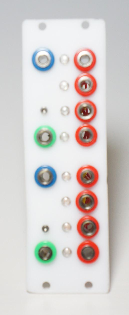
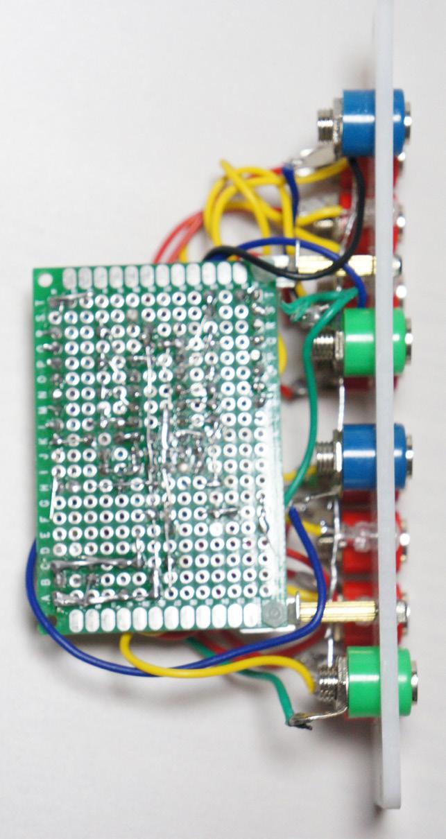

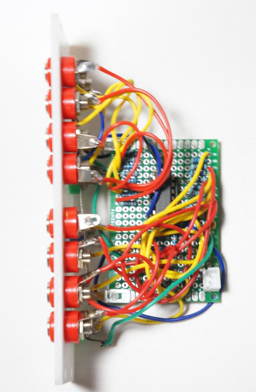
3 0. Build Documents 0.1 Photos castlerocktronics.com 3
4 0.2 Schematic 0.2 Bill of Materials ICs 78L05 74HC393 Resistors 1kΩ 4.7kΩ 10kΩ 100kΩ Capacitors 470pF 100nF 10μF 47μF x8 x8 x2 x4 x2 Diodes 1N4004 1N4148 LEDs Connectors Bannana jacks Blue Green Red XH-2.54 x8 x2 x2 x4 4 castlerocktronics.com
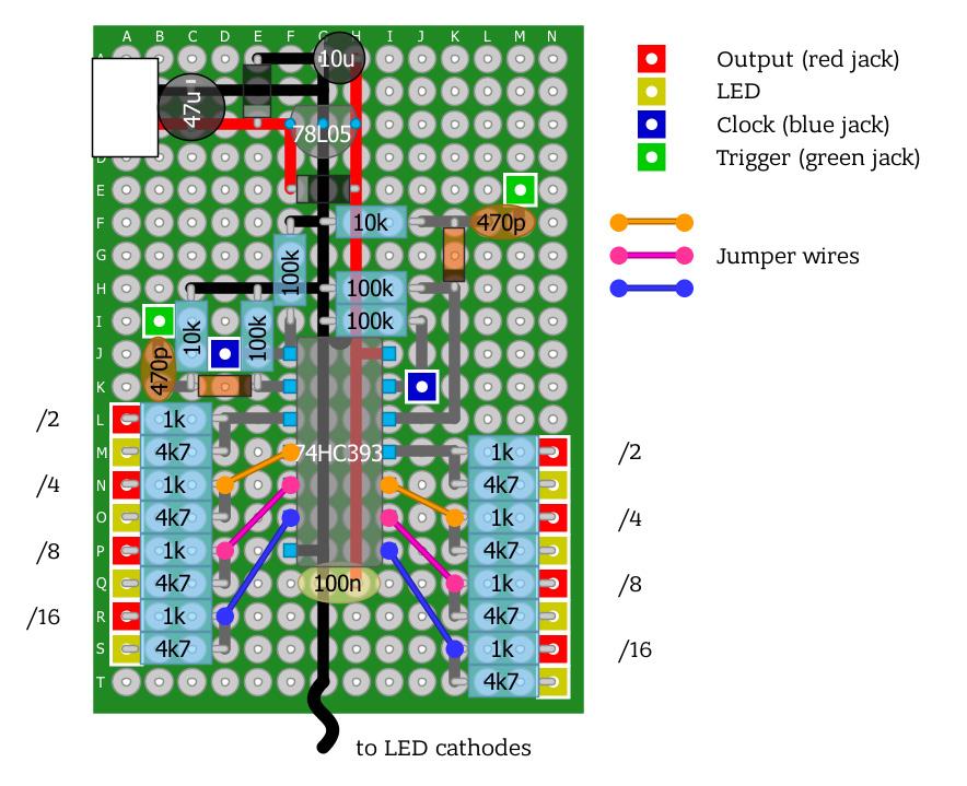
5 0.3 Layout castlerocktronics.com 5
6 0.4 Drill Template 8HP U castlerocktronics.com
7 1. Explanation & Analysis 1.1 A quick build This is another chip-to-jack module, just like #004 Dual Shift Divider. The great thing about modules like this is that they are really easy to build! Who doesn t love a module that can be done in an afternoon? Even better is that I don t have to write much in the way of an article so it s faster for me too. What is worth spending some time on though, is a little bit about different families of logic. 1.2 The 7400 series The dual divider takes advantage of the lovely 74HC393, the first (but almost certainly not the last) logic chip we are going to use that is not from the 4000 series. The 7400 series is just another collection of logic chips, though instead of CMOS most of them use TTL technology a.k.a. transistor-transistor logic. This means that instead of the Complimentary Metal-Oxide Semiconductor (CMOS) transistors used in the 4000 series, the 7400 series is based on Bipolar Junction Transistors (BJT). Without going into tons of detail about semiconductors, just know that BJTs came before MOS TTL vs. CMOS I know what you are thinking now: newer means better, right? Well, yes and no. CMOS chips do have a number of advantages over TTL chips. In fact, the 4000 series was introduced to provide alternatives to the 7400 series. Notice I used the word alternatives and not replacements. The CMOS technology used in the 4000 series has a number of desirable qualities: Higher input impedance Lower output impedance Lower power consumption Wider range of usable supply voltages Simpler circuit design (cheaper!) All of these things are obviously pretty great. Awesome even. So why did I say alternative over replacement? One reason: speed. TTL chips are still considerably faster than CMOS. CMOS usually can t handle much more than 1MHz, while TTL can blast along at speeds from 10MHz castlerocktronics.com to around 200MHz! Luckily for us, human ears only hear up to 20kHz, and that s if you have amazing hearing. This means we can get by with CMOS and take advantage of all those really nice features without having to worry about them being too slow. So why are we using a 7400 series chip in this module? Because there is no 4000 series equivalent. The 4000 series does have dividers check out the 4020, 4024 & 4040 but it does not have any that have two dividers on the same chip. I like having more than one of the same thing in a module, especially since you can chain things like shift registers and dividers together anyway. There is another problem though TTL and CMOS are not compatible. The outputs and inputs of CMOS chips behave a little too differently for us to be able to hook them up directly. There are a few solutions, though we are going for the simplest: HC00 chips You may have noticed that the bill of materials demands that you pick up the 74HC393. Stress on the HC. Well, with the advantages of CMOS proving to be so great, manufacturers started making High-speed Cmos version of the 7400 series chips, as well as special HCT chips, which are compatible with TTL logic. These chips are still slower than the best TTL chips, but they are faster than the 4000 series. So why don t the make the 4000 series chips faster? The answer is that is not what the 4000 series is about. They sacrifice speed though being more than fast enough for synth use in favour of keeping all those other nice advantages. 1.3 What is a divider anyway? Dividers, also called binary ripple counters, are just chips that take a square wave input and run it through a bunch of cascaded flip-flops to half its speed, then half it again, and again, and again (fig 1.3a - next page) Sometimes it will do this as many as 14 times, though the 74HC393 only does it four times. This can have a lot of useful applications, most of which have to do with timing and keeping things in sync even if they need to run at different 7
 speeds.")
8 square-wave sub-oscillator for cheap, though in this case they tend to use a single flip-flop rather than the cascaded flip-flops in a divider chip. One or two octaves down is often enough... nah, who am I kidding. We all want at least 4 down for speaker blowing bass action Using it to generate an average (fig 1.3a) speeds. For us, this has two particularly musical uses: rhythm and pitch Using it for rhythm In Western music, rhythm is usually divisive. The idea is that a steady pulse is divided into equal sub-divisions usually two, sometimes three, but you can use other prime numbers if you are pretentious and then those may be divided again into further smaller parts. This can be seen in the American names for note durations: the whole note, half-note, quarter-note, 8 th -note, 16 th -note, etc. However, our divider goes in the opposite direction: since it creates an output at half the speed, this would be like using a note value twice as large. Two quarter-notes fit into a half-note. As for using this in our modular, this means we can use one of our LFOs to create a steady pulse of changes that we can treat as the 16 th -notes of our tempo, and then use the divider to generate the 8 th -notes, quarter-notes, half-notes and whole-notes. This will let us clock different parts of our synth at different speeds while keeping it rhythmical. There is one last use, and also something to keep in mind about the outputs of the divider. Each successive division will get closer and closer to a perfect square-wave, averaging out irregularities in the previous division. This can be used to smooth out faster streams of random bits, but it also means that intentional irregular rhythms at the output will tend to get lost at the outputs. This also means that if the input s pulse width gets modulated this ends up getting lost in the output. Just something to keep in mind. 1.4 One last note Something that you should note about the output of the divider is revealed in (fig 1.3a). Look carefully at where the output transitions happen in relation to the input waveform. You will notice that they happen on the falling edge. This isn t a big deal for making sub-octaves, but it is a big deal if you are using it for rhythm as most inputs act on the rising edge. This can be interesting to play with, as you can use it to make your main clock sound off-beat compared to everything else. However, if you don t want this you might want to run your clock through an inverter first, and don t worry, that s the next module! Using it for pitch Similar to rhythm, our ears treat pitch in a very mathematical way. An octave up from any pitch is double the frequency, the octave below is half the frequency. Since our divider halves frequencies, this means we can use it to get some nice fat sub-octave doubling, really fattening up the sounds we can get out of our synth. This is actually the technique used in lots of commercial analog synths and modules to get a nice 8 castlerocktronics.com
9 2. Modifications 2.1 Faster reset I decided on using much smaller caps in the leading edge detector than the ones I used in module #004 Dual Shift Register. This is primarily because I knew I was going to use this module for fat bassline sounds and I wanted the option of being able to do audio rate sync on it for hyper-aggressive sync bass. BZZZZZZT. 2.2 Bigger current limiting resistors I ran into a bit of an issue with some of the other modules when I did excessive cable stacking and I managed to track it down to the fact I was using 1kΩ resistors for the LEDs, which was causing things to get loaded down and stop behaving properly. What s more, 1kΩ was a bit wasteful in the first place. I ve been wasting more current than I have to on making the LEDs excessively bright. castlerocktronics.com 9
University of Illinois at Urbana-Champaign
 University of Illinois at Urbana-Champaign Digital Electronics Laboratory Physics Department Physics 40 Laboratory Experiment 3: CMOS Digital Logic. Introduction The purpose of this lab is to continue
Laboratory 9 Digital Circuits: Flip Flops, One-Shot, Shift Register, Ripple Counter
 page 1 of 5 Digital Circuits: Flip Flops, One-Shot, Shift Register, Ripple Counter Introduction In this lab, you will learn about the behavior of the D flip-flop, by employing it in 3 classic circuits:
16 Stage Bi-Directional LED Sequencer
 16 Stage Bi-Directional LED Sequencer The bi-directional sequencer uses a 4 bit binary up/down counter (CD4516) and two "1 of 8 line decoders" (74HC138 or 74HCT138) to generate the popular "Night Rider"
Design and Simulation of a Digital CMOS Synchronous 4-bit Up-Counter with Set and Reset
 Design and Simulation of a Digital CMOS Synchronous 4-bit Up-Counter with Set and Reset Course Number: ECE 533 Spring 2013 University of Tennessee Knoxville Instructor: Dr. Syed Kamrul Islam Prepared by
[2 credit course- 3 hours per week]
![[2 credit course- 3 hours per week]](/thumbs/94/121292011.jpg "[2 credit course- 3 hours per week]") Syllabus of Applied Electronics for F Y B Sc Semester- 1 (With effect from June 2012) PAPER I: Components and Devices [2 credit course- 3 hours per week] Unit- I : CIRCUIT THEORY [10 Hrs] Introduction;
Syllabus of Applied Electronics for F Y B Sc Semester- 1 (With effect from June 2012) PAPER I: Components and Devices [2 credit course- 3 hours per week] Unit- I : CIRCUIT THEORY [10 Hrs] Introduction;
Laboratory 1 - Introduction to Digital Electronics and Lab Equipment (Logic Analyzers, Digital Oscilloscope, and FPGA-based Labkit)
") Massachusetts Institute of Technology Department of Electrical Engineering and Computer Science 6. - Introductory Digital Systems Laboratory (Spring 006) Laboratory - Introduction to Digital Electronics
Massachusetts Institute of Technology Department of Electrical Engineering and Computer Science 6. - Introductory Digital Systems Laboratory (Spring 006) Laboratory - Introduction to Digital Electronics
Introduction. NAND Gate Latch. Digital Logic Design 1 FLIP-FLOP. Digital Logic Design 1
 2007 Introduction BK TP.HCM FLIP-FLOP So far we have seen Combinational Logic The output(s) depends only on the current values of the input variables Here we will look at Sequential Logic circuits The
PHYS 3322 Modern Laboratory Methods I Digital Devices
 PHYS 3322 Modern Laboratory Methods I Digital Devices Purpose This experiment will introduce you to the basic operating principles of digital electronic devices. Background These circuits are called digital
PHY 351/651 LABORATORY 9 Digital Electronics The Basics
 PHY 351/651 LABORATORY 9 Digital Electronics The Basics Reading Assignment Horowitz, Hill Chap. 8 Data sheets 74HC10N, 74HC86N, 74HC04N, 74HC03N, 74HC32N, 74HC08N, CD4007UBE, 74HC76N, LM555 Overview Over
Digital Circuits I and II Nov. 17, 1999
 Physics 623 Digital Circuits I and II Nov. 17, 1999 Digital Circuits I 1 Purpose To introduce the basic principles of digital circuitry. To understand the small signal response of various gates and circuits
Reaction Game Kit MitchElectronics 2019
 Reaction Game Kit MitchElectronics 2019 www.mitchelectronics.co.uk CONTENTS Schematic 3 How It Works 4 Materials 6 Construction 8 Important Information 9 Page 2 SCHEMATIC Page 3 SCHEMATIC EXPLANATION The
EXPERIMENT #6 DIGITAL BASICS
 EXPERIMENT #6 DIGITL SICS Digital electronics is based on the binary number system. Instead of having signals which can vary continuously as in analog circuits, digital signals are characterized by only
MODULAR DIGITAL ELECTRONICS TRAINING SYSTEM
 MODULAR DIGITAL ELECTRONICS TRAINING SYSTEM MDETS UCTECH's Modular Digital Electronics Training System is a modular course covering the fundamentals, concepts, theory and applications of digital electronics.
Digital Integrated Circuits EECS 312
 14 12 10 8 6 Fujitsu VP2000 IBM 3090S Pulsar 4 IBM 3090 IBM RY6 CDC Cyber 205 IBM 4381 IBM RY4 2 IBM 3081 Apache Fujitsu M380 IBM 370 Merced IBM 360 IBM 3033 Vacuum Pentium II(DSIP) 0 1950 1960 1970 1980
Digital Integrated Circuits EECS 312. Review. Remember the ENIAC? IC ENIAC. Trend for one company. First microprocessor
 14 12 10 8 6 IBM ES9000 Bipolar Fujitsu VP2000 IBM 3090S Pulsar 4 IBM 3090 IBM RY6 CDC Cyber 205 IBM 4381 IBM RY4 2 IBM 3081 Apache Fujitsu M380 IBM 370 Merced IBM 360 IBM 3033 Vacuum Pentium II(DSIP)
Light Emitting Diodes and Digital Circuits I
 LED s and Digital Circuits I. p. 1 Light Emitting Diodes and Digital Circuits I The Light Emitting Diode: The light emitting diode (LED) is used as a probe in the digital experiments below. We begin by
Chapter 4: One-Shots, Counters, and Clocks
 Chapter 4: One-Shots, Counters, and Clocks I. The Monostable Multivibrator (One-Shot) The timing pulse is one of the most common elements of laboratory electronics. Pulses can control logical sequences
ELEN Electronique numérique
 ELEN0040 - Electronique numérique Patricia ROUSSEAUX Année académique 2014-2015 CHAPITRE 5 Sequential circuits design - Timing issues ELEN0040 5-228 1 Sequential circuits design 1.1 General procedure 1.2
ELEC 4609 IC DESIGN TERM PROJECT: DYNAMIC PRSG v1.2
 ELEC 4609 IC DESIGN TERM PROJECT: DYNAMIC PRSG v1.2 The goal of this project is to design a chip that could control a bicycle taillight to produce an apparently random flash sequence. The chip should operate
Chapter 3: Sequential Logic Systems
 Chapter 3: Sequential Logic Systems 1. The S-R Latch Learning Objectives: At the end of this topic you should be able to: design a Set-Reset latch based on NAND gates; complete a sequential truth table
Chapter 5 Flip-Flops and Related Devices
 Chapter 5 Flip-Flops and Related Devices Chapter 5 Objectives Selected areas covered in this chapter: Constructing/analyzing operation of latch flip-flops made from NAND or NOR gates. Differences of synchronous/asynchronous
EL302 DIGITAL INTEGRATED CIRCUITS LAB #3 CMOS EDGE TRIGGERED D FLIP-FLOP. Due İLKER KALYONCU, 10043
 EL302 DIGITAL INTEGRATED CIRCUITS LAB #3 CMOS EDGE TRIGGERED D FLIP-FLOP Due 16.05. İLKER KALYONCU, 10043 1. INTRODUCTION: In this project we are going to design a CMOS positive edge triggered master-slave
N3ZI Digital Dial Manual For kit with Serial LCD Rev 3.04 Aug 2012
 N3ZI Digital Dial Manual For kit with Serial LCD Rev 3.04 Aug 2012 Kit properly assembled and configured for Standard Serial LCD (LCD Not yet connected) Kit Components Item Qty Designator Part Color/Marking
Digital Circuits. Innovation Fellows Program
 Innovation Fellows Program Digital Circuits, http://saliterman.umn.edu/ Department of Biomedical Engineering, University of Minnesota Topics Digital Electronics TTL and CMOS Logic National Instrument s
Light Emitting Diodes and Digital Circuits I
 LED s and Digital Circuits I. p. 1 Light Emitting Diodes and Digital Circuits I Tasks marked by an asterisk (*) may be carried out before coming to the lab. The Light Emitting Diode: The light emitting
Oberkorn User Manual. Analogue Sequencer. Analogue Solutions
 Oberkorn User Manual Analogue Sequencer Analogue Solutions CONTENTS What is an analogue sequencer?... 4 That s all very well (and technical) but what would I use it for?... 4 ABOUT THIS MANUAL AND ABOUT
Saturated Non Saturated PMOS NMOS CMOS RTL Schottky TTL ECL DTL I I L TTL
 EC6302-DIGITAL ELECTRONICS UNIT I MINIMIZATION TECHNIQUES AND LOGIC GATES 1. Define binary logic? Binary logic consists of binary variables and logical operations. The variables are designated by the alphabets
A FOUR GAIN READOUT INTEGRATED CIRCUIT : FRIC 96_1
 A FOUR GAIN READOUT INTEGRATED CIRCUIT : FRIC 96_1 J. M. Bussat 1, G. Bohner 1, O. Rossetto 2, D. Dzahini 2, J. Lecoq 1, J. Pouxe 2, J. Colas 1, (1) L. A. P. P. Annecy-le-vieux, France (2) I. S. N. Grenoble,
ANTUMBRA FADE MANUAL
 ANTUMBRA FADE MANUAL TABLE OF CONTENTS 01. INSTALLATION 4 02. BACK 5 03. FRONT 6 04. USE 7 05. LINK 8 06. BILL OF MATERIALS 9 07. BUILD NOTES 10 08. BACK 11 09. FRONT 14 10. MODIFICATION 15 11. FINISHED
Digital Circuits 4: Sequential Circuits
 Digital Circuits 4: Sequential Circuits Created by Dave Astels Last updated on 2018-04-20 07:42:42 PM UTC Guide Contents Guide Contents Overview Sequential Circuits Onward Flip-Flops R-S Flip Flop Level
DIY KIT MHZ 8-DIGIT FREQUENCY METER
 This kit is a stand-alone frequency meter capable of measuring repetitive signals up to a frequency of 50MHz. It has two frequency ranges (15 and 50 MHz) as well as two sampling rates (0.1 and 1 second).
B. Sc. III Semester (Electronics) - ( ) Digital Electronics-II) BE-301 MODEL ANSWER (AS-2791)
 - ( ) Digital Electronics-II) BE-301 MODEL ANSWER (AS-2791)") B. Sc. III Semester (Electronics) - (2013-14) Digital Electronics-II) BE-301 MODEL ANSWER (AS-2791) Section-[A] i. (B) ii. (A) iii. (D) iv. (C) v. (C) vi. (C) vii. (D) viii. (B) Ans-(ix): In JK flip flop
B. Sc. III Semester (Electronics) - (2013-14) Digital Electronics-II) BE-301 MODEL ANSWER (AS-2791) Section-[A] i. (B) ii. (A) iii. (D) iv. (C) v. (C) vi. (C) vii. (D) viii. (B) Ans-(ix): In JK flip flop
Report on 4-bit Counter design Report- 1, 2. Report on D- Flipflop. Course project for ECE533
 Report on 4-bit Counter design Report- 1, 2. Report on D- Flipflop Course project for ECE533 I. Objective: REPORT-I The objective of this project is to design a 4-bit counter and implement it into a chip
Logic Circuits. A gate is a circuit element that operates on a binary signal.
 Logic Circuits gate is a circuit element that operates on a binary signal. Logic operations typically have three methods of description:. Equation symbol 2. Truth table 3. Circuit symbol The binary levels
Plog rev 1.0 MANUAL Overview
 Overview The Intellijel Plog is a voltage controllable digital logic device designed for musical applications. It is primarily intended to create controllable patterns from gate/ pulse sources like clocks
Timing Pulses. Important element of laboratory electronics. Pulses can control logical sequences with precise timing.
 Timing Pulses Important element of laboratory electronics Pulses can control logical sequences with precise timing. If your detector sees a charged particle or a photon, you might want to signal a clock
ALGORHYTHM. User Manual. Version 1.0
 !! ALGORHYTHM User Manual Version 1.0 ALGORHYTHM Algorhythm is an eight-step pulse sequencer for the Eurorack modular synth format. The interface provides realtime programming of patterns and sequencer
EECS150 - Digital Design Lecture 2 - CMOS
 EECS150 - Digital Design Lecture 2 - CMOS January 23, 2003 John Wawrzynek Spring 2003 EECS150 - Lec02-CMOS Page 1 Outline Overview of Physical Implementations CMOS devices Announcements/Break CMOS transistor
Decade Counters Mod-5 counter: Decade Counter:
 Decade Counters We can design a decade counter using cascade of mod-5 and mod-2 counters. Mod-2 counter is just a single flip-flop with the two stable states as 0 and 1. Mod-5 counter: A typical mod-5
ELECTRICAL ENGINEERING DEPARTMENT California Polytechnic State University
 EECTRICA ENGINEERING DEPARTMENT California Polytechnic State University EE 361 NAND ogic Gate, RS Flip-Flop & JK Flip-Flop Pre-lab 7 1. Draw the logic symbol and construct the truth table for a NAND gate.
DIGITAL CIRCUIT COMBINATORIAL LOGIC
 DIGITAL CIRCUIT COMBINATORIAL LOGIC Logic levels: one zero true false high low CMOS logic levels: 1 => 0.7 V DD 0.4 V DD = noise margin 0 =< 0.3 V DD Positive logic: high = 1 = true low = 0 = false Negative
Digital Systems Laboratory 3 Counters & Registers Time 4 hours
 Digital Systems Laboratory 3 Counters & Registers Time 4 hours Aim: To investigate the counters and registers constructed from flip-flops. Introduction: In the previous module, you have learnt D, S-R,
(Refer Slide Time: 2:03)
") (Refer Slide Time: 2:03) Digital Circuits and Systems Prof. S. Srinivasan Department of Electrical Engineering Indian Institute of Technology, Madras Lecture # 22 Application of Shift Registers Today we
(Refer Slide Time: 2:03) Digital Circuits and Systems Prof. S. Srinivasan Department of Electrical Engineering Indian Institute of Technology, Madras Lecture # 22 Application of Shift Registers Today we
Light Emitting Diodes and Digital Circuits I
 LED s and Digital Circuits I. p. 1 Light Emitting Diodes and Digital Circuits I Tasks marked by an asterisk (*) may be carried out before coming to the lab. The Light Emitting Diode: The light emitting
5U Oakley Modular Series
 Oakley Sound Systems 5U Oakley Modular Series VC-LFO Low Frequency Oscillator PCB Issue 2 User Manual V2.0.04 Tony Allgood B.Eng PGCE Oakley Sound Systems CARLISLE United Kingdom The suggested panel layout
Notes on Digital Circuits
 PHYS 331: Junior Physics Laboratory I Notes on Digital Circuits Digital circuits are collections of devices that perform logical operations on two logical states, represented by voltage levels. Standard
AC103/AT103 ANALOG & DIGITAL ELECTRONICS JUN 2015
 Q.2 a. Draw and explain the V-I characteristics (forward and reverse biasing) of a pn junction. (8) Please refer Page No 14-17 I.J.Nagrath Electronic Devices and Circuits 5th Edition. b. Draw and explain
PESIT Bangalore South Campus
 SOLUTIONS TO INTERNAL ASSESSMENT TEST 3 Date : 8/11/2016 Max Marks: 40 Subject & Code : Analog and Digital Electronics (15CS32) Section: III A and B Name of faculty: Deepti.C Time : 11:30 am-1:00 pm Note:
DIGITAL SYSTEM FUNDAMENTALS (ECE421) DIGITAL ELECTRONICS FUNDAMENTAL (ECE422) COUNTERS
 DIGITAL ELECTRONICS FUNDAMENTAL (ECE422) COUNTERS") COURSE / CODE DIGITAL SYSTEM FUNDAMENTALS (ECE421) DIGITAL ELECTRONICS FUNDAMENTAL (ECE422) COUNTERS One common requirement in digital circuits is counting, both forward and backward. Digital clocks and
COURSE / CODE DIGITAL SYSTEM FUNDAMENTALS (ECE421) DIGITAL ELECTRONICS FUNDAMENTAL (ECE422) COUNTERS One common requirement in digital circuits is counting, both forward and backward. Digital clocks and
Experiment # 9. Clock generator circuits & Counters. Digital Design LAB
 Digital Design LAB Islamic University Gaza Engineering Faculty Department of Computer Engineering Fall 2012 ECOM 2112: Digital Design LAB Eng: Ahmed M. Ayash Experiment # 9 Clock generator circuits & Counters
YEDITEPE UNIVERSITY DEPARTMENT OF COMPUTER ENGINEERING. EXPERIMENT VIII: FLIP-FLOPS, COUNTERS 2014 Fall
 YEDITEPE UNIVERSITY DEPARTMENT OF COMPUTER ENGINEERING EXPERIMENT VIII: FLIP-FLOPS, COUNTERS 2014 Fall Objective: - Dealing with the operation of simple sequential devices. Learning invalid condition in
. Part l: The. clocked, synchronous or. step-by-step logic, the outputs of logic blocks don't change immediately after. their inputs change.
 Clocked Logic. Part l: The Here it is. You software types and novices who have been looking for some good introductory material to logic elements have found the place! You say you've been looking for something
We had to design a Led circuit that would contain multiple Leds, activate them by address, then holds the flashing addressed Led in memory and
 BY William Lash We had to design a Led circuit that would contain multiple Leds, activate them by address, then holds the flashing addressed Led in memory and activates another Led to blink, allowing the
QUAD LFO MANUAL V SE 14TH AVENUE PORTLAND OR USA
 www.malekkoheavyindustry.com 814 SE 14TH AVENUE PORTLAND OR 97214 USA TABLE OF CONTENTS SPECIFICATIONS 1 INSTALLATION 2 DESCRIPTION 3 CONTROLS 4-6 USING QUAD LFO WITH VARIGATE 8+ AND VARIGATE 4+ 7 WARRANTY
MUHAMMAD NAEEM LATIF MCS 3 RD SEMESTER KHANEWAL
 1. A stage in a shift register consists of (a) a latch (b) a flip-flop (c) a byte of storage (d) from bits of storage 2. To serially shift a byte of data into a shift register, there must be (a) one click
Topics. Microelectronics Revolution. Digital Circuits Part 1 Logic Gates. Introductory Medical Device Prototyping
 Introductory Medical Device Prototyping Digital Circuits Part 1 Logic Gates, http://saliterman.umn.edu/ Department of Biomedical Engineering, University of Minnesota Topics Digital Electronics CMOS Logic
MAHARASHTRA STATE BOARD OF TECHNICAL EDUCATION (Autonomous)
") Subject Code: 17320 Model Answer Page 1 of 32 Important Instructions to examiners: 1) The answers should be examined by key words and not as word-to-word as given in the Model answer scheme. 2) The model
Subject Code: 17320 Model Answer Page 1 of 32 Important Instructions to examiners: 1) The answers should be examined by key words and not as word-to-word as given in the Model answer scheme. 2) The model
Efficient 500 MHz Digital Phase Locked Loop Implementation sin 180nm CMOS Technology
 Efficient 500 MHz Digital Phase Locked Loop Implementation sin 180nm CMOS Technology Akash Singh Rawat 1, Kirti Gupta 2 Electronics and Communication Department, Bharati Vidyapeeth s College of Engineering,
(12) Patent Application Publication (10) Pub. No.: US 2009/ A1
 Patent Application Publication (10) Pub. No.: US 2009/ A1") US 2009017.4444A1 (19) United States (12) Patent Application Publication (10) Pub. No.: US 2009/0174444 A1 Dribinsky et al. (43) Pub. Date: Jul. 9, 2009 (54) POWER-ON-RESET CIRCUIT HAVING ZERO (52) U.S.
US 2009017.4444A1 (19) United States (12) Patent Application Publication (10) Pub. No.: US 2009/0174444 A1 Dribinsky et al. (43) Pub. Date: Jul. 9, 2009 (54) POWER-ON-RESET CIRCUIT HAVING ZERO (52) U.S.
Sequential Logic Basics
 Sequential Logic Basics Unlike Combinational Logic circuits that change state depending upon the actual signals being applied to their inputs at that time, Sequential Logic circuits have some form of inherent
Laboratory 10. Required Components: Objectives. Introduction. Digital Circuits - Logic and Latching (modified from lab text by Alciatore)
") Laboratory 10 Digital Circuits - Logic and Latching (modified from lab text by Alciatore) Required Components: 1x 330 resistor 4x 1k resistor 2x 0.F capacitor 1x 2N3904 small signal transistor 1x LED 1x
Laboratory 10 Digital Circuits - Logic and Latching (modified from lab text by Alciatore) Required Components: 1x 330 resistor 4x 1k resistor 2x 0.F capacitor 1x 2N3904 small signal transistor 1x LED 1x
Noise Tools 1U Manual. Noise Tools 1U. Clock, Random Pulse, Analog Noise, Sample & Hold, and Slew. Manual Revision:
 Noise Tools 1U Clock, Random Pulse, Analog Noise, Sample & Hold, and Slew Manual Revision: 2018.05.16 Table of Contents Table of Contents Overview Installation Before Your Start Installing Your Module
Catch or Die! Julia A. and Andrew C. ECE 150 Cooper Union Spring 2010
 Catch or Die! Julia A. and Andrew C. ECE 150 Cooper Union Spring 2010 Andrew C. and Julia A. DLD Final Project Spring 2010 Abstract For our final project, we created a game on a grid of 72 LED s (9 rows
Generation and Measurement of Burst Digital Audio Signals with Audio Analyzer UPD
 Generation and Measurement of Burst Digital Audio Signals with Audio Analyzer UPD Application Note GA8_0L Klaus Schiffner, Tilman Betz, 7/97 Subject to change Product: Audio Analyzer UPD . Introduction
TEST-3 (DIGITAL ELECTRONICS)-(EECTRONIC)
-(EECTRONIC)") 1 TEST-3 (DIGITAL ELECTRONICS)-(EECTRONIC) Q.1 The flip-flip circuit is. a) Unstable b) multistable c) Monostable d) bitable Q.2 A digital counter consists of a group of a) Flip-flop b) half adders c)
1 TEST-3 (DIGITAL ELECTRONICS)-(EECTRONIC) Q.1 The flip-flip circuit is. a) Unstable b) multistable c) Monostable d) bitable Q.2 A digital counter consists of a group of a) Flip-flop b) half adders c)
A MISSILE INSTRUMENTATION ENCODER
 A MISSILE INSTRUMENTATION ENCODER Item Type text; Proceedings Authors CONN, RAYMOND; BREEDLOVE, PHILLIP Publisher International Foundation for Telemetering Journal International Telemetering Conference
ASYNCHRONOUS COUNTER CIRCUITS
 ASYNCHRONOUS COUNTER CIRCUITS Asynchronous counters do not have a common clock that controls all the Hipflop stages. The control clock is input into the first stage, or the LSB stage of the counter. The
Microcontrollers and Interfacing week 7 exercises
 SERIL TO PRLLEL CONVERSION Serial to parallel conversion Microcontrollers and Interfacing week exercises Using many LEs (e.g., several seven-segment displays or bar graphs) is difficult, because only a
IC TECHNOLOGY Lecture 2.
 IC TECHNOLOGY Lecture 2. IC Integrated Circuit Technology Integrated Circuit: An integrated circuit (IC, a chip, or a microchip) is a set of electronic circuits on one small flat piece (or "chip") of semiconductor
7 SEGMENT LED DISPLAY KIT
 ESSENTIAL INFORMATION BUILD INSTRUCTIONS CHECKING YOUR PCB & FAULT-FINDING MECHANICAL DETAILS HOW THE KIT WORKS CREATE YOUR OWN SCORE BOARD WITH THIS 7 SEGMENT LED DISPLAY KIT Version 2.0 Which pages of
Noise Tools 1U Manual. Noise Tools 1U. Clock, Random Pulse, Analog Noise, Sample & Hold, and Slew. Manual Revision:
 Noise Tools 1U Clock, Random Pulse, Analog Noise, Sample & Hold, and Slew Manual Revision: 2018.09.13 Table of Contents Table of Contents Compliance Installation Before Your Start Installing Your Module
Chapter 7 Counters and Registers
 Chapter 7 Counters and Registers Chapter 7 Objectives Selected areas covered in this chapter: Operation & characteristics of synchronous and asynchronous counters. Analyzing and evaluating various types
Notes on Digital Circuits
 PHYS 331: Junior Physics Laboratory I Notes on Digital Circuits Digital circuits are collections of devices that perform logical operations on two logical states, represented by voltage levels. Standard
PHYSICS 5620 LAB 9 Basic Digital Circuits and Flip-Flops
 PHYSICS 5620 LAB 9 Basic Digital Circuits and Flip-Flops Objective Construct a two-bit binary decoder. Study multiplexers (MUX) and demultiplexers (DEMUX). Construct an RS flip-flop from discrete gates.
Chapter 9 MSI Logic Circuits
 Chapter 9 MSI Logic Circuits Chapter 9 Objectives Selected areas covered in this chapter: Analyzing/using decoders & encoders in circuits. Advantages and disadvantages of LEDs and LCDs. Observation/analysis
Chapter 4. Logic Design
 Chapter 4 Logic Design 4.1 Introduction. In previous Chapter we studied gates and combinational circuits, which made by gates (AND, OR, NOT etc.). That can be represented by circuit diagram, truth table
EEC 116 Fall 2011 Lab #5: Pipelined 32b Adder
 EEC 116 Fall 2011 Lab #5: Pipelined 32b Adder Dept. of Electrical and Computer Engineering University of California, Davis Issued: November 2, 2011 Due: November 16, 2011, 4PM Reading: Rabaey Sections
N3ZI Digital Dial Manual For kit with Backlit LCD Rev 4.00 Jan 2013 PCB
 N3ZI Digital Dial Manual For kit with Backlit LCD Rev 4.00 Jan 2013 PCB Kit Components Item Qty Designator Part Color/Marking PCB 1 LCD Display 1 LCD 1602 Volt Regulator 1 U1 78L05, Black TO-92 Prescaler
Experiment # 4 Counters and Logic Analyzer
 EE20L - Introduction to Digital Circuits Experiment # 4. Synopsis: Experiment # 4 Counters and Logic Analyzer In this lab we will build an up-counter and a down-counter using 74LS76A - Flip Flops. The
INTRODUCTION (EE2499_Introduction.doc revised 1/1/18)
") INTRODUCTION (EE2499_Introduction.doc revised 1/1/18) A. PARTS AND TOOLS: This lab involves designing, building, and testing circuits using design concepts from the Digital Logic course EE-2440. A locker
INTRODUCTION (EE2499_Introduction.doc revised 1/1/18) A. PARTS AND TOOLS: This lab involves designing, building, and testing circuits using design concepts from the Digital Logic course EE-2440. A locker
Dave Jones Design Phone: (607) Lake St., Owego, NY USA
 Lake St., Owego, NY USA") Manual v1.00a June 1, 2016 for firmware vers. 2.00 Dave Jones Design Phone: (607) 687-5740 34 Lake St., Owego, NY 13827 USA www.jonesvideo.com O Tool Plus - User Manual Main mode NOTE: New modules are
Manual v1.00a June 1, 2016 for firmware vers. 2.00 Dave Jones Design Phone: (607) 687-5740 34 Lake St., Owego, NY 13827 USA www.jonesvideo.com O Tool Plus - User Manual Main mode NOTE: New modules are
Laboratory 7. Lab 7. Digital Circuits - Logic and Latching
 Laboratory 7 igital Circuits - Logic and Latching Required Components: 1 330 resistor 4 resistor 2 0.1 F capacitor 1 2N3904 small signal transistor 1 LE 1 7408 AN gate IC 1 7474 positive edge triggered
LORDS INSTITUTE OF ENGINEERING & TECHNOLOGY
 Department of Electronics & Communication Digital Electronics 1. Define binary logic? Part - A Unit 1 Binary logic consists of binary variables and logical operations. The variables are designated by the
Tube Cricket Build Guide
 Tube Cricket Build Guide The Tube Cricket is a small-wattage amp that puts out about 1 watt of audio power. With a 12AU7 tube-preamp and a JRC386 power amp, the Tube Cricket gives you great tone in a compact
Mission. Lab Project B
 Mission You have been contracted to build a Launch Sequencer (LS) for the Space Shuttle. The purpose of the LS is to control the final sequence of events starting 15 seconds prior to launch. The LS must
Logic Design Viva Question Bank Compiled By Channveer Patil
 Logic Design Viva Question Bank Compiled By Channveer Patil Title of the Practical: Verify the truth table of logic gates AND, OR, NOT, NAND and NOR gates/ Design Basic Gates Using NAND/NOR gates. Q.1
1 Hour Sample Test Papers: Sample Test Paper 1. Roll No.
 6.1.2 Sample Test Papers: Sample Test Paper 1 Roll No. Institute Name: Course Code: EJ/EN/ET/EX/EV/IC/IE/IS/MU/DE/ED/ET/IU Subject: Principles of Digital Techniques Marks: 25 1 Hour 1. All questions are
Music Electronics Finally DeMorgan's Theorem establishes two very important simplifications 3 : Multiplexers
 Music Electronics Finally DeMorgan's Theorem establishes two very important simplifications 3 : ( A B )' = A' + B' ( A + B )' = A' B' Multiplexers A digital multiplexer is a switching element, like a mechanical
2 The Essentials of Binary Arithmetic
 ENGG1000: Engineering esign and Innovation Stream: School of EE&T Lecture Notes Chapter 5: igital Circuits A/Prof avid Taubman April5,2007 1 Introduction This chapter can be read at any time after Chapter
A NOVEL DESIGN OF COUNTER USING TSPC D FLIP-FLOP FOR HIGH PERFORMANCE AND LOW POWER VLSI DESIGN APPLICATIONS USING 45NM CMOS TECHNOLOGY
 A NOVEL DESIGN OF COUNTER USING TSPC D FLIP-FLOP FOR HIGH PERFORMANCE AND LOW POWER VLSI DESIGN APPLICATIONS USING 45NM CMOS TECHNOLOGY Ms. Chaitali V. Matey 1, Ms. Shraddha K. Mendhe 2, Mr. Sandip A.
Massachusetts Institute of Technology Department of Electrical Engineering and Computer Science Introductory Digital Systems Laboratory
 Massachusetts Institute of Technology Department of Electrical Engineering and Computer Science 6.111 - Introductory Digital Systems Laboratory How to Make Your 6.111 Project Work There are a few tricks
Overview of All Pixel Circuits for Active Matrix Organic Light Emitting Diode (AMOLED)
") Chapter 2 Overview of All Pixel Circuits for Active Matrix Organic Light Emitting Diode (AMOLED) ---------------------------------------------------------------------------------------------------------------
Chapter 2 Overview of All Pixel Circuits for Active Matrix Organic Light Emitting Diode (AMOLED) ---------------------------------------------------------------------------------------------------------------
WINTER 15 EXAMINATION Model Answer
 Important Instructions to examiners: 1) The answers should be examined by key words and not as word-to-word as given in the model answer scheme. 2) The model answer and the answer written by candidate
MSCI 222C Class Readings Schedule. MSCI 222C - Electronics 11/27/18. Copyright 2018 C.P.Rubenstein Class Seating Chart Mondays
 222-01 Class Seating Chart Mondays Electronics Door MSCI 222C Fall 2018 Introduction to Electronics Charles Rubenstein, Ph. D. Professor of Engineering & Information Science Session 11: Mon/Tues 11/19/18
ECE 2274 Pre-Lab for Experiment Timer Chip
 ECE 2274 Pre-Lab for Experiment 6 555 Timer Chip Introduction to the 555 Timer The 555 IC is a popular chip for acting as multivibrators. Go to the web to obtain a data sheet to be turn-in with the pre-lab.
Name: Date: Suggested Reading Chapter 7, Digital Systems, Principals and Applications; Tocci
 Richland College Engineering Technology Rev. 0 B. Donham Rev. 1 (7/2003) J. Horne Rev. 2 (1/2008) J. Bradbury Digital Fundamentals CETT 1425 Lab 7 Asynchronous Ripple Counters Name: Date: Objectives: To
MSCI 222C Fall 2018 Introduction to Electronics
 MSCI 222C Fall 2018 Introduction to Electronics Charles Rubenstein, Ph. D. Professor of Engineering & Information Science Session 11: Mon/Tues 11/19/18 & 11/20/18 (H10,Q9,L9) Mondays 1:00-3:50pm; Tuesdays
Integrated Circuit Design ELCT 701 (Winter 2017) Lecture 1: Introduction
 Lecture 1: Introduction") 1 Integrated Circuit Design ELCT 701 (Winter 2017) Lecture 1: Introduction Assistant Professor Office: C3.315 E-mail: eman.azab@guc.edu.eg 2 Course Overview Lecturer Teaching Assistant Course Team E-mail:
1 Integrated Circuit Design ELCT 701 (Winter 2017) Lecture 1: Introduction Assistant Professor Office: C3.315 E-mail: eman.azab@guc.edu.eg 2 Course Overview Lecturer Teaching Assistant Course Team E-mail:
CS/EE 6710 Digital VLSI Design CAD Assignment #3 Due Thursday September 21 st, 5:00pm
 CS/EE 6710 Digital VLSI Design CAD Assignment #3 Due Thursday September 21 st, 5:00pm Overview: In this assignment you will design a register cell. This cell should be a single-bit edge-triggered D-type
DIFFERENTIAL CONDITIONAL CAPTURING FLIP-FLOP TECHNIQUE USED FOR LOW POWER CONSUMPTION IN CLOCKING SCHEME
 DIFFERENTIAL CONDITIONAL CAPTURING FLIP-FLOP TECHNIQUE USED FOR LOW POWER CONSUMPTION IN CLOCKING SCHEME Mr.N.Vetriselvan, Assistant Professor, Dhirajlal Gandhi College of Technology Mr.P.N.Palanisamy,