TV Lift System Model CL-65 Installation Instructions
|
|
|
- Corey Douglas
- 6 years ago
- Views:
Transcription


1 TV Lift System Model CL-65 Installation Instructions
 500-5438 Phone: (480) 951-6885 Fax: (480) 951-6879 Revised: 01/17/17 Below is a parts list describing all of the items included with the Model CL-65 Lift System.")
2 Contact: Toll Free: (866) Phone: (480) Fax: (480) Revised: 01/17/17 Below is a parts list describing all of the items included with the Model CL-65 Lift System. Before beginning assembly and installation, please make sure that you have all items included on the list. If any parts are missing or damaged, please contact Nexus 21. Our contact information is shown at the top of this page. Parts List CL-65 Assembly (Control Box & Cables Included) Vertical Mounting Bars TV Mounting Hardware OR Lift Mounting Hardware IR Remote RF Remote Cables Motor Cables (2) Black cable with white, six-pin plugs. These cables to connect the Lift Actuators to the Control Box (using slots #1 and #2 on the Control Box). There are 2 Cables total, in 2 different sizes, 2500mm and 4500mm Power Cable Connects Control Box to power outlet. Three feet long. RF Cable (only present if you ordered the RF version of the Lift System) Use to connect the RF Receiver to the Control Box. Ends have RJ-45 connectors. One foot long. Hardware 1. Four (4) 3/8 x 2 ½ Lag Bolt 2. Thirty-Two (32) #10-32 Self Tapping Pan Head Screws 3. Two (2) -- Screen Locks 4. Two (2) -- #8 x ¾ Flat Head Wood Screw (For Backup Switch) 5. Two (2) -- #8 x ¾ Flat Head Wood Screw (For IR controls only) 6. RF Controls or IR Controls (see explanation on page 4) 7. Two (2) -- 4mm x 14" T Handle Allen Wrench and 5/16" x 6" L Key Allen Wrench 8. Four (4) -- Square Multi Mount Washers 1

3 SAFETY INFORMATION SEVERE PERSONAL INJURY AND PROPERTY DAMAGE CAN RESULT FROM IMPROPER INSTALLATION OR ASSEMBLY. READ THE FOLLOWING WARNINGS BEFORE BEGINNING: FLIP DOWN HAZARD CAUTION: Avoid contact with the TV and the Lift system during operation. Use with caution when walking underneath and while operating the lift. WARNINGS: 1. Do not use this product for any application other than those specified by Nexus Do not exceed the weight capacity. This can result in serious personal injury or damage to the equipment. It is the installer s responsibility to ensure that the total combined weight of all attached components does not exceed that of the maximum figure stated. 3. Follow all technical specifications and instructions during the installation. 4. Only use attachments/accessories specified by the manufacturer. 5. Close supervision is necessary when this system is being used by, or near, children, or disabled persons. 6. It is the responsibility of the installer to warn all potential users of the dangers of interfering with the mechanism during operation. 7. Read all technical instructions fully before installation and use. It is the installer s responsibility to ensure that all documentation is passed on to the users and read fully before operation. 8. Failure to provide adequate structural strengthening, prior to installation can result in serious personal injury or damage to the equipment. It is the installer s responsibility to ensure the structure to which the Lift System is affixed can support four times the weight of the system. 9. Risk of electric shock. Do not attempt to open the Control Box. 10. To reduce risk of fire or electric shock, do not expose parts to rain or other liquids. 11. Protect the power cord from being walked on or pinched. 12. Keep all documentation. 13. Heed all warnings. 14. Clean only with a dry cloth. 15. Refer all service questions to Nexus 21 if the system does not operate normally. Nexus 21 disclaims any liability for modifications, improper installations, or installations over the specified weight range. Nexus 21 will not be liable for any damages arising out of the use of, or inability to use, Nexus 21 products. Nexus 21 bears no responsibility for incidental or consequential damages. This includes, but is not limited to, any labor charges for the servicing of Nexus 21 products performed by anyone other than Nexus 21. Nexus 21 intends to make this and all documentation as accurate as possible. However, Nexus 21 makes no claim that the information contained herein covers all details, conditions or variations, nor does it provide for every possible contingency in connection with the installation or use of this product. The information contained in this document is subject to change without prior notice or obligation of any kind. Nexus 21 makes no representation of warranty, expressed or implied, regarding the information contained herein. Nexus 21 assumes no responsibility for accuracy, completeness or sufficiency of the information contained in this document. 2
4 Contact: Toll Free: (866) Phone: (480) Fax: (480) Revised: 3/22/17 Thank you for your purchase of this Nexus 21 TV Lift System, which includes all the hardware required to assemble and operate it. It also includes a wireless remote control, and hardware to mount your flat panel television onto the Lift. This System does NOT include the Frame that is required to mount the Lift System and TV above your ceiling. IMPORTANT DETAILS ABOUT THIS LIFT MODEL: The maximum TV weight for this Lift Model is 100 lbs. Using this Lift System with any TV that exceeds the maximum TV weight can result in failure of the Lift Mechanism, and can pose safety hazards. BEFORE YOU BEGIN, PLEASE NOTE: *You will need a licensed contractor to perform this installation because the Lift and TV require that 110V power be delivered to the attic, and a large hole to be cut in your ceiling. Building codes require licensed electricians and carpenters to perform these functions. Once complete, a building inspector must approve the installation before you can connect power to your lift and TV. *The system also requires you to construct and properly mount a frame above the ceiling, to which you will affix the Lift System and the TV. *You must make sure that your frame is able to safely support at least 1000 lbs. because, even though the Lift System and TV together will only weigh lbs., operation of the Lift System causes additional forces to be applied to the structure. LIMITATION OF USE The CL-65 Flip Down TV Lift system is not designed or tested for use in mobile applications such as boats, yachts, and RV s. ASSUMPTION OF RISK User understands and acknowledges that the CL-65 Flip Down TV Lift system is not designed to handle the rigors of a mobile application. Nexus 21 does not recommend installation into mobile applications without the use of a latching mechanism. Nexus 21 does not provide said latching mechanism with the CL-65 Flip Down TV Lift system, nor assume any liability of any products not provided with the lift system. Nexus 21 will not warranty any components damaged on the CL-65 Flip Down TV Lift system caused by the absence of a latching mechanism or the forces put on the system due to a mobile application. SAFETY NOTICE: YOU ARE ABOUT TO SUSPEND A HEAVY LOAD ABOVE YOUR CEILING. PLEASE BE AWARE THAT YOU ARE RESPONSIBLE FOR THE CONSTRUCTION AND MOUNTING OF THE FRAME WHICH WILL HOLD THE LIFT SYSTEM AND THE TV. YOU ARE ALSO RESPONSIBLE FOR MAKING SURE YOUR FRAME IS STRONG ENOUGH (MUST BE ABLE TO SUPPORT AT LEAST 1000 LBS), AND THAT THE LIFT SYSTEM AND YOUR FRAME ARE SAFELY SECURED ABOVE YOUR CEILING. FAILURE TO SECURELY MOUNT YOUR FRAME TO THE STRUCTURE OF THE BUILDING, AND/OR FAILURE OF YOUR FRAME TO SUPPORT THE LIFT SYSTEM, CAN CAUSE SEVERE INJURY AND/OR PROPERTY DAMAGE. IF YOU ARE NOT QUALIFIED TO PERFORM THE INSTALLATION OF THIS SYSTEM, OR IF YOU ARE NOT SURE IF YOU ARE QUALIFIED, DO NOT ATTEMPT TO INSTALL IT. IF YOU ARE NOT AN EXPERIENCED PROFESSIONAL, PLEASE HIRE ONE TO PERFORM THIS INSTALLATION. NEED ADVICE? If you have questions or need advice, we are happy to help. Please call us at (866)
.")

 the most common form of control is to WIRE IT DIRECTLY to the relays of")

5 Types of Controls for Nexus 21 Lift Systems All Nexus 21 Lift Systems come standard with a wireless remote control and receiver. We offer a choice of two different types of remotes: IR and RF (both of which are explained in detail below). Our standard control type is RF, so unless you specifically requested the IR version when you made your purchase, you probably received the RF controls with this Lift System. The method of installation for each type of remote control is slightly different, so you should now identify which type of remote you have by reading below, and then follow the instructions for that type of remote. NOTE: If you will be using the Lift with a home control system (like the ones made by companies such as Crestron or Control 4) the most common form of control is to WIRE IT DIRECTLY to the relays of your home control system. This direct-wire method is called Integration by Contact Closure, and is accomplished by using the Contact Closure Hardware that is supplied with the IR Control Kit to connect the Lift to your home control system. Before You Begin the Installation: Identify Your Control Type IR (Infrared) This control option allows you to utilize a 3 rd party universal style remote control to raise and lower the TV Lift. Your universal remote will learn the IR codes from the provided IR Handset, which will enable you to control the lift. The universal remote will then communicate with the eye located on the IR Receiver via your 3 rd party emitter (or flasher). NOTE: If you are NOT planning on using a 3 rd party Universal Remote, switch to the RF setup. (There is no charge for swapping) These are the parts included with IR controls: Contact Closure Hardware IR Receiver IR Handset RF (Radio Frequency) - This system utilizes a wireless remote control handset that sends a radio signal to the RF Receiver. The radio signal can go through cabinet walls and does not require line-of-sight. TIP: Planning to integrate the TV Lift with your UNIVERSAL REMOTE CONTROL? The RF version of the Nexus 21 controls won t do it. Switch to IR. These are the parts included with RF controls: Backup Switch RF Receiver RF Handset Integration by Contact Closure To direct-wire the TV Lift controls to a home control system (Crestron, Control 4, AMX, etc.) you will use the Contact Closure Hardware. You won t use any Nexus 21 receiver or handset for this type of control because you will use the handset or control pad that comes with your home control system. Instructions for setting up the System using Contact Closure are on Page 14. 4


6 Framing Examples The installation and framing examples shown throughout this manual are for illustration purposes only and are in no way the only means of doing the installation or framing for the lift. Please consult a licensed contractor for questions pertaining to the framing and contact us for any questions regarding the installation. Example of the Cutout in the ceiling. It will need to be large enough to accommodate the lift as well as the framing for the lift. Example of pre-installation framing layout. This is showing how the sides of the framing may be done to accommodate the lift. Examples of pre-installing framing layout. This is showing how the back side of the framing may be done to accommodate the lift. Examples of pre-installing framing layout. This is showing how the front side of the framing may be done to accommodate the lift. Tip: by leaving a lip on the front side of the cutout, you can provide support for the front of the lift to help install it into the ceiling. 5

 3/8 x 2 ½ Lag Bolt Thirty-Two (32) #10-32 Self Tapping Pan Head Screws CL-65 Assembly Lift should be supported until Step 1")

7 Installation WARNING: DO NOT LIFT THE LIFT SYSTEM BY THE SUBFRAME AT ANY POINT IN THE INSTALL. This will damage the actuators and cause them to fail. The photo to the left indicates how to safely and properly support the lift when installing it into the ceiling. Supporting the lift by the subframe during installation will void the warranty. For the following steps you will need: Four (4) 3/8 x 2 ½ Lag Bolt Thirty-Two (32) #10-32 Self Tapping Pan Head Screws CL-65 Assembly Lift should be supported until Step 1 and 2 are complete. The combined weight of the TV and Ceiling panel cannot exceed 100 lbs, a list of materials with their weights used in the images for this manual are listed below: 1 st layer of Material ¾ Plywood; Weight 14 lbs 2 nd layer of Material ¾ Pinewood; Weight 28 lbs TV Used 65 Samsung TV; Weight 52.3 lbs Total Weight 92.3 lbs Step 1: Place the lift into the cutout. While supporting the lift inside the cutout, drill the (2) 3/8 x 2 ½ Lag Bolts in the rear left and rear right corners of the Main Frame. 6

8 Step 2: Drill the (2) 3/8 x 2 ½ Lag Bolts in the front left and front right corners of the Main Frame. Step 3: Cut a panel using your preferred ceiling material proportional to the left section of the Main Frame. Step 4: Drill (6) #10-32 Self Tapping Pan Head Screws through the panel into the Main Frame (3 on each side) to attach it. Step 5: Cut a panel using your preferred ceiling material proportional to the right section of the Main Frame. Step 6: Drill (6) #10-32 Self Tapping Pan Head Screws through the panel into the Main frame (3 on each side) to attach it. 7
 for the CL-65 Dimensional Drawings.")

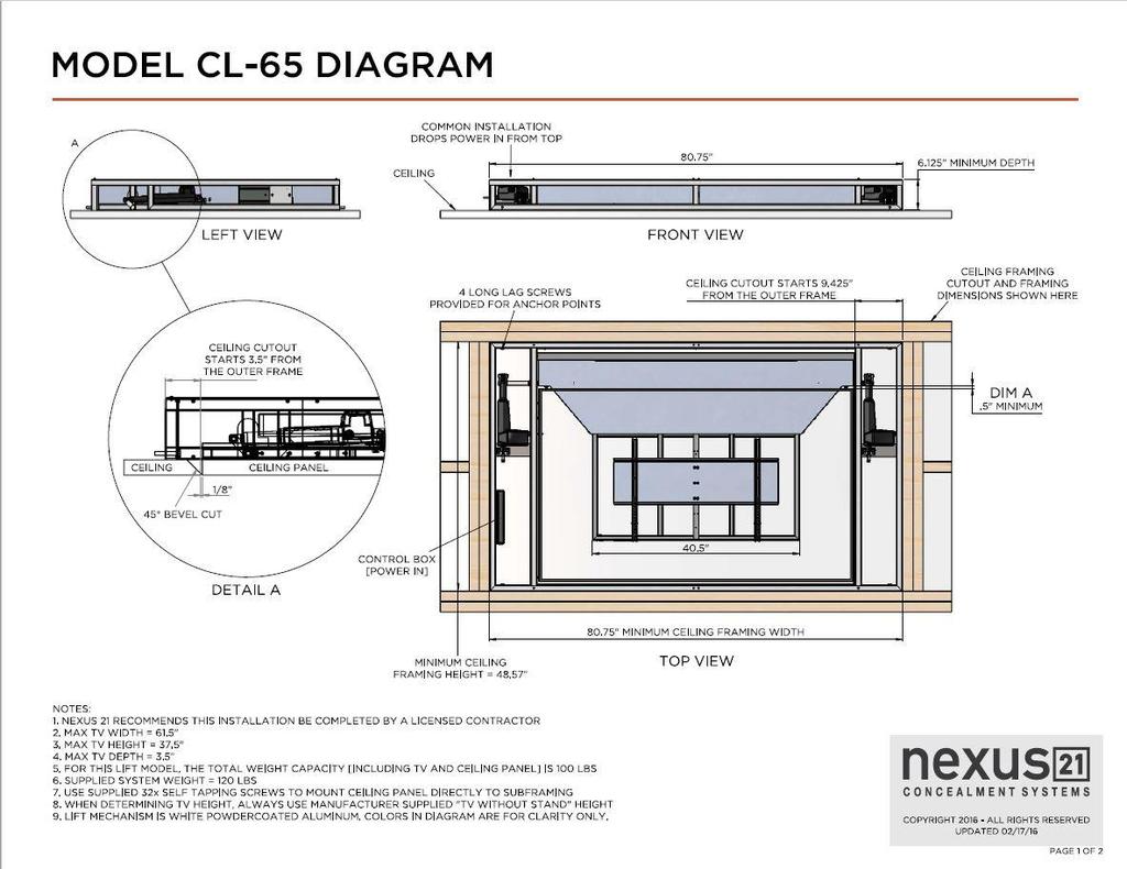
9 Step 7: Cut a panel using your preferred ceiling material using the Ceiling Panel measurements on the Dimensional Diagram for the CL-65. See page (12 & 13) for the CL-65 Dimensional Drawings. Step 8: Drill (20) #10-32 Self Tapping Pan Head Screws through the panel into the Sub-Frame to attach it. Step 9: The Installation is now complete. See Adjustments section to properly calibrate the Lift System. 8

10 Mounting the TV to the Lift Step 10: Attach the Vertical Mounting Bars to the TV using the screws found in the bag labeled TV Mounting Screws/Spacers. The length and size of the screw required will depend on whether the TV has a flat/unobstructed or irregular/obstructed back. 10 A Flat/Unobstructed Back Diagram A installation procedure: 1) Place the flat screen TV face down on a protected surface. 2) Position the Vertical Mounting Bars equidistant from the bottom and top of the TV, with the slots facing toward the top of the TV. 3) Using the four (4) Square Multi-Mount washers and the TV mounting screws selected from the bag, attach and tighten the hardware. DO NOT OVERTIGTHEN HARDWARE. DAMAGE TO TV MAY RESULT. B Irregular/Obstructed Back Diagram B installation procedure: 1) Place the flat screen TV face down on a protected surface. 2) Position the Vertical Mounting Bars equidistant from the bottom and top of the TV, with the slots facing toward the top of the TV. 3) Using the four (4) spacers needed, (4) Square Multi-Mount washers and the TV mounting screws selected from the bag, attach and tighten the hardware. The hardware will be used in this order (as shown in the diagram above): TV, Spacers, Vertical Mounting Bars, Square Multi-Mount Washers, TV Mounting Screws. DO NOT OVERTIGTHEN HARDWARE. DAMAGE TO TV MAY RESULT. 9
 Screen Locks, place one Screen Lock on a set of hooks for each Vertical Mount Bar.")
11 Step 11: Hang the TV on the Screen Back Plate that is attached to the Sub-Frame of the Lift System. Step 12: Insert both Screen Locks into both Vertical Mounting Bars. Using (2) Screen Locks, place one Screen Lock on a set of hooks for each Vertical Mount Bar. Using a Philips Head Screwdriver (not provided), tighten the Screen Lock set screws to prevent the Screen Lock from falling out of the slot on the Vertical Mounting Bar. Then use the 4mm T Handle to tighten the Screen Lock Screw to fasten the TV to the Screen Back Plate Set Screws 10


 You must loosen all four bolts before moving to Step 16.")
12 Adjustments To ensure the calibration is maintained, follow these steps only after the TV and Ceiling Panel have been mounted. Follow these steps to calibrate the Lift System: Step 13: Test the Lift by running it into the fully retracted position then determine one of the following: - Ceiling Panel sits flush, no adjustments are needed. - Ceiling Panel goes too far into the ceiling, follow the steps below to adjust it. - Ceiling Panel hangs to far below the ceiling, call for assistance. Step 14: Remove both of the Long Side Panels from each side of the Lift System. Step 15: Use provide 5/16 x 6 L Hex Key to loosen the (2) Socket Head Bolts located behind each Actuator on the left and right side of the Lift System. (Total of 4 Socket Head Bolts) You must loosen all four bolts before moving to Step Step 16: Loosen the Fine Adjustment Screw that is located behind each Actuator on the left and right side of the Lift System. NOTE: This will adjust the angle of the Sub-Frame so that when the lift retracts it will sit flush with the rest of the ceiling. It is recommended that you test each adjustment you make by running the lift up and checking where the panel rests when it is fully retracted. WARNING: Loosen the fine adjustment screws on left and right side by the same amount of turns. Do not tighten one side more than the other. Step 17: Tighten all (4) Socket Head Bolts from Step 15 and test the lift. Step 18: If the ceiling panel is still resting too high, repeat Step If it is hanging to low, repeat step 15, tighten the Fine Adjustment Screws, then repeat step
13 12
14 13

15 Connecting the Lift to your Home Control System 14
16 15


17 CL-65 IR Wiring Diagram Note: Ports A1 & A2 are interchangeable. Power Outlet IR Receiver Backup Switch 16
18 (Intentionally left blank) 17
19 (Intentionally left blank) 18
20
In-Ceiling Electric Motorized Front Projection Screen Evanesce Series. User s Guide
 In-Ceiling Electric Motorized Front Projection Screen Evanesce Series User s Guide Important Safety & Warning Precautions Make sure to read this user s guide and follow the procedures below. Caution: The
Electric Motorized Projection Screen PowerMax Tension Series
 Electric Motorized Projection Screen PowerMax Tension Series User s Guide Important Safety & Warning Precautions Make sure to read this user s guide and follow the procedures below. Caution: The screen
WID-DL74 WID-DL74 BLP WID. Designed for. Installation guide for workitdesk interactive table for. BrightLink Pro
 WID-DL74 WID-DL74 BLP WID Designed for BrightLink Pro Installation guide for workitdesk interactive table BrightLink Pro for Mounting the table unit 1 Unpack boxes 1 of 4 (Mobile base) and 2 of 4 (Motorized
READ ME FIRST. Touchstone TV Lift
 Whisper Lift II PRO 2 READ ME FIRST 1. After completing the unpacking and uncrating of the cabinet, you will find the Owner s Manual, TV, installation hardware, and the wireless remote all together and
#YourGearUpgraded. TV Stand Model EGTV1 INSTRUCTION MANUAL
 #YourGearUpgraded TV Stand Model EGTV1 INSTRUCTION MANUAL IMPORTANT SAFETY INSTRUCTIONS. READ ENTIRE MANUAL PRIOR TO USE. SAVE These INSTRUCTIONS Yea, the boring stuff...... but read it, so you don t jack
Electric Motorized Projection Screen Spectrum Tab-Tension Series User s Guide
 Electric Motorized Projection Screen Spectrum Tab-Tension Series User s Guide Important Safety Precautions Make sure to read this user s guide and follow the procedures below prior to screen operation.
V74 INSTRUCTIONS INSTALLATION VESA 700X400 FIXED WALL MOUNT ISSUE 002
 V74 VESA 700X400 FIXED WALL MOUNT INSTALLATION INSTRUCTIONS ISSUE 002 SAFETY DISCLAIMER IMPORTANT SAFETY INSTRUCTIONS BELOW WARNING: Failure to provide adequate structural strengthening, prior to installation
Electric Wall/Ceiling Projection Screen Saker Tab-Tension Series User s Guide
 Electric Wall/Ceiling Projection Screen Saker Tab-Tension Series User s Guide Important Safety & Warning Precautions Make sure to read this user s guide and follow the procedures below. Caution: The screen
Electric Wall/Ceiling Projection Screen Saker Series User s Guide
 Electric Wall/Ceiling Projection Screen Saker Series User s Guide Important Safety & Warning Precautions Make sure to read this user s guide and follow the procedures below. Caution: The screen s Black
Be sure to check the camera is properly functioning, is properly positioned and securely mounted, every time you operate your vehicle.
 Please read all of the installation instructions carefully before installing the product. Improper installation will void manufacturer s warranty. The installation instructions do not apply to all types
Important Safety & Warning Precautions
 Electric Motorized Projection Screen VMAX 2 Series User s Guide Important Safety & Warning Precautions Make sure to read this user s guide and follow the procedure below. Caution: The screen s Black Top
Starling Tab-Tension 2 Series
 Electric Wall/Ceiling Projection Screen Starling Tab-Tension 2 Series For: Spectra White FG and CineGrey 5D User s Guide Important Safety & Warning Precautions Make sure to read this user s guide and follow
CU103 User Manual. Contents
 [Note] The Photos of Light Engine and Control Unit in this manual are for reference only. The items may be different in actual package. Contents 1. PRECAUTIONS... 2 2. PACKAGE CONTENT... 4 3. PORT DESCRIPTION...
Q-TV2. User Manual. for Screens
 Q-TV2 User Manual for 30-42 Screens Contents Introduction 02 Safety Guidelines 03 Getting started 03 Potential Uses 04 Carton Contents 05 Q-TV2 Controls 05 Remote Fixings 06 Fixing Rails 07 Fitting Q-TV2
Installation Note. Agilent 89441A Option AYC Installation Kit
 Installation Note Agilent 89441A Option AYC Installation Kit Part Number: 89441-90074 Printed in USA February 2002 Notice. The information contained in this document is subject to change without notice.
MY-HITE ADJUSTABLE TABLE
 MY-HITE ADJUSTABLE TABLE Corner T Leg Base Model Number : FCNAHBT Please Read Instructions Before Use ASSEMBLY INSTRUCTIONS ALL WORKSTYLES WELCOME Thank you for choosing Friant. We appreciate the trust
Cellular Signal Booster
 Drive 4G-X Cellular Signal Booster THE ALUMINUM CASING OF YOUR SIGNAL BOOSTER!! WILL ADJUST TO THE TEMPERATURE OF ITS ENVIRONMENT, BUT IS DESIGNED TO PROTECT THE SIGNAL BOOSTER TECHNOLOGY. FOR EXAMPLE,
Electric Motorized Projection Screen Spectrum Series
 Electric Motorized Projection Screen Spectrum Series User s Guide 1 Important Safety & Warning Precautions Make sure to read this user s guide and follow the procedure below. Caution: The screen s Black
USER S MANUAL. Save this manual for future reference. For a digital version of this manual, visit
 TM USER S MANUAL Save this manual for future reference. For a digital version of this manual, visit www.mylifter.com/installation. 4 5 TABLE OF CONTENTS 4 INSTALLING THE PULLEY SYSTEM FOR LIFTING 100
INSTALLATION GUIDE. Axle Weighing Truck Scale. 60,000 lb x 20 lb Factory Calibrated Includes Pre-interfaced Wireless Remote LED Scoreboard Displays
 INSTALLATION GUIDE 60,000 lb x 20 lb Factory Calibrated Includes Pre-interfaced Wireless Remote LED Scoreboard Displays V 1.0 OVERVIEW TOOLS REQUIRED Forklift and block Prybar Wrenches: #8 allen wrench,
I1000M Rough-In Instructions
 I1000M Rough-In Instructions Thank you for purchasing an Intrasonic Technology product. Our products are built to provide you with years of high quality sound. If you need assistance with the installation
8753E, 8753ET, and 8753ES Network Analyzer Option 1D5 High Stability Frequency Reference Upgrade Kit. Applicable Upgrade Kit Model Number
 Installation Note 8753E, 8753ET, and 8753ES Network Analyzer Option 1D5 High Stability Frequency Reference Upgrade Kit Network Analyzer Model Number 8753E 8753ET 8753ES Applicable Upgrade Kit Model Number
Circulating Feed Delivery System Installation Instructions for Model 55, 75, 90, & HMC FLEX-AUGER Feed Delivery Systems
 Circulating Feed Delivery System Installation Instructions for Model 55, 75, 90, & HMC FLEX-AUGER Feed Delivery Systems April 02 Chore-Time Warranty Chore-Time Equipment, a division of CTB, Inc., ("Chore-Time")
PRJTPFL inch PRJTPFL inch PRJTPFL inch. Fixed Wall Mount Projector Screen. Universal Home/Office Projector Viewing Display
 PRJTPFL102-100 - inch PRJTPFL112-110 - inch PRJTPFL122-120 - inch Fixed Wall Mount Projector Screen Universal Home/Office Projector Viewing Display Be sure to read this manual before use so you will know
M1, M2GO and M2PC MIDI PCB Module Installation Guide SMPTE PCB Module Installation Guide
 M1, M2GO and M2PC MIDI PCB Module Installation Guide SMPTE PCB Module Installation Guide Author Part number Date Matthias Hinrichs/Chris Foblets 35000620-B 20.06.2012 This guide is also available for download
Electric Wall/Ceiling Projection Screen Saker Plus Series User s Guide
 Electric Wall/Ceiling Projection Screen Saker Plus Series User s Guide Important Safety & Warning Precautions Make sure to read this user s guide and follow the procedures below. Caution: The screen s
2000i. Projector Replacement Guide. for Projector Replacement Kits. NEC MT1060R ( ) and NEC MT860R ( ) Interactive Whiteboard
 and NEC MT860R ( ) Interactive Whiteboard") 2000i Interactive Whiteboard Projector Replacement Guide for Projector Replacement Kits NEC MT1060R (03-00043) and NEC MT860R (03-00041) 99-00496-00 Rev A0 FCC Warning This equipment has been tested and
2000i Interactive Whiteboard Projector Replacement Guide for Projector Replacement Kits NEC MT1060R (03-00043) and NEC MT860R (03-00041) 99-00496-00 Rev A0 FCC Warning This equipment has been tested and
Website: Tel: ADDRESS: 6475 Las Positas Rd. Livermore, CA Item No. E5B/E5S Installation Guide
 Website: www.flexispot.com Tel: -855-4-808 ADDRESS: 6475 Las Positas Rd. Livermore, CA 9455 Item No. E5B/E5S Installation Guide Specifications Step Column 3 Max. Weight Capacity 0 Ibs (00 kg) Speed 38mm/s
Operating Manual. Automated Gear. Apollo Design Technology, Inc Fourier Drive Fort Wayne, IN USA
 Operating Manual Automated Gear Apollo Design Technology, Inc. 4130 Fourier Drive Fort Wayne, IN 46818 USA PH: +01(260)497-9191 FX: +01(260)497-9192 www.apollodesign.net 11-25-09 5-6 POWERING UP THE RIGHT
QCA9-33 Active Combiner
 Product Manual QCA9-33 Active Combiner April 13, 2012 Table of Contents Table of Contents... 2 Overview... 3 Specifications... 4 Installation... 5 Basic Setup... 5 16-Channel Operation... 5 16-64 Channel
HD Digital Set-Top Box Quick Start Guide
 HD Digital Set-Top Box Quick Start Guide Eagle Communications HD Digital Set-Top Box Important Safety Instructions WARNING TO REDUCE THE RISK OF FIRE OR ELECTRIC SHOCK, DO NOT EXPOSE THIS PRODUCT TO RAIN
QDA4-44 RF Amp/Combiner
 Product Manual QDA4-44 RF Amp/Combiner May 17, 2012 Table of Contents Table of Contents... 2 Overview... 3 Specifications... 4 Installation... 5 Basic Setup... 5 Rack Mounting... 6 RK2 Dual Rack Kit with
Install Guide Incredible Technologies, Inc. All Rights Reserved
 Install Guide 2015 Incredible Technologies, Inc. All Rights Reserved Preface Using this Guide The following icons are used to highlight specific areas of interest and to indicate when extreme caution is
2178-L/S Series Fiber Optic Splice Case with Gasket
 2178-L/S Series Fiber Optic Splice Case with Gasket Instructions for: 2178-S Splice Case 2178-LS Splice Case 2178-LL Splice Case 2181-LS Cable Addition Kit May 1997 34-7041-9949-5-A 1 Table of Contents
ATTACHING & REMOVING THE BASE
 TV53DB ATTACHING & REMOVING THE BASE 1. To install or remove the neck, screw in or remove the 4 screws indicated in the picture. 2. To install the base, place the display unit flat on a table. Afterwards
WINEGARD. TRAV LER Automatic Multi-Satellite TV Antenna. Model SK-3003 DIRECTV TRIPLE FEED INSTALLATION MANUAL. Made in the U.S.A.
 WINEGARD TRAV LER Automatic Multi-Satellite TV Antenna Model SK-3003 DIRECTV TRIPLE FEED MANUAL Made in the U.S.A. SK-3003 Winegard Company 3000 Kirkwood St. Burlington, IA 52601-2000 319/754-0600 FAX
Component Video + Analog/Digital Audio Wall Plate (6-RCA) AT80COMP7
 AT80COMP7") Component Video + Analog/Digital Audio Wall Plate (6-RCA) AT80COMP7 User Manual www.atlona.com TABLE OF CONTENTS 1. Introduction 2 2. Applications 2 3. Specifications 2 4. Installation 2 5. Safety Information
Component Video + Analog/Digital Audio Wall Plate (6-RCA) AT80COMP7 User Manual www.atlona.com TABLE OF CONTENTS 1. Introduction 2 2. Applications 2 3. Specifications 2 4. Installation 2 5. Safety Information
Tension Electric Screen. CineTension Series. Users Guide USER S GUIDE. Rev. 1.1
 Tension Electric Screen CineTension Series Users Guide USER S GUIDE IMPORTANT SAFETY INSTRUCTIONS Please read this guide prior to installation. Make sure the current rating is equal to the appliance rating
DREAMOC DIAMOND 4K - ASSEMBLY GUIDE VERSION ORIGINAL ASSEMBLY GUIDE
 DREAMOC DIAMOND 4K - ASSEMBLY GUIDE VERSION 1.2 - ORIGINAL ASSEMBLY GUIDE It is important to read this assembly guide before using the Dreamoc Diamond, and to follow advices and instructions on safety,
Model#: IN-DI2MIRF 2MP Indoor Dome with True Day/Night, IR, Basic WDR, Fixed lens
 Model#: IN-DI2MIRF 2MP Indoor Dome with True Day/Night, IR, Basic WDR, Fixed lens Hardware User Manual (PoE) Ver.2013/01/17 Table of Contents 0. Precautions 3 1. Introduction 4 Package Contents...4 Features
FOSC 450 C6 and D6 Closures
 FOSC 450 C6 and D6 Closures I N S T A L L A T I O N I N S T R U C T I O N Fiber Optic Splice Closure 1. General Product Information The FOSC 450 C6 and D6 fiber optic splice closures use compressed gel
Circulating Feed Delivery System Installation Instructions for Model 55, 75, 90, & HMC FLEX-AUGER Feed Delivery Systems
 Circulating Feed Delivery System Installation Instructions for Model 55, 75, 90, & HMC FLEX-AUGER Feed Delivery Systems MA773-06 5/99 May 1999 Chore-Time Warranty Chore-Time Equipment warrants each new
LIGHT COPILOT II. elationlighting.com Internet:
 LIGHT COPILOT II E-mail: info@ elationlighting.com Internet: http://www.elationlighting.com 1 Introduction Thank you for your purchase of the LIGHT COPILOT II. The LIGHT COPILOT II is an intelligent lighting
Extender w/ RS-232 and 2-way IR
 Extender w/ RS-232 and 2-way IR GTB-UHD2IRS-ELRPOL-BLK User Manual Release A3 Important Safety Instructions 1. Read these instructions. 2. Keep these instructions. 3. Heed all warnings. 4. Follow all instructions.
PNP300 / PNP300UN / PNP350
 DOCUMENT NUMBER 400-0114-003 / UN / PNP350 Pop N Plug Slim INTERCONNECT BOX USER'S GUIDE TABLE OF CONTENTS Page PRECAUTIONS / SAFETY WARNINGS...2 GENERAL...2 INSTALLATION...2 CLEANING...2 ABOUT YOUR /300UN/350...3
User Instructions. 16 SCB Sync Station.
 User Instructions 16 SCB Sync Station Contents Overview... 1 Specifications... 1 Compliance and approvals... 2 Safety instructions... 3 Set up... 4 How to charge multiple devices... 4 How to synchronize
OPERATION AND MAINTENANCE MANUAL
 OPERATION AND MAINTENANCE MANUAL SERIAL NUMBER CUSTOMER: SALES REP.: CONTENTS Mixer Installation / Assembly / Dimension Drawings Safety... 1 Customer Service Contact... 1 Initial Inspection... 2 Installation...2
Audio. Extender. for HDMI GBT-HDBT-POL. User Manual. Release A7
 Audio 3GSDI Embedder Extender for HDMI GBT-HDBT-POL w/pol User Manual Release A7 Extender for HDMI w/pol Important Safety Information 1. Read these instructions. 2. Keep these instructions. 3. Heed all
Evolution Digital HD Set-Top Box Important Safety Instructions
 Evolution Digital HD Set-Top Box Important Safety Instructions 1. Read these instructions. 2. Keep these instructions. 3. Heed all warnings. 4. Follow all instructions. 5. Do not use this apparatus near
OWNER'S MANUAL SIGNAL COMMANDER
 OWNER'S MANUAL SIGNAL COMMANDER THIS MANUAL CONTAINS INSTRUCTIONS FOR: LPDA 100 - INSTALLATION - OPERATION - TROUBLESHOOTING - EXPLODED PARTS DIAGRAM - WARRANTY AntennaTek, Inc. 425 S. Bowen, # 4 Longmont,
FOSC-600 C and D I N S T A L L A T I O N I N S T R U C T I O N
 FOSC-600 C and D I N S T A L L A T I O N I N S T R U C T I O N In-line and butt version Cold applied re-usable fiber optic closure Contents 1 Introduction 1.1 Product description 1.2 Capacity 2 General
Additional Information for Using Sony Wall-Mount Bracket (SU-WL500)
") A-E96-100-12(1) Additional Information for Using Sony Wall-Mount Bracket (SU-WL500) Compatible TV models for this Wall-Mount Bracket information: XBR-84X905/84X900 XBR-65HX957/65HX955/65HX950/55HX957/55HX955/55HX950
A-E96-100-12(1) Additional Information for Using Sony Wall-Mount Bracket (SU-WL500) Compatible TV models for this Wall-Mount Bracket information: XBR-84X905/84X900 XBR-65HX957/65HX955/65HX950/55HX957/55HX955/55HX950
Setup Guide. Read me BefoRe unpacking!
 Setup Guide Read me BefoRe unpacking! Package Contents In The Replicator package The Replicator SD card (in The Replicator SD card slot) In the Accessory Box found within The Replicator frame Single or
ZVOX AccuVoice TV Speaker MODEL AV150.
 ZVOX AccuVoice TV Speaker MODEL AV150 www.zvoxaudio.com READ THIS FIRST Important Safety Instructions For ZVOX Audio System WARNING TO PREVENT FIRE OR SHOCK HAZARD, DO NOT EXPOSE THIS APPLIANCE TO RAIN
Metal and Glass TV Stand for TVs up to 65 or 110 lbs. NS-HMG1856
 USER GUIDE Metal and Glass TV Stand for TVs up to 65 or 110 lbs. NS-HMG1856 SAFETY INFORMATION AND SPECIFICATIONS...2 PACKAGE CONTENTS: PARTS...3 PACKAGE CONTENTS: HARDWARE...4 ASSEMBLY INSTRUCTIONS...5
HDTV Supply Inc. reserves the right to make changes in the hardware, packaging and any accompanying documentation without prior written
 HDMI Matrix (Router Type) Model No. HDTVMX0404313 HDTV Supply, Inc Features Easy to use: install in seconds, no need for setting. Allows up to four HDMI audio/video devices to be independently switched
2178 Fiber Optic Splice Case and 2181 Cable Addition Kit
 2178 Fiber Optic Splice Case and 2181 Cable Addition Kit Instructions January 1994 Issue 1, 34-7029-6387-6 1 2 Contents: 1.0 General... 4 2.0 Specifications... 4 3.0 Kit Contents... 5 SECTION 1: 2178 Splice
TracVision R6DX Installation Guide
 TracVision R6DX Installation Guide These instructions explain how to install the TracVision R6DX satellite TV antenna system on an RV or motor coach. Complete instructions on how to use the system are
PNP300 & PNP350 POP N PLUG SLIM INTERCONNECT BOX USER S GUIDE
 The is shown above. MANUAL PART NUMBER: 400-0114-004 & PNP350 POP N PLUG SLIM INTERCONNECT BOX USER S GUIDE TABLE OF CONTENTS Page PRECAUTIONS / SAFETY WARNINGS... 2 GENERAL...2 HANDLING...2 CLEANING...2
Luxus A / SR-1 Electriscreen
 Luxus A / SR-1 Electriscreen O W N E R S M A N U A L To the Owner Installation Instructions Operating the Screen LXSR-0903 Maintenance T O THE INSTALLER: BE SURE TO LEAVE THIS MANUAL WITH THE OWNER. Printed
INSTALLATION INSTRUCTIONS FOR
 INSTALLATION INSTRUCTIONS FOR MODEL 2240LED www.sportablescoreboards.com 1 Table of Contents 8 X 7 INDOOR SCOREBOARD... 3 THE SCOREBOARD SYSTEM SHOULD INCLUDE THE FOLLOWING PARTS:... 3 INSTRUCTIONS FOR
Caution. Hanging the Screen:
 Installation Instructions for Laminar and Laminar XL Projection Screens Caution 1. Read Instructions through completely before proceeding; keep them for future reference. Follow these instructions carefully.
Winch Adjustable Feed Level Tubes for the Adult Turkey Feeder Installation & Operator s Instruction Manual MF /99
 Winch Adjustable Feed Level Tubes for the Adult Turkey Feeder Installation & Operator s Instruction Manual MF7-8 6/99 June 999 MF7B Chore-Time Warranty Winch Adjustable Feed Level Tubes for ATF Chore-Time
User Manual. Tensioned Screens. Website: Tel:
 User Manual Tensioned Screens Website: www.luxburgvisual.com Email: support@luxburgvisual.com Tel: 0044 207 237 4842 Table of Contents SAFETY INFORMATION... 3 IMPORTANT SAFETY INSTRUCTION... 3 SETTING
SCIR. Infrared Illuminator Powerful Indoor/Outdoor IR Spotlight SCIR
 SCIR Infrared Illuminator Powerful Indoor/Outdoor IR Spotlight The NetMedia SCIR Infrared (IR) Illuminator provides night vision for IR (850nm) sensitive cameras. It enables cameras such as NetMedia s
ENGINEERING COMMITTEE Interface Practices Subcommittee AMERICAN NATIONAL STANDARD ANSI/SCTE
 ENGINEERING COMMITTEE Interface Practices Subcommittee AMERICAN NATIONAL STANDARD ANSI/SCTE 102 2010 Cable Retention Force Testing of Trunk & Distribution Connectors NOTICE The Society of Cable Telecommunications
SCREEN WINCH SYSTEM INSTALLATION MANUAL FOR SCREENS UP TO 300 cm. of width
 SCREEN WINCH SYSTEM INSTALLATION MANUAL FOR SCREENS UP TO 300 cm. of width Before installing the screen winch system, please read the following instructions carefully: The screen winch system must be used
PRODUCT MANUAL : 1x8 Splitter/Extender : Receiver (Sold Separately)
") PRODUCT MANUAL Product Name: S-VGA Splitter/Extenders over Category 5e/Cat6 Cable Part Numbers: 90-12116: 1x2 Splitter/Extender 90-12112: 1x8 Splitter/Extender 90-12113: Receiver (Sold Separately) WARNING:
PRODUCT MANUAL Product Name: S-VGA Splitter/Extenders over Category 5e/Cat6 Cable Part Numbers: 90-12116: 1x2 Splitter/Extender 90-12112: 1x8 Splitter/Extender 90-12113: Receiver (Sold Separately) WARNING:
SCREEN WINCH SYSTEM INSTALLATION MANUAL FOR SCREENS FROM 300 cm. UP TO 450 cm. of width
 SCREEN WINCH SYSTEM INSTALLATION MANUAL FOR SCREENS FROM 300 cm. UP TO 450 cm. of width Before installing the screen winch system, please read the following instructions carefully: The screen winch system
AS-300D Series Smart Bench Scales Owner s Manual
 DETE CTO A Division of Cardinal Scale Manufacturing Co. AS-300D Series Smart Bench Scales Owner s Manual 8527-M214-O1 Rev B 01/03 PO BOX 151 WEBB CITY, MO 64870 417-673-4631 Printed in USA INTRODUCTION
APSPB PUSH BUTTON ZERO Installation Manual
 APSPB PUSH BUTTON ZERO Installation Manual CARDINAL SCALE MFG. CO. 8527-0579-0M Rev A 203 E. Daugherty, Webb City, MO 64870 USA Printed in USA 12/14 Ph: 417-673-4631 Fax: 417-673-2153 www.detectoscale.com
Register your product and get support at SDV5122/27. EN User manual
 Register your product and get support at www.philips.com/welcome SDV5122/27 User manual Contents 1 Important 4 Safety 4 Notice for USA 5 Notice for Canada 5 Recycling 6 English 2 Your SDV5122 7 Overview
In-Wall Control Mount for ipod Touch
 In-Wall Control Mount for ipod Touch INTRODUCTION The Mirage KP-iOS is an in-wall system that allows ipod touch (4th generation) to become a semi-permanent fixture in your wall. The system allows you to
SCREEN WINCH SYSTEM INSTALLATION MANUAL FOR SCREENS UP TO 300 cm. of width
 SCREEN WINCH SYSTEM INSTALLATION MANUAL FOR SCREENS UP TO 300 cm. of width Before installing the screen winch system, please read the following instructions carefully: The screen winch system must be used
Assembling and Mounting the Presentation Display, Speakers, Speaker Screens, and Table Door
 CHAPTER 8 Assembling and Mounting the Presentation Display, Speakers, Speaker Screens, and Table Door July 13, 2012, This document provides you with the procedures you perform to assemble and mount the
Zero-G. Owner s Manual. External Mount INSTALLERS: PLEASE LEAVE THIS MANUAL WITH THE OWNER.
 Zero-G Owner s Manual External Mount INSTALLERS: PLEASE LEAVE THIS MANUAL WITH THE OWNER. APPLY S/N STICKER HERE LIMITED ONE YEAR WARRANTY ON SCREEN INNOVATIONS PRODUCTS Screen Innovations warrants its
Operation Manual VMS 3.0 Video System
 Operation Manual VMS 3.0 Video System for the AlterG Anti-Gravity Treadmill 1 This manual covers operation procedures for the following AlterG products: AlterG Video System model VMS 3.0 NOTE: The following
Stand Alone Serenity, Light, Sound, Rain Head
 Installation Manual For Tutorials and Troubleshooting visit www.thermasol.com/solutions SASC-XX, SAST-XX, SASMR-XX, SAST-XX Stand Alone Serenity, Light, Sound, Rain Head OVER 55 YEARS OF STEAM SHOWER INNOVATION
COMPOSITE VIDEO (BNC) TO VGA VIDEO FORMAT CONVERTER AND SCALER AT-RGB110
 TO VGA VIDEO FORMAT CONVERTER AND SCALER AT-RGB110") User Manual COMPOSITE VIDEO (BNC) TO VGA VIDEO FORMAT CONVERTER AND SCALER AT-RGB110 TABLE OF CONTENTS 1. Introduction... 2 2. Package Contents... 2 3. Features... 2 4. Specification... 2 5. Panel Description...
User Manual COMPOSITE VIDEO (BNC) TO VGA VIDEO FORMAT CONVERTER AND SCALER AT-RGB110 TABLE OF CONTENTS 1. Introduction... 2 2. Package Contents... 2 3. Features... 2 4. Specification... 2 5. Panel Description...
OWNER'S MANUAL SIGNAL COMMANDER
 OWNER'S MANUAL SIGNAL COMMANDER THIS MANUAL CONTAINS INSTRUCTIONS FOR: LPDA 200 - INSTALLATION - OPERATION - TROUBLESHOOTING - EXPLODED PARTS DRAWING - WARRANTY AntennaTek, Inc. 425 S. Bowen, #4 Longmont,
ACCESSORIES MANUAL PART NUMBER: PRODUCT REVISION: 1 TNP100. Tilt N Plug Interconnect Box USER'S GUIDE
 MANUAL PART NUMBER: 400-0091-001 PRODUCT REVISION: 1 TNP100 Tilt N Plug Interconnect Box USER'S GUIDE INTRODUCTION Your purchase of the TNP100 Tilt N Plug Interconnect Box is greatly appreciated. We are
TeamWork Kits Installation Guide
 TX 0 RX COM +5V APARATUS US TeamWork Kits Installation Guide TeamWork 400 and TeamWork 600 Kits The TeamWork 400 and TeamWork 600 kits consist of an HDMI switcher, system controller, Cable Cubby, and cables
Extender for HDMI over one CAT5
 1080P Extender for HDMI over one CAT5 GTV-HDBT-CAT5 User Manual gefentv.com ASKING FOR ASSISTANCE Technical Support: Telephone (818) 772-9100 (800) 545-6900 Fax (818) 772-9120 Technical Support Hours:
Safety Information. Camera System. If you back up while looking only at the monitor, you may cause damage or injury. Always back up slowly.
 Table of Contents Introduction...3 Safety Information...4-6 Before Beginning Installation...7 Installation Guide...8 Wiring Camera & Monitor...9-10 Replacement Installation Diagram...11 Clip-On Installation
Extender for HDMI. gefentoolbox.com GTB-HDBT-POL GTB-HDBT-POL-BLK. User Manual
 Extender for HDMI w/pol GTB-HDBT-POL GTB-HDBT-POL-BLK User Manual gefentoolbox.com ASKING FOR ASSISTANCE Technical Support: Telephone (818) 772-9100 (800) 545-6900 Fax (818) 772-9120 Technical Support
Grandbeing. HDMI Matrix (Router Type) Features
 Features") HDMI Matrix (Router Type) MX0404-310 Operating Instructions Grandbeing Model No. MX0404-310(P/N of this Instructions is INSMX0404-310) Features Easy to use: install in seconds, no need for setting. Allows
HDMI Matrix (Router Type) MX0404-310 Operating Instructions Grandbeing Model No. MX0404-310(P/N of this Instructions is INSMX0404-310) Features Easy to use: install in seconds, no need for setting. Allows
HD POWERLINK SYSTEM USER MANUAL HDP100
 HD POWERLINK SYSTEM USER MANUAL HDP100 CAUTION RISK OF ELECTRIC SHOCK. DO NOT OPEN. Caution: To reduce the risk of electric shock, do not remove cover (or back). No user serviceable parts inside. Refer
Introduction. Introduction
 Introduction Introduction Note: In this user guide Pronto is used for both ProntoPro and Pronto remote controls. RFX6000 is compatible with TSU3000 and TSU6000. About the RFX6000 Most remote control systems
WINEGARD INSTALLATION MANUAL. Model GM Carryout Ladder Mount for mounting pipes with outer diameters between 1 to 1-1/8
 WINEGARD INSTALLATION MANUAL Model GM-3000 Carryout Ladder Mount for mounting pipes with outer diameters between 1 to 1-1/8 WARNING: DO NOT USE THE LADDER MOUNT AS A STEP! NOT INTENDED FOR USE WITH THE
SLiC Fiber Aerial Closure System
 3 SLiC Fiber Aerial Closure System SLFC 533-SP SLFC 533-TS SLFC 733-SP Instructions May 2005 78-8135-4502-3-B N C H E S R A N G E M IL L IM E T E R S.4 10.6.8 A B C 15 20 I 1.0 Kit Contents Note: Examine
LED TV MODEL NO.: NE22K5BG. Please read this manual carefully before installing and operating the TV. Keep this manual handy for further reference
 LED TV USER MANUAL MODEL NO.: NE22K5BG IMPORTANT Please read this manual carefully before installing and operating the TV. Keep this manual handy for further reference Table Of Contents Preparations Guide
Operating Manual. CAT5 Audio Balun KD-CAT5XST
 CAT5 Audio Balun Key Digital, led by digital video pioneer Mike Tsinberg, develops and manufactures high quality, cutting-edge technology solutions for virtually all applications where Operating Manual
 Register your product and get support at www.philips.com/welcome SWS3435S/27 SWS3435H/37 EN User manual Contents 1 Important 4 Safety 4 English 2 Your SWS3435 6 Overview 6 3 Installation 7 Connect the
CAUTION RISK OF ELECTRIC SHOCK NO NOT OPEN
 Evolution Digital HD Set-Top Box Important Safety Instructions 1. Read these instructions. 2. Keep these instructions. 3. Heed all warnings. 4. Follow all instructions. 5. Do not use this apparatus near
NewScope-7A Operating Manual
 2016 SIMMCONN Labs, LLC All rights reserved NewScope-7A Operating Manual Preliminary May 13, 2017 NewScope-7A Operating Manual 1 Introduction... 3 1.1 Kit compatibility... 3 2 Initial Inspection... 3 3
Assembly instructions
 Assembly instructions Model: MXR0024/KIT TV Aerial - 18 Element Kit Contact: Helpline: +44 (0)1553 811000 Email: support@maxview.co.uk Web: www.maxview.co.uk Maxview reserve the right to change specifications
CNK221/241/261/321/341/361 Cable-Nook Jr. User s Guide
 Cable-Nook Jr. Welcome! We greatly appreciate your purchase of the Cable-Nook Jr. Interconnect Box. We are sure you will find it reliable and simple to use. Superior performance for the right price, backed
Elite Silvermax Series
 Electric Projection Screen Elite Silvermax Series USER S GUIDE IMPORTANT SAFETY INSTRUCTIONS Please read this guide prior to installation. Make sure the current rating is equal to the appliance rating
Installation Manual Original Instructions - IW4001
 Installation Manual Original Instructions - IW4001 Installation Manual 1 General Operator and Supervisor Information Signal Word Definition Signal Word Panel Table of Contents Operator and Supervisor Information
ACCESSORIES MANUAL PART NUMBER: TNP500. Universal Tilt N Plug Interconnect Box USER'S GUIDE
 MANUAL PART NUMBER: 400-0091-003 TNP500 Universal Tilt N Plug Interconnect Box USER'S GUIDE INTRODUCTION Your purchase of the TNP100 Tilt N Plug Interconnect Box is greatly appreciated. We are sure you