Carrier-band Network Monitor
|
|
|
- Michael Rolf Simmons
- 6 years ago
- Views:
Transcription
1 Operating Manual Carrier-band Network Monitor Model CBM-1 Installation 1 Introduction 3 Operation 4 Operation Modes 5 All-Station Mode 5 Stand-Alone Station Measurement 7 Individual Station Mode 8 Inactive Station Mode 9 Loose Connection Detection 10 Signal Viewing 10 Reflection 12 Status and Setting Mode 14 Using the Monitor Effectively 17 Computer Enhanced Operation 18 Appendices: A. Address Display Formats 19 B. Battery 19 C. Error Messages 20 D. Network Operation Overview 20 E. Measurement Summary 22 F. Accessories, Options, and Specifications 25 Warranty 27
2 Page 1 Installation This equipment may be connected to mains/line voltages of Volt AC at 47-63Hz. The power consumption is less than 20 Watts. Power is attached to the unit through a standard IEC- 325 power receptacle. There is no voltage selection device, this unit uses a universal input power supply. There are no special mounting requirements for this product. The unit has a tilt handle which can be used to elevate either the front or rear of the unit to allow better visibility of the front panel during operation. There are no means to electrically disconnect this device from the mains/line supply other than to remove the mains plug. The input is fused with a self-resetting solid state device that requires no user intervention for proper operation. Controls and Connectors Front Panel Controls/Connectors The Controls for the unit are membrane switches. The PWR switch is a soft switch - the microprocessor controls the internal solid state switch. All other switches are in a matrix scanned by the microprocessor for control of the unit. There are two front panel connectors which are 75 Ohm BNC style connectors. The signal to be applied to these connectors is a standard IEEE (IEC ) token bus signal of a level not to exceed +70 dbmv. The display is a 20 character X 4 line LCD with an electroluminescent backlite panel. Normal instrument operation, settings and control is accomplished through the use of the display and front panel keys. Rear Panel Connections The rear panel has four Connectors. A power connector, an RS-232 connection, and two BNC's for observation of signals. These are described below: Power Connector - IEC-325 style. Input is Volts AC between 47 and 63 Hz. The power consumption is less than 20 Watts. RS-232 Connector- 9 pin "D" plastic. This connector provides for communication to the unit with baud rates from 300 to 9600 Baud. The connection can be used to control the unit with appropriate software, and is used to upgrade the Flash version of the unit when an upgrade is necessary. This connector and associated circuitry can be electrically isolated with the appropriate installed option for ground sensitive applications. TRIG Connector- BNC connector. Provides an output signal that is of" a duration of approximately 5 microseconds, and with an amplitude of approximately 5 Volts. The signal is from +5 Volts to ground and the falling edge is generated upon detection of the final end delimiter of a recognized signal. This signal is meant to drive a coax cable (50-75 Ohms) into a normal oscilloscope 1M Ohm input. This signal is driven by an approximately 75 Ohm source and if terminated in 75 Ohms, will result in about 1/2 the amplitude stated above.
3 Page 2 SIG. LEV. Connector- BNC connector. Provides an output signal that is either: 1. A logarithmic representation of the applied input signal of about 10 db per 100mv with 0 dbmv being near ground potential. Useful for checking signal levels, reflections, and noise sources, or 2. An output signal representative of the applied input signal amplified by 20 db to allow checking for distortion and noise. This signal is meant to drive a coax cable (50-75 Ohms) into a normal oscilloscope 1M Ohm input. This signal is also driven by a 75 Ohm source and if terminated in 75 Ohms, will result in 1/2 the amplitude stated above.
4 Page 3 INTRODUCTION The CBM-1 Monitor is a network diagnostic and maintenance tool for the IEEE (ISO ) token bus carrier-band network operating at 5 Mbit/s. It is used to observe network operation and make measurements while the network is active. The Monitor complements Relcom's CBT Tester that is used to install and check the network wiring system when the network is not operating. The Monitor is a passive network device that examines network activity but does not interfere with the networks operation in any way. It is a valuable management and maintenance tool for critical control networks that have to operate continuously. The Monitor is used to: List all the stations* active on the network s logical ring and note the stations that join or leave the network. Measure the signal level of each station and display its current and low signal level values. Measure the reflections on the network that indicate wiring problems. Measure the noise caused by external sources or grounding problems. These measurements verify good network operation or alert maintenance personnel about deteriorating network conditions so that steps can be taken to prevent network downtime or to help determine what has failed. The Monitor can optionally be connected through an RS-232 interface to either a local PC or through a modem to a remote PC. The Monitor software program on the PC can control the Monitor, display network measurements. save them and compare them to previous measurements. Figure 1. Monitor Measures Two Network Segments * "Stations" are also called "nodes" or "devices."

 Line 2 blank Line 3 indicates the remaining battery capacity.")
5 Page 4 OPERATION* The Monitor is controlled from the front panel: Figure 2. Front Panel Pressing the Monitor s PWR switch turns the Monitor either ON or OFF. The PWR switch has to be held for a little while. This prevents accidental contact from activating the switch. After power is turned on, the Monitor performs a self-check and momentarily indicates its status on the display: Figure 3. Power-up Test Line 1 shows if the self-test is OK or if the Monitor is defective. (See Error Messages) Line 2 blank Line 3 indicates the remaining battery capacity. (See "Battery" in the Appendix) Line 4 blank After the momentary display, the Monitor enters the All Station mode and begins to look for signals on input connector A. Once network signals have been found, the Monitor begins to acquire a list of all the stations participating in token passing on the network and makes signal and noise measurements. Pressing the A/B switch toggles which of the A or B inputs is selected for measurement and display. *The Monitor operation discussion assumes some knowledge of how the token passing bus network works. For a quick introduction, see the Network Operation Overview section.


6 Page 5 OPERATING MODES The MODE switch selects one of the Monitor; operating modes. Push the MODE switch down to get the next mode below. Push the MODE switch up to get the next mode above. Pushing the SET switch while in any one of the measurement modes will switch the Monitor to its Status and Setting mode. When in the status and setting mode, pushing the SET switch puts the Monitor back to the measurement mode it was previously in. Figure 4. Mode Selection All-Station Mode When the All-Station mode is first entered after powering up or after reset, the Monitor looks for stations active on the network on channel A. During this time, the display shows: Figure 5. Display While Looking If the Monitor cannot find any stations, it will display: Figure 6. Display if Not Connected to Network


7 Page 6 If there are stations operating on the network, the Monitor shows that it is acquiring stations: Figure 7. Display While Acquiring Stations After the Monitor has found all the stations, it displays a summary of its findings. The Monitor keeps making measurements and updating the display: Figure 8. Display of All-Station Mode Line 1 shows: The network segment being measured, A or B. The number of stations currently active in the logical ring. Most stations found on the logical ring during this measurement session. If the Active count is less than the Total station count, one or more stations have left the logical ring. The "+" sign is a changing symbol that indicates that the Monitor is actively making measurements and updating the display. Line 2 shows the minimum signal and which station has this level. The minimum signal should be greater than Line 3 shows if the Monitor detects a reflection and the station where it shows up the most. The amount of reflection can be examined by going to that station in the Individual Station mode. See the Reflection section for details. Line 4 shows the Noise level on the network wiring. The noise measurement is displayed in two ways. The bar graph shows the noise level as a moving bar. The bar has a rapid rise time and a slow decay so that noise bursts can be observed. Line 4 also shows the average noise level and the peak noise levels numerically. The average noise should be less than -10. Pressing the A/B switch changes the network segment being measured and displayed. NOTE: The signal reflection and noise measurements are particular to the place on the network where the Monitor is attached. If the Monitor is attached to a different place, the measurements are likely to be different.

8 Page 7 Stand-Alone Station Measurement The Monitor can make measurements on a stand-alone station before it is attached to the network. This is useful to see that the station has an adequate signal level, the station has a recognizable frame and the station s address will not conflict with other stations' addresses already on the network. In this test, the station is connected directly to the Monitor. A Stand-Alone station measurement is made when the Monitor cannot find token frames during the All-Station measurement. In that case the Monitor detects one station attempting to make contact with other stations. The Stand-Alone Station display will show: Figure 9. Display of Stand-alone Mode Line 1 shows the network segment examined and that only one station has been found. The "+" sign is a changing symbol that indicates that the Monitor is actively making measurements and updating the display. Line 2 shows the address of the station. (See Appendix A for the different types of address displays). Line 3 shows the signal level of the station. A signal output of +60 dbmv and above will show as +60. This level is adequate for attaching a station to the network. Line 4 shows the maximum noise and the average noise generated by the station. The average noise should be less than -15. When the station is attached directly to the Monitor, the Monitor cannot measure the station s signal level because it is too high. The Monitor only gives an indication that there is a high signal output. To make a more exact measurement of a station's signal level, connect the station and the Monitor to the drop ports of a tap. Figure 10. Precise Signal Measurement Configuration Be sure the two trunk ports of the tap are terminated. The tap attenuates the station s signal level by 40 db. If the station transmits at +64 dbmv, for example, the Monitor s measurement will be +24 dbmv. Note: The only front panel control that is operational during the Stand-alone measurement mode of operation is the power switch. All other controls are disabled. The only exit from this mode is by waiting for a timeout condition indicated by the display showing the "LOOKING" message. To

9 Page 8 do this, the input signal must be disconnected from the front panel for a period of time exceeding the selected timeout value. Reset Acquire Mode This mode of operation is provided to allow a quick method to clear all measurements and reacquire the station list. It resets all stored measurements for the selected channel. When troubleshooting cable problems, high noise peaks, low signal levels, and possible reflections may cause unusual out-of-range readings. Re-acquiring the channel gives a more realistic view of possible changes in the system. Individual Station Mode After the Monitor has acquired all the stations on the network, the Individual Station Mode provides information about a specific station: Figure 11. Display of Individual Station Mode Line 1 shows the network segment, A or B, followed by the Station Number. The Station Number is a number that the Monitor assigns to each station that the Monitor has detected on the network. The station with the highest network address is "1 ;' the station with the next lower address is "2;' etc. This station numbering is for user convenience so that a station can be identified by a single number rather than by the much longer network address. Line 1 also shows the number of stations active on the network at the time this mode was entered. A changing symbol indicates that the Monitor is actively making measure-merits on the selected station and updating the display. This is shown by the "+" sign above. Line 2 shows the stations address. Line 3 shows the present signal level and the lowest signal level recorded during this measurement session. Line 4 shows the present reflection level and the highest reflection level recorded during this measurement session. The reflection number should be less than 3. (For a detailed discussion, see Reflection below) To examine other stations, push the SELect switch. If the lower SELect switch is pushed, the next lower addressed station is displayed. If the upper SELect switch is pushed, the next higher addressed station is displayed. The station display "wraps'.' Pushing the upper SELect switch when the highest address station is displayed will get the lowest address station.


10 Page 9 Inactive Station Mode A station is called inactive if at one time it was part of the logical ring but now cannot be detected. In the All-Station mode this shows up as less stations active now than the total detected in the network. To find out which stations are inactive, push the Mode down switch twice to get to the Inactive Station Mode. Figure 12. Display of Inactive Station Line 1 shows that station 2 on channel A is inactive. Line 2 shows the station s address. Line 3 shows the past/current signal average and minimum. Line 4 shows the past/current average and maximum reflection. If the station becomes active and rejoins the network the "+" on the right side of the display changes. The list of inactive stations can be scrolled by the SELect switches. Figure 13, Display of Inactive History Line 2 shows that station 5 on channel A is being displayed. Line 3 shows the station s address. Line 4 shows that the station has left the logical ring 18 times. The inactive station history and all the other Monitor s current measurements can be cleared by pushing the Set switch and selecting the Clear option. Inactive Station mode works like the Individual Station mode in that the Monitor tries to detect communication from the selected station and display its signal and reflection. If the station is inactive, the last measurement results are displayed: By pushing the Mode down switch, the Monitor displays the inactivity history of the selected station. This is useful for long-term monitoring of intermittent problems.

11 Page 10 LOOSE CONNECTION DETECTION Defective or loose wiring can cause stations to drop off the network and come back on intermittently. To help locate these types of problems, the Monitor provides audio and visual indications: When a station leaves the logical ring, the Monitor sounds a long beep and slowly blinks the backlight of the display two times. When a station enters the logical ring, the Monitor sounds a short beep and blinks the display backlight two short times. The wiring problem can often be located by shaking the wiring and listening for the beeps or watching for the display to blink. SIGNAL VIEWING Signal from a selected station can be examined with an oscilloscope when the Monitor is in Individual Station mode. The signal is available on the connector labeled SIG. LEV. on the back of the Monitor. A negative going trigger is generated on the TRIG connector each time the selected station s token frames end delimiter is detected. A digital oscilloscope is recommended so that the signal can be examined before as well as after the trigger. Figure 14. Back of Monitor
12 Page 11 The signal at the SIG. s can be one of two types selectable in Status and Settings: Input The signal received by the Monitor is amplified by 20 db so that it resembles the signal on the trunk cable. This is useful for looking at the reflections and noise at the end of a frame or at distortions of the signal. For example: Figure 15. Input Signal The oscilloscope should be set to 100 mv/div, and 200 ns/div. The trigger should be on the falling edge. LogAmp shows the signal envelope. The envelope level is logarithmic. Each 13 mv variation on the oscilloscope screen represents about ] db of signal variation. This makes noise appear to be larger than it really is. For example, if the signal is, say, 15 dbmv and the noise is -20 dbmv, the display would look like: Figure 16. LogAmp Signal The scope settings should be 100 mv/div and 2 us/div. The trigger should be on the falling edge.
13 Page 12 REFLECTION Normally, when a station stops transmitting a frame, the signal from the station dies out quickly. If there is a cable system fault, there is a residual signal (a reflection). This may be caused by a cable fault, a bad terminator or an unterminated tap. In the All Station mode the Monitor looks for this signal after a station has stopped transmitting. If the Monitor can detect the reflection, the Ail Station display will show the station after whose transmission this residual signal is most detectable. To get an indication about the severity of the reflection, go to the Individual Station mode and select that station. The 4th line of the display shows the current reflection level and the maximum reflection level measured. Reflection severity is shown as dbs above 0 dbmv. Reflections below 3 are not important. Reflections greater than that should be examined with a scope. To look at reflections, put the Monitor in the Individual Station mode and select the station after whose transmission the reflection is to be examined. Connect an oscilloscope to the SIG. LE-- s. connector and trigger (negative going edge) from the TRIG. connector of the Monitor. Normally, when there are no reflections, the signals look like the ones shown in Figure 15 and Figure 16. If there is a trunk cable discontinuity such as a loose trunk terminator, it will cause a reflection, that is, an echo. Consider this example: Figure 17. Example Network Two stations are on a network as shown in Figure 17. At station 2, the trunk cable terminator is loose. When the Monitor triggers the scope after station 1 transmission, the signal and reflection look like that shown in Fig. 18. Figure 18. Signal and Reflection From Station 1
14 Page 13 When the Monitor triggers the scope after Station 2 s transmission, the signal and reflection look like that shown in Fig. 19. Figure 19. Signal and Reflection From Station 2 Note that the signal from Station 2 is much smaller than that from Station 1 because of cable attenuation. Also note that the reflection at Station 2 cannot be seen because the discontinuity, the loose terminator, is at Station 2. The duration of the reflection indicates the distance the selected station is from the discontinuity. The station furthest from the cause of the reflection is the one that shows the greatest duration of the reflection. The location of the discontinuity can be estimated from the length of the signal reflection. Consider the LogAmp signal from Station 1: Figure 20. LogAmp Signal of Station 1. In Figure 20, the signal does not drop off but has a step that is about 1600 nanoseconds long. This is caused by a reflection. Signal travels on the cable about one meter in 4.5 ns. Since the reflection is a result of a signal traveling to the discontinuity and back, divide the reflection time by 2. In this example, the distance to the discontinuity is 800 ns away. Divide 800 ns by 4.5 ns/meter to get a distance of 178 meters. If a station is selected for viewing that is closer to the discontinuity, the length of the reflection time will get shorter If a station that is further from the discontinuity is selected, the reflection will be longer. If a station past the discontinuity is selected, no reflection is seen. Using these facts, the direction and possible location of the discontinuity can be determined. Note: In the LogAmp mode, the fall time of the LogAmp is relatively slow and, even with perfect cable, the signal will have a "bump" as shown in Figure 16. While this may appear as an indication

15 Page 14 of a reflection, it is really more than 20 db down from the signal level and should not be considered. There are some things that should be kept in mind when using the Monitor to look for reflections: The Monitor cannot determine if there is a problem in the drop cable to any station. Drop cable problems will show up at the Monitor as a lower than expected signal from a station. The Monitor will not show reflections from a station that is beyond the discontinuity. For this reason, it is a good practice to make periodic network measurements from both ends of the trunk cable. Reflection problems that are not visible from one end may be visible from the other. The Monitor cannot "see" through repeaters to measure station signal levels or reflections. All the stations beyond a repeater will have the same signal level and reflection measurement because it is the repeater s output that is being measured when stations beyond the repeater are recognized. STATUS AND SETTING MODE When the Monitor is in any one of the measurement modes and the SET switch is pushed, the Status and Setting displays are brought up. The MODE switches scroll the choices. The SELect switches select a choice for the particular setting. The settings are listed below: Figure 21. Status and Setting Selection

16 Page 15 The most often used items are directly accessible by pushing the SET and MODE switches: Status: The status display shows the status of the Monitor: Figure 22. Status Display Line 2 shows ROM and Flash firmware version. Line 3 indicates the remaining battery capacity. (See "Battery" in the Appendix) Line 4 allows the Monitor to be cleared: Pressing the SELect switch clears the Monitor of any previously acquired data and Marts a new acquisition sequence. Pressing the SET switch restarts network measurements. Backlight: The display backlight can be turned ON or OFF. The backlight uses considerable amount of power and will decrease battery life by about 50%. If the Monitor is plugged into a power source, this power usage is of no consequence. Contrast: The LCD display contrast can be changed to make the display easier to read in different light conditions or viewing angles. Signal: The signal sent to the back panel connector can be either the amplified signal received at the input to the Monitor or the log amp signal envelope. (See Signal Viewing above) Less often used Monitor settings are accessible from a menu: Timeout: Normally, when the Monitor is in the All-Station mode and is scanning the network to get a list of all the stations, it will wait for 0.3 seconds to receive a signal from a particular station that needs to be acquired and measured. If that station is not found in that time, the station is listed as missing. In very large network or some types of dual redundant networks, this default wait time may be too short. The Delay option allows the wait time to be increased. The range is from 0.1 to 25 seconds. Address: The address display format can be selected. See Addressing in the Appendix.
17 Page 16 If the Monitor is used with a PC, either directly or through a modem, the RS-232 interface conventions have to be selected: Baud Rate: If the Monitor is to work with a PC or a modem through its RS-232 interface, the Monitor's data rate must match the data rate capabilities of these devices. Normally the baud rate is set at Handshake: The Monitor can use the XON/XOFF signal handshake to interact with a modem or a PC over the RS-232 interface. The default mode is NONE Modem Status: This item in the RS-232 Menu screen shows the current status of modem operation. It shows NONE, ON, or FAIL. Modern #Rings: The Monitor when connected to a Modem can set the modem to answer on a set number of rings. When zero is selected, Modems do not answer. The number of rings ranges from 0 (none) to 254. The unit is shipped set to 0. Timeout, Address, Baud rate, Modem number of rings, and Handshake settings are saved in the Monitors non-volatile memory and are used as default settings the next time the Monitor is powered up. The Monitor returns to the operating modes by pressing the SET switch as shown in the figure above.

18 Page 17 USING THE MONITOR EFFECTIVELY The Monitor can provide early warning if network problems are developing. This capability is only effective if the normal network operation is known. The way to determine the normal network operation is to perform a network audit and establish a baseline for good operation. Once the audit information has been gathered, regular network monitoring results can be compared against the audit data that show trends or point out significant deviations. To perform an audit, make a list of all the stations on the network starting from one end of the network. Write in the address of each station. If a dual redundant network is used, leave two rows for each station. Write in the location of where the station is connected to the network. This can be a tap number and a drop port number or some other designation. For example: Connect the Monitor to the drop port of a tap as close as possible to the first station (End 1 ) and note the tap number and port of the tap. Select the Monitor port A or B and wait for the Monitor to scan the network. Verify that the Monitor has found all the stations on the list. Note the Noise and the Reflection from the All-Station display. Examine each station. Record the station number assigned to each station by the Monitor. This is an aid to identifying each station. Note the signal level. Repeat the same procedure by attaching the Monitor to a tap as close as possible to the last station on the list (End 2). Examine the data: Signal levels of stations nearest to the network end being measured should be higher than those stations further away. All signal levels should be greater than Noise should be less than If not, there is noise getting on the network. The Noise measurements on both ends of the network should have the similar values. If the noise values are not similar, the Monitor can be used to find what part of the network is the noisiest and provide a clue to the source of the noise. The noise could come from an external source or from a station that does not turn off its transmitter completely.
19 Page 18 Reflection should be less than 3. The greater the reflection, the higher the number. The Current and Low signal level measurements of each station should be within 2 db of each other. If not, clear the measurement and make the measurement for that station again. Unequal values indicate that something is causing the variation. This may be a loose connector or noise. If the network appears to be operating correctly, date and save the data sheet. At a later time, repeat the network measurements and compare with the results of a previous measurement. This historical data can be used to recognize network wiring or station degradation. These problems can be corrected before they disable the network. The manual network audit and performance comparisons described above is performed automatically by the Monitor Software that runs on a local or remote PC and gets the data directly from the Monitor. COMPUTER ENHANCED OPERATION The Monitor's utility can be enhanced by using it with a PC computer. The Monitor's RS-232 interface connects it to a PC or through a modem over a telephone to a remote PC. The Monitor Software in the PC can do the following: Control the Monitor and display measurement results on the PC computer screen. Show signal and noise measurements as a strip chart. Perform the routine network maintenance measurements, compare the results with the baseline values, warn about deteriorating network conditions and generate a report. Store measurement results on disk or incorporate them into other programs such as spreadsheets or word processors. The Monitor s RS-232 interface can be electrically isolated as an option. This is useful in situations where the network cabling ground cannot be connected to the RS-232 signal ground. The isolation option, if implemented, is shown on the serial number tag on the back of the instrument as CBM-1, opt 01.

20 Page 19 APPENDIX A. ADDRESS DISPLAY FORMATS The carrier-band network is used in different ways in various control systems. Some networks use 48-bit addresses; others use 16-bit address. Of those that use the 48-bit addressing, some interpret the address in the Ethernet style and others interpret it as a decimal number. The options for the address display format can be selected in the Setting mode. 48-bit Ethernet Format Station addresses have 48 bits. The bits are transmitted in the order left to right and interpreted as least significant bit of each byte first. These bits are represented in a more compact form by the Monitor shown in the example below. The sequence: is displayed as F0-2E-15-6C-77-9B. 48-bit Decimal Format Some control system vendors use locally assigned 48-bit addresses. This is designated by the first 01 bits in the address. The subsequent bits represent addresses from 0 to 128 in decimal. In the example bit stream below, the least significant bit starting from the left is sent first The decimal address is represented by this bit-stream is displayed as bit Networks using 16-bit addresses are represented as in the Ethernet conventions above. The sequence: would be displayed as F0-2E. APPENDIX B. BATTERY The Monitor s battery is charged when the Monitor is plugged into AC power. If the Monitor is not turned on, the battery charges in about 4 hours. If the Monitor is turned on during charging, the battery charges in about 20 hours. If the display backlight is turned on during charging, the battery may not charge at all. A fully charged battery will power the Monitor for about 2.5 to 5 hours depending on the age of the battery, the temperature and the use of the display backlight. The remaining battery life is shown on the Status display as a fraction of full charge. Figure B1, Status Display


21 Page 20 Figure B2. Low Battery Message Figure B3. Low Battery Backlight Warning When the battery is exhausted, the Monitor turns itself off. Before shutting itself off, the Monitor will flash the display for about 10 minutes about once a minute: If the battery is low and the display backlight is on, the Monitor will flash: APPENDIX C. ERROR MESSAGES The following are fatal errors in the Monitor. There are no user service functions or adjustments inside the Monitor. Do not attempt to fix the problem. Call the factory and make arrangements for return and repair: Self-test errors on power-up The microprocessor has detected memory errors and cannot operate reliably. Some functions of the Monitor may operate correctly but others may not. If you want to use the Monitor temporarily, recognizing that its operation is questionable, press the SELect Down key and then press the Mode Up key. Unable to power down The microprocessor cannot shut off the power. This is an unrecoverable failure in the power circuits. APPENDIX D. NETWORK OPERATION OVERVIEW This overview provides a summary of the carrier-band network technology so that the Monitor can be used more effectively. For a more detailed description, write or call for Relcom s free Carrier-band Handbook. The carrier-band network uses a shared cable system that lets stations -computers, controllers and PLCs - send signals to each other. The main cable is called the trunk cable. Taps are used to get signals from the station onto the trunk and to get signals from the trunk to the other stations. The cables connecting the taps with the stations are called drop cables. Taps have 2 or more drop ports or connections to stations. For the cable system to work properly, both ends of the trunk cable must have a terminator. The terminator absorbs signals traveling on the trunk cable so that the signal does not reflect from the end and travel back on the trunk cable.
22 Page 21 Figure D1. Bus Network Diagram When a station transmits, it sends out a high signal level. While going through the tap to the trunk cable, the signal is attenuated, that is, it gets smaller. As the signal travels on the trunk cable, it also is attenuated. When the signal goes from the trunk cable through a tap to the drop cable, it is again attenuated. This is shown by the arrows on in the figure above. Signal level is measured in units called dbmv. A station transmits between 63 and 66 dbmv. When going through a tap, the signal is reduced by 20 db. Thus, getting a signal onto the trunk cable and getting it off the trunk cable reduces the signal by 40 db. The receiving station needs at least 10 dbmv of signal to receive properly. This leaves = 13 db of signal that can be attenuated by the trunk and drop cables. The stations take turns at using the shared cable system. Only one station has the right to transmit at any given time. When a station is ready to give up its transmission rights, it sends a short message called a token, to another station granting it the right to transmit. Each station has an address that uniquely identifies the station. The token is sent from a station with a higher address to a station with the next lower address. The lowest addressed station sends the token to the highest addressed station. In this way, the token travels on a "logical" ring among all the stations on the network. Figure D2. Token Passing Sequence Messages are sent in frames, a burst of transmission followed by silence of about 10 microseconds. The contents of a frame are shown in the diagram below. The sequence of transmission is from left to right. Each frame, including the token, has a destination address (the station to which the message is intended) and a source address (the address of the sending station). Figure D3. Frame Structure The Monitor uses the addressing information in the following way: When the Monitor recognizes a token frame, it also gets the source address of that frame. From this the Monitor is able to make a list of all the devices active on the network. The Monitor measures the signal level at the point

23 Page 22 shown above and associates the measured signal level with the particular station in its list. From this information, the Monitor can display, for example, the station with the lowest signal level. The oscilloscope trigger is generated when the Monitor detects the end delimiter, a unique signal sequence that indicates the end of a frame. A short time after the end delimiter, the Monitor measures the signal remaining on the network to detect reflections. About 5 microseconds, after the end of the frame, when any reflection has died down and before another message starts, the Monitor measures any noise on the network. APPENDIX E. MEASUREMENT SUMMARY Shown below are the measurements that indicate good network operation. If the network measurements are not as they should be, see the following pages for possible explanations. All Station Mode Figure El. All Station Mode Normal Display Stand-alone Mode Figure E2. Stand-alone Mode Normal Display Figure E3. Individual Station Mode Normal Display


24 Page 23 All Station Mode Error Conditions Shown below are network problems that are detected in the All Station mode. Figure E4, All Station Error Display A difference between currently active stations and the total station detected indicates that at one time 14 stations were active but now one station has dropped out of the logical ring. Go to the Inactive Station mode to see which station has dropped out. Figure E5. All Station Error Display Figure E6, All Station Error Display A peak noise figure that is well above the average indicates that a large noise burst was detected on the network. Watch the noise bar to see it occasionally gets big showing a noise burst. Try to relate the noise burst timing with other events such as motor start-up, welder operation or other potential noise-causing events. A minimum signal below + 10 indicates that the station shown is does not provide enough signal output. Go to the Individual Station mode and bring up the indicated station, #3 in this example, to monitor the station.


25 Page 24 Stand-alone Error Conditions Figure E7. Stand-alone Error Display A minimum signal of less than +58 indicates that the stand-alone station being tested does not put out enough signal. The probable cause is a bad modem in the station. Figure E8. Stand-alone Error Display Figure E9. Individual Station Error Display A signal level below + 10 indicates that the station is not transmitting enough signal, there is something wrong with the station s drop cable, the trunk cable to the station is defective or the cable system is too large. A noise figure greater than -15 indicates that the station is not shutting down its transmitter completely between transmissions, the station is radiating noise or the test is being conducted in a very noisy electrical environment.


26 Page 25 Individual Station Mode Error Conditions Figure E10. Individual Station Error Display A big difference between the average signal and the minimum signal indicates that the station is not putting out a consistent signal level. This may be caused by a loose cable or by a defective modem in the station. Figure E11. Individual Station Error Display A reflection number above 3 indicates that there may be reflections on the network. See the Reflection section for details of how to use a scope with the Monitor to observe reflections. APPENDIX F. ACCESSORIES (Included with the Monitor):

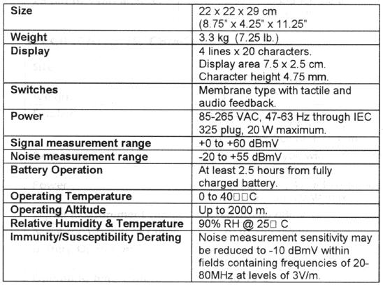
27 Page 26 OPTIONS: SPECIFICATIONS, CBM-1
28 Page 27 WARRANTY Relcom Inc. warrants the Monitor to perform as described in this manual under normal use for a period of ONE YEAR after delivery to the original purchaser. This warranty does not apply if the Monitor has been disassembled, modified or used for purposes other then those described in this manual. Upon verification of any defect, Relcom Inc. shall, at its option, repair or replace the defective unit. Before using the Monitor, the user should determine its suitability for the intended use. The user assumes all risk and liability whatsoever in connection with such use. In no event does Relcom Inc. assume liability for incidental or consequential damages. This warranty is the extent of the obligation or liability assumed by Relcom Inc. and no other warranty or guarantee is either expressed or implied. Relcom Inc. reserves the right to make design changes to the Monitor without notice and no obligation to make the same or similar changes to units previously manufactured. All statements in this manual are based on information believed to be reliable. Relcom Inc. is not, however, responsible for any errors or omissions. If you have any questions or suggestions, please contact: Relcom Inc. Forest Grove, OR USA Tel: or Fax: info@relcominc.com
Noise Detector ND-1 Operating Manual
 Noise Detector ND-1 Operating Manual SPECTRADYNAMICS, INC 1849 Cherry St. Unit 2 Louisville, CO 80027 Phone: (303) 665-1852 Fax: (303) 604-6088 Table of Contents ND-1 Description...... 3 Safety and Preparation
USER MANUAL FOR THE ANALOGIC GAUGE FIRMWARE VERSION 1.1
 by USER MANUAL FOR THE ANALOGIC GAUGE FIRMWARE VERSION 1.1 www.aeroforcetech.com Made in the USA! WARNING Vehicle operator should focus primary attention to the road while using the Interceptor. The information
Vorne Industries. 87/719 Analog Input Module User's Manual Industrial Drive Itasca, IL (630) Telefax (630)
 Telefax (630)") Vorne Industries 87/719 Analog Input Module User's Manual 1445 Industrial Drive Itasca, IL 60143-1849 (630) 875-3600 Telefax (630) 875-3609 . 3 Chapter 1 Introduction... 1.1 Accessing Wiring Connections
Vorne Industries 87/719 Analog Input Module User's Manual 1445 Industrial Drive Itasca, IL 60143-1849 (630) 875-3600 Telefax (630) 875-3609 . 3 Chapter 1 Introduction... 1.1 Accessing Wiring Connections
For warranty service, please contact Microframe at: A technician will gladly assist you.
 Your Microframe System is warranted against failure due to defects in workmanship or material for a period of one (1) year from the date of purchase. Microframe Corporation will repair or replace any defective
TRIPLETT. PairMaster. Lan Cable Test Set. Instruction Manual
 TRIPLETT PairMaster Lan Cable Test Set Instruction Manual The PairMaster LAN CABLE TEST SET INSTRUCTION MANUAL IMPORTANT SAFETY INSTRUCTIONS SAVE THESE INSTRUCTIONS Before using the PairMaster, read all
OTM FREQUENCY AGILE 750MHz F.C.C. COMPATIBLE TELEVISION MODULATOR INSTRUCTION MANUAL
 OTM-4000 FREQUENCY AGILE 750MHz F.C.C. COMPATIBLE TELEVISION MODULATOR INSTRUCTION MANUAL Phone: (209) 586-1022 (800) 545-1022 Fax: (209) 586-1026 E-Mail: salessupport@olsontech.com 025-000331 REV B www.olsontech.com
NS-3 RF Noise Source Operation Manual
 RF Noise Source Operation Manual Version 2.04 June 3, 2016 SPECIFICATIONS Frequency... Maximum output level... Output flatness... (at max output level) Impedance... Displayed level... Repeatability...
Quick Start. RSHS1000 Series Handheld Digital Oscilloscope
 Quick Start RSHS1000 Series Handheld Digital Oscilloscope General Safety Summary Carefully read the following safety precautions to avoid personal injury and prevent damage to the instrument or any products
SCALE & WEIGHT DISPLAYS
 The MICRO SERIES SCALE & WEIGHT DISPLAYS LARGE DIGIT MODELS Mighty-5S DPM MODELS Micro-S & Mighty-1S Mighty-1S Micro-S ELECTRO-NUMERICS, INC. Introduction The Electro-Numerics family of Digital Panel Meters
Kramer Electronics, Ltd. USER MANUAL. Models: VS-162AV, 16x16 Audio-Video Matrix Switcher VS-162AVRCA, 16x16 Audio-Video Matrix Switcher
 Kramer Electronics, Ltd. USER MANUAL Models: VS-162AV, 16x16 Audio-Video Matrix Switcher VS-162AVRCA, 16x16 Audio-Video Matrix Switcher Contents Contents 1 Introduction 1 2 Getting Started 1 3 Overview
USER MANUAL FOR THE ANALOGIC GAUGE FIRMWARE VERSION 1.0
 by USER MANUAL FOR THE ANALOGIC GAUGE FIRMWARE VERSION 1.0 www.aeroforcetech.com Made in the USA! WARNING Vehicle operator should focus primary attention to the road while using the Interceptor. The information
NT-9600 Wireless Barcode Scanner. Introduction
 Guangzhou Netum Electronic Technology Co., Ltd TEL: +86 20 82679969*816 FAX: +86 20 82684887 E-mail: scottchiu@gzxlscan.com Address: Unit137, the Pacific Industry Area, Xintang Town, Zengcheng District,
Model 6010 Four Channel 20-Bit Audio ADC Data Pack
 Model 6010 Four Channel 20-Bit Audio ADC Data Pack Revision 3.1 SW v1.0.0 This data pack provides detailed installation, configuration and operation information for the Model 6010 Four Channel 20-bit Audio
USER INSTRUCTIONS MODEL CSI-200 COAXIAL SYSTEM INTERFACE
 USER INSTRUCTIONS MODEL CSI-200 COAXIAL SYSTEM INTERFACE 9350-7676-000 Rev B, 5/2001 PROPRIETARY NOTICE The RTS product information and design disclosed herein were originated by and are the property of
3-DRX. AUTOMATIC THREE CHANNEL DIGITAL AES/EBU REPEATER and ANALOG AUDIO SWITCHER INSTALLATION AND OPERATING MANUAL
 3-DRX AUTOMATIC THREE CHANNEL DIGITAL AES/EBU REPEATER and ANALOG AUDIO SWITCHER INSTALLATION AND OPERATING MANUAL 3-DRX SECTION 1 INTRODUCTION The TITUS TECHNOLOGICAL LABORATORIES 3-DRX AUTOMATIC THREE
Introduction Display...1 Mounting...1 Firmware Version...2. ADL Operation... 3
 MoTeC MDD User Manual Contents Introduction... 1 Display...1 Mounting...1 Firmware Version...2 ADL Operation... 3 1. Full ADL Display...4 2. Gain Loss Layout for ADL...6 3. Large Numeric Layout for ADL...8
Telesto Private Wire Modem Manual
 Telesto Private Wire Modem Manual Telesto Private Wire Modem Manual Revision History Filenames are: G:\Company\Manuals &graphics\manuals \ReferenceManual\Components\Telesto_modem\Private Wire\Remote\RevA\CompleteManual\TelestoPwModemCover.lwp
Operating Instructions
 CNTX Contrast sensor Operating Instructions CAUTIONS AND WARNINGS SET-UP DISTANCE ADJUSTMENT: As a general rule, the sensor should be fixed at a 15 to 20 angle from directly perpendicular to the target
COMPOSITE VIDEO LUMINANCE METER MODEL VLM-40 LUMINANCE MODEL VLM-40 NTSC TECHNICAL INSTRUCTION MANUAL
 COMPOSITE VIDEO METER MODEL VLM- COMPOSITE VIDEO METER MODEL VLM- NTSC TECHNICAL INSTRUCTION MANUAL VLM- NTSC TECHNICAL INSTRUCTION MANUAL INTRODUCTION EASY-TO-USE VIDEO LEVEL METER... SIMULTANEOUS DISPLAY...
ROUGH DRAFT. Guide. Installation. Signal Booster. Wilson. AG Pro 75 Smart Technology In-Building Wireless 800/1900 Signal Booster.
 Signal Booster Installation Guide Contents: AG Pro 75 Smart Technology In-Building Wireless 800/1900 Signal Booster Before Getting Started.... 1 Antenna Options & Accessories.................... 1 Easy
RD RACK MOUNT DIMMER OWNERS MANUAL VERSION /09/2011
 RD - 122 RACK MOUNT DIMMER OWNERS MANUAL VERSION 1.3 03/09/2011 Page 2 of 14 TABLE OF CONTENTS UNIT DESCRIPTION AND FUNCTIONS 3 POWER REQUIREMENTS 3 INSTALLATION 3 PLACEMENT 3 POWER CONNECTIONS 3 OUTPUT
Dish Diversity Switch
 www.travel-vision.com Dish Diversity Switch INSTALLATION & USER S MANUAL Version 3.1 October 2013 PREFACE The information in this Installation and User s Manual is subject to change in order to improve
Peak Atlas IT. RJ45 Network Cable Analyser Model UTP05. Designed and manufactured with pride in the UK. User Guide
 GB05-7 Peak Atlas IT RJ45 Network Cable Analyser Model UTP05 Designed and manufactured with pride in the UK User Guide Peak Electronic Design Limited 2001/2013 In the interests of development, information
Model 5240 Digital to Analog Key Converter Data Pack
 Model 5240 Digital to Analog Key Converter Data Pack E NSEMBLE D E S I G N S Revision 2.1 SW v2.0 This data pack provides detailed installation, configuration and operation information for the 5240 Digital
Installation and Setting up Instructions for the 990 Signal Conditioning Instrument
 Installation and Setting up Instructions for the 990 Signal Conditioning Instrument Contents Page 1.0 Overview... 3 2.0 Installation.. 4 2.1 Electrical connections... 4 2.2 Cable selection... 4 2.3 Electrical
Model 5250 Five Channel Digital to Analog Video Converter Data Pack
 Model 5250 Five Channel Digital to Analog Video Converter Data Pack E NSEMBLE D E S I G N S Revision 3.1 SW v2.0.1 This data pack provides detailed installation, configuration and operation information
SNG-2150C User s Guide
 SNG-2150C User s Guide Avcom of Virginia SNG-2150C User s Guide 7730 Whitepine Road Revision 001 Richmond, VA 23237 USA GENERAL SAFETY If one or more components of your earth station are connected to 120
TC Mbps - 622Mbps FIBER OPTIC MODE CONVERTER/REPEATER (Rev A0.1) User's Manual
 User's Manual") TC3004 50Mbps - 622Mbps FIBER OPTIC MODE CONVERTER/REPEATER (Rev A0.1) MODEL: S/N: DATE: Notice! Although every effort has been made to insure that this manual is current and accurate as of date of publication,
TC3004 50Mbps - 622Mbps FIBER OPTIC MODE CONVERTER/REPEATER (Rev A0.1) MODEL: S/N: DATE: Notice! Although every effort has been made to insure that this manual is current and accurate as of date of publication,
MODEL OTM-4870 FREQUENCY AGILE 870MHz F.C.C. COMPATIBLE TELEVISION MODULATOR
 MODEL OTM-4870 FREQUENCY AGILE 870MHz F.C.C. COMPATIBLE TELEVISION MODULATOR USERS MANUAL Phone: (209) 586-1022 (800) 545-1022 Fax: (209) 586-1026 E-Mail: salessupport@olsontech.com 025-000412 Rev. B www.olsontech.com
Kramer Electronics, Ltd. USER MANUAL. Model: VS x 1 Sequential Video Audio Switcher
 Kramer Electronics, Ltd. USER MANUAL Model: VS-120 20 x 1 Sequential Video Audio Switcher Contents Contents 1 Introduction 1 2 Getting Started 1 2.1 Quick Start 2 3 Overview 3 4 Installing the VS-120 in
Model 5405 Dual Analog Sync Generator Data Pack
 Model 5405 Dual Analog Sync Generator Data Pack E NSEMBLE D E S I G N S Revision 2.1 SW v2.0 This data pack provides detailed installation, configuration and operation information for the 5405 Dual Analog
HD-CM HORIZON DIGITAL CABLE METER
 HD-CM OFF! Max RF i/p = +17dBm 75Ω Max AC/DC i/p = 120Vrms MENU INPUT ON HORIZON DIGITAL CABLE METER Horizon Global Electronics Ltd. Unit 3, West Side Flex Meadow Harlow, Essex CM19 5SR Phone: +44(0) 1279
ST-4000 SIGNAL LEVEL METER
 ST-4000 SIGNAL LEVEL METER Table of Contents Features / Specifications.... 1 Keypad Illustration....... 2 Keypad Controls.... 2 Getting Started: Powering the Meter.... 3 Quick Use Instructions.. 3 Main
EZCOM-1. PLC - to - AMS MESSAGE DISPLAY INTERFACE INSTALLATION AND OPERATING INSTRUCTIONS. Rev March, 2001
 EZCOM-1 PLC - to - AMS MESSAGE DISPLAY INTERFACE INSTALLATION AND OPERATING INSTRUCTIONS Rev 1.3 - March, 2001 CONTENTS Page INTRODUCTION 1 SPECIFICATIONS 1 LIST OF SUPPLIED ITEMS 1 INSTALLATION & TESTING
TECHNICAL SUPPORT , or FD151CV-LP Installation and Operation Manual 15.1 Low Profile LCD
 TECHNICAL SUPPORT 678-867-6717, or www.flightdisplay.com FD151CV-LP Installation and Operation Manual 15.1 Low Profile LCD FD151CV-LP 15.1" Low Profile LCD 2006 Flight Display Systems. All Rights Reserved.
OSD. EXECUTIVE / MiniDome USERS MANUAL. USING THE MOTOSAT DISH POINTING SYSTEM EXECUTIVE / MiniDome OSD
 EXECUTIVE / MiniDome OSD USERS MANUAL USING THE MOTOSAT DISH POINTING SYSTEM EXECUTIVE / MiniDome OSD MotoSAT Corporation Created April 22, 2003 1-800-247-7486 CONGRATULATIONS! on your purchase of your
FD104CV. Installation and Operation Manual 10.4 LCD MAN FD104CV. TECHNICAL SUPPORT , or Document Number: Rev:
 Page 1 of 16 FD104CV Installation and Operation Manual 10.4 LCD TCHNICAL SUPPORT 678-867-6717, or www.flightdisplay.com Page 2 of 16 FD104CV 10.4 LCD 2006 Flight Display Systems. All Rights Reserved. Flight
Safety Information. Camera System. If you back up while looking only at the monitor, you may cause damage or injury. Always back up slowly.
 Table of Contents Introduction...3 Safety Information...4-6 Before Beginning Installation...7 Installation Guide...8 Wiring Camera & Monitor...9-10 Replacement Installation Diagram...11 Clip-On Installation
TR-2 OPERATION MANUAL
 TR-2 OPERATION MANUAL Trilithic Company Profile Trilithic is a privately held manufacturer founded in 1986 as an engineering and assembly company that built and designed customer-directed products for
SPECIAL SPECIFICATION :1 Video (De) Mux with Data Channel
 Mux with Data Channel") 1993 Specifications CSJ 0924-06-223 SPECIAL SPECIFICATION 1160 8:1 Video (De) Mux with Data Channel 1. Description. This Item shall govern for furnishing and installing an 8 channel digital multiplexed
1993 Specifications CSJ 0924-06-223 SPECIAL SPECIFICATION 1160 8:1 Video (De) Mux with Data Channel 1. Description. This Item shall govern for furnishing and installing an 8 channel digital multiplexed
SR - 516D DESK TOP DMX REMOTE STATION. Version: Date: 05/16/2013
 SR - 516D DESK TOP DMX REMOTE STATION Version: 1.10 Date: 05/16/2013 Page 2 of 10 TABLE OF CONTENTS DESCRIPTION 3 POWER REQUIREMENTS 3 INSTALLATION 3 CONNECTIONS 3 POWER CONNECTIONS 3 DMX CONNECTIONS 3
C-net WIND. User s Guide
 C-net WIND User s Guide EMC Directive 89/336/EEC This product has been designed to be compliant with the above EMC Directive. Maximum performance and compliance with the EMC Directive can only be ensured
MS2540 Current Loop Receiver with RS485 Communication
 MS2540 Current Loop Receiver with RS485 Communication User Manual Metal Samples Company A Division of Alabama Specialty Products, Inc. 152 Metal Samples Rd., Munford, AL 36268 Phone: (256) 358 4202 Fax:
Integrator s Guide Avalon
 Integrator s Guide Avalon HD Component Video / Digital Audio Matrix Switch 2 Table of Contents Table of Contents... 2 Introduction... 3 Features:... 3 Installation... 4 Unpacking... 4 Front Panel Protective
INSTALLATION MANUAL FT-FOTR-1VDE-ST-S
 INSTALLATION MANUAL FT-FOTR-1VDE-ST-S 1-Channel Digital Duplex Baseband Video Transmitter and Receiver With Reverse Data Transmission & Ethernet Transmission v1.0 4/5/11 1 PACKAGE CONTENTS This package
Master Time Clock MTC Users Manual
 Master Time Clock MTC-6000 Users Manual Midwest Time Control Phone (972)987-4408 Toll Free (888)713-0373 FAX (877)720-9291 www.midwest-time.com sales@midwest-time.com TABLE OF CONTENTS TOPIC PAGE GENERAL
TRIPLETT HDMI2. High Definition Cable Tester. Instruction Manual
 TRIPLETT WireMaster HDMI2 High Definition Cable Tester Instruction Manual 84-893 10 / 2010 WireMaster HDMI FEATURES Lightweight, Rugged, Simple to use Test fragile, easily damaged HDMI Patch Cables and
Model PSKIT-H540 Ultrasonic Power Supply Kit 40 khz 500 Watts
 Model PSKIT-H540 Ultrasonic Power Supply Kit 40 khz 500 Watts INSTRUCTION MANUAL Sonics & Materials, Inc. 53 Church Hill Road Newtown, CT 06470 USA 203.270.4600 800.745.1105 203.270.4610 fax www.sonics.com
MATE3 Owner s Manual Addendum
 Purpose MATE3 Owner s Manual Addendum This document is an addendum to 900-0117-01-00, Revision C of the MATE3 System Display and Controller Owner s Manual. It provides descriptions of changes to the MATE3
innkeeper LTD Digital Hybrid User Guide JK Audio
 innkeeper LTD Digital Hybrid User Guide JK Audio Introduction Innkeeper LTD allows you to send line level signals into the phone line while maintaining excellent separation between your voice and the caller.
MENU EXECUTE Shiloh Road Alpharetta, Georgia (770) FAX (770) Toll Free
 FAX (770) Toll Free") Instruction Manual Model 2584-31 Combiner May 2011, Rev. A RF MONITOR GAIN = -15 MENU MODEL 2584 COMBINER CROSS TECHNOLOGIES INC. ALARM REMOTE POWER EXECUTE Data, drawings, and other material contained
Instruction Manual Model 2584-31 Combiner May 2011, Rev. A RF MONITOR GAIN = -15 MENU MODEL 2584 COMBINER CROSS TECHNOLOGIES INC. ALARM REMOTE POWER EXECUTE Data, drawings, and other material contained
PicoScope 3000 Series Automotive User guide
 PicoScope 3000 Series Automotive User guide PS3000A044 v1.0 I PicoScope 3000 Series Automotive PC Oscilloscopes Table of Contents 1 Introduction...2...2 1 Overview...2 2 Minimum PC requirements...2 3 Installation
Assembly Level Service Guide
 Assembly Level Service Guide This guide describes how to service the Agilent 53150A, 53151A, and 53152A Microwave Frequency Counters. The information in this guide applies to instruments having the number
Operating Instructions
 Operating Instructions HAEFELY TEST AG KIT Measurement Software Version 1.0 KIT / En Date Version Responsable Changes / Reasons February 2015 1.0 Initial version WARNING Introduction i Before operating
OWNERS MANUAL LUNATEC V3 MICROPHONE PREAMPLIFIER AND A/D CONVERTER
 OWNERS MANUAL LUNATEC V3 MICROPHONE PREAMPLIFIER AND A/D CONVERTER LUNATEC 35 +48 35 +48 30 40 30 40 0 25 45 25 45 3 192 1 1 6 176.4 20 50 20 50 9 96 12 PEAK 88.2 55 55 RESET 48 10 60 2 10 60 2 21 44.1
Operation/Reference Guide IRIS. Infrared/Serial Data Capture Unit. Control System Accessories
 Operation/Reference Guide IRIS Infrared/Serial Data Capture Unit Control System Accessories Last Revised: 1/17/2007 AMX Limited Warranty and Disclaimer All products returned to AMX require a Return Material
Multicom Optical Return Path Receiver MUL HRPR 4B
 Multicom Optical Return Path Receiver User Manual v.9 www.multicominc.com 800 423 2594 407 331 7779 1076 Florida Central Parkway, Longwood, FL 32750 SAFETY NOTIFICATION Multicom strongly advises you to
ST-4000D SIGNAL LEVEL METER
 ST-4000D SIGNAL LEVEL METER Rev 100606 Table of Contents Features / Specifications.... 1 Keypad Illustration....... 2 Keypad Controls.... 2 Getting Started: Powering the Meter...... 3 Quick Use Instructions.....
ARS x4 MATRIX SWITCHER Instruction Manual
 ARS-8400 8x4 MATRIX SWITCHER Instruction Manual Thank you for purchasing one of our products. Please read this manual before using this product. When using this product, always follow the instructions
AES-402 Automatic Digital Audio Switcher/DA/Digital to Analog Converter
 Broadcast Devices, Inc. AES-402 Automatic Digital Audio Switcher/DA/Digital to Analog Converter Technical Reference Manual Broadcast Devices, Inc. Tel. (914) 737-5032 Fax. (914) 736-6916 World Wide Web:
INSTRUCTION MANUAL FOR MODEL IOC534 LOW LATENCY FIBER OPTIC TRANSMIT / RECEIVE MODULE
 210 South Third Street North Wales, PA USA 19454 (T) 215-699-2060 (F) 215-699-2061 INSTRUCTION MANUAL FOR LOW LATENCY FIBER OPTIC TRANSMIT / RECEIVE MODULE i TO THE CUSTOMER Thank you for purchasing this
MONITOR POWER Shiloh Road Alpharetta, Georgia (770) FAX (770) Toll Free
 FAX (770) Toll Free") Instruction Manual Model 2099-10xx 10MHz Frequency Source April 2014, Rev. H MENU INTERNAL LEVEL = +10dBm MONITOR POWER 1 2 MODEL 2099 FREQUENCY SOURCE CROSS TECHNOLOGIES INC. ALARM OVEN REMOTE EXECUTE
Instruction Manual Model 2099-10xx 10MHz Frequency Source April 2014, Rev. H MENU INTERNAL LEVEL = +10dBm MONITOR POWER 1 2 MODEL 2099 FREQUENCY SOURCE CROSS TECHNOLOGIES INC. ALARM OVEN REMOTE EXECUTE
TRIPLETT WireMaster HDMI
 TRIPLETT WireMaster HDMI High Definition Cable Tester Instruction Manual 84-881 9/09 WireMaster HDMI FEATURES Lightweight, Rugged, Simple to use Test fragile, easily damaged HDMI Patch Cables and In-wall
USER MANUAL. DV-HSW-41 HDMI 4x1 SWITCHER LIT Bergen Boulevard, Woodland Park, NJ Tel FAX Web
 USER MANUAL DV-HSW-41 HDMI 4x1 SWITCHER 244 Bergen Boulevard, Woodland Park, NJ 07424 Tel 973-785-4347 FAX 973-785-3318 Web www.fsrinc.com LIT1372 PROPRIETARY INFORMATION All information in this manual
Part No. ENC-LAB01 Users Manual Introduction EncoderLAB
 PCA Incremental Encoder Laboratory For Testing and Simulating Incremental Encoder signals Part No. ENC-LAB01 Users Manual The Encoder Laboratory combines into the one housing and updates two separate encoder
VideoStamp 8 TM. Eight channel on-screen composite video character and graphic overlay with real-time clock. Version 1.01
 VideoStamp 8 TM Eight channel on-screen composite video character and graphic overlay with real-time clock Version 1.01 Copyright 2008 Intuitive Circuits, LLC D escription VideoStamp 8 is an eight channel
AES-404 Digital Audio Switcher/DA/Digital to Analog Converter
 Broadcast Devices, Inc. AES-404 Digital Audio Switcher/DA/Digital to Analog Converter Technical Reference Manual Broadcast Devices, Inc. Tel. (914) 737-5032 Fax. (914) 736-6916 World Wide Web: www.broadcast-devices.com
DP1 DYNAMIC PROCESSOR MODULE OPERATING INSTRUCTIONS
 DP1 DYNAMIC PROCESSOR MODULE OPERATING INSTRUCTIONS and trouble-shooting guide LECTROSONICS, INC. Rio Rancho, NM INTRODUCTION The DP1 Dynamic Processor Module provides complete dynamic control of signals
PicoScope 4000 Automotive PC Oscilloscopes
 PicoScope 4000 Automotive PC Oscilloscopes User's Manual ps4000a.en-1 Copyright 2008 Pico Technology Ltd. All rights reserved. Contents I Contents 1 Introduction...1 1 Overview...1...1 2 Minimum PC requirements...2
Element 78 MPE-200. by Summit Audio. Guide To Operations. for software version 1.23
 Element 78 MPE-200 by Summit Audio Guide To Operations for software version 1.23 TABLE OF CONTENTS IMPORTANT SAFETY AND GROUNDING INSTRUCTIONS COVER 1. UNPACKING AND CONNECTING...3 AUDIO CONNECTIONS...4
FOTS100 User Manual. BIOPAC Systems, Inc. Opsens Inc. 42 Aero Camino, Goleta, CA Tel (805) , Fax (805)
 , Fax (805)") FOTS100 User Manual BIOPAC Systems, Inc. 42 Aero Camino, Goleta, CA 93117 Tel (805) 685-0066, Fax (805) 685-0067 WWW.BIOPAC.COM 1 WARRANTY All products manufactured by Opsens inc. are warranted to be free
FOTS100 User Manual BIOPAC Systems, Inc. 42 Aero Camino, Goleta, CA 93117 Tel (805) 685-0066, Fax (805) 685-0067 WWW.BIOPAC.COM 1 WARRANTY All products manufactured by Opsens inc. are warranted to be free
BER MEASUREMENT IN THE NOISY CHANNEL
 BER MEASUREMENT IN THE NOISY CHANNEL PREPARATION... 2 overview... 2 the basic system... 3 a more detailed description... 4 theoretical predictions... 5 EXPERIMENT... 6 the ERROR COUNTING UTILITIES module...
384A Adapter Installation Instructions
 Instruction Sheet 860237684 Issue 9, October 2012 SYSTIMAX Solutions 384A Adapter Installation Instructions General The 384A adapter (Figure 1) is a broadband video adapter that provides connectivity to
Introduction to LasrPlay and DVDplay Synchronizers
 Introduction to LasrPlay and DVDplay Synchronizers Multi-channel Synchronizers and Controllers for Pioneer Laserdisc and DVD Video players Dave Jones Design Dave Jones Design 87 Chestnut St., Owego, NY
RX40_V1_0 Measurement Report F.Faccio
 RX40_V1_0 Measurement Report F.Faccio This document follows the previous report An 80Mbit/s Optical Receiver for the CMS digital optical link, dating back to January 2000 and concerning the first prototype
Getting started with
 Getting started with Electricity consumption monitoring single phase for homes and some smaller light commercial premises OVERVIEW: The OWL Intuition-e electricity monitoring system comprises of three
LAN Network Tester. Operating Manual. Part No TRIAX - your ultimate connection
 LAN Network Tester Part No. 157011 Operating Manual TRIAX - your ultimate connection Safety and Disposal The LAN Network Tester operates off 6V DC only. Only use the internal, battery powered, 6V power
Analog to Digital conversion of HD video. The HD-Now provides a simple method of upgrading ROVs for live HD. Keep existing infrastructure intact.
 Analog to Digital conversion of HD video The HD-Now provides a simple method of upgrading ROVs for live HD. Keep existing infrastructure intact. Most ROVs have at least one spare fiber. Utilizing a spare
FiberLink 7142 Series
 MANUAL FiberLink 7142 Series 4 Channels of Composite Video and 8 Channels of Audio over one single mode or multimode fiber Installation and Operations Manual WWW.ARTEL.COM FibeLink 7142 Series Contents
MP-204D Digital/Analog Stereo Monitor Panel
 MP-204D Digital/Analog Stereo Monitor Panel Videoquip Research Limited 595 Middlefield Road, Unit #4 Scarborough, Ontario, Canada. MIV 3S2 (416) 293-1042 1-888-293-1071 www.videoquip.com 1 Videoquip MP-204D
Model 7600 HD/SD Embedder/ Disembedder Data Pack
 Model 7600 HD/SD Embedder/ Disembedder Data Pack E NSEMBLE D E S I G N S Revision 2.1 SW v2.0.1 This data pack provides detailed installation, configuration and operation information for the 7600 HD/SD
Model Colorado Ultra Wide Bandwidth HDTV Matrix Switch
 HDTV Supply, Inc www.hdtvsupply.com Model Colorado Ultra Wide Bandwidth HDTV Matrix Switch Overview: This product is a full featured video & audio matrix switch. It is most commonly used to independently
instruction manual model 315 video sync separator s/n
 instruction manual model 315 video sync separator s/n colorado video, inc boulder, colorado january 2016 WARNING This equipment generates, uses and can radiate radio frequency energy and if not installed
FBT-6. Relcom. Fieldbus. fieldbus powered USB. FOUNDATION Fieldbus. segment. Recording the. segment. The Monitor collects this transfer to.
 Fieldbus Diagnostic Monitor Relcom FBT-6 fieldbus powered device add & drop indication shield short indication measures low, fieldbus and high frequency average and peak noise measures signal level for
INSTALLATION INSTRUCTIONS MODEL VSBX-236 LED 3 X 8 INDOOR SCOREBOARD
 1 INSTALLATION INSTRUCTIONS MODEL VSBX-236 LED 3 X 8 INDOOR SCOREBOARD NOTE TO INSTALLERS: PLEASE RETURN THIS MANUAL TO THE INDIVIDUAL IN CHARGE OF THE SCOREBOARD UPON COMPLETION OF INSTALLATION. The scoreboard
Kramer Electronics, Ltd. USER MANUAL. Model: VP-4x4. 4x4 VGA/XGA Audio Matrix Switcher
 Kramer Electronics, Ltd. USER MANUAL Model: VP-4x4 4x4 VGA/XGA Audio Matrix Switcher Contents Contents 1 Introduction 1 2 Getting Started 1 3 Overview 2 4 Your VGA/XGA Audio Matrix Switcher 2 4.1 Connecting
DSA-1. The Prism Sound DSA-1 is a hand-held AES/EBU Signal Analyzer and Generator.
 DSA-1 The Prism Sound DSA-1 is a hand-held AES/EBU Signal Analyzer and Generator. The DSA-1 is an invaluable trouble-shooting tool for digital audio equipment and installations. It is unique as a handportable,
DTV742 Installation Quick Start Guide
 DTV742 Installation Quick Start Guide The Wegener Model DTV742 8VSB 4-Channel Multiplexor receives VHF/UHF broadcast HDTV signals and provides output ASI streams for connection to cable system QAM modulators.
Manual of Operation for WaveNode Model WN-2m. Revision 1.0
 Manual of Operation for WaveNode Model WN-2m. Revision 1.0 TABLE OF CONTENTS 1. Description of Operation 2. Features 3. Installation and Checkout 4. Graphical Menus 5. Information for Software Expansion
Model 1476-C SuperQuad HR
 Model 1476-C SuperQuad HR Installation and Operating Instructions Table of Contents Page Table of Content... 2 System Description... 3 Features... 3 Installation... 4 Internal Setups... 4 Connections...
OPTICAL POWER METER WITH SMART DETECTOR HEAD
 OPTICAL POWER METER WITH SMART DETECTOR HEAD Features Fast response (over 1000 readouts/s) Wavelengths: 440 to 900 nm for visible (VIS) and 800 to 1700 nm for infrared (IR) NIST traceable Built-in attenuator
LavryBlack Series Model AD10 Analog to Digital Converter
 LavryBlack Series Model AD10 Analog to Digital Converter Lavry Engineering, Inc. P.O. Box 4602 Rolling Bay, WA 98061 http://lavryengineering.com email: techsupport@lavryengineering.com Rev 1.20 January
What to look for when choosing an oscilloscope
 What to look for when choosing an oscilloscope Alan Tong (Pico Technology Ltd.) Introduction For many engineers, choosing a new oscilloscope can be daunting there are hundreds of different models to choose
Commander 384. w w w. p r o l i g h t. c o. u k U S E R M A N U A L
 Commander 384 w w w. p r o l i g h t. c o. u k U S E R M A N U A L 1, Before you begin 1.1: Safety warnings...2 3 1.2: What is included...4 1.3: Unpacking instructions...4 2, Introduction 2.1: Features...4
Contents: 1 LANsmart Pro Main Unit 4 Remote Unit: ID1, ID2, ID3, ID4
 LANsmart Pro user manual Introduction LANsmart Pro is a hand-held, multifunction Cable Map Tester and Cable Length Meter. It has an integrated Analog and Digital Tone Generator, Port Finder, and Quick
GAUGEMASTER PRODIGY EXPRESS
 GAUGEMASTER PRODIGY EXPRESS DCC01 USER MANUAL Version 1.2 2014 1 T A B L E O F C O N T E N T S 1 Getting Started Introduction Specifications and Features Quick Start Connecting to Your Layout Running a
Start Up or Shut Down Hunting Function. Using the Receiver. If there is a short circuit in the cable, it will display as follows:
 If there is a short circuit in the cable, it will display as follows: Push key (No) to exit calibration function. Push key (Yes) to repeat measurement process. 11 Note: The calibration will recover the
User s Manual. Digital Switch Part #: DL-HDS21 Part #: DL-HDS41
 User s Manual Digital Switch Part #: DL-HDS21 Part #: DL-HDS41 TABLE OF CONTENTS 1-1 Table of Contents 1-2 Welcome and Safety Notes 1-3 Product Description and General Specifications 1-4 Environmental
Optical Receiver Manual. Transmitter OP-OR212JSE. Shenzhen Optostar Optoelectronics Co., Ltd (Version 2)
") Optical Receiver Manual Transmitter OP-OR212JSE Shenzhen Optostar Optoelectronics Co., Ltd 2016. 7(Version 2) 1. Summary OP-OR212JSE optical receiver is the latest 1GHz dual-way switch optical receiver.
Optical Receiver Manual Transmitter OP-OR212JSE Shenzhen Optostar Optoelectronics Co., Ltd 2016. 7(Version 2) 1. Summary OP-OR212JSE optical receiver is the latest 1GHz dual-way switch optical receiver.
Getting started with
 PART NO. CMA11 3 MADE IN CHINA 1. Measuring CAT II 2. Max. voltage 250V ~ 3. Max. current 71 Amp Getting started with Electricity consumption & Solar PV generation monitoring single phase, for homes fitted